JP4400810B2 - Image formation management device - Google Patents
Image formation management device Download PDFInfo
- Publication number
- JP4400810B2 JP4400810B2 JP2001244665A JP2001244665A JP4400810B2 JP 4400810 B2 JP4400810 B2 JP 4400810B2 JP 2001244665 A JP2001244665 A JP 2001244665A JP 2001244665 A JP2001244665 A JP 2001244665A JP 4400810 B2 JP4400810 B2 JP 4400810B2
- Authority
- JP
- Japan
- Prior art keywords
- information
- image forming
- virtual
- terminal
- network
- Prior art date
- Legal status (The legal status is an assumption and is not a legal conclusion. Google has not performed a legal analysis and makes no representation as to the accuracy of the status listed.)
- Expired - Fee Related
Links
Images


Description
【0001】
【発明の属する技術分野】
本発明は、ネットワークを介して接続されている複数のレーザプリンタ、印刷装置などの画像形成装置を管理する画像形成管理装置に関する。
【0002】
【従来の技術】
近年、ネットワーク環境の普及に伴い、複数の端末装置とプリンタ装置、ファクシミリ装置、レーザプリンタ、複写機、複合機などの画像形成装置がネットワーク接続により利用できるようになってきている。ユーザは自分の端末装置からネットワーク上の画像形成装置に対して、画像形成に関する用紙、印字濃度、印刷部数などの様々な設定を行い、印刷指定することができる。また、ネットワーク上の指定した画像形成装置が使用できないときには、別の画像形成装置による印刷指定を行うことも可能である。
このようなネットワークを介した印刷に関して、特開2000−222147号公報には、印刷処理を行うプリンタに対応して情報参照手段んを設けることにより、大がかりなプリントサーバを設ける必要がなく、プリントサーバに対するメンテナンスを簡素化することができるネットワークを介した印刷管理方法が記載されている。
【0003】
【発明が解決しようとする課題】
しかしながら、指定した画像形成装置において印刷をすることができないなどの理由から、ネットワーク上の他の画像形成装置を指定する場合、他の画像形成装置が備えている用紙の種類、印刷形式などを正確に把握していなければ、指定した印刷設定が実行可能な画像形成装置を再度選択することができない。また、印刷実行する画像形成装置が変更となる度に、印刷設定を仕直したりする必要が生じてしまう。さらには、再度選択した画像形成装置での印刷結果が希望した印刷結果とは異なる場合もある。このような様々な点から、ネットワーク上に接続されている複数の画像形成装置に関するメンテナンス情報、マニュアル、印刷形式、搭載している用紙サイズなどの画像形成装置情報の正確な管理が望まれてきている。
【0004】
そこで、本発明の第1の目的は、PC端末に接続されているネットワーク上の実在する画像形成装置を仮想的な画像形成装置として表示することができ、この仮想的な画像形成装置においてメンテナンスの指示やマニュアル操作を行うことができる画像形成管理装置を提供することである。
本発明の第2の目的は、PC端末上の仮想的な画像形成装置において、ユーザが使用したい機能を容易に探すことができる画像形成管理装置を提供することである。
本発明の第3の目的は、PC端末上の仮想的な画像形成装置において、即、ネットワーク上に実在する画像形成装置へのリモート操作を行うことができ、すべてPC端末上で操作することができる画像形成装置を提供することである。
【0005】
本発明の第4の目的は、ネットワーク上で管理する画像形成装置をカテゴリ別にデータベース化することにより、PC端末からの要求に応じて画像形成装置に関するページまたはデータを配信することができ、ページ配信側とページ取得側とが意識しない関係を成立することができる画像形成管理装置を提供することである。
本発明の第5の目的は、排紙先をネットワーク上のPC端末に表示される仮想的な画像形成装置と指定することで、アクセス可能なモバイル端末にも印刷結果を一種の掲示板のように提示することができる画像形成管理装置を提供することである。
本発明の第6の目的は、配信されたページに再度、仮想排紙(ネットワーク上のPC端末に表示される仮想的な画像形成装置を排紙先として指定)することで、印刷結果の確認とページ配信元へのレスポンスと両方を同時に実行することができ、この仮想排紙の対象となった当該ページを実際に用紙に通常印刷することができる画像形成管理装置を提供することである。
【0006】
【課題を解決するための手段】
請求項1の発明は、ネットワークを介して接続されている単数または複数の画像形成装置の管理を行い該画像形成装置の状態情報を情報処理装置に提供可能な画像形成管理装置であって、前記情報処理装置からアクセスに基づき画像形成管理装置の電源を投入する電源投入手段と、前記情報処理装置から前記画像形成装置の仮想装置情報の送信要求を受け付ける送信要求受付手段と、前記送信要求受付手段によって受け付けた仮想装置情報の送信要求に基づいて仮想装置画面を前記情報処理装置に提供する仮想装置画面提供手段と、複数の前記画像形成装置のメンテナンス、マニュアルなどの情報を装置情報として格納する装置情報格納手段と、前記装置情報格納手段内の複数の装置情報を地域、会社、業種などのカテゴリに分類し、カテゴリ別装置情報として格納する分類情報格納手段と、格納されたカテゴリ別装置情報の取得要求に基づき、カテゴリ別装置情報を前記情報処理装置に配信する仮想装置情報配信手段と、前記情報処理装置で選択されたカテゴリ内の装置情報を前記仮想装置画面上で表示させる装置情報表示手段と、を有することを特徴とする画像形成管理装置である。
【0011】
【発明の実施の形態】
以下、本発明の好適な実施の形態について図1ないし図12を参照して詳細に説明する。
図1は、第1の実施形態の画像形成管理システムの概念を示した図である。
図1に示されるように、画像形成管理システムは、本発明の一実施形態としてのWeb管理サーバー100を備え、このWeb管理サーバー100にネットワーク200を介して、Web管理サーバー100に対してユーザが所定の処理要求を送信する要求送信装置として機能するPC端末300と、このPC端末300からの処理要求に基づいてWeb管理サーバー100から送信される各処理要求に応じた処理を行う画像形成装置400とが接続されている。
なお、ネットワーク200は、一例としてインターネットとして説明するが、これに限られるものではなく、キャプテンシステム、その他のWAN(広域ネットワーク)など、PC端末300によってユーザがWeb管理サーバー100へ所定の処理要求を送信することができ、かつ、Web管理サーバー100がPC端末300から要求される所定の処理を実行することができるようなネットワークであればよい。また、ネットワーク200は、Web管理サーバー100とPC端末300、画像形成装置400とが、有線、無線および両方のいずれにより接続されるネットワークでもよく、専用線を介した回線による通信ネットワーク、携帯端末による無線通信ネットワーク、通信衛星等を使った情報通信ネットワークのいずれでもよい。
【0012】
図2は、本実施の形態に係る画像形成装置の概略構成を示したブロック図である。なお、本実施の形態では、画像形成装置400の一例としてレーザプリンタ(以下、LPという)に関して説明するが、これに限られるものではない。また、LPは、白黒、カラーのどちらでもよいものとする。
コントローラ1は、メインパワー16と接続しており、その時設定されている制御モードおよびホストマシン3からの制御コードに従ってホストマシン3からの印字データをビデオデータに変換してプリンタエンジン15へ出力する制御機構の総称であり、以下のようなモジュールで構成される。
ホストI/F(インターフェース)5は、外部から当該LPへの制御信号およびデータとLPからのステータス信号を送受信するインターフェースである。CPU(中央処理装置)9は、プログラムROM(リード・オンリ・メモリ)6のプログラム内容に従ってデータ処理をする。
RAM(ランダム・アクセス・メモリ)10は、CPU9のワーク領域、ホストマシン3からのデータ受信バッファ、また処理後のイメージ展開領域に使用される。
【0013】
NV−RAM11は、電源のON/OFF(オン/オフ)に関わらずデータを保持できる不揮発生メモリである。フォントROM7は、印字の時に使用される数種の書体を保持しているメモリである。
エンジンI/F12は、コントローラ1とプリンタエンジン15への制御信号とプリンタエンジン15からコントローラ1へのステータス信号を送受信するインターフェースである。
プリンタエンジン15は、コントローラ1からのビデオ信号と制御情報に基づいて感光体上に静電作像し、給紙部より転写紙を給紙して画像を形成する。
操作パネル4は、LPのステータス表示およびモード、印刷条件を変更できるスイッチ部である。
ディスクI/F14は、HDD(ハードディスクドライブ)17と接続しており、HDD17へのデータ送受信を行うインターフェースである。
ネットワークI/F13は、ディスクI/F14と接続しており、ネットワークを介して接続されている他のPC端末300、Web管理サーバー100、画像形成装置とデータを送受信するインターフェースである。
以上のモジュールを介してホストマシン3からの印字データを制御情報に基づいてページが完成するとプリンタエンジン15にプリンタスタート命令がかかり印刷が開始される。
【0014】
図3は、Web管理サーバーの構成を示した図である。以下、説明の都合上、画像形成装置400をLP400として説明する。また、LP400には、PC端末300の画面に表示される仮想LPと、ネットワーク200を介して接続されており、実際の印刷を実行する実LP(LP400に相当)とがあるものとして説明する。
Web管理サーバー100は、制御部110を備えており、データバス114などのバスラインを介して入出力部112、通信制御部113、記憶部115、図示しないその他の機器が互いに接続されているものとする。
制御部110は、プログラムに従って各種装置、各部を制御し演算するCPU(中央処理装置)、CPUが各種制御や演算を行うためのプログラムやデータを格納するROM(リード・オンリ・メモリ)、CPUにワーキングメモリとして使用されるRAM(ランダム・アクセス・メモリ)などを備えている。
以下、本実施の形態では一例として、ネットワーク200上の1つのPC端末300上に表示される仮想LPについて説明するが、これに限られるものではなく、複数のPC端末を設置することが可能であり、制御部110は、複数の各PC端末からの処理要求に同時に個別に対応できるようになっている。
【0015】
入出力部112は、ネットワーク200を介して接続されているPC端末300上のプリンタソフトウェアによる印刷設定、印刷要求などに対する所定の処理要求や各データを記憶部115に対して入出力する。通信制御部113は、一般電話回線、ISDN(統合ディジタル通信網)回線、無線電話回線(携帯電話、PHSなど)によりネットワーク100へ接続し、通信制御部113を制御する制御部110とともに、処理要求に対する応答機能の役割を果たしている。
記憶部115は、大容量の記憶装置であるハードディスクが主として使用されており、制御部110のCPUが各種制御や演算を行うためのプログラムやデータを格納し、本実施の形態の画像形成管理システムのプログラムとして機能するプログラム部116と、PC端末300からの印刷設定情報、印刷要求情報などの所定のデータを格納するデータベース117とを備えている。
記憶部115のプログラム部116には、データベース117に格納されるPC端末300上に表示される仮想LPに関する仮想排紙トレイ情報などのデータテーブルを更新するためのデータ更新プログラム、PC端末300からネットワーク200を介して所定の処理(例えば、仮想LPでのメンテナンス指示や方法の入手を希望するメンテナンス情報送信などのデータ送信処理)についてユーザによる処理要求を受信する要求受信処理プログラム、この要求受信処理プログラムにより受信された処理要求において要求されている処理(データ送信処理)を実行する要求処理実行プログラム、要求処理実行プログラムによって送信された各データに応じてPC端末300での仮想LPに関する情報を格納する格納プログラムが格納されている。
【0016】
また、プログラム部116には、PC端末300上に表示される仮想LPの仮想排紙トレイ情報を取得して管理者(ネットワークに接続されているLPを管理している業者)に提示するプログラム(ウェブ閲覧ソフトウェアなどにより実行されるプログラム)、管理者による当該仮想LPに関する仮想排紙トレイ情報の変更内容をPC端末300に通知する通知プログラム、LP所有者(PC端末300におけるユーザに相当することもある)とページ配信を利用したいユーザの登録を受け付けるプログラム、ネットワーク200上の接続を管理している複数LPをカテゴリ別にデータベース化し、ページ配信サービスのコンテンツとして掲載するプログラム、ページ配信サービスに対するユーザからの送信するページとカテゴリの指定を受け付けるプログラム、指定されたカテゴリに関するページを送信し、PC端末300上の仮想LPの仮想排紙トレイに表示するプログラム、仮想LPの仮想排紙トレイに印刷結果を表示し、当該印刷結果をコンテンツとして提供するプログラム、配信されたページに対するユーザからのレスポンス(応答)として、排紙先を仮想LPの仮想排紙トレイを選択して印刷すると返信された場合、当該返信データを対外HP(ホームページ)に掲載するプログラム、その他各種のプログラムが格納されている。
【0017】
データベース117には、ネットワーク200上の複数LPに関する情報、PC端末300に表示する仮想LPの情報および仮想排紙トレイ情報、カテゴリ別に分けたネットワーク200上の管理しているLP情報、コンテンツ情報、LP所有者とページ配信を利用したいユーザの登録情報、その他の各情報が格納されている。
【0018】
次に、第1の実施の形態の動作について説明する。
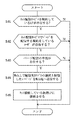
図4は、ネットワーク接続されているLPのメンテナンス、マニュアルを取得する処理手順を示したフローチャートである。
まず、PC端末300において、LP所有者であるユーザまたはネットワーク200のLP400で印刷を実行したいユーザが当該PC端末300からWeb管理サーバー100にアクセスすると、Web管理サーバー100の電源が投入される(ステップ41)。そして、希望の仮想LPに関する情報の送信要求をWeb管理サーバー100に送信すると、Web管理サーバー100の制御部110によってPC端末300の表示画面のWeb上に仮想LPが表示される(ステップ42;Y)。ここで、ユーザは、実LPの情報として表示される仮想LPの情報を参照することにより、実LPの状態を認識することができる。
【0019】
実LPで故障が発生していた場合(ステップ43;Y)、ユーザがPC端末300からWebブラウザを利用することにより、制御部110はLPメンテナンス情報が格納されているデータベース17に自動的にリンクして、想定原因をPC端末300に表示する(ステップ44)。また、制御部110は、仮想LP、すなわちLP400に関するマニュアルも自動的に表示する(ステップ45)。
そして、ユーザがWeb管理サーバー100へのアクセスを終了すると、Web管理サーバー100の電源は切断され(ステップ46;Y)、メンテナンスやマニュアルに関する情報取得処理が終了する。
【0020】
次に、第1の実施の形態の変形例(1)の動作について説明する。
図5は、ネットワーク接続されているLPの消耗品、部品などの注文処理手順を示したフローチャートである。
まず、PC端末300において、LP所有者であるユーザまたはネットワーク200のLP400で印刷を実行したいユーザが当該PC端末300からWeb管理サーバー100にアクセスすると、Web管理サーバー100の電源が投入される(ステップ51)。そして、希望の仮想LPに関する情報の送信要求をWeb管理サーバー100に送信すると、Web管理サーバー100の制御部110によってPC端末300の表示画面のWeb上に仮想LPが表示される(ステップ52;Y)。ここで、ユーザは、実LPの情報として表示される仮想LPの情報を参照することにより、実LPの状態を認識することができる。
【0021】
実LPの用紙、トナーなどの消耗品が不足しており、注文したい場合(ステップ53;Y)、すなわちユーザがPC端末300からWebブラウザを利用することにより、制御部110に消耗品注文要求をWeb管理サーバー100に送信すると、制御部110によってPC端末300にオーダーリストが表示される(ステップ54)。ここで、ユーザがオーダー(消耗品注文)をすると、このオーダー情報が制御部110によって該当するLP400の情報としてデータベース117に自動的に格納される(ステップ55)。
そして、ユーザがWeb管理サーバー100へのアクセスを終了すると、Web管理サーバー100の電源は切断され(ステップ56;Y)、消耗品注文に関する情報取得処理が終了する。
【0022】
次に、第1の実施の形態の変形例(2)の動作について説明する。
図6は、ネットワーク接続されているLPに関するソフトウェアやアプリケーションの注文処理手順を示したフローチャートである。
まず、PC端末300において、LP所有者であるユーザまたはネットワーク200のLP400で印刷を実行したいユーザが当該PC端末300からWeb管理サーバー100にアクセスすると、Web管理サーバー100の電源が投入される(ステップ61)。そして、希望の仮想LPに関する情報の送信要求をWeb管理サーバー100に送信すると、Web管理サーバー100の制御部110によってPC端末300の表示画面のWeb上に仮想LPが表示される(ステップ62;Y)。ここで、ユーザは、実LPの情報として表示される仮想LPの情報を参照することにより、実LPの状態を認識することができる。
【0023】
実LPに関するソフトウェア、アプリケーションなどを注文したい場合(ステップ63;Y)、すなわちユーザがPC端末300からWebブラウザを利用することにより、制御部110にソフトウェアやアプリケーションの注文要求をWeb管理サーバー100に送信すると、制御部110によってPC端末300にオーダーリストが表示される(ステップ64)。ここで、ユーザが製品に適合するオーダー(ソフトウェアまたはアプリケーションの注文)をすると、このオーダー情報が制御部110によって該当するLP400の情報としてデータベース117に自動的に格納される(ステップ65)。
そして、ユーザがWeb管理サーバー100へのアクセスを終了すると、Web管理サーバー100の電源は切断され(ステップ66;Y)、ソフトウェアやアプリケーションに関する情報取得処理が終了する。
【0024】
以上のように、第1の実施形態の画像形成管理システムでは、ネットワーク200上のPC端末300に仮想LPに関する情報を表示することにより、ユーザは、実LPの状態を認識することができ、また、実LPのリモートコントロールも実行することができる。
また、本実施の形態の画像形成管理システムでは、LP400がネットワーク接続されているので扱いにくい本体操作やマニュアル説明をPC端末300上の仮想LPにおいてグラフィカルに誘導することができるので、ユーザ自身で容易にメンテナンスを行うことができる。
また、本実施の形態の画像形成管理システムでは、PC端末300上の仮想LPの画面状態で部品や消耗品等のオーダーに関しても、その機種に適合する製品を案内することが可能であり、ユーザが容易にオーダーすることができる。
さらに、本実施の形態の画像形成管理システムでは、LP400に搭載するソフトウエアに必要なバージョンアップや新規ダウンロードについても仮想LPを通して行うことができる。
【0025】
次に、第2の実施形態について説明する。
図7は、第2の実施形態に係る画像形成管理システムの概念を示した図である。なお、説明上、第1の実施形態と同様の部分には同じ番号を付して、説明を省略する。
図7に示されるように、第2の実施形態の画像形成管理システムは、本発明の一実施形態としてのWeb管理サーバー100を備え、このWeb管理サーバー100にネットワーク200を介して、複数のPC端末300、300a、300b、300cと、LP(画像形成装置)400、400a、400b、400cとが接続されている。
第2の実施形態の画像形成管理システムでは、ネットワーク200上のLP情報をカテゴリ別にデータベース化し、ユーザやLP所有者からの要求に応じて、データベース化した情報を配信する(以下、ネット配信サービスという)実施形態である。なお、配信する情報としては、ネットワーク200上の他のLPで印刷されたページ情報、LP設定情報などがあげられる。なお、カテゴリとは地域、業種、会社の規模などをいうものとする。
【0026】
Web管理サーバー100の制御部110は、Web上にWWW対外HP(ホームページ)50を掲載し、ネットワーク200を介して接続されているLP400、400a、400b、400cの各LP所有者からのネット配信サービスの契約申請を受け付ける。Web管理サーバー100へのネット配信サービスに関する契約申請を受信した制御部110は、受信した各LP400、400a、400b、400cの情報をデータベース117にカテゴリ別やLP所有者ごとなどに分類し、格納する。
また、Web管理サーバー100の制御部110は、Web上に掲載したWWW対外HP(ホームページ)50において、LP所有者またはLP所有者以外でLP情報を取得したいユーザから、Web管理サーバー100に格納されている情報の取得要求があった場合、当該ユーザのPC端末上に情報を配信する。例えば、PC端末300aにおいてユーザがWWW対外HP50の「カテゴリ選択ここ」をクリックすると、PC端末300aにカテゴリ別に分類されたLP情報やLPにおいて実際に印刷されたページ情報などが表示される。ユーザがこの表示された情報画面において、希望するカテゴリやページ情報を指定すると、制御部110は、該当するカテゴリ内のLPのページ情報をPC端末300aの仮想LP上で印刷させ、仮想排紙トレイに排紙した状態を表示する。
なお、LP所有者とWeb管理サーバー100からページ情報の配信を受けたいユーザは、あらかじめにネット配信サービスに登録を行い、この登録したLP所有者やユーザがWeb管理サーバー100によるページ情報の配信にアクセスすることができるものとする。
【0027】
ここで、図8を参照して第2の実施形態の画像形成管理システムの動作について説明する。図8は、画像形成管理システムにおけるページ配信の処理手順を示したフローチャートである。
Web管理サーバー100の制御部110は、ネット配信サービスを契約しているLPがデータベース117内に存在する場合(ステップ81;Y)、Web上に掲載しているWWW対外HP50上に契約しているLPがある旨を表示する。ここで、Web管理サーバー100の制御部110は、ネット配信サービスでページを配信する契約をしているユーザが存在し(ステップ82;Y)、このユーザからWeb上に掲載しているWWW対外HP50にアクセスがあり、ページ配信の申請がされているかどうか確認する(ステップ83)。
ページ配信の申請がある場合(ステップ83;Y)、Web管理サーバー100の制御部110は、申請したユーザのPC端末へ配信を希望するカテゴリを表示し、カテゴリの選択を促し、ユーザによって選択されたカテゴリ内のページ情報をWeb上の指定された宛先に送信する(ステップ84)。そして、ネット配信サービスに登録しているユーザのPC端末上の仮想LP上で印刷させ、仮想排紙トレイに排紙した状態を表示する(ステップ85)。
【0028】
以上のように、第2の実施形態の画像形成管理システムでは、接続されてるLPをカテゴリ別にデータベース化するので、例えば、広告や発券(デリバリー的なフード関係のサービス券、トラベルサービス、エンターテイメントの発券のように不特定に配布するものをいう)などを目的の範囲内で仮想LPへの配信サービスによって配信することができ、ページ配信側とページ取得側とがお互いを意識しない関係を成立することができ、配信サービスを効果的に行うことができる。
【0029】
次に、第3の実施形態について説明する。
図9は、第3の実施形態に係る画像形成管理システムの概念を示した図である。なお、説明上、第1および第2の実施形態と同様の部分には同じ番号を付して、説明を省略する。
図9に示されるように、第3の実施形態の画像形成管理システムは、本発明の一実施形態としてのWeb管理サーバー100を備え、このWeb管理サーバー100にネットワーク200を介して、PC端末300およびLP(画像形成装置)400が接続されている。
第3の実施形態の画像形成管理システムでは、第2の実施形態でのネット配信サービスによって配信され、PC端末300上の仮想LP上で表示された仮想排紙トレイを指定すると、専用のWebページにLPで実際に印刷した場合の印刷結果が表示される実施形態である。
Web管理サーバー100では、第2の実施形態でネット配信サービスによるページ情報の配信を申請したPC端末300の仮想LPに表示された仮想排紙トレイをコンテンツとしてデータベース117に格納する。制御部110は、PC端末300から、または他のPC端末からこの仮想排紙トレイが指定されると、実LPで印刷された場合の印刷結果をWeb上の専用ページとしたこの仮想排紙トレイに表示する。
また、ユーザが指定した仮想排紙トレイのページ情報を実LPで印刷すると指定すると、制御部110は、ネットワーク200上のLP400に対して実際の用紙に印刷する印刷実行命令を送信する。
【0030】
ここで、図10を参照して第3の実施形態の画像形成管理システムの動作について説明する。図10は、画像形成管理システムにおける印刷結果表示の処理手順を示したフローチャートである。
まず、PC端末300において、LP所有者であるユーザまたはネットワーク200のLP400で印刷を実行したいユーザが当該PC端末300からWeb管理サーバー100にアクセスすると、Web管理サーバー100の電源が投入される(ステップ101)。ユーザがネット配信サービスを実行するWeb管理サーバー100の制御部110から配信されたページ情報の印刷を希望する場合(ステップ102;Y)、当該ユーザのPC端末300上の仮想LPに印刷を希望するページ情報が表示されているかどうかを確認する(ステップ103)。
仮想LP上にページ情報が表示されている場合(ステップ103;Y)、制御部110は、PC端末300上に当該ページ情報の排紙先としてWeb上の専用ページ(仮想排紙トレイ)を指定するかどうかの選択を促す表示を行う(ステップ104)。
【0031】
当該ページ情報の排紙先としてWeb上の専用ページが選択された場合(ステップ104;Y)、制御部110は、仮想LPに実LPで印刷された場合の印刷結果を排紙(表示)し、当該印刷結果をWeb上の専用ページに掲載するコンテンツとしてデータベース117に格納する(ステップ106)。これにより、他のユーザやLP所有者は、Web上の専用ページにモバイル端末やPDA(Personal Digital Assistants)によってアクセスすることにより、ページ情報の印刷結果を見たり確認したりして、掲示板のようにして利用することができる。
一方、排紙先としてWeb上の専用ページが選択されなかった場合(ステップ104;N)、制御部110は、このページ情報をネットワーク200上のLP400に対して用紙に印刷する印刷実行命令を送信する。そして、この印刷命令を受信したLP400によって用紙に印刷が実行される(ステップ105)。
そして、ユーザがWeb管理サーバー100へのアクセスを終了すると、Web管理サーバー100の電源は切断され(ステップ107;Y)、印刷結果表示先の指定処理が終了する。
以上のように、第3の実施形態の画像形成管理システムでは、ユーザ自身のデータも仮想LPの仮想排紙トレイに排紙する(Web上の専用ページとして掲載する)と指定できるので、モバイル端末やPDAからのアクセスで印刷結果を見たり確認したり掲示板のように扱うことができる。
【0032】
図11は、第4の実施形態に係る画像形成管理システムの概念を示した図である。なお、説明上、第1、第2および第3の実施形態と同様の部分には同じ番号を付して、説明を省略する。
図11に示されるように、第4の実施形態の画像形成管理システムは、本発明の一実施形態としてのWeb管理サーバー100を備え、このWeb管理サーバー100にネットワーク200を介して、PC端末300およびLP(画像形成装置)400が接続されている。
第4の実施形態の画像形成管理システムでは、第2の実施形態でのネット配信サービスによって配信され、PC端末300上の仮想LP上で表示された仮想排紙トレイ上のページ情報に対して、ユーザがWeb上の専用ページにLP400で実際に印刷した場合の印刷結果を表示すると指定した場合、この指定された排紙先の内容が返信となってWeb管理サーバー200に返信される実施形態である。
Web管理サーバー100の制御部110は、この返信されてきたページ情報をWWW対外HP501に返信内容として掲載し、当該返信されてきたページ情報(返信データ)をカテゴリ別やユーザ別に分類してデータベース117に格納する。
【0033】
ここで、図12を参照して第4の実施形態の画像形成管理システムの動作について説明する。図12は、画像形成管理システムにおける返信されたページ情報掲載の処理手順を示したフローチャートである。
まず、PC端末300において、LP所有者であるユーザまたはネットワーク200のLP400で印刷を実行したいユーザが当該PC端末300からWeb管理サーバー100にアクセスすると、Web管理サーバー100の電源が投入される(ステップ121)。そして、制御部110によってPC端末300上の仮想LPに印刷を希望するページ情報が表示されているかどうかを確認する(ステップ122)。
仮想LP上にページ情報が表示されている場合(ステップ122;Y)、制御部110は、この表示されているページ情報がネット配信サービスを実行するWeb管理サーバー100の制御部110から配信されたページ情報であるかどうかを判断する(ステップ123)。表示されているページ情報がネット配信サービスを実行するWeb管理サーバー100の制御部110から配信されたページ情報である場合(ステップ123;Y)、制御部110は、PC端末300上に当該ページ情報(配信されたページ情報)に対して返信するかどうかの選択を促す表示を行う(ステップ124)。
【0034】
ここで、配信されたページ情報に対する返信を行うことが選択された場合(ステップ124;Y)、制御部110は、PC端末300上に当該ページ情報の排紙先としてWeb上の専用ページ(仮想排紙トレイ)を指定する方法で返信するかどうかの選択を促す表示を行う(ステップ125)。
当該ページ情報の排紙先としてWeb上の専用ページを指定する方法での返信が選択された場合(ステップ125;Y)、制御部110は、再度仮想LPに実LPで印刷された場合の印刷結果を排紙(表示)し、当該印刷結果をWeb上の専用ページに掲載するコンテンツとしてデータベース117に格納する(ステップ127)。そして、Web管理サーバー100の制御部110は、この返信とされた当該ページ情報を返信データとして配信元のWWW対外HP501上に返信内容として表示し、当該返信データをデータベース117に返信に関するコンテンツとして格納する。
【0035】
一方、排紙先としてWeb上の専用ページを指定する方法での返信はしないと選択された場合(ステップ125;N)、制御部110は、このページ情報をネットワーク200上のLP400に対して用紙に印刷する印刷実行命令を送信する。そして、この印刷命令を受信したLP400によって用紙に印刷が実行される(ステップ126)。
そして、ユーザがWeb管理サーバー100へのアクセスを終了すると、Web管理サーバー100の電源は切断され(ステップ129;Y)、返信データ掲載処理が終了する。
以上のように、第4の実施形態の画像形成管理システムでは、仮想LP上でネット配信サービスによって配信されたページ情報を受け取ることができ、さらに当該ページ情報の排紙先としてWeb上の専用ページを指定することの両方の機能を可能とすることができる。
また、本実施の形態の画像形成管理システムでは、受け取った配信ページ情報に対して当該ページ情報の排紙先としてWeb上の専用ページを指定することで、配信元への返信機能として扱うことができる。
さらに、本実施の形態の画像形成管理システムでは、配信されたページに再度、仮想排紙トレイを指定することで、印刷結果の確認とページ配信元へのレスポンスと両方を同時に実行することができる。
【0036】
【発明の効果】
請求項1記載の発明では、要求入力手段によって画像形成装置のメンテナンス、マニュアルに関する情報の取得要求が入力された場合、装置情報提示手段は、仮想装置画面上に当該画像形成装置のメンテナンス、マニュアルに関する情報を提示するので、扱いにくい本体操作やマニュアル説明をPC上の仮想LPがグラフィカルに誘導することができ、ユーザ自身が容易にメンテナンスを行うことができる。
また、例えば広告や発券などを目的範囲別にまとめて仮想LPへ配信することができ、配信される側と配信を受ける側がお互いを意識しないで効果的に情報のやり取りを行うことができる。
【図面の簡単な説明】
【図1】第1の実施形態の画像形成管理システムの概念を示した図である。
【図2】本実施の形態に係る画像形成装置の概略構成を示したブロック図である。
【図3】Web管理サーバーの構成を示した図である。
【図4】ネットワーク接続されているLPのメンテナンス、マニュアルを取得する処理手順を示したフローチャートである。
【図5】ネットワーク接続されているLPの消耗品、部品などの注文処理手順を示したフローチャートである。
【図6】ネットワーク接続されているLPに関するソフトウェアやアプリケーションの注文処理手順を示したフローチャートである。
【図7】第2の実施形態に係る画像形成管理システムの概念を示した図である。
【図8】画像形成管理システムにおけるページ配信の処理手順を示したフローチャートである。
【図9】第3の実施形態に係る画像形成管理システムの概念を示した図である。
【図10】画像形成管理システムにおける印刷結果表示の処理手順を示したフローチャートである。
【図11】第4の実施形態に係る画像形成管理システムの概念を示した図である。
【図12】画像形成管理システムにおける返信されたページ情報掲載の処理手順を示したフローチャートである。
【符号の説明】
100 Web管理サーバー
200 ネットワーク
300 PC端末
400 LP(画像形成装置)[0001]
BACKGROUND OF THE INVENTION
The present invention relates to an image forming management apparatus that manages image forming apparatuses such as a plurality of laser printers and printing apparatuses connected via a network.
[0002]
[Prior art]
In recent years, with the widespread use of network environments, a plurality of terminal devices and image forming apparatuses such as printers, facsimile machines, laser printers, copiers, and multifunction machines can be used by network connection. The user can make print settings by making various settings such as paper, print density, and number of copies for image formation from the terminal device to the image forming apparatus on the network. Further, when the designated image forming apparatus on the network cannot be used, it is possible to designate printing by another image forming apparatus.
With respect to printing via such a network, Japanese Patent Laid-Open No. 2000-222147 provides an information reference unit corresponding to a printer that performs printing processing, thereby eliminating the need for providing a large-scale print server. A print management method via a network that can simplify the maintenance for the network is described.
[0003]
[Problems to be solved by the invention]
However, when other image forming apparatuses on the network are specified because the specified image forming apparatus cannot perform printing, the paper type and printing format provided by the other image forming apparatuses are accurate. If the user does not know, the image forming apparatus that can execute the designated print setting cannot be selected again. In addition, every time the image forming apparatus that performs printing is changed, it becomes necessary to rework the print settings. Furthermore, the print result of the image forming apparatus selected again may be different from the desired print result. In view of these various points, accurate management of image forming apparatus information such as maintenance information, manuals, print formats, and loaded paper sizes related to a plurality of image forming apparatuses connected on a network has been desired. Yes.
[0004]
Accordingly, a first object of the present invention is to display an actual image forming apparatus on a network connected to a PC terminal as a virtual image forming apparatus. In this virtual image forming apparatus, maintenance can be performed. An object of the present invention is to provide an image forming management apparatus capable of performing instructions and manual operations.
A second object of the present invention is to provide an image formation management device that can easily find a function that a user wants to use in a virtual image formation device on a PC terminal.
A third object of the present invention is to allow a virtual image forming apparatus on a PC terminal to immediately perform remote operation on an image forming apparatus existing on the network, and to operate all on the PC terminal. An image forming apparatus is provided.
[0005]
A fourth object of the present invention is to create a database for image forming apparatuses managed on a network for each category, so that pages or data related to the image forming apparatus can be distributed in response to a request from a PC terminal. It is to provide an image formation management device that can establish a relationship that the side and the page acquisition side are not aware of.
A fifth object of the present invention is to designate a paper discharge destination as a virtual image forming apparatus displayed on a PC terminal on a network, so that a print result can be transmitted to an accessible mobile terminal like a kind of bulletin board. An object of the present invention is to provide an image formation management device that can be presented.
A sixth object of the present invention is to confirm the print result by performing virtual paper discharge again (designating a virtual image forming apparatus displayed on a PC terminal on the network as a paper discharge destination) on the distributed page. And a response to the page distribution source can be executed at the same time, and an image forming management apparatus capable of normally printing the page, which is the target of the virtual sheet discharge, on a sheet of paper.
[0006]
[Means for Solving the Problems]
Claim1'sDepartureTomorrowManagement of one or more image forming devices connected via a networkStatus information of the image forming apparatus to the information processing apparatusPossible image formation management deviceBecause,A power-on means for turning on the image forming management apparatus based on access from the information processing apparatus; a transmission request receiving means for receiving a transmission request for virtual apparatus information of the image forming apparatus from the information processing apparatus; Based on the virtual device information transmission request received by the meansVirtual device screenVirtual device provided to the information processing apparatusscreenProviding means and a plurality ofApparatus information storage means for storing information such as maintenance and manual of the image forming apparatus as apparatus information;Based on classification information storage means for classifying a plurality of device information in the device information storage means into categories such as region, company, industry, etc., and storing them as category-specific device information, and an acquisition request for the stored device information by category, Virtual device information distribution means for distributing category-specific device information to the information processing device; and device information display means for displaying device information in a category selected by the information processing device on the virtual device screen. Is an image formation management device characterized by.
[0011]
DETAILED DESCRIPTION OF THE INVENTION
Hereinafter, a preferred embodiment of the present invention will be described in detail with reference to FIGS.
FIG. 1 is a diagram illustrating the concept of the image forming management system according to the first embodiment.
As shown in FIG. 1, the image forming management system includes a
The
[0012]
FIG. 2 is a block diagram showing a schematic configuration of the image forming apparatus according to the present embodiment. In this embodiment, a laser printer (hereinafter referred to as LP) is described as an example of the
The controller 1 is connected to the
The host I / F (interface) 5 is an interface for transmitting / receiving a control signal and data to the LP from the outside and a status signal from the LP. A CPU (central processing unit) 9 processes data in accordance with the program content of a program ROM (read only memory) 6.
A RAM (Random Access Memory) 10 is used as a work area for the CPU 9, a data reception buffer from the host machine 3, and an image development area after processing.
[0013]
The NV-
The engine I /
The
The operation panel 4 is a switch unit that can change the LP status display, mode, and printing conditions.
The disk I /
The network I /
When the page is completed based on the control information of the print data from the host machine 3 through the above modules, a printer start command is issued to the
[0014]
FIG. 3 is a diagram showing the configuration of the Web management server. Hereinafter, for convenience of explanation, the
The
The
Hereinafter, in this embodiment, a virtual LP displayed on one
[0015]
The input /
The
The
[0016]
Further, the
[0017]
The
[0018]
Next, the operation of the first embodiment will be described.
FIG. 4 is a flowchart showing a processing procedure for acquiring maintenance and manuals of LPs connected to the network.
First, in the
[0019]
When a failure has occurred in the real LP (step 43; Y), the
When the user finishes accessing the
[0020]
Next, the operation of the modification example (1) of the first embodiment will be described.
FIG. 5 is a flowchart showing an order processing procedure for LP consumables and parts connected to the network.
First, in the
[0021]
When there is a shortage of consumables such as real LP paper and toner and an order is desired (step 53; Y), that is, when the user uses the Web browser from the
When the user ends access to the
[0022]
Next, the operation of the modification (2) of the first embodiment will be described.
FIG. 6 is a flowchart showing a procedure for ordering software and applications related to LPs connected to the network.
First, in the
[0023]
When it is desired to order software, applications, etc. related to the real LP (
When the user finishes accessing the
[0024]
As described above, in the image forming management system according to the first embodiment, by displaying information about the virtual LP on the
Further, in the image forming management system of the present embodiment, since the
Further, in the image formation management system of the present embodiment, it is possible to guide a product suitable for the model regarding the order of parts, consumables, etc. in the virtual LP screen state on the
Furthermore, in the image forming management system of the present embodiment, version upgrades and new downloads necessary for software installed in the
[0025]
Next, a second embodiment will be described.
FIG. 7 is a diagram showing the concept of the image formation management system according to the second embodiment. For the sake of explanation, the same parts as those in the first embodiment are denoted by the same reference numerals, and the description thereof is omitted.
As shown in FIG. 7, the image forming management system of the second embodiment includes a
In the image forming management system according to the second embodiment, LP information on the
[0026]
The
The
Note that the LP owner and the user who wants to receive the delivery of page information from the
[0027]
Here, the operation of the image forming management system of the second embodiment will be described with reference to FIG. FIG. 8 is a flowchart showing a page distribution processing procedure in the image forming management system.
The
When there is an application for page distribution (
[0028]
As described above, in the image forming management system according to the second embodiment, the connected LPs are databased by category. Can be distributed by the distribution service to the virtual LP within the target range, and the page distribution side and the page acquisition side must be in an unconscious relationship And can provide a distribution service effectively.
[0029]
Next, a third embodiment will be described.
FIG. 9 is a diagram illustrating the concept of an image formation management system according to the third embodiment. For the sake of explanation, the same parts as those in the first and second embodiments are denoted by the same reference numerals, and the description thereof is omitted.
As shown in FIG. 9, the image forming management system according to the third embodiment includes a
In the image forming management system of the third embodiment, when a virtual paper discharge tray distributed by the net distribution service in the second embodiment and displayed on the virtual LP on the
In the
When the page information of the virtual paper discharge tray designated by the user is designated to be printed with the real LP, the
[0030]
Here, the operation of the image forming management system according to the third embodiment will be described with reference to FIG. FIG. 10 is a flowchart illustrating a processing procedure for displaying a print result in the image formation management system.
First, in the
When page information is displayed on the virtual LP (
[0031]
When a dedicated page on the Web is selected as the discharge destination of the page information (step 104; Y), the
On the other hand, when a dedicated page on the Web is not selected as the paper discharge destination (step 104; N), the
When the user ends access to the
As described above, in the image forming management system according to the third embodiment, it is possible to specify that the user's own data is also discharged to the virtual LP virtual paper discharge tray (posted as a dedicated page on the Web). It is possible to view and confirm the print result by accessing from a PDA or handle it like a bulletin board.
[0032]
FIG. 11 is a diagram illustrating a concept of an image formation management system according to the fourth embodiment. For the sake of explanation, the same parts as those in the first, second, and third embodiments are denoted by the same reference numerals, and the description thereof is omitted.
As shown in FIG. 11, the image forming management system of the fourth embodiment includes a
In the image forming management system of the fourth embodiment, for page information on the virtual paper discharge tray that is distributed by the net distribution service in the second embodiment and displayed on the virtual LP on the
The
[0033]
Here, the operation of the image forming management system of the fourth embodiment will be described with reference to FIG. FIG. 12 is a flowchart showing a processing procedure for posting returned page information in the image forming management system.
First, in the
When page information is displayed on the virtual LP (step 122; Y), the
[0034]
Here, when it is selected that a reply to the distributed page information is selected (step 124; Y), the
When a reply using a method for designating a dedicated page on the Web is selected as the discharge destination of the page information (step 125; Y), the
[0035]
On the other hand, when it is selected not to reply by a method of designating a dedicated page on the Web as the paper discharge destination (step 125; N), the
When the user finishes accessing the
As described above, the image forming management system according to the fourth embodiment can receive page information distributed by the net distribution service on the virtual LP, and further, a dedicated page on the Web as a discharge destination of the page information. Both functions can be enabled.
Further, in the image formation management system of the present embodiment, a dedicated page on the Web is designated as the paper information discharge destination for the received distribution page information, so that it can be handled as a reply function to the distribution source. it can.
Furthermore, in the image forming management system according to the present embodiment, it is possible to simultaneously execute both confirmation of the print result and response to the page distribution source by designating the virtual paper discharge tray again for the distributed page. .
[0036]
【The invention's effect】
According to the first aspect of the present invention, when an acquisition request for information relating to maintenance and manual of the image forming apparatus is input by the request input means, the apparatus information presenting means relates to maintenance and manual of the image forming apparatus on the virtual device screen. Since the information is presented, the virtual LP on the PC can graphically guide the difficult operation and manual explanation of the main body, and the user can easily perform maintenance.
Further, for example, advertisements, ticketing, etc. can be collectively distributed to the target range and distributed to the virtual LP, and information can be effectively exchanged between the distributing side and the receiving side without being aware of each other.
[Brief description of the drawings]
FIG. 1 is a diagram illustrating a concept of an image formation management system according to a first embodiment.
FIG. 2 is a block diagram showing a schematic configuration of an image forming apparatus according to the present embodiment.
FIG. 3 is a diagram showing a configuration of a Web management server.
FIG. 4 is a flowchart showing a processing procedure for acquiring maintenance and manuals of LPs connected to a network.
FIG. 5 is a flowchart showing an order processing procedure for LP consumables and parts connected to a network.
FIG. 6 is a flowchart showing order processing procedures for software and applications related to LPs connected to a network.
FIG. 7 is a diagram illustrating a concept of an image formation management system according to a second embodiment.
FIG. 8 is a flowchart illustrating a page distribution processing procedure in the image formation management system.
FIG. 9 is a diagram illustrating a concept of an image formation management system according to a third embodiment.
FIG. 10 is a flowchart illustrating a printing result display processing procedure in the image formation management system.
FIG. 11 is a diagram illustrating a concept of an image formation management system according to a fourth embodiment.
FIG. 12 is a flowchart showing a processing procedure for posting returned page information in the image forming management system.
[Explanation of symbols]
100 Web management server
200 network
300 PC terminal
400 LP (image forming device)
Claims (1)
前記情報処理装置からアクセスに基づき画像形成管理装置の電源を投入する電源投入手段と、
前記情報処理装置から前記画像形成装置の仮想装置情報の送信要求を受け付ける送信要求受付手段と、
前記送信要求受付手段によって受け付けた仮想装置情報の送信要求に基づいて仮想装置画面を前記情報処理装置に提供する仮想装置画面提供手段と、
複数の前記画像形成装置のメンテナンス、マニュアルなどの情報を装置情報として格納する装置情報格納手段と、
前記装置情報格納手段内の複数の装置情報を地域、会社、業種などのカテゴリに分類し、カテゴリ別装置情報として格納する分類情報格納手段と、
格納されたカテゴリ別装置情報の取得要求に基づき、カテゴリ別装置情報を前記情報処理装置に配信する仮想装置情報配信手段と、
前記情報処理装置で選択されたカテゴリ内の装置情報を前記仮想装置画面上で表示させる装置情報表示手段と、
を有することを特徴とする画像形成管理装置。An image forming management apparatus capable of managing one or a plurality of image forming apparatuses connected via a network and providing status information of the image forming apparatus to an information processing apparatus ,
Power-on means for powering on the image formation management device based on access from the information processing device;
A transmission request receiving means for receiving a transmission request for virtual device information of the image forming apparatus from the information processing apparatus;
Virtual device screen providing means for providing a virtual device screen to the information processing device based on a virtual device information transmission request received by the transmission request receiving means ;
Apparatus information storage means for storing information such as maintenance and manuals of the plurality of image forming apparatuses as apparatus information;
Classification information storage means for classifying a plurality of device information in the device information storage means into categories such as region, company, industry, etc., and storing them as category-specific device information;
Virtual device information distribution means for distributing category-specific device information to the information processing device based on the stored request for category-specific device information,
Device information display means for displaying device information in a category selected by the information processing device on the virtual device screen;
An image formation management apparatus comprising:
Priority Applications (1)
| Application Number | Priority Date | Filing Date | Title |
|---|---|---|---|
| JP2001244665A JP4400810B2 (en) | 2001-08-10 | 2001-08-10 | Image formation management device |
Applications Claiming Priority (1)
| Application Number | Priority Date | Filing Date | Title |
|---|---|---|---|
| JP2001244665A JP4400810B2 (en) | 2001-08-10 | 2001-08-10 | Image formation management device |
Publications (2)
| Publication Number | Publication Date |
|---|---|
| JP2003058351A JP2003058351A (en) | 2003-02-28 |
| JP4400810B2 true JP4400810B2 (en) | 2010-01-20 |
Family
ID=19074564
Family Applications (1)
| Application Number | Title | Priority Date | Filing Date |
|---|---|---|---|
| JP2001244665A Expired - Fee Related JP4400810B2 (en) | 2001-08-10 | 2001-08-10 | Image formation management device |
Country Status (1)
| Country | Link |
|---|---|
| JP (1) | JP4400810B2 (en) |
Families Citing this family (2)
| Publication number | Priority date | Publication date | Assignee | Title |
|---|---|---|---|---|
| JP4907189B2 (en) * | 2006-02-17 | 2012-03-28 | 富士通株式会社 | Supervisory control method |
| JP6489734B2 (en) * | 2013-07-10 | 2019-03-27 | コニカミノルタ株式会社 | Image forming system, image forming system control method, and image forming system control program |
-
2001
- 2001-08-10 JP JP2001244665A patent/JP4400810B2/en not_active Expired - Fee Related
Also Published As
| Publication number | Publication date |
|---|---|
| JP2003058351A (en) | 2003-02-28 |
Similar Documents
| Publication | Publication Date | Title |
|---|---|---|
| US8958095B2 (en) | Relay server, relay server control method, and storage medium | |
| US8456672B2 (en) | Document submission management system and method for the same | |
| US8154742B2 (en) | Print interruption processing | |
| US20120317480A1 (en) | Information display system and information display method | |
| US20050195431A1 (en) | Coordinated concurrent printing of print jobs containing pages that are incompatible with a single printer | |
| JPH11161451A (en) | Print system | |
| CN101909132A (en) | Image processing apparatus | |
| US20020033964A1 (en) | Image administering system | |
| JPH11134127A (en) | Electronic equipment that can be connected to network and information acquiring method thereof | |
| JP3858783B2 (en) | Network printer and data sharing printing system | |
| JP2004192162A (en) | Print system, printer and print method | |
| JP4261203B2 (en) | Information providing apparatus, information providing method, information providing system, and information providing program | |
| JP2002373270A (en) | Method and system for ordering consumable, equipment allocated to customer and supply order receiver | |
| JP4863475B2 (en) | Information processing apparatus and method | |
| JP4400810B2 (en) | Image formation management device | |
| US20040156061A1 (en) | Image forming apparatus | |
| JP2006252297A (en) | Print system | |
| JP4054437B2 (en) | Printing apparatus, job management apparatus, image information management method in printing apparatus, job management method in job management apparatus, and storage medium | |
| US9508046B2 (en) | Methods and systems for providing web content to a printing device | |
| JP2004295440A (en) | Printing status notification method | |
| JP2008165596A (en) | Image forming system and image forming device | |
| JP3312482B2 (en) | Print data transmission source, printer device and print data storage device | |
| JP2008257624A (en) | Print system | |
| US11184494B2 (en) | Information processing apparatus, method, and recording medium | |
| JP3356572B2 (en) | Digital MFP |
Legal Events
| Date | Code | Title | Description |
|---|---|---|---|
| A621 | Written request for application examination |
Free format text: JAPANESE INTERMEDIATE CODE: A621 Effective date: 20070323 |
|
| RD02 | Notification of acceptance of power of attorney |
Free format text: JAPANESE INTERMEDIATE CODE: A7422 Effective date: 20070326 |
|
| A977 | Report on retrieval |
Free format text: JAPANESE INTERMEDIATE CODE: A971007 Effective date: 20090626 |
|
| A131 | Notification of reasons for refusal |
Free format text: JAPANESE INTERMEDIATE CODE: A131 Effective date: 20090701 |
|
| A521 | Written amendment |
Free format text: JAPANESE INTERMEDIATE CODE: A523 Effective date: 20090826 |
|
| TRDD | Decision of grant or rejection written | ||
| A01 | Written decision to grant a patent or to grant a registration (utility model) |
Free format text: JAPANESE INTERMEDIATE CODE: A01 Effective date: 20091022 |
|
| A01 | Written decision to grant a patent or to grant a registration (utility model) |
Free format text: JAPANESE INTERMEDIATE CODE: A01 |
|
| A61 | First payment of annual fees (during grant procedure) |
Free format text: JAPANESE INTERMEDIATE CODE: A61 Effective date: 20091022 |
|
| R150 | Certificate of patent or registration of utility model |
Free format text: JAPANESE INTERMEDIATE CODE: R150 |
|
| FPAY | Renewal fee payment (event date is renewal date of database) |
Free format text: PAYMENT UNTIL: 20121106 Year of fee payment: 3 |
|
| FPAY | Renewal fee payment (event date is renewal date of database) |
Free format text: PAYMENT UNTIL: 20131106 Year of fee payment: 4 |
|
| LAPS | Cancellation because of no payment of annual fees |