JP4400542B2 - Pattern forming method and droplet discharge apparatus - Google Patents
Pattern forming method and droplet discharge apparatus Download PDFInfo
- Publication number
- JP4400542B2 JP4400542B2 JP2005291559A JP2005291559A JP4400542B2 JP 4400542 B2 JP4400542 B2 JP 4400542B2 JP 2005291559 A JP2005291559 A JP 2005291559A JP 2005291559 A JP2005291559 A JP 2005291559A JP 4400542 B2 JP4400542 B2 JP 4400542B2
- Authority
- JP
- Japan
- Prior art keywords
- substrate
- droplet
- laser beam
- laser
- laser light
- Prior art date
- Legal status (The legal status is an assumption and is not a legal conclusion. Google has not performed a legal analysis and makes no representation as to the accuracy of the status listed.)
- Expired - Fee Related
Links
Images


Classifications
-
- G—PHYSICS
- G02—OPTICS
- G02F—OPTICAL DEVICES OR ARRANGEMENTS FOR THE CONTROL OF LIGHT BY MODIFICATION OF THE OPTICAL PROPERTIES OF THE MEDIA OF THE ELEMENTS INVOLVED THEREIN; NON-LINEAR OPTICS; FREQUENCY-CHANGING OF LIGHT; OPTICAL LOGIC ELEMENTS; OPTICAL ANALOGUE/DIGITAL CONVERTERS
- G02F1/00—Devices or arrangements for the control of the intensity, colour, phase, polarisation or direction of light arriving from an independent light source, e.g. switching, gating or modulating; Non-linear optics
- G02F1/01—Devices or arrangements for the control of the intensity, colour, phase, polarisation or direction of light arriving from an independent light source, e.g. switching, gating or modulating; Non-linear optics for the control of the intensity, phase, polarisation or colour
- G02F1/13—Devices or arrangements for the control of the intensity, colour, phase, polarisation or direction of light arriving from an independent light source, e.g. switching, gating or modulating; Non-linear optics for the control of the intensity, phase, polarisation or colour based on liquid crystals, e.g. single liquid crystal display cells
-
- B—PERFORMING OPERATIONS; TRANSPORTING
- B41—PRINTING; LINING MACHINES; TYPEWRITERS; STAMPS
- B41J—TYPEWRITERS; SELECTIVE PRINTING MECHANISMS, i.e. MECHANISMS PRINTING OTHERWISE THAN FROM A FORME; CORRECTION OF TYPOGRAPHICAL ERRORS
- B41J3/00—Typewriters or selective printing or marking mechanisms characterised by the purpose for which they are constructed
- B41J3/407—Typewriters or selective printing or marking mechanisms characterised by the purpose for which they are constructed for marking on special material
-
- B—PERFORMING OPERATIONS; TRANSPORTING
- B41—PRINTING; LINING MACHINES; TYPEWRITERS; STAMPS
- B41J—TYPEWRITERS; SELECTIVE PRINTING MECHANISMS, i.e. MECHANISMS PRINTING OTHERWISE THAN FROM A FORME; CORRECTION OF TYPOGRAPHICAL ERRORS
- B41J11/00—Devices or arrangements of selective printing mechanisms, e.g. ink-jet printers or thermal printers, for supporting or handling copy material in sheet or web form
- B41J11/0015—Devices or arrangements of selective printing mechanisms, e.g. ink-jet printers or thermal printers, for supporting or handling copy material in sheet or web form for treating before, during or after printing or for uniform coating or laminating the copy material before or after printing
- B41J11/002—Curing or drying the ink on the copy materials, e.g. by heating or irradiating
- B41J11/0021—Curing or drying the ink on the copy materials, e.g. by heating or irradiating using irradiation
- B41J11/00216—Curing or drying the ink on the copy materials, e.g. by heating or irradiating using irradiation using infrared [IR] radiation or microwaves
Description
本発明は、パターン形成方法及び液滴吐出装置に関する。 The present invention relates to a pattern forming method and a droplet discharge device.
従来、液晶表示装置やエレクトロルミネッセンス表示装置等の表示装置には、画像を表示するための基板が備えられている。この種の基板には、品質管理や製造管理を目的として、その製造元や製品番号等の製造情報をコード化した識別コード(例えば、2次元コード)が形成されている。こうした識別コードは、配列された多数のパターン形成領域(データセル)の一部に、パターンとしてのコードパターン(例えば、有色の薄膜や凹部等のドット)を備え、そのコードパターンの有無によって製造情報を再現可能にしている。 Conventionally, a display device such as a liquid crystal display device or an electroluminescence display device is provided with a substrate for displaying an image. On this type of substrate, an identification code (for example, a two-dimensional code) in which manufacturing information such as the manufacturer and product number is encoded is formed for the purpose of quality control and manufacturing control. Such an identification code includes a code pattern (for example, a dot such as a colored thin film or a concave portion) as a pattern in a part of a large number of arranged pattern formation regions (data cells), and manufacturing information depending on the presence or absence of the code pattern. Is made reproducible.
識別コードの形成方法には、金属箔にレーザ光を照射してコードパターンをスパッタ成膜するレーザスパッタ法や、研磨材を含んだ水を基板等に噴射してコードパターンを刻印するウォータージェット法が提案されている(特許文献1、特許文献2)。
The identification code is formed by laser sputtering that irradiates a metal foil with laser light to form a code pattern by sputtering, or water jet that engraves a code pattern by spraying water containing an abrasive onto a substrate or the like. Has been proposed (
しかし、上記レーザスパッタ法では、所望するサイズのコードパターンを得るために、金属箔と基板の間隙を、数〜数十μmに調整しなければならない。つまり、基板と金属箔の表面に対して非常に高い平坦性が要求され、しかも、これらの間隙をμmオーダの精度で調整しなければならない。その結果、識別コードを形成できる対象基板が制限されて、その汎用性を損なう問題を招いていた。また、ウォータージェット法では、基板の刻印時に、水や塵埃、研磨剤等が飛散するため、同基板を汚染する問題があった。 However, in the above laser sputtering method, the gap between the metal foil and the substrate must be adjusted to several to several tens of micrometers in order to obtain a code pattern having a desired size. That is, very high flatness is required for the surface of the substrate and the metal foil, and the gap between them must be adjusted with an accuracy of the order of μm. As a result, the target substrate on which the identification code can be formed is limited, causing a problem that the versatility is impaired. Further, the water jet method has a problem of contaminating the substrate because water, dust, abrasives, etc. are scattered when the substrate is engraved.
近年、こうした生産上の問題を解消する識別コードの形成方法として、インクジェット法が注目されている。インクジェット法は、金属微粒子を含む液滴を液滴吐出装置から吐出し、その液滴を乾燥させることによってコードパターンを形成する。そのため、識別コードを形成する基板の対象範囲を拡大することができ、同基板の汚染等を回避して識別コードを形成することができる。
しかしながら、上記インクジェット法では、液滴を乾燥することによってコードパターンを形成するために、基板の表面状態や液滴の表面張力等に応じて、以下の問題を招いていた。すなわち、基板に着弾した液滴が基板表面に沿って直ちに濡れ広がるため、液滴の乾燥に時間を要すると(例えば、100ミリ秒以上の時間を要すると)、着弾した液滴が基板表面で過剰に濡れ広がって、対応するデータセル内から食み出すようになる。その結果、コードパターンを読み取り不可能にして基板情報を損失する問題があった。 However, in the inkjet method, since the code pattern is formed by drying the droplets, the following problems are caused depending on the surface condition of the substrate, the surface tension of the droplets, and the like. That is, since the droplets that have landed on the substrate immediately wet and spread along the substrate surface, if it takes time to dry the droplets (for example, it takes a time of 100 milliseconds or more), the landed droplets on the substrate surface Excessive wetness spreads out from the corresponding data cell. As a result, there is a problem that the code pattern cannot be read and the board information is lost.
こうした問題は、基板上の液滴に対してレーザ光を照射し、液滴を瞬時に乾燥させることによって回避可能と考えられる。しかし、図9に示すように、乾燥するタイミングの液滴Fbが液滴吐出ヘッド101の下方に位置する場合、液滴吐出ヘッド101と基板102との間の狭い空間にレーザ光Bを照射しなければならない。すなわち、レーザ光Bの光軸Aを基板102の法線方向(Z矢印方向)に対して大きく傾斜させて照射しなければならない。その結果、液滴Fbの領域では、光軸Aを傾斜させた分だけ、レーザ光Bの光断面(ビームスポット)が拡大し、レーザ光Bの照射強度の低下と照射位置の位置精度の低下を招く虞があった。
Such a problem can be avoided by irradiating the droplets on the substrate with laser light and drying the droplets instantaneously. However, as shown in FIG. 9, when the droplet Fb at the drying timing is positioned below the
本発明は、上記問題を解決するためになされたものであり、その目的は、基板に着弾した液滴に照射するレーザ光の照射強度や照射位置精度を向上して、液滴からなるパターンの形状制御性を向上したパターン形成方法及び液滴吐出装置を提供することである。 The present invention has been made to solve the above-mentioned problems, and its purpose is to improve the irradiation intensity and irradiation position accuracy of the laser light applied to the droplets that have landed on the substrate, and to improve the pattern of the droplets. It is an object to provide a pattern forming method and a droplet discharge device with improved shape controllability.
本発明のパターン形成方法は、基板と相対向する液滴吐出ヘッドの吐出口からパターン形成材料を含む液滴を吐出し、前記基板に着弾した前記液滴の領域にレーザ光を照射してパターンを形成するパターン形成方法において、前記基板に出射した前記レーザ光を、前記吐出口の近傍に設けられた反射部材に向けて前記基板により反射させ、前記反射部材により反射された前記レーザ光を、前記液滴が着弾した前記基板に向けて反射させ、前記基板に向けて出射した前記レーザ光の光路と、前記基板に対する法線と、のなす角度を入射角とし、前記基板に向けて反射された前記レーザ光の光路と、前記基板の法線と、のなす角度を照射角としたとき、前記照射角を前記入射角よりも小さくするように、前記レーザ光を照射するようにした。 According to the pattern forming method of the present invention, a droplet containing a pattern forming material is discharged from a discharge port of a droplet discharge head opposite to a substrate, and a laser beam is irradiated to a region of the droplet that has landed on the substrate. in the pattern forming method of forming, the laser beam emitted to the substrate, before SL in the reflecting member provided in the vicinity of the discharge port direction Ke is reflected by said substrate, said laser beam reflected by the reflecting member the front Kiekishizuku is reflected toward the substrate landed, and the optical path of the laser beam emitted toward the substrate, and the normal to the substrate, and the angle of incidence angles, toward the substrate When the angle formed by the optical path of the laser beam reflected and the normal line of the substrate is an irradiation angle, the laser beam is irradiated so that the irradiation angle is smaller than the incident angle. did.
本発明のパターン形成方法によれば、基板上の液滴の領域に対して、吐出口近傍の反射部材からレーザ光を照射することができる。従って、液滴の領域に照射するレーザ光を、液滴と相対向する領域から照射することができる。その結果、液滴の領域に照射するレーザ光の照射強度の向上と照射位置の位置精度の向上を図ることができ、ひいてはレーザ照射した液滴によって形成するパターンの形状制御性を向上することができる。 According to the pattern forming method of the present invention, it is possible to irradiate the region of the droplet on the substrate with the laser beam from the reflecting member in the vicinity of the ejection port. Therefore, it is possible to irradiate the laser beam that irradiates the region of the droplet from the region opposite to the droplet. As a result, it is possible to improve the irradiation intensity of the laser beam irradiating the region of the droplet and the position accuracy of the irradiation position, thereby improving the shape controllability of the pattern formed by the laser irradiated droplet. it can.
本発明の液滴吐出装置は、基板と相対向する吐出口から液滴を吐出する液滴吐出ヘッドと、前記基板に向かってレーザ光を出射するレーザ光源と、を備えた液滴吐出装置において、前記吐出口の近傍に設けられて、前記基板から反射した前記レーザ光を、前記基板に着弾した前記液滴の領域に反射する反射部材を備えてなり、前記レーザ光源から出射するレーザ光の光路と、前記基板に対する法線と、のなす角度を入射角とし、前記液滴に向けて反射された前記レーザ光の光路と、前記基板に対する法線と、のなす角度を照射角とすると、前記照射角が前記入射角よりも小さい。 A droplet discharge device according to the present invention is a droplet discharge device comprising: a droplet discharge head that discharges droplets from a discharge port facing the substrate; and a laser light source that emits laser light toward the substrate. A reflection member that is provided in the vicinity of the ejection port and reflects the laser beam reflected from the substrate to the region of the droplet that has landed on the substrate ; An angle formed by an optical path and a normal to the substrate is an incident angle, and an angle formed by an optical path of the laser light reflected toward the droplet and a normal to the substrate is an irradiation angle. The irradiation angle is smaller than the incident angle .
本発明の液滴吐出装置によれば、基板に着弾した液滴の領域に、吐出口の近傍に位置する反射部材からのレーザ光を照射することができる。従って、液滴の領域に照射するレーザ光を、液滴と相対向する領域から照射することができる。その結果、液滴に照射するレーザ光の照射強度の向上と照射位置の位置精度の向上を図ることができ、ひいては液滴によって形成するパターンの形状制御性を向上することができる。 According to the droplet discharge device of the present invention, it is possible to irradiate the region of the droplet landed on the substrate with the laser beam from the reflecting member located in the vicinity of the discharge port. Therefore, it is possible to irradiate the laser beam that irradiates the region of the droplet from the region opposite to the droplet. As a result, it is possible to improve the irradiation intensity of the laser light applied to the droplet and the position accuracy of the irradiation position, and thus improve the shape controllability of the pattern formed by the droplet.
この液滴吐出装置において、前記反射部材は、前記吐出口の形成されたノズルプレートであってもよい。
この液滴吐出装置によれば、ノズルプレートで反射したレーザ光を照射することができるため、別途反射部材を配設する場合に比べて、液滴吐出装置の部材点数を低減することができ、より簡便な構成によって、液滴に照射するレーザ光の照射強度や照射位置の位置精度を向上することができる。
In this droplet discharge device, the reflection member may be a nozzle plate in which the discharge port is formed.
According to this droplet discharge device, since the laser beam reflected by the nozzle plate can be irradiated, the number of members of the droplet discharge device can be reduced compared to the case where a separate reflecting member is provided, With a simpler configuration, it is possible to improve the irradiation intensity of the laser light applied to the droplet and the position accuracy of the irradiation position.
この液滴吐出装置において、前記反射部材は、前記レーザ光を透過して前記液滴を撥液する撥液膜で被覆されていてもよい。
この液滴吐出装置によれば、撥液膜によって液滴を撥液するため、液滴に起因する反射部材の汚染を抑制することができ、レーザ光の照射強度や照射位置の位置精度を、より確実に向上することができる。
In this droplet discharge device, the reflecting member may be covered with a liquid repellent film that transmits the laser light and repels the droplet.
According to this droplet discharge device, since the droplet is repelled by the liquid repellent film, contamination of the reflecting member due to the droplet can be suppressed, and the irradiation intensity of the laser beam and the position accuracy of the irradiation position can be reduced. It can improve more reliably.
この液滴吐出装置において、前記反射部材は、前記基板からのレーザ光を前記基板の略法線方向に沿って反射する反射面を備えるようにしてもよい。
この液滴吐出装置によれば、基板の略法線方向に沿うレーザ光を照射することができるため、レーザ光の照射強度を確実に向上することができる。
In this droplet discharge device, the reflecting member may include a reflecting surface that reflects the laser light from the substrate along a substantially normal direction of the substrate.
According to this droplet discharge device, it is possible to irradiate the laser beam along the substantially normal direction of the substrate, so that the irradiation intensity of the laser beam can be reliably improved.
この液滴吐出装置において、前記反射部材は、前記基板からの前記レーザ光を前記液滴の領域に収束する反射面を備えるようにしてもよい。
この液滴吐出装置によれば、基板からのレーザ光が拡散する場合であっても、反射部材
によって液滴の領域に収束させることができる。従って、液滴に対するレーザ光の照射強度を確実に向上することができる。
In this droplet discharge device, the reflection member may include a reflection surface that converges the laser light from the substrate onto the region of the droplet.
According to this droplet discharge device, even when the laser light from the substrate diffuses, it can be converged on the droplet region by the reflecting member. Accordingly, it is possible to reliably improve the irradiation intensity of the laser beam on the droplet.
この液滴吐出装置において、前記レーザ光源は、出射した前記レーザ光を前記基板で全反射するようにしてもよい。
この液滴吐出装置によれば、レーザ光源からのレーザ光が一側面で全反射されるため、液滴に照射するレーザ光の強度を、より向上することができる。
In this droplet discharge device, the laser light source may totally reflect the emitted laser light on the substrate.
According to this droplet discharge device, since the laser beam from the laser light source is totally reflected on one side surface, the intensity of the laser beam applied to the droplet can be further improved.
以下、本発明を具体化した実施形態を図1〜図5に従って説明する。まず、本発明のパターン形成方法を利用して形成した識別コードを有する液晶表示装置について説明する。
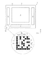
図1において、液晶表示装置1には、四角形状に形成されたガラス基板(以下単に、「基板」という。)2が備えられて、本実施形態では、その基板2の長手方向をX矢印方向とし、X矢印方向と直交する方向をY矢印方向とする。
DESCRIPTION OF EMBODIMENTS Hereinafter, embodiments embodying the present invention will be described with reference to FIGS. First, a liquid crystal display device having an identification code formed using the pattern forming method of the present invention will be described.
In FIG. 1, the liquid
基板2の一側面(表面2a)であって、その略中央位置には、液晶分子を封入した四角形状の表示部3が形成されて、その表示部3の外側には、走査線駆動回路4及びデータ線駆動回路5が形成されている。液晶表示装置1は、これら走査線駆動回路4の供給する走査信号と、データ線駆動回路5の供給するデータ信号に基づいて、前記表示部3内の液晶分子の配向状態を制御するようになっている。そして、液晶表示装置1は、図示しない照明装置からの平面光を液晶分子の配向状態によって変調して、表示部3の領域に所望の画像を表示するようになっている。
On one side surface (
基板2の表面2aであって、その左側下隅には、液晶表示装置1の識別コード10が形成されている。識別コード10は、一辺が約1mmの正方形で形成されたコード形成領域Sに形成されている。コード形成領域Sは、8行×8列のデータセルCに仮想分割されて、そのデータセルCの領域に、外径がデータセルCの一辺の長さに相当する半球状のパターンとしてのドットDが選択的に形成されている。本実施形態では、ドットDの形成されたデータセルCを「黒セルC1」とし、ドットDの形成されないデータセルCを「白セルC0」という。また、各黒セルC1の中心位置を「目標吐出位置P」とし、データセルCの一辺の長さを「セル幅W」という。
An
ドットDは、パターン形成材料としての金属微粒子(例えば、ニッケル微粒子やマンガン微粒子)を分散媒に分散させた液状体F(図4参照)の液滴Fbを黒セルC1に吐出し、黒セルC1に着弾した液滴Fbを乾燥及び焼成させることによって形成されている。この液滴Fbの乾燥・焼成は、レーザ光B(図4参照)を照射することによって行われる。尚、本実施形態では、液滴Fbを乾燥・焼成することによってドットDを形成するようにしているが、これに限らず、例えばレーザ光Bの乾燥のみによって形成するようにしてもよい。 The dot D ejects a droplet Fb of a liquid F (see FIG. 4) in which metal fine particles (for example, nickel fine particles and manganese fine particles) as a pattern forming material are dispersed in a dispersion medium, to the black cell C1. It is formed by drying and firing the droplet Fb landed on the surface. The drying and firing of the droplets Fb are performed by irradiating with laser light B (see FIG. 4). In this embodiment, the dots D are formed by drying and firing the droplets Fb. However, the present invention is not limited to this, and the droplets may be formed only by drying the laser beam B, for example.
そして、識別コード10は、各データセルC内のドットDの有無によって、液晶表示装置1の製品番号やロット番号等を再現できるようになっている。
次に、前記識別コード10を形成するための液滴吐出装置について説明する。
The
Next, a droplet discharge device for forming the
図2に示すように、液滴吐出装置20には、その長手方向がX矢印方向に沿う直方体形状に形成された基台21が備えられている。基台21の上面には、X矢印方向に延びる1対の案内溝22が形成されて、X軸モータMX(図5参照)に駆動連結される基板ステージ23が、その案内溝22に案内されてX矢印方向及び反X矢印方向に直動するようになっている。基板ステージ23の上面には、図示しない吸引式のチャック機構が設けられて、その上面に載置される基板2が、表面2a(コード形成領域S)を上側にして位置決め
固定されるようになっている。本実施形態では、最も反X矢印方向に位置する基台21の配置位置(図2の実線)を往動位置とし、最もX矢印方向の配置位置(図2に示す2点鎖線)を復動位置という。
As shown in FIG. 2, the droplet discharge device 20 is provided with a base 21 formed in a rectangular parallelepiped shape whose longitudinal direction is along the X arrow direction. A pair of
基台21のY矢印方向両側には、門型に形成された案内部材24が配設されている。案内部材24の上側には、液状体Fを収容する収容タンク25が配設されて、収容する液状体Fを液滴吐出ヘッド(以下単に、「吐出ヘッド」という。)30に導出するようになっている。案内部材24の下側には、Y矢印方向に延びる上下一対の案内レール26がY矢印方向全幅にわたり形成されて、Y軸モータMY(図5参照)に駆動連結されるキャリッジ27が、その案内レール26に沿ってY矢印方向及び反Y矢印方向に直動するようになっている。本実施形態では、最も反Y矢印方向側に位置するキャリッジ27の配置位置(図2に示す実線)を往動位置とし、最もY矢印方向側に位置する配置位置(図2に示す2点鎖線)を復動位置という。
On both sides of the base 21 in the Y arrow direction, guide
そのキャリッジ27の下側には、吐出ヘッド30が搭載されている。図3は、吐出ヘッド30を基板2側から見た斜視図である。
図3に示すように、吐出ヘッド30の基板2側(図3における上側)には、反射部材を構成するノズルプレート31が備えられている。ノズルプレート31は、その下面(図3における上面:反射面31a)がレーザ光Bを反射する鏡面に研磨されたステンレス等の板部材であって、その反射面31aが基板2の表面2aと平行に配設されている。
A
As shown in FIG. 3, a
反射面31aの表面(下面:図3における上面)には、レーザ光Bを透過する数百nm程度のシリコーン樹脂やフッ素樹脂等の重合膜(撥液膜31b)がコーティングされて、液状体Fに対する撥液性を発現するようになっている。尚、本実施形態では、撥液膜31bを反射面31aに直接コーティングする構成にしたが、これに限らず、反射面31aと撥液膜31bとの間の密着性を向上するために、シランカップリング剤等からなる数nmの密着層を、反射面31aと撥液膜31bとの間に介在させる構成にしてもよい。
The surface (lower surface: upper surface in FIG. 3) of the
ノズルプレート31には、吐出口を構成する複数のノズルNが、Y矢印方向に沿う列状に等間隔で形成されている。ノズルNは、そのY矢印方向に沿う形成ピッチが目標吐出位置Pの形成ピッチと同じ幅(セル幅W)で形成されて、図4に示すように、それぞれ基板2の法線方向(Z矢印方向)に沿って貫通形成されている。本実施形態では、表面2a上の位置であって、各ノズルNの反Z矢印方向に相対する位置を、それぞれ「着弾位置PF」という。
In the
各ノズルNのZ矢印方向には、キャビティ32が形成されている。各キャビティ32は、それぞれ対応する連通孔33と各連通孔33に共通する供給路34を介して収容タンク25に連通して、収容タンク25が導出する液状体Fを、それぞれ対応するノズルN内に供給するようになっている。各キャビティ32の上側には、Z矢印方向及び反Z矢印方向(上下方向)に振動可能な振動板35が貼り付けられて、キャビティ32内の容積を拡大・縮小するようになっている。振動板35の上側には、各ノズルNに対応する複数の圧電素子PZが配設されて、それぞれ圧電素子PZを駆動制御するための信号(圧電素子駆動電圧VDP:図5参照)を受けて上下方向に収縮・伸張し、対応する振動板35をZ矢印方向及び反Z矢印方向に振動させるようになっている。
In the direction of the arrow Z of each nozzle N, a
そして、基板ステージ23をX矢印方向に搬送して、黒セルC1(目標吐出位置P)が着弾位置PFと相対するタイミングで、圧電素子PZを収縮・伸張させる。すると、対応するキャビティ32内の容積が拡大・縮小して、縮小した容積に対応する液状体Fが、対応するノズルNから液滴Fbとして吐出される。ノズルNから吐出された液滴Fbは、略反Z矢印方向に飛行して、対応するノズルNの直下に位置する目標吐出位置P(着弾位置
PF)に着弾する。目標吐出位置Pに着弾した液滴Fbは、搬送時間の経過とともに直ちに濡れ広がって、乾燥するためのサイズ(本実施形態では、前記セル幅W)にまで拡大する。本実施形態では、液滴Fbの中心位置(目標吐出位置P)であって、液滴Fbの外径がセル幅Wになる位置を、「照射位置PT」という。
Then, the
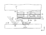
図4に示すように、吐出ヘッド30のX矢印方向側には、レーザ光源としての複数の半導体レーザLDを搭載したレーザヘッド36が配設されている。各半導体レーザLDは、それぞれノズルNのX矢印方向側に配設されて、液状体F(分散媒や金属微粒子等)の吸収波長に対応する波長領域のレーザ光Bを出射するようになっている。各半導体レーザLDの基板2側には、それぞれ半導体レーザLDからのレーザ光Bを平行光束にするコリメータ37と、コリメータ37からのレーザ光を収束して基板2の表面2aに導く集光レンズ38が配設されている。そして、これらコリメータ37と集光レンズ38からなる光学系によって、表面2aの法線方向(Z矢印方向)に対し、所定の角度だけ傾斜する光軸A1が形成されている。
As shown in FIG. 4, a
本実施形態では、Z矢印方向に対する光軸A1の角度を、「入射角θ1」とし、光軸A1が表面2aと交差する位置を、「基板反射位置PR」という。
ここで、本実施形態の入射角θ1は、照射するレーザ光Bが表面2a(基板反射位置PR)で全反射される最小の角度、すなわち臨界角に設定されて、基板反射位置PRで全反射したレーザ光Bを、ノズルプレート31の反射面31aに導く位置に設定されている。しかも、本実施形態の基板反射位置PRは、反射面31aで全反射する基板反射位置PRからのレーザ光Bを前記照射位置PTまで導く位置に設定されている。すなわち、レーザヘッド36からのレーザ光Bは、上記する入射角θ1と基板反射位置PRによって、基板2(表面2a)側の反射とノズルプレート31(反射面31a)側の反射を経て、照射位置PTに照射されるようになっている。
In the present embodiment, the angle of the optical axis A1 with respect to the Z arrow direction is “incident angle θ1”, and the position where the optical axis A1 intersects the
Here, the incident angle θ1 of the present embodiment is set to a minimum angle at which the irradiated laser beam B is totally reflected at the
本実施形態では、照射位置PTに照射されるレーザ光BのZ矢印方向に対する角度を、「照射角θ2」という。尚、本実施形態では、基板2の表面2aとノズルプレート31の反射面31aが平行に配設されて、照射角θ2が前記入射角θ1と等しくなるように構成されている。
In the present embodiment, the angle of the laser beam B irradiated to the irradiation position PT with respect to the Z arrow direction is referred to as “irradiation angle θ2”. In the present embodiment, the
従って、本実施形態の液滴吐出装置20では、基板2側の反射とノズルプレート31側の反射を介する分だけ、照射角θ2を小さくすることができ、照射位置PTにおけるレーザ光Bの光断面(ビームスポット)の拡大を抑制することができる。その結果、液滴Fbに照射するレーザ光Bの照射強度の向上と照射位置の位置精度の向上を図ることができる。尚、本実施形態のビームスポットは、前記データセルC(液滴Fb)を覆う略円形に成形されているが、これに限られるものではない。
Therefore, in the droplet discharge device 20 of the present embodiment, the irradiation angle θ2 can be reduced by the amount corresponding to the reflection on the
そして、目標吐出位置Pに着弾した液滴Fbを照射位置PTに搬送して、レーザ光Bを出射するための駆動信号(レーザ駆動電圧VDL:図5参照)を対応する半導体レーザLDに供給する。すると、所定の強度のレーザ光Bが、対応する半導体レーザLDから出射されて、出射されたレーザ光Bが、基板2とノズルプレート31に反射されて照射位置PTの液滴Fb、すなわちセル幅Wに相対する外径の液滴Fbに照射される。
Then, the droplet Fb landed on the target discharge position P is conveyed to the irradiation position PT, and a drive signal (laser drive voltage VDL: see FIG. 5) for emitting the laser beam B is supplied to the corresponding semiconductor laser LD. . Then, a laser beam B having a predetermined intensity is emitted from the corresponding semiconductor laser LD, and the emitted laser beam B is reflected by the
レーザ光Bの照射された液滴Fbは、その分散媒の蒸発によって濡れ広がりが抑制されて、外径がセル幅Wからなる半球状パターンとして瞬時に固化される。固化された液滴Fbは、連続するレーザ光Bの照射によってその金属微粒子が焼成されて、外径がセル幅WからなるドットDとして基板2の表面2aに固着する。
The droplet Fb irradiated with the laser beam B is suppressed from wetting and spreading by evaporation of the dispersion medium, and is instantly solidified as a hemispherical pattern having an outer diameter of the cell width W. The solidified droplets Fb are baked with fine metal particles by continuous irradiation with the laser beam B, and are fixed to the
次に、上記のように構成した液滴吐出装置20の電気的構成を図5に従って説明する。
図5において、制御部41は、CPU、RAM、ROM等を備え、ROM等に格納された各種データ(例えば、基板ステージ23の移動速度やセル幅W等)と各種制御プログラム(例えば、識別コード10を形成するための識別コード形成プログラム)に従って、基板ステージ23を移動させて、液滴吐出ヘッド30及びレーザヘッド36を駆動させる。
Next, the electrical configuration of the droplet discharge device 20 configured as described above will be described with reference to FIG.
5, the
制御部41には、起動スイッチ、停止スイッチ等の操作スイッチを有した入力装置42が接続されて、入力装置42からの各スイッチの操作による操作信号が入力されるようになっている。また、制御部41には、識別コード10の画像が既定形式の描画データIaとして入力されるようになっている。そして、制御部41は、入力装置42からの描画データIaを受けて、基板2に識別コード10を作成するためのビットマップデータBMDを生成するようになっている。詳述すると、制御部41は、描画データIaに所定の展開処理を施して、二次元描画平面(コード形成領域S)上における各データセルCに、液滴Fbを吐出するか否かを示すビットマップデータBMDを生成してRAMに格納する。このビットマップデータBMDは、データセルCに対応した8×8ビットのデータであり、各ビットの値(0あるいは1)に応じて、圧電素子PZのオンあるいはオフ(液滴Fbを吐出するか否か)を規定するものである。
An
また、制御部41は、描画データIaに、前記ビットマップデータBMDの展開処理と異なる展開処理を施して、各圧電素子PZを駆動するための圧電素子駆動電圧VDPを生成し、半導体レーザLDを駆動するためのレーザ駆動電圧VDLを生成する。
Further, the
制御部41には、X軸モータ駆動回路43及びY軸モータ駆動回路44が接続されて、X軸モータ駆動回路43及びY軸モータ駆動回路44に、それぞれX軸モータ駆動制御信号及びY軸モータ駆動制御信号を出力するようになっている。X軸モータ駆動回路43は、制御部41からのX軸モータ駆動制御信号に応答して、基板ステージ23を往復移動させるX軸モータMXを正転又は逆転させるようになっている。Y軸モータ駆動回路44は、制御部41からのY軸モータ駆動制御信号に応答して、キャリッジ27を往復移動させるY軸モータMYを正転又は逆転させるようになっている。
An X-axis
制御部41には、基板2の端縁を検出可能な撮像機能等を備えた基板検出装置45が接続されて、基板検出装置45の出力する検出信号を受けて、ノズルNの直下を通過する基板2の位置を算出するようになっている。
The
制御部41には、X軸モータ回転検出器46及びY軸モータ回転検出器47が接続されて、X軸モータ回転検出器46及びY軸モータ回転検出器47からの検出信号が入力されるようになっている。
An X-axis
制御部41は、X軸モータ回転検出器46からの検出信号に基づいて、X軸モータMXの回転方向及び回転量を検出し、吐出ヘッド30に対する基板2の移動方向及び移動量を演算するようになっている。そして、制御部41は、各データセルCの中心位置が着弾位置PFに位置するタイミングで、後述する吐出ヘッド駆動回路48及びレーザ駆動回路49に、吐出タイミング信号SGを出力するようになっている。
The
制御部41は、Y軸モータ回転検出器47からの検出信号に基づいて、Y軸モータMYの回転方向及び回転量を検出し、液滴吐出ヘッド30に対する基板2のY矢印方向の移動方向及び移動量を演算するようになっている。そして、制御部41は、各ノズルNに対応する着弾位置PFを目標吐出位置Pの移動経路上に配置するようになっている。
Based on the detection signal from the Y-axis
制御部41には、吐出ヘッド駆動回路48が接続されている。制御部41は、1スキャン(基板2の1回の往動もしくは復動)分のビットマップデータBMDを所定のクロック
信号に同期させた信号(ヘッド制御信号SCH)を生成して、生成したヘッド制御信号SCHを吐出ヘッド駆動回路48に順次シリアル転送するようになっている。また、制御部41は、所定のクロック信号に同期させた圧電素子駆動電圧VDPを吐出ヘッド駆動回路48に出力するようになっている。吐出ヘッド駆動回路48は、制御部41からシリアル転送されるヘッド制御信号SCHを各圧電素子PZに対応させてシリアル/パラレル変換する。そして、吐出ヘッド駆動回路48は、制御部41からの吐出タイミング信号SGを受けると、ヘッド制御信号SCHに応じた圧電素子PZに圧電素子駆動電圧VDPを供給するようになっている。すなわち、制御部41は、吐出ヘッド駆動回路48を介して、ヘッド制御信号SCH(ビットマップデータBMD)に対応したノズルNから、液滴Fbを吐出させるようになっている。
A discharge
制御部41は、レーザ駆動回路49が接続されている。制御部41は、前記ヘッド制御信号SCHをレーザ駆動回路49に順次シリアル転送するとともに、所定のクロック信号に同期させたレーザ駆動電圧VDLを出力するようになっている。レーザ駆動回路49は、制御部41からシリアル転送されるヘッド制御信号SCHを各半導体レーザLDに対応させてシリアル/パラレル変換する。そして、レーザ駆動回路49は、制御部41からの吐出タイミング信号SGを受けると、所定の時間だけ待機して、ヘッド制御信号SCHに応じた半導体レーザLDにレーザ駆動電圧VDLを供給するようになっている。すなわち、制御部41は、レーザ駆動回路49を介して、液滴Fbを吐出したノズルNに対応する半導体レーザLDからレーザ光Bを出射させるようになっている。
The
本実施形態では、吐出タイミング信号SGを受けたレーザ駆動回路49がレーザ駆動電圧VDLを供給するまでの時間を「待機時間」とし、着弾位置PFの液滴Fbが照射位置PTに到達するまでの時間に設定されている。すなわち、レーザ駆動回路49は、着弾した液滴Fbの外径がセル幅Wになるまで待機し、液滴Fbの外径がセル幅Wになるタイミングで、対応する半導体レーザLDからレーザ光Bを出射するようになっている。
In the present embodiment, the time until the
次に、液滴吐出装置20を使って識別コード10を形成する方法について説明する。
まず、図2に示すように、往動位置に位置する基板ステージ23上に、基板2を、その表面2aが上側になるように配置固定する。このとき、基板2のX矢印方向側の辺は、案内部材24より反X矢印方向側に配置されている。
Next, a method for forming the
First, as shown in FIG. 2, the
この状態から、入力装置42を操作して描画データIaを制御部41に入力する。すると、制御部41は、描画データIaに基づくビットマップデータBMDを生成して、圧電素子を駆動するための圧電素子駆動電圧VDPと半導体レーザLDを駆動するためのレーザ駆動電圧VDLを生成する。
From this state, the
圧電素子駆動電圧VDP及びレーザ駆動電圧VDLを生成すると、制御部41は、Y軸モータMYを駆動制御して、キャリッジ27を往動位置からY矢印方向に搬送し、各目標吐出位置PのX矢印方向に、対応するノズルN(着弾位置PF)が位置するように、キャリッジ27をセットする。キャリッジ27をセットすると、制御部41は、X軸モータMXを駆動制御して、基板2をX矢印方向に搬送する。
When the piezoelectric element drive voltage VDP and the laser drive voltage VDL are generated, the
やがて、基板検出装置45が基板2のX矢印方向側端部の位置を検出すると、制御部41は、X軸モータ回転検出器46からの検出信号に基づいて、最もX矢印方向側(1列目)の黒セルC1(目標吐出位置P)が着弾位置PFまで搬送されたか否か判断する。
Eventually, when the
この間、制御部41は、吐出ヘッド駆動回路48に、圧電素子駆動電圧VDP及びヘッド制御信号SCHを出力し、レーザ駆動回路49に、レーザ駆動電圧VDL及びヘッド制御信号SCHを出力し、これら吐出ヘッド駆動回路48及びレーザ駆動回路49に、それ
ぞれ吐出タイミング信号SGを出力するタイミングを待つ。
During this time, the
そして、1列目の黒セルC1(目標吐出位置P)が着弾位置PFに搬送されると、制御部41は、吐出ヘッド駆動回路48とレーザ駆動回路49に吐出タイミング信号SGを出力する。
When the black cell C1 (target discharge position P) in the first column is conveyed to the landing position PF, the
吐出タイミング信号SGを出力すると、制御部41は、吐出ヘッド駆動回路48を介して、ヘッド制御信号SCHに応じた圧電素子PZに、それぞれ圧電素子駆動電圧VDPを供給し、ヘッド制御信号SCHに対応したノズルNから、一斉に液滴Fbを吐出させる。吐出された液滴Fbは、対応する着弾位置PF(目標吐出位置P)に着弾し、着弾位置PFから照射位置PTまで搬送される間に、その外径がセル幅Wとなる。
When the ejection timing signal SG is output, the
また、吐出タイミング信号SGを出力すると、制御部41は、レーザ駆動回路49を介して、半導体レーザLDを待機時間だけ待機させ、その後に、ヘッド制御信号SCHに応じた半導体レーザLDに、それぞれレーザ駆動電圧VDLを供給する。そして、制御部41は、対応する半導体レーザLDから、一斉にレーザ光Bを出射させる。一斉に出射されたレーザ光Bは、基板2(表面2a)とノズルプレート31(反射面31a)に反射されて、照射角θ2(入射角θ1:臨界角)で照射位置PTの液滴Fb、すなわちセル幅Wの外径を有した液滴Fbに照射される。レーザ光Bの照射された液滴Fbは、分散媒の蒸発と金属微粒子の焼成によって、その外径がセル幅WのドットDとして基板2の表面2aに固着される。これによって、1行目の黒セルC1内に、そのセル幅Wに整合したドットDが形成される。
When the ejection timing signal SG is output, the
以後、同様に、制御部41は、基板2をX矢印方向に搬送して、各目標吐出位置Pが着弾位置PFに到達する毎に、対応するノズルNから液滴Fbを一斉に吐出する。そして、黒セルC1に着弾した液滴Fbがセル幅Wになるタイミングで、一斉に照射角θ2のレーザ光Bを照射して、コード形成領域Sの全てドットDを形成する。
Thereafter, similarly, the
次に、上記のように構成した本実施形態の効果を以下に記載する。
(1)上記実施形態によれば、吐出ヘッド30のX矢印方向にレーザヘッド36を設けて、レーザヘッド36からのレーザ光Bを、表面2aに対する臨界角(入射角θ1)で基板反射位置PRに出射し、吐出ヘッド30側に全反射させるようにした。
Next, effects of the present embodiment configured as described above will be described below.
(1) According to the above embodiment, the
また、ノズルプレート31の基板2側にレーザ光Bを反射する反射面31aを設けて、基板反射位置PRからのレーザ光Bを、表面2a上の照射位置PTに照射角θ2(入射角θ1:臨界角)で反射させるようにした。
Further, a
従って、基板2側の反射とノズルプレート31側の反射を介する分だけ、照射角θ2を小さくすることができ、照射位置PTの液滴Fbに対して、表面2aの法線方向(Z矢印方向)に近いレーザ光Bを照射することができる。その結果、照射位置PTにおけるレーザ光Bの光断面(ビームスポット)の拡大を抑制することができ、液滴Fbに照射するレーザ光Bの照射強度の向上と照射位置の位置精度の向上を図ることができる。ひいては、ドットDの形状制御性を向上することができる。
Therefore, the irradiation angle θ2 can be reduced by an amount corresponding to the reflection on the
(2)上記実施形態によれば、反射部材をノズルプレート31(反射面31a)で構成するようにした。従って、反射部材を別途設ける場合に比べて、液滴吐出装置20の部材点数を削減することができ、より簡便な構成によって、照射強度の向上と照射位置の位置精度の向上を図ることができる。
(2) According to the above embodiment, the reflecting member is constituted by the nozzle plate 31 (reflecting
しかも、着弾位置PF(基板2)とノズルN(吐出ヘッド30)との間の距離(プラテ
ンギャップ)を変更することなく、基板反射位置PRからのレーザ光Bを照射位置PTに反射させることができる。その結果、プラテンギャップを増大させる、すなわち液滴Fbの着弾位置の精度を低下させることなく、照射強度と照射位置の位置精度の向上を図ることができる。
Moreover, the laser beam B from the substrate reflection position PR can be reflected to the irradiation position PT without changing the distance (platen gap) between the landing position PF (substrate 2) and the nozzle N (ejection head 30). it can. As a result, it is possible to improve the irradiation intensity and the position accuracy of the irradiation position without increasing the platen gap, that is, without reducing the accuracy of the landing position of the droplet Fb.
(3)上記実施形態によれば、反射面31aの表面に、レーザ光Bを透過して液状体Fを撥液する撥液膜31bをコーティングするようにした。従って、ノズルNから吐出されたミスト状の液状体Fを撥液することができ、反射面31aの汚染を抑制することができる。その結果、反射面31aの光学的機能の劣化を抑制することができ、照射強度や照射位置の位置精度の安定化を図ることができる。
(3) According to the above embodiment, the surface of the
なお、上記実施形態は以下のように変更してもよい。
・上記実施形態では、基板2の表面2aでレーザ光Bを反射するようにした。これに限らず、例えば基板2の裏面やその裏面側に配設される基板ステージ23によって反射する構成にしてもよく、吐出ヘッド30に対する基板2側で反射する構成であればよい。
In addition, you may change the said embodiment as follows.
In the above embodiment, the laser beam B is reflected on the
・上記実施形態では、ノズルプレート31の反射面31aを表面2aと平行に配設するようにした。これに限らず、例えば図6に示すように、ノズルプレート31の反射面31aを、レーザヘッド36側の空間が広がるように、表面2aに対して傾斜角θ3だけ傾斜させるようにしてもよい。これによれば、照射位置PTに照射するレーザ光Bの照射角θ2を、傾斜角θ3の分だけ、さらに小さくすることができ、レーザ光Bの照射強度や照射位置の位置精度を、さらに向上することができる。
In the above embodiment, the reflecting
あるいは、図7に示すように、反射面31aを設けることなく、ノズルプレート31の基板2側に反射部材としての反射ミラー39を配設し、基板反射位置PRからのレーザ光Bを反Z矢印方向に反射して照射位置PTに導く構成にしてもよい。これによれば、照射角θ2を0度にして、レーザ光Bの照射強度や照射位置の位置精度を、さらに向上することができる。
Alternatively, as shown in FIG. 7, a
尚、図7では、反射ミラー39をノズルNのX矢印方向に配設しているが、これに限らず、反X矢印方向に配設してもよく、照射角θ2を小さくする位置であればよい。
・上記実施形態では、ノズルプレート31の反射面31aを平面で構成するようにした。これに限らず、例えば図8に示すように、反射面31aを凹曲面Vに形成して、表面2aで反射される互いに平行なレーザ光Bを照射位置PTの領域に収束するようにしてもよい。これによれば、複数の異なる基板反射位置PRからのレーザ光Bを照射位置PTに導くことができ、基板反射位置PRに位置ズレを来たす場合であっても、確実に、レーザ光Bを照射位置PTに導くことができる。その結果、レーザ光Bの照射強度や照射位置の位置精度を、より確実に向上することができる。
In FIG. 7, the
In the above embodiment, the reflecting
尚、図8では、反射面31aのX矢印方向端部を凹曲面Vに形成しているが、これに限らず、反射面31aの全体を凹曲面状にしてもよく、表面2aからのレーザ光Bを照射位置PTに収束可能にするものであればよい。
・上記実施形態では、表面2aとノズルプレート31(反射面31a)の双方で、それぞれ1回だけレーザ光Bを反射する構成にした。これに限らず、表面2aとノズルプレート31の間で多重反射させるように構成してもよい。
・上記実施形態では、液滴Fbの領域に照射するレーザ光Bによって、液滴Fbを乾燥・焼成する構成にした。これに限らず、例えば照射するレーザ光Bのエネルギーによって、液滴Fbを所望の方向に流動させる構成にしてもよく、あるいは液滴Fbの外縁のみに照射して液滴Fbをピニングする構成にしてもよい。すなわち、液滴Fbの領域に照射するレーザ光Bによってパターンを形成する構成であればよい。
・上記実施形態では、レーザ光源を半導体レーザLDで具体化したが、これに限らず、例えば炭酸ガスレーザやYAGレーザであってもよく、着弾した液滴Fbを乾燥可能な波長のレーザ光Bを出力するレーザであればよい。
・上記実施形態では、液滴Fbによって半円球状のドットDを形成する構成にしたが、これに限らず、例えば、楕円形状のドットや線状のパターンを形成する構成であってもよい。
・上記実施形態では、パターンを識別コード10のドットDに具体化した。これに限らず、例えばパターンを、液晶表示装置1や、平面状の電子放出素子を備えて同素子から放出された電子による蛍光物質の発光を利用した電界効果型装置(FEDやSED等)の絶縁膜や金属配線等、各種パターンに具体化してもよく、着弾した液滴Fbの領域にレーザ光を照射して形成するパターンであればよい。
In FIG. 8, the end of the reflecting
In the above embodiment, the laser beam B is reflected only once by both the
In the above embodiment, the droplet Fb is dried and fired by the laser beam B irradiated to the region of the droplet Fb. For example, the configuration may be such that the droplet Fb flows in a desired direction by the energy of the irradiated laser beam B, or the droplet Fb is pinned by irradiating only the outer edge of the droplet Fb. May be. That is, any pattern may be used as long as the pattern is formed by the laser beam B irradiated to the region of the droplet Fb.
In the above embodiment, the laser light source is embodied by the semiconductor laser LD. However, the laser light source is not limited to this. For example, a carbon dioxide laser or a YAG laser may be used. Any laser can be used.
In the above embodiment, the hemispherical dots D are formed by the droplets Fb. However, the present invention is not limited to this. For example, an oval dot or a linear pattern may be formed.
In the above embodiment, the pattern is embodied as the dot D of the
・上記実施形態では、基板を液晶表示装置1の基板2に具体化したが、これに限らず、例えばシリコン基板やフレキシブル基板、あるいは金属基板等であってもよい。
In the above embodiment, the substrate is embodied as the
2…基板、10…識別コード、20…液滴吐出装置、30…液滴吐出ヘッド、31…反射部材を構成するノズルプレート、31a…反射面、31b…撥液膜、B…レーザ光、D…パターンとしてのドット、Fb…液滴、LD…レーザ光源としての半導体レーザ、N…吐出口を構成するノズル。
DESCRIPTION OF
Claims (7)
前記基板に向けて出射した前記レーザ光を、前記吐出口の近傍に設けられた反射部材に向けて前記基板により反射させ、前記反射部材により反射された前記レーザ光を、前記液滴が着弾した前記基板に向けて反射させ、
前記基板に向けて出射した前記レーザ光の光路と、前記基板に対する法線と、のなす角度を入射角とし、
前記液滴に向けて反射された前記レーザ光の光路と、前記基板の法線と、のなす角度を照射角としたとき、
前記照射角を前記入射角よりも小さくするように、前記レーザ光を照射する
ことを特徴とするパターン形成方法。 In a pattern forming method of forming a pattern by discharging a droplet including a pattern forming material from a discharge port of a droplet discharge head opposed to a substrate, and irradiating the region of the droplet landed on the substrate with a laser beam.
The laser beam emitted toward the substrate, before SL in the reflecting member provided in the vicinity of the discharge port direction Ke is reflected by said substrate, said laser beam reflected by the reflecting member, before Kiekishizuku Is reflected toward the substrate that has landed ,
The angle formed by the optical path of the laser beam emitted toward the substrate and the normal to the substrate is the incident angle,
When the angle formed by the optical path of the laser beam reflected toward the droplet and the normal line of the substrate is an irradiation angle,
The pattern forming method , wherein the laser beam is irradiated so that the irradiation angle is smaller than the incident angle .
前記吐出口の近傍に設けられて、前記基板から反射した前記レーザ光を、前記基板に着弾した前記液滴の領域に反射する反射部材を備えてなり、
前記レーザ光源から出射するレーザ光の光路と、前記基板に対する法線と、のなす角度を入射角とし、
前記液滴に向けて反射された前記レーザ光の光路と、前記基板に対する法線と、のなす角度を照射角とすると、
前記照射角が前記入射角よりも小さい
ことを特徴とする液滴吐出装置。 In a liquid droplet ejection apparatus comprising: a liquid droplet ejection head that ejects liquid droplets from an ejection port facing the substrate; and a laser light source that emits laser light toward the substrate.
A reflection member provided in the vicinity of the discharge port and configured to reflect the laser beam reflected from the substrate to a region of the droplet landed on the substrate ;
The angle formed by the optical path of the laser beam emitted from the laser light source and the normal to the substrate is the incident angle,
When the angle formed by the optical path of the laser beam reflected toward the droplet and the normal to the substrate is an irradiation angle,
The droplet discharge apparatus, wherein the irradiation angle is smaller than the incident angle .
前記反射部材は、前記吐出口の形成されたノズルプレートであることを特徴とする液滴吐出装置。 The droplet discharge device according to claim 2,
The liquid droplet ejection apparatus, wherein the reflection member is a nozzle plate in which the ejection port is formed.
前記反射部材は、前記レーザ光を透過して前記液滴を撥液する撥液膜で被覆されたことを特徴とする液滴吐出装置。 In the droplet discharge device according to claim 2 or 3,
The liquid droplet ejection apparatus, wherein the reflecting member is covered with a liquid repellent film that transmits the laser light and repels the liquid droplets.
前記反射部材は、前記基板からの前記レーザ光を前記基板の略法線方向に沿って反射する反射面を備えたことを特徴とする液滴吐出装置。 In the liquid droplet ejection device according to any one of claims 2 to 4,
The droplet ejection apparatus, wherein the reflecting member includes a reflecting surface that reflects the laser light from the substrate along a substantially normal direction of the substrate.
前記反射部材は、前記基板からの前記レーザ光を前記液滴の領域に収束する反射面を備えたことを特徴とする液滴吐出装置。 In the liquid droplet ejection device according to any one of claims 2 to 5,
The liquid droplet ejection apparatus, wherein the reflection member includes a reflection surface that converges the laser light from the substrate onto a region of the liquid droplet.
前記レーザ光源は、出射した前記レーザ光を前記基板で全反射することを特徴とする液滴吐出装置。 In the liquid droplet ejection device according to any one of claims 2 to 6,
The droplet discharge device, wherein the laser light source totally reflects the emitted laser light on the substrate.
Priority Applications (5)
| Application Number | Priority Date | Filing Date | Title |
|---|---|---|---|
| JP2005291559A JP4400542B2 (en) | 2005-10-04 | 2005-10-04 | Pattern forming method and droplet discharge apparatus |
| TW095135819A TW200722291A (en) | 2005-10-04 | 2006-09-27 | Method for forming a pattern and liquid ejection apparatus |
| CNA2006101414705A CN1944050A (en) | 2005-10-04 | 2006-09-29 | Method for forming a pattern and liquid ejection apparatus |
| KR1020060095883A KR100778427B1 (en) | 2005-10-04 | 2006-09-29 | Method for forming a pattern and liquid ejection apparatus |
| US11/541,939 US20070076077A1 (en) | 2005-10-04 | 2006-10-02 | Method for forming a pattern and liquid ejection apparatus |
Applications Claiming Priority (1)
| Application Number | Priority Date | Filing Date | Title |
|---|---|---|---|
| JP2005291559A JP4400542B2 (en) | 2005-10-04 | 2005-10-04 | Pattern forming method and droplet discharge apparatus |
Publications (2)
| Publication Number | Publication Date |
|---|---|
| JP2007098283A JP2007098283A (en) | 2007-04-19 |
| JP4400542B2 true JP4400542B2 (en) | 2010-01-20 |
Family
ID=37901490
Family Applications (1)
| Application Number | Title | Priority Date | Filing Date |
|---|---|---|---|
| JP2005291559A Expired - Fee Related JP4400542B2 (en) | 2005-10-04 | 2005-10-04 | Pattern forming method and droplet discharge apparatus |
Country Status (5)
| Country | Link |
|---|---|
| US (1) | US20070076077A1 (en) |
| JP (1) | JP4400542B2 (en) |
| KR (1) | KR100778427B1 (en) |
| CN (1) | CN1944050A (en) |
| TW (1) | TW200722291A (en) |
Families Citing this family (2)
| Publication number | Priority date | Publication date | Assignee | Title |
|---|---|---|---|---|
| JP2007313499A (en) * | 2006-04-27 | 2007-12-06 | Seiko Epson Corp | Pattern formation method, drop jetting device, and circuit module |
| CN104759753B (en) * | 2015-03-30 | 2016-08-31 | 江苏大学 | The co-ordination of multisystem automatization improves the method for induced with laser cavitation reinforcement |
Family Cites Families (4)
| Publication number | Priority date | Publication date | Assignee | Title |
|---|---|---|---|---|
| JPH09173938A (en) * | 1995-12-22 | 1997-07-08 | Dainippon Screen Mfg Co Ltd | Treating liquid discharge device and method for adjusting gap between its discharge nozzle and substrate surface |
| US6561640B1 (en) * | 2001-10-31 | 2003-05-13 | Xerox Corporation | Systems and methods of printing with ultraviolet photosensitive resin-containing materials using light emitting devices |
| DE602004000595D1 (en) * | 2003-07-15 | 2006-05-18 | Konica Minolta Med & Graphic | Ink-jet printer with UV-curable ink |
| JP4305209B2 (en) * | 2004-02-16 | 2009-07-29 | セイコーエプソン株式会社 | Droplet discharge head inspection method, inspection apparatus, droplet discharge head, and droplet discharge apparatus |
-
2005
- 2005-10-04 JP JP2005291559A patent/JP4400542B2/en not_active Expired - Fee Related
-
2006
- 2006-09-27 TW TW095135819A patent/TW200722291A/en unknown
- 2006-09-29 CN CNA2006101414705A patent/CN1944050A/en active Pending
- 2006-09-29 KR KR1020060095883A patent/KR100778427B1/en not_active IP Right Cessation
- 2006-10-02 US US11/541,939 patent/US20070076077A1/en not_active Abandoned
Also Published As
| Publication number | Publication date |
|---|---|
| JP2007098283A (en) | 2007-04-19 |
| KR100778427B1 (en) | 2007-11-21 |
| KR20070038002A (en) | 2007-04-09 |
| US20070076077A1 (en) | 2007-04-05 |
| CN1944050A (en) | 2007-04-11 |
| TW200722291A (en) | 2007-06-16 |
Similar Documents
| Publication | Publication Date | Title |
|---|---|---|
| JP4363435B2 (en) | Pattern forming method and droplet discharge apparatus | |
| KR100870451B1 (en) | Droplet ejection apparatus and identification code | |
| US20070120932A1 (en) | Droplet ejection apparatus | |
| KR100765402B1 (en) | Method for forming a pattern and liquid ejection apparatus | |
| JP4297066B2 (en) | Droplet discharge device and droplet discharge head | |
| KR100759307B1 (en) | Liquid ejection apparatus | |
| JP4400541B2 (en) | Pattern forming method and droplet discharge apparatus | |
| JP2007117922A (en) | Pattern formation method and liquid droplet discharge apparatus | |
| JP4400542B2 (en) | Pattern forming method and droplet discharge apparatus | |
| JP4400540B2 (en) | Pattern forming method and droplet discharge apparatus | |
| JP4407684B2 (en) | Pattern forming method and droplet discharge apparatus | |
| JP2007105661A (en) | Pattern formation method and liquid droplet discharge apparatus | |
| JP4534809B2 (en) | Droplet discharge device | |
| JP2007098281A (en) | Pattern formation method and liquid drop delivery apparatus | |
| JP2006314931A (en) | Droplet discharging apparatus and pattern forming method | |
| JP2007108497A (en) | Pattern forming method and liquid drop discharging device | |
| JP4442677B2 (en) | Droplet drying method for droplet discharge device and droplet discharge device | |
| JP2006263560A (en) | Droplet discharge method and droplet discharge apparatus |
Legal Events
| Date | Code | Title | Description |
|---|---|---|---|
| A977 | Report on retrieval |
Free format text: JAPANESE INTERMEDIATE CODE: A971007 Effective date: 20090325 |
|
| A131 | Notification of reasons for refusal |
Free format text: JAPANESE INTERMEDIATE CODE: A131 Effective date: 20090707 |
|
| A521 | Request for written amendment filed |
Free format text: JAPANESE INTERMEDIATE CODE: A523 Effective date: 20090907 |
|
| TRDD | Decision of grant or rejection written | ||
| A01 | Written decision to grant a patent or to grant a registration (utility model) |
Free format text: JAPANESE INTERMEDIATE CODE: A01 Effective date: 20091006 |
|
| A01 | Written decision to grant a patent or to grant a registration (utility model) |
Free format text: JAPANESE INTERMEDIATE CODE: A01 |
|
| R150 | Certificate of patent or registration of utility model |
Free format text: JAPANESE INTERMEDIATE CODE: R150 |
|
| A61 | First payment of annual fees (during grant procedure) |
Free format text: JAPANESE INTERMEDIATE CODE: A61 Effective date: 20091019 |
|
| FPAY | Renewal fee payment (event date is renewal date of database) |
Free format text: PAYMENT UNTIL: 20121106 Year of fee payment: 3 |
|
| LAPS | Cancellation because of no payment of annual fees |