JP2007108497A - Pattern forming method and liquid drop discharging device - Google Patents
Pattern forming method and liquid drop discharging device Download PDFInfo
- Publication number
- JP2007108497A JP2007108497A JP2005300175A JP2005300175A JP2007108497A JP 2007108497 A JP2007108497 A JP 2007108497A JP 2005300175 A JP2005300175 A JP 2005300175A JP 2005300175 A JP2005300175 A JP 2005300175A JP 2007108497 A JP2007108497 A JP 2007108497A
- Authority
- JP
- Japan
- Prior art keywords
- irradiation
- droplet
- laser
- irradiation port
- opening
- Prior art date
- Legal status (The legal status is an assumption and is not a legal conclusion. Google has not performed a legal analysis and makes no representation as to the accuracy of the status listed.)
- Pending
Links
Images


Abstract
Description
本発明は、パターン形成方法及び液滴吐出装置に関する。 The present invention relates to a pattern forming method and a droplet discharge device.
従来、液晶表示装置やエレクトロルミネッセンス表示装置等の表示装置には、画像を表示するための基板が備えられている。この種の基板には、品質管理や製造管理を目的として、その製造元や製品番号等の製造情報をコード化した識別コード(例えば、2次元コード)が形成されている。こうした識別コードは、配列された多数のパターン形成領域(データセル)の一部に、パターンとしてのコードパターン(例えば、有色の薄膜や凹部等のドット)を備え、そのコードパターンの有無によって製造情報を再現可能にしている。 Conventionally, a display device such as a liquid crystal display device or an electroluminescence display device is provided with a substrate for displaying an image. On this type of substrate, an identification code (for example, a two-dimensional code) in which manufacturing information such as the manufacturer and product number is encoded is formed for the purpose of quality control and manufacturing control. Such an identification code includes a code pattern (for example, a dot such as a colored thin film or a concave portion) as a pattern in a part of a large number of arranged pattern formation regions (data cells), and manufacturing information depending on the presence or absence of the code pattern. Is made reproducible.
識別コードの形成方法には、金属箔にレーザ光を照射してコードパターンをスパッタ成膜するレーザスパッタ法や、研磨材を含んだ水を基板等に噴射してコードパターンを刻印するウォータージェット法が提案されている(特許文献1、特許文献2)。
The identification code is formed by laser sputtering that irradiates a metal foil with laser light to form a code pattern by sputtering, or water jet that engraves a code pattern by spraying water containing an abrasive onto a substrate or the like. Has been proposed (
しかし、上記レーザスパッタ法では、所望するサイズのコードパターンを得るために、金属箔と基板の間隙を、数〜数十μmに調整しなければならない。つまり、基板と金属箔の表面に対して非常に高い平坦性が要求され、しかも、これらの間隙をμmオーダの精度で調整しなければならない。その結果、識別コードを形成できる対象基板が制限されて、その汎用性を損なう問題を招いていた。また、ウォータージェット法では、基板の刻印時に、水や塵埃、研磨剤等が飛散するため、同基板を汚染する問題があった。 However, in the above laser sputtering method, the gap between the metal foil and the substrate must be adjusted to several to several tens of micrometers in order to obtain a code pattern having a desired size. That is, very high flatness is required for the surface of the substrate and the metal foil, and the gap between them must be adjusted with an accuracy of the order of μm. As a result, the target substrate on which the identification code can be formed is limited, causing a problem that the versatility is impaired. Further, the water jet method has a problem of contaminating the substrate because water, dust, abrasives, etc. are scattered when the substrate is engraved.
近年、こうした生産上の問題を解消する識別コードの形成方法として、インクジェット法が注目されている。インクジェット法では、金属微粒子を含む液滴を吐出口から吐出して、その液滴を乾燥させることによってコードパターンを形成する。そのため、識別コードを形成する基板の対象範囲を拡大することができ、同基板の汚染等を回避して識別コードを形成することができる。
しかしながら、上記インクジェット法では、液滴を乾燥することによってコードパターンを形成するために、基板の表面状態や液滴の表面張力等に応じて、以下の問題を招いていた。すなわち、基板に対する液滴の濡れ性が高くなると、基板に着弾した液滴は、基板表面に沿って直ちに濡れ広がる。そのため、液滴の乾燥に時間を要すると(例えば、100ミリ秒以上の時間を要すると)、着弾した液滴が基板表面で過剰に濡れ広がって、対応するデータセル内から食み出すようになる。その結果、コードパターンを読み取り不可能にして基板情報を損失する問題があった。 However, in the inkjet method, since the code pattern is formed by drying the droplets, the following problems are caused depending on the surface condition of the substrate, the surface tension of the droplets, and the like. In other words, when the wettability of the droplet with respect to the substrate increases, the droplet that has landed on the substrate immediately wets and spreads along the substrate surface. Therefore, when it takes time to dry the droplet (for example, when it takes 100 milliseconds or more), the landed droplet is excessively spread on the surface of the substrate so that it oozes out from the corresponding data cell. Become. As a result, there is a problem that the code pattern cannot be read and the board information is lost.
こうした問題は、液滴を吐出する液滴吐出装置にレーザ照射手段を搭載し、レーザ照射手段からのレーザ光を所望のサイズの液滴に照射する、すなわち所望のサイズの液滴を瞬時に乾燥することによって回避可能と考えられる。 These problems are caused by mounting a laser irradiation unit on a droplet discharge device that discharges droplets, and irradiating a droplet of a desired size with laser light from the laser irradiation unit, that is, drying a droplet of a desired size instantaneously. This is considered to be avoidable.
しかし、液滴吐出装置の空間には、液滴の吐出動作時に発生するミストや乾燥時の液滴から発生する蒸発成分が多量に浮遊している。そのため、液滴吐出装置にレーザ照射手段を搭載すると、レーザ光の光学系(特に、露出するレンズの光学面)に、上記するミスト
や蒸発成分が付着して、レーザ光の照射強度や照射位置を大きく変動させる虞があった。
However, in the space of the droplet discharge device, a large amount of mist generated during the droplet discharge operation and evaporation components generated from the droplet during drying are floating. For this reason, when a laser irradiation means is mounted on the droplet discharge device, the above-described mist or evaporation component adheres to the optical system of laser light (particularly the optical surface of the exposed lens), and the irradiation intensity and irradiation position of the laser light There was a risk of a large fluctuation.
本発明は、上記問題を解決するためになされたものであり、その目的は、液滴に照射するレーザ光の光学特性を維持して、液滴からなるパターンの形状制御性を向上した液滴吐出装置及びパターン形成方法を提供することである。 The present invention has been made to solve the above-mentioned problems, and its purpose is to maintain the optical characteristics of the laser light applied to the droplet and improve the shape controllability of the pattern composed of droplets. It is to provide an ejection device and a pattern forming method.
本発明のパターン形成方法は、パターン形成材料を含む液滴を液滴吐出ヘッドから対象物に向かって吐出し、前記対象物に着弾した前記液滴の領域に、レーザ光源からのレーザ光を照射口から照射してパターンを形成するようにしたパターン形成方法において、前記レーザ光源が前記照射口への前記レーザ光を出射している状態で前記照射口を閉じるようにした。 According to the pattern forming method of the present invention, a droplet including a pattern forming material is discharged from a droplet discharge head toward an object, and the region of the droplet that has landed on the object is irradiated with a laser beam from a laser light source. In the pattern forming method in which the pattern is formed by irradiating from the opening, the irradiation opening is closed in a state where the laser light source emits the laser light to the irradiation opening.
本発明のパターン形成方法によれば、照射口を閉じるときに、レーザ光源からのレーザ光を照射口に対して出射し続けることができる。そのため、照射口の近傍に浮遊するミストや液滴の蒸発成分を、レーザ光の光路上から排出することができ、その状態で、照射口を閉じることができる。その結果、ミストや蒸発成分による光学系の汚染を抑制することができ、レーザ光の光学特性を維持して、液滴からなるパターンの形状制御性を向上することができる。 According to the pattern forming method of the present invention, when the irradiation port is closed, the laser beam from the laser light source can be continuously emitted to the irradiation port. Therefore, the mist and the evaporation component of the droplet floating in the vicinity of the irradiation port can be discharged from the optical path of the laser beam, and the irradiation port can be closed in this state. As a result, contamination of the optical system due to mist and evaporation components can be suppressed, the optical characteristics of the laser light can be maintained, and the shape controllability of the pattern made of droplets can be improved.
このパターン形成方法は、前記液滴吐出ヘッドの液状体を吸引して前記液滴吐出ヘッドを洗浄する前に、前記照射口を閉じるようにしてもよい。
このパターン形成方法によれば、液滴吐出ヘッドを洗浄する前に、すなわち液滴吐出ヘッドからの液状体がミストとして多く発生する前に、照射口を閉じることができる。従って、光学系の汚染を、より効果的に回避することができる。
In this pattern forming method, the irradiation port may be closed before the liquid material of the droplet discharge head is sucked to clean the droplet discharge head.
According to this pattern forming method, the irradiation port can be closed before cleaning the droplet discharge head, that is, before a large amount of liquid material from the droplet discharge head is generated as mist. Therefore, contamination of the optical system can be avoided more effectively.
本発明の液滴吐出装置は、対象物に液滴を吐出する液滴吐出ヘッドと、前記対象物に着弾した前記液滴の領域に、レーザ光源からのレーザ光を照射口から照射するレーザ照射手段と、を備えた液滴吐出装置において、前記レーザ照射手段は、前記照射口を開閉する開閉機構と、前記レーザ光源が前記照射口への前記レーザ光を出射している状態で、前記開閉機構を駆動制御して前記照射口を閉じる開閉制御手段と、を備えた。 The droplet discharge apparatus of the present invention includes a droplet discharge head that discharges droplets onto an object, and laser irradiation that irradiates laser light from a laser light source to an area of the droplet that has landed on the object from an irradiation port. The laser irradiation means includes: an opening / closing mechanism that opens and closes the irradiation opening; and the laser light source that emits the laser light to the irradiation opening. And an opening / closing control means for driving the mechanism to close the irradiation port.
本発明の液滴吐出装置によれば、照射口を閉じるときに、レーザ光源からのレーザ光を照射口に対して出射し続けることができる。そのため、照射口の近傍に浮遊するミストや液滴の蒸発成分を、レーザ光の光路上から排出することができ、その状態で、照射口を閉じることができる。従って、ミストや蒸発成分による光学系の汚染を抑制することができ、レーザ光の光学特性を維持して、液滴からなるパターンの形状制御性を向上することができる。 According to the droplet discharge device of the present invention, the laser beam from the laser light source can be continuously emitted to the irradiation port when the irradiation port is closed. Therefore, the mist and the evaporation component of the droplet floating in the vicinity of the irradiation port can be discharged from the optical path of the laser beam, and the irradiation port can be closed in this state. Therefore, contamination of the optical system due to mist and evaporation components can be suppressed, the optical characteristics of the laser light can be maintained, and the shape controllability of the pattern made of droplets can be improved.
この液滴吐出装置において、前記開閉機構は、前記照射口を閉じて前記照射口からの前記レーザ光を吸収する光吸収性のキャップを備えるようにしてもよい。
この液滴吐出装置によれば、開閉機構に照射されるレーザ光を、キャップによって吸収することができ、照射口からのレーザ光をキャップで終端させることができる。従って、開閉機構によるレーザ光の反射・散乱を回避することができ、レーザ光の照射による各種部材(例えば、液滴吐出ヘッドや対象物)の損傷を回避することができる。
In this droplet discharge device, the opening / closing mechanism may include a light-absorbing cap that closes the irradiation port and absorbs the laser light from the irradiation port.
According to this droplet discharge device, the laser beam applied to the opening / closing mechanism can be absorbed by the cap, and the laser beam from the irradiation port can be terminated by the cap. Therefore, reflection / scattering of the laser beam by the opening / closing mechanism can be avoided, and damage to various members (for example, a droplet discharge head and an object) due to the laser beam irradiation can be avoided.
この液滴吐出装置において、前記開閉機構は、前記照射口に密着して前記照射口を閉じるキャップを備えるようにしてもよい。
この液滴吐出装置によれば、キャップが照射口に密着する分だけ、ミストや液滴の蒸発成分を、確実に遮断することができる。従って、光学系の汚染を、より確実に回避するこ
とができる。
In this droplet discharge device, the opening / closing mechanism may include a cap that is in close contact with the irradiation port and closes the irradiation port.
According to this droplet discharge device, the evaporation component of mist and droplets can be reliably blocked as much as the cap is in close contact with the irradiation port. Therefore, contamination of the optical system can be avoided more reliably.
この液滴吐出装置において、前記レーザ照射手段は、複数の前記照射口を備え、前記開閉機構は、前記複数の照射口を開閉し、前記開閉制御手段は、前記レーザ光源が前記複数の照射口に前記レーザ光を出射している状態で、前記開閉機構を駆動制御して前記複数の照射口を閉じるようにしてもよい。 In this droplet discharge device, the laser irradiation unit includes a plurality of the irradiation ports, the opening and closing mechanism opens and closes the plurality of irradiation ports, and the opening and closing control unit includes the laser light source that includes the plurality of irradiation ports. In the state where the laser beam is emitted, the opening / closing mechanism may be driven to close the plurality of irradiation ports.
この液滴吐出装置によれば、複数の照射口を有する場合であっても、各照射口に対応する光学系の汚染を回避することができる。
この液滴吐出装置において、前記液滴吐出ヘッドの液状体を吸引して前記液滴吐出ヘッドを洗浄する洗浄手段を備え、前記開閉制御手段は、前記洗浄手段が前記液滴吐出ヘッドを洗浄する前に、前記開閉機構を駆動して前記照射口を閉じるようにしてもよい。
According to this droplet discharge device, contamination of the optical system corresponding to each irradiation port can be avoided even when there are a plurality of irradiation ports.
The droplet discharge device includes a cleaning unit that sucks the liquid material of the droplet discharge head to clean the droplet discharge head, and the opening / closing control unit is configured to clean the droplet discharge head by the cleaning unit. Before, the irradiation mechanism may be closed by driving the opening / closing mechanism.
この液滴吐出装置によれば、液滴吐出ヘッドを洗浄する前に、すなわち液滴吐出ヘッドからの液状体がミストとして多く発生する前に、照射口を閉じることができる。従って、光学系の汚染を、より効果的に回避することができる。 According to this droplet discharge device, the irradiation port can be closed before cleaning the droplet discharge head, that is, before a large amount of liquid material from the droplet discharge head is generated as mist. Therefore, contamination of the optical system can be avoided more effectively.
以下、本発明を具体化した一実施形態を図1〜図8に従って説明する。まず、本発明のパターン形成方法を利用して形成した識別コードを有する液晶表示装置について説明する。 Hereinafter, an embodiment embodying the present invention will be described with reference to FIGS. First, a liquid crystal display device having an identification code formed using the pattern forming method of the present invention will be described.
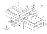
図1において、液晶表示装置1には、四角形状に形成された対象物としての基板2が備えられて、本実施形態では、その基板2の長手方向をX矢印方向とし、X矢印方向と直交する方向をY矢印方向とする。
In FIG. 1, the liquid
基板2の一側面(表面2a)であって、その略中央位置には、液晶分子を封入した四角形状の表示部3が形成されて、その表示部3の外側には、走査線駆動回路4及びデータ線駆動回路5が形成されている。液晶表示装置1は、これら走査線駆動回路4の供給する走査信号と、データ線駆動回路5の供給するデータ信号に基づいて、前記表示部3内の液晶分子の配向状態を制御するようになっている。そして、液晶表示装置1は、図示しない照明装置からの平面光を液晶分子の配向状態によって変調して、表示部3の領域に所望の画像を表示するようになっている。
On one side surface (
基板2の表面2aであって、その左側下隅には、液晶表示装置1の識別コード10が形成されている。識別コード10は、一辺が約1mmの正方形で形成されたコード形成領域S内に形成されている。コード形成領域Sは、16行×16列のデータセルCに仮想分割されて、選択されたデータセルCの領域に、半球状のパターンとしてのドットDが形成されている。
An
本実施形態では、最もX矢印方向側に位置する列のデータセルCを「先端セルC1」とし、最も反X矢印方向側に位置する列のデータセルを「末端セルC16」という。また、ドットDの形成されたデータセルCの中心位置を「目標吐出位置P」とし、各データセルCの一辺の長さを「セル幅W」という。 In the present embodiment, the data cell C in the column located closest to the X arrow direction is referred to as “leading cell C1”, and the data cell located in the most anti-X arrow direction is referred to as “terminal cell C16”. Further, the center position of the data cell C in which the dot D is formed is referred to as “target ejection position P”, and the length of one side of each data cell C is referred to as “cell width W”.
各ドットDは、その外径がデータセルCの一辺の長さ(セル幅W)で形成されたパターンであって、パターン形成材料としての金属微粒子(例えば、ニッケル微粒子やマンガン微粒子)を分散媒に分散させた液状体F(図5参照)の液滴FbをデータセルCに吐出し、データセルCに着弾した液滴Fbを乾燥及び焼成させることによって形成されている。着弾した液滴Fbの乾燥・焼成は、レーザ光B(図6参照)を照射することによって行わ
れる。尚、本実施形態では、液滴Fbを乾燥・焼成することによってドットDを形成するようにしているが、これに限らず、例えばレーザ光Bの乾燥のみによって形成するようにしてもよい。
Each dot D is a pattern in which the outer diameter is formed by the length of one side (cell width W) of the data cell C, and metal fine particles (for example, nickel fine particles and manganese fine particles) as a pattern forming material are dispersed in the dispersion medium. The droplets Fb of the liquid material F (see FIG. 5) dispersed in are discharged to the data cell C, and the droplets Fb landed on the data cell C are dried and fired. The landing droplet Fb is dried and fired by irradiating with laser beam B (see FIG. 6). In this embodiment, the dots D are formed by drying and firing the droplets Fb. However, the present invention is not limited to this, and the droplets may be formed only by drying the laser beam B, for example.
そして、識別コード10は、各データセルC内のドットDの有無によって、液晶表示装置1の製品番号やロット番号等を再現できるようになっている。
次に、前記識別コード10を形成するための液滴吐出装置について説明する。
The
Next, a droplet discharge device for forming the
図2に示すように、液滴吐出装置20には、その長手方向がX矢印方向に沿う直方体形状に形成された基台21が備えられている。基台21の上面には、X矢印方向に延びる1対の案内溝22が形成されるとともに、X軸モータMX(図8参照)に駆動連結される基板ステージ23が、その案内溝22に案内されて所定の速度(搬送速度Vx)でX矢印方向及び反X矢印方向に直動するようになっている。基板ステージ23の上面には、図示しない吸引式のチャック機構が設けられるとともに、載置される基板2が、表面2a(コード形成領域S)を上側にして位置決め固定されるようになっている。
As shown in FIG. 2, the
基台21のY矢印方向両側には、門型に形成された案内部材24が配設されている。案内部材24の上側には、液状体Fを収容する収容タンク25が配設されて、収容する液状体Fを液滴吐出ヘッド(以下単に、「吐出ヘッド」という。)30に導出するようになっている。案内部材24の下側には、Y矢印方向に延びる上下一対の案内レール26がY矢印方向全幅にわたり形成されて、Y軸モータMY(図8参照)に駆動連結されるキャリッジ27が、その案内レール26に沿ってY矢印方向及び反Y矢印方向に直動するようになっている。
On both sides of the base 21 in the Y arrow direction, guide
キャリッジ27の下側には、吐出ヘッド30が搭載されている。図3は、吐出ヘッド30を基板2側から見た斜視図であって、図4〜図7は、それぞれ基板2がX矢印方向に搬送されるときの吐出ヘッド30を説明する概略側断面図である。
A
図3に示すように、吐出ヘッド30の基板2側(反Z矢印方向側)には、ノズルプレート31が備えられている。ノズルプレート31は、ステンレス等の板部材であって、その基板2側の側面(ノズル形成面31a)には、Y矢印方向に沿って等間隔(前記セル幅Wのピッチ幅)に配列された16個のノズルNが形成されている。図4に示すように、各ノズルNは、基板2の法線方向(Z矢印方向)に沿ってノズルプレート31に貫通形成された円形孔である。
As shown in FIG. 3, a
本実施形態では、表面2a上の位置であって、前記各ノズルNの反Z矢印方向に相対する位置を、それぞれ「着弾位置PF」という。
各ノズルNのZ矢印方向には、収容タンク25に連通するキャビティ32が形成されて、収容タンク25の導出する液状体Fを、それぞれ対応するノズルN内に供給するようになっている。各キャビティ32の上側には、Z矢印方向及び反Z矢印方向(上下方向)に振動可能な振動板33が貼り付けられて、キャビティ32内の容積を拡大・縮小するようになっている。振動板33の上側には、各ノズルNに対応する複数の圧電素子PZが配設されて、圧電素子PZを駆動制御するための信号(圧電素子駆動電圧COM1:図8参照)を受けて上下方向に収縮・伸張し、対応する振動板33を上下方向に振動させるようになっている。
In the present embodiment, the positions on the
In the direction of the arrow Z of each nozzle N, a
そして、図5に示すように、基板2をX矢印方向に搬送し、目標吐出位置Pが着弾位置PFに位置するタイミングで、圧電素子PZを収縮・伸張させる。すると、対応するキャビティ32内の容積が拡大・縮小し、ノズルN内の液状体Fの界面(メニスカスK)が振動して、所定容量の液状体Fが、対応するノズルNから液滴Fbとして吐出される。ノズ
ルNから吐出された液滴Fbは、反Z矢印方向に飛行して、対応する着弾位置PF(目標吐出位置P)に着弾する。
Then, as shown in FIG. 5, the
目標吐出位置Pに着弾した液滴Fbは、基板ステージ23の搬送移動とともにX矢印方向に移動し、その搬送時間の経過とともに、対応するデータセルC内で濡れ広がって、乾燥するためのサイズ(本実施形態では、前記セル幅W)まで拡大する。
The droplet Fb that has landed on the target discharge position P moves in the direction of the arrow X along with the transport movement of the
本実施形態では、搬送移動される液滴Fbの中心位置(目標吐出位置P)であって、その液滴Fbの外径がセル幅Wになる位置を、「照射位置PT」という。また、液滴Fbの吐出動作の開始時から、吐出した液滴Fbが照射位置PTに到達するまでの時間を、「照射待機時間T1」という。 In the present embodiment, the center position (target discharge position P) of the droplet Fb to be transported and moved, and the position where the outer diameter of the droplet Fb becomes the cell width W is referred to as “irradiation position PT”. The time from the start of the discharge operation of the droplet Fb until the discharged droplet Fb reaches the irradiation position PT is referred to as “irradiation standby time T1”.
尚、本実施形態の吐出ヘッド30では、ノズルN内のメニスカスKを振動させて前記液滴Fbを吐出させている。そのため、液滴Fbを吐出するときに、メニスカスKの一部が、液滴Fbのサイズよりも小さいサイズの液滴(微小液滴)となって放出される場合がある。こうした微小液滴の殆どは、飛行方向の定まらないミストMとなって、吐出ヘッド30の周辺を浮遊するようになる。
In the
図2に示すように、基台21の反Y矢印方向側であって前記案内部材24の下方には、洗浄手段としてのメンテナンスユニットMUが配設されている。メンテナンスユニットMUには、吐出ヘッド30の各ノズルNから増粘した液状体Fを吸引する図示しない吸引手段や、吐出ヘッド30のノズル形成面31aに付着した液状体Fを払拭する図示しないワイピング手段が配設されている。
As shown in FIG. 2, a maintenance unit MU serving as a cleaning unit is disposed on the side of the base 21 in the direction opposite to the arrow Y and below the
そして、メンテナンスユニットMUは、各ノズルN内の液状体Fの乾燥を回避するために、すなわち各ノズルNの目詰まりを回避するために、増粘した液状体Fを適宜強制的に吸引し、ノズル形成面31aを払拭することによって、吐出ヘッド30を洗浄し、その液滴吐出動作を安定化させている。
The maintenance unit MU forcibly sucks the thickened liquid material F as appropriate in order to avoid drying of the liquid material F in each nozzle N, that is, in order to avoid clogging of each nozzle N, By wiping the
尚、本実施形態のメンテナンスユニットMUでは、各ノズルNの液状体Fを強制的に吸引する、あるいはノズル形成面31aに付着した液状体Fを機械的に払拭するため、吸引された(あるいは払拭された)液状体Fの一部が、メンテナンスユニットMUの近傍、すなわち吐出ヘッド30の近傍で、ミストMとして浮遊するようになる。
In the maintenance unit MU of the present embodiment, the liquid material F of each nozzle N is forcibly sucked or the liquid material F adhering to the
図3に示すように、吐出ヘッド30のX矢印方向側には、キャリッジ27に配設されてレーザ照射手段を構成するレーザヘッド35が備えられている。レーザヘッド35は、箱体状に形成された筐体35aを有し、その筐体35aが、キャリッジ27から基板2側(反Z矢印方向側)に延びる一対の支持部27aに支持固定されている。
As shown in FIG. 3, a
筐体35aの一側面であって基板2側(反Z矢印方向側)の側面(照射面35s)には、16個の照射口36が備えられている。各照射口36は、照射面35sを貫通形成した円形孔であって、それぞれ前記ノズルNのX矢印方向側に形成されるとともに、Y矢印方向に沿ってセル幅Wの等間隔で一列に配列されている。
Sixteen
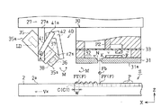
図6に示すように、筐体35aの内部には、各照射口36に対応する半導体レーザLDが配設されるとともに、液状体F(分散媒や金属微粒子)の吸収波長に対応した波長領域のレーザ光Bを出射するようになっている。筐体35aの内部であって各半導体レーザLDの基板2側には、それぞれ半導体レーザLDからのレーザ光Bを平行光束にするコリメータ37が配設されている。各コリメータ37の基板2側には、それぞれ対応するコリメータ37からのレーザ光を表面2a側に収束して液滴Fbを覆うサイズの光断面(ビーム
スポット)を表面2aに形成する集光レンズ38が配設されている。これら半導体レーザLD、コリメータ37及び集光レンズ38からなる光学系は、半導体レーザLDからのレーザ光Bを照射位置PTに導く光軸A1を形成するようになっている。
As shown in FIG. 6, a semiconductor laser LD corresponding to each
そして、レーザ光Bを出射するための駆動信号(レーザ駆動電圧COM2:図8参照)を対応する半導体レーザLDに供給して、所定強度のレーザ光Bを対応する集光レンズ38から出射させる。集光レンズ38から出射されたレーザ光Bは、照射位置PTの領域を照射し、照射位置PTを搬送速度Vxで通過する液滴Fbを、瞬時に乾燥して固化する。固化した液滴Fbは、連続するレーザ光Bの照射によって金属微粒子が焼成されて、外径がセル幅WからなるドットDとして基板2の表面2aに固着する。
Then, a drive signal (laser drive voltage COM2: see FIG. 8) for emitting the laser beam B is supplied to the corresponding semiconductor laser LD, and the laser beam B having a predetermined intensity is emitted from the corresponding
尚、本実施形態の液滴吐出装置20では、着弾した液滴Fbの溶媒あるいは分散媒成分を蒸発させてドットDを形成するようにしている。そのため、液滴Fbにレーザ光Bを照射すると、図6に示すように、液滴Fbからの蒸発成分Eが、吐出ヘッド30及びレーザヘッド35の近傍で浮遊するようになる。この際、レーザヘッド35の近傍に浮遊する前記蒸発成分Eや前記ミストMは、レーザ光Bの領域に侵入すると、レーザ光Bからの光エネルギーを受けて、そのエネルギーの一部をレーザ光Bの進行方向に沿う並進運動エネルギーに変換する。そのため、レーザ光Bの領域に侵入した蒸発成分EやミストMは、直ちにレーザ光Bの領域(光軸A1上)から弾き出されて、照射口36から離間する方向に吹き飛ばされる。
In the
図3に示すように、レーザヘッド35(筐体35a)と吐出ヘッド30との間には、レーザ照射手段を構成する開閉機構40が配設されている。開閉機構40は、前記支持部27aに取着される一対の回動部材41と、前記一対の回動部材41に連結されるキャップ42を有している。
As shown in FIG. 3, an opening /
一対の回動部材41は、それぞれ短冊状に形成されて、一対の支持部27aの先端部に回動可能に取着されている。各回動部材41は、その基端部が回動モータMR(図8参照)に駆動連結されるとともに、その先端部41aが、対応する支持部27aの先端部(回動軸A)を中心にして回動するようになっている。
The pair of rotating
詳述すると、図4及び図5に示すように、各回動部材41は、それぞれの先端部41aを吐出ヘッド30側に向ける位置(以下単に、「閉位置」という。)と、それぞれの先端部41aをキャリッジ27側に向ける位置(以下単に、「開位置」という。)との間を回動するようになっている。
More specifically, as shown in FIGS. 4 and 5, each rotating
そして、回動モータMRを正転駆動すると、各回動部材41は、回動軸Aを中心にして図4に示す状態から左回りに回動し、図5に示す状態、すなわち「開位置」まで移動する。反対に、回動モータMRを逆転駆動すると、各回動部材41は、回動軸Aを中心にして図5に示す状態から右回りに回動し、図4に示す状態、すなわち「閉位置」まで移動する。
When the rotation motor MR is driven to rotate forward, each
キャップ42は、そのY矢印方向の幅が筐体35aと略同じ幅に形成された断面L字型のキャップであるとともに、そのY矢印方向の両側端部が、それぞれ前記一対の回動部材41の先端部41aに連結固定されている。このキャップ42は、可撓性の光吸収性材料で形成されて、半導体レーザLD(集光レンズ38)からのレーザ光Bを吸収するようになっている。
The
キャップ42の一側面であってレーザヘッド35側の側面には、シール面42sが形成されている。シール面42sは、図5に示すように、一対の回動部材41が「開位置」に
位置するときに、照射面35sから離間して照射口36を開放し、図4に示すように、一対の回動部材41が「閉位置」に位置するときに、照射面35sと密着して各照射口36を封止するようになっている。
A
そして、回動モータMRを正転駆動して回動部材41を「開位置」まで回動すると、キャップ42は、回動軸Aを中心にして図4に示す状態から左回りに回動(開動)し、図5に示すように、そのシール面42sを照射面35sから離間させて、照射口36(光軸A1)を開放する。
Then, when the rotation motor MR is driven forward to rotate the
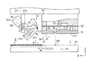
反対に、回動モータMRを逆転駆動して回動部材41を「閉位置」まで回動すると、キャップ42は、回動軸Aを中心にして図5に示す状態から右回りに回動(閉動)し、図4に示すように、シール面42sを照射面35sに密着させて、照射口36を封止する。すなわち、レーザ光Bの光学系(半導体レーザLD、コリメータ37及び集光レンズ38)を外気から遮断する。
On the contrary, when the rotation motor MR is driven in reverse to rotate the
ここで、キャップ42を開動して各照射口36を開放し、各照射口36からレーザ光Bを出射する状態では、図6に示すように、上記する蒸発成分EやミストMが、レーザ光Bの領域(光軸A1上)から弾き出されて、照射口36から離間する方向に吹き飛ばされている。そのため、レーザ光Bを出射する状態から、キャップ42を閉動して照射口36を閉じると、図7に示すように、蒸発成分EやミストMが照射口36の近傍から吹き飛ばされた状態で、レーザ光Bの光学系を外気から遮断することができる。これによって、光学系に対する蒸発成分EやミストMの付着、すなわち光学系の汚染を回避することができる。
Here, when the
尚、この間、レーザ光Bの照射され続けるキャップ42は、照射口36からのレーザ光Bを吸収して終端させる。そのため、キャップ42の閉動によるレーザ光Bの反射・散乱を回避することができ、反射光や散乱光の照射による各種部材(例えば、吐出ヘッド30や基板ステージ23)の損傷を回避することができる。
During this time, the
本実施形態では、回動部材41が、「開位置」から「閉位置」までの回動に要する時間、すなわちキャップ42の閉動によって光学系を外気から遮断するための時間を、「閉動時間T2」という。
In the present embodiment, the time required for the
次に、上記のように構成した液滴吐出装置20の電気的構成を図8に従って説明する。
図8において、開閉制御手段を構成する制御部51は、CPU、RAM、ROM等を備え、ROM等に格納された各種データと各種制御プログラムに従って、基板ステージ23を移動させて、液滴吐出ヘッド30、レーザヘッド35及び開閉機構40を駆動させる。
Next, the electrical configuration of the
In FIG. 8, the
詳述すると、制御部51のROMには、ビットマップデータBMDと閉動用データCBDが格納されている。ビットマップデータBMDは、各ビットの値(0あるいは1)に応じて、圧電素子PZのオンあるいはオフを規定するものであり、二次元描画平面(コード形成領域S)上における各データセルCに、液滴Fbを吐出するか否かを規定するデータである。
More specifically, the ROM of the
閉動用データCBDは、各ビットの値(0あるいは1)に応じて、半導体レーザLDのオンあるいはオフを規定するものであり、16個の半導体レーザLDに、レーザ光Bを出射させるか否かを規定するデータである。尚、本実施形態の閉動用データCBDは、全ての半導体レーザLDを前記「閉動時間T2」の間だけ一斉にオンするように規定されている。 The closing data CBD defines whether the semiconductor laser LD is turned on or off according to the value (0 or 1) of each bit. Whether or not the 16 semiconductor lasers LD emit the laser beam B is determined. It is data that prescribes. Note that the closing data CBD of the present embodiment is defined such that all the semiconductor lasers LD are turned on all at once during the “closing time T2”.
制御部51には、起動スイッチ、停止スイッチ等の操作スイッチを有した入力装置52が接続されて、入力装置52からの各種操作信号や識別コード10の画像が既定形式の描画データIaとして入力されるようになっている。そして、制御部51は、入力装置52からの描画データIaを受けて、前記ビットマップデータBMDと、各圧電素子PZを駆動するための圧電素子駆動電圧COM1と、半導体レーザLDを駆動するためのレーザ駆動電圧COM2を生成する。
An
制御部51には、X軸モータ駆動回路53が接続されて、X軸モータ駆動回路53に対応する駆動制御信号を出力するようになっている。X軸モータ駆動回路53は、制御部51からの駆動制御信号に応答して、基板ステージ23を搬送速度Vxで往復移動させるX軸モータMXを正転又は逆転させるようになっている。
An X-axis
制御部51には、Y軸モータ駆動回路54が接続されて、Y軸モータ駆動回路54に対応する駆動制御信号を出力するようになっている。Y軸モータ駆動回路54は、制御部51からの駆動制御信号に応答して、キャリッジ27を往復移動させるY軸モータMYを正転又は逆転させるようになっている。
A Y-axis
制御部51には、基板2の端縁を検出可能な基板検出装置55が接続されて、基板検出装置55からの検出信号に基づいて、ノズルNの直下(着弾位置PF)を通過する基板2の位置を算出するようになっている。
A
制御部51には、X軸モータ回転検出器56が接続されて、X軸モータ回転検出器56からの検出信号が入力されるようになっている。制御部51は、X軸モータ回転検出器56からの検出信号に基づいて、基板2の移動方向及び移動量を演算するようになっている。
An X-axis
そして、制御部51は、先端セルC1の「目標吐出位置P」が「着弾位置PF」に位置するタイミングで、吐出ヘッド駆動回路58及びレーザ駆動回路59に、それぞれ吐出タイミング信号LP1を出力するようになっている。また、制御部51は、末端セルC16が「照射位置PT」を通過したタイミングで、回動モータ駆動回路60に、閉動タイミング信号LP2を出力するようになっている。
Then, the
制御部51には、Y軸モータ回転検出器57が接続されて、Y軸モータ回転検出器57からの検出信号が入力されるようになっている。制御部51は、Y軸モータ回転検出器57からの検出信号に基づいて、液滴吐出ヘッド30のY矢印方向の移動方向及び移動量を演算するようになっている。そして、制御部51は、各ノズルNに対応する着弾位置PFを、それぞれ目標吐出位置Pの搬送経路上に配置するようになっている。
A Y-axis motor rotation detector 57 is connected to the
制御部51には、吐出ヘッド駆動回路58が接続されて、吐出タイミング信号LP1を出力するようになっている。また、制御部51は、圧電素子駆動電圧COM1を所定の基準クロック信号に同期させて、吐出ヘッド駆動回路58に出力するようになっている。さらにまた、制御部51は、ビットマップデータBMDを所定の基準クロック信号に同期させて吐出制御信号SIPを生成し、その吐出制御信号SIPを、吐出ヘッド駆動回路58にシリアル転送するようになっている。吐出ヘッド駆動回路58は、制御部51からの吐出制御信号SIPを各圧電素子PZに対応させてシリアル/パラレル変換するようになっている。
The
そして、吐出ヘッド駆動回路58は、制御部51からの吐出タイミング信号LP1を受けると、吐出制御信号SIPに基づいて選択された圧電素子PZに、それぞれ圧電素子駆動電圧COM1を供給するようになっている。
When the ejection
制御部51には、レーザ駆動回路59が接続されて、吐出タイミング信号LP1を出力するようになっている。また、制御部51は、レーザ駆動電圧COM2を所定の基準クロック信号に同期させて、レーザ駆動回路59に出力するようになっている。さらにまた、制御部51は、ビットマップデータBMDの後段に閉動用データCBDを付加したデータを所定の基準クロック信号に同期させて照射制御信号SILを生成し、その照射制御信号SILを、レーザ駆動回路59に順次シリアル転送するようになっている。レーザ駆動回路59は、制御部51からの照射制御信号SILを各半導体レーザLDに対応させてシリアル/パラレル変換するようになっている。
A
そして、レーザ駆動回路59は、制御部51からの吐出タイミング信号LP1を受けると、所定の時間(前記「照射待機時間T1」)だけ待機して、照射制御信号SILに対応した各半導体レーザLDに、それぞれレーザ駆動電圧COM2を供給するようになっている。
Upon receiving the ejection timing signal LP1 from the
換言すると、制御部51は、レーザ駆動回路59を介して、着弾した液滴Fbが照射位置PTに搬送移動される都度、液滴Fbに対応する照射口36から、液滴Fbの領域に向かってレーザ光Bを照射するようになっている。
In other words, each time the landed droplet Fb is transported and moved to the irradiation position PT via the
しかも、制御部51は、レーザ駆動回路59を介して、全ての液滴Fbの領域(末端セルC16の液滴Fbの領域)にレーザ光Bを照射すると、全ての半導体レーザLD(照射口36)から、所定の時間(前記閉動時間T2)だけレーザ光Bを出射するようになっている。
In addition, when the
制御部51には、回動モータ駆動回路60が接続されて、吐出タイミング信号LP1及び閉動タイミング信号LP2を出力するようになっている。回動モータ駆動回路60は、制御部51からの吐出タイミング信号LP1及び閉動タイミング信号LP2に応答して、照射口36を開閉させる回動モータMRを正転又は逆転させるようになっている。
A rotation
詳述すると、制御部51は、図4に示すように、先端セルC1の「目標吐出位置P」が「着弾位置PF」に位置するタイミングで、回動モータ駆動回路60に吐出タイミング信号LP1を出力し、回動モータMRを正転させる。そして、制御部51は、キャップ42(シール面42s)の開動を開始して、照射口36を開けた状態で保持する。また、制御部51は、図7に示すように、末端セルC16が「照射位置PT」を通過したタイミングで、回動モータ駆動回路60に閉動タイミング信号LP2を供給し、回動モータMRを逆転させる。そして、制御部51は、キャップ42(シール面42s)の閉動を開始して、照射口36を閉じた状態で保持する。
More specifically, as shown in FIG. 4, the
次に、液滴吐出装置20を使って識別コード10を形成する方法について説明する。
まず、図2に示すように、基板ステージ23上に、表面2aが上側になるように基板2を配置固定する。このとき、基板2のX矢印方向側の辺は、案内部材24(キャリッジ27)より反X矢印方向側に配置されて、キャップ42は、各照射口36を封止している。
Next, a method for forming the
First, as shown in FIG. 2, the
この状態から、入力装置52を操作して描画データIaを制御部51に入力する。すると、制御部51は、描画データIaに基づくビットマップデータBMDを生成して格納し、圧電素子駆動電圧COM1及びレーザ駆動電圧COM2を生成する。
From this state, the
圧電素子駆動電圧COM1及びレーザ駆動電圧COM2を生成すると、制御部51は、Y軸モータMYを駆動制御して、基板2をX矢印方向に搬送するときに、各目標吐出位置Pがそれぞれ対応する着弾位置PFを通過するように、キャリッジ27(各ノズルN)を
セットする。
When the piezoelectric element drive voltage COM1 and the laser drive voltage COM2 are generated, the
キャリッジ27をセットすると、制御部51は、X軸モータMXを駆動制御して、基板2のX矢印方向への搬送を開始し、基板検出装置55及びX軸モータ回転検出器56からの検出信号に基づいて、先端セルC1の目標吐出位置Pが着弾位置PFまで搬送されたか否か判断する。この間、制御部51は、吐出ヘッド駆動回路58に、圧電素子駆動電圧COM1及び吐出制御信号SIPを出力し、レーザ駆動回路59に、レーザ駆動電圧COM2及び照射制御信号SILを出力し、これら吐出ヘッド駆動回路58及びレーザ駆動回路59の双方に、それぞれ吐出タイミング信号LP1を出力するタイミングを待つ。
When the
そして、先端セルC1の目標吐出位置Pが着弾位置PFに搬送されると、制御部51は、回動モータ駆動回路60、吐出ヘッド駆動回路58及びレーザ駆動回路59に、それぞれ吐出タイミング信号LP1を出力する。
When the target discharge position P of the tip cell C1 is conveyed to the landing position PF, the
吐出タイミング信号LP1を回動モータ駆動回路60に出力すると、制御部51は、回動モータ駆動回路60を介して、回動モータMRを正転駆動し、図4に示す矢印方向にキャップ42を開動して各照射口36を開放する。
When the discharge timing signal LP1 is output to the rotation
吐出タイミング信号LP1を吐出ヘッド駆動回路58に出力すると、制御部51は、吐出ヘッド駆動回路58を介して、吐出制御信号SIPに基づいて選択された圧電素子PZに、それぞれ圧電素子駆動電圧COM1を供給し、選択されたノズルNから、一斉に液滴Fbを吐出させる。吐出された液滴Fbは、対応する着弾位置PF(目標吐出位置P)に着弾して、搬送時間の経過とともに濡れ広がる。そして、吐出動作の開始から「照射待機時間T1」だけ経過すると、制御部51は、図5に示すように、先端セルC1の液滴Fbの外径がセル幅Wになるタイミングで、同液滴Fbを照射位置PTに搬送する。
When the ejection timing signal LP1 is output to the ejection
吐出タイミング信号LP1をレーザ駆動回路59に出力すると、制御部51は、レーザ駆動回路59を介して、半導体レーザLDを「照射待機時間T1」だけ待機させ、その後に、吐出制御信号SIPに基づいて選択された半導体レーザLDに、それぞれレーザ駆動電圧COM2を供給する。そして、制御部51は、選択された半導体レーザLDから、一斉にレーザ光Bを出射させる。
When the ejection timing signal LP1 is output to the
半導体レーザLDから出射されたレーザ光Bは、開放された照射口36を介して、照射位置PTに位置する液滴Fbの領域、すなわちセル幅Wからなる液滴Fbの領域に照射される。レーザ光Bの照射された液滴Fbは、分散媒の蒸発と金属微粒子の焼成によって、その外径がセル幅WのドットDとして基板2の表面2aに固着される。これによって、先端セルC1に、セル幅Wに整合したドットDが形成される。
The laser beam B emitted from the semiconductor laser LD is irradiated to the region of the droplet Fb located at the irradiation position PT, that is, the region of the droplet Fb having the cell width W through the opened
以後、同様に、制御部51は、基板2をX矢印方向に搬送して、各目標吐出位置Pが着弾位置PFに到達する毎に、選択したノズルNから液滴Fbを吐出し、着弾した液滴Fbがセル幅Wになるタイミングで、液滴Fbの領域にレーザ光Bを照射する。これによって、コード形成領域S内に、全てのドットDを形成する。
Thereafter, similarly, the
そして、末端セルC16の液滴Fbが「照射位置PT」を通過すると、制御部51は、回動モータ駆動回路60に、閉動タイミング信号LP2を出力する。閉動タイミング信号LP2を出力すると、制御部51は、回動モータ駆動回路60を介して、回動モータMRを逆転駆動し、図7に示すように、キャップ42を閉動して各照射口36を閉じる。
Then, when the droplet Fb of the terminal cell C16 passes through the “irradiation position PT”, the
このとき、制御部51は、レーザ駆動回路59を介して、吐出制御信号SIPに対応した半導体レーザLD、すなわち全ての半導体レーザLDに、それぞれレーザ駆動電圧CO
M2を供給する。すなわち、制御部51は、各照射口36を閉じる間、全ての照射口36からレーザ光Bを出射させて、蒸発成分EやミストMを、照射口36の近傍から吹き飛ばす。
At this time, the
Supply M2. That is, the
従って、レーザ光Bの光学系を、蒸発成分EやミストMのない状態で、外気から遮断することができ、これによって、光学系に対する蒸発成分EやミストMの付着、すなわち光学系の汚染を回避することができる。 Therefore, the optical system of the laser beam B can be shielded from the outside air in the absence of the evaporation component E and mist M, thereby preventing the evaporation component E and mist M from adhering to the optical system, that is, contamination of the optical system. It can be avoided.
そして、末端セルC16の液滴Fbが「照射位置PT」を通過して「閉動時間T2」だけ経過すると、制御部51は、キャップ42の閉動を完了して、レーザ駆動回路59を介して、レーザ光Bの出射を停止する。これによって、光学系の汚染を回避して、識別コード10を形成することができる。
When the droplet Fb of the end cell C16 passes through the “irradiation position PT” and the “closing time T2” has elapsed, the
識別コード10を形成すると、制御部51は、Y軸モータMYを駆動制御して、吐出ヘッド30がメンテナンスユニットMUの直上に位置するように、キャリッジ27(各ノズルN)をセットする。キャリッジ27をセットすると、制御部51は、メンテナンスユニットMUを駆動制御して、各ノズルN内の液状体Fの強制的な吸引と、ノズル形成面31aの払拭を実行し、吐出ヘッド30を洗浄する。
When the
このとき、レーザヘッド35の近傍には、洗浄した液状体Fの一部がミストMとして浮遊するが、照射口36を閉じているために、レーザ光Bの光学系の汚染を回避することができる。
At this time, a part of the cleaned liquid F floats as mist M in the vicinity of the
次に、上記のように構成した本実施形態の効果を以下に記載する。
(1)上記実施形態によれば、レーザヘッド35の搭載されたキャリッジ27に、レーザヘッド35の各照射口36を開閉するキャップ42を有した開閉機構40を設けた。そして、全てのドットDを形成した後に、各半導体レーザLDからのレーザ光Bを各照射口36に出射している状態でキャップ42を閉動し、各照射口36の閉じた状態を保持するようにした。
Next, effects of the present embodiment configured as described above will be described below.
(1) According to the above embodiment, the
従って、各照射口36からのレーザ光Bによって、液滴Fbの吐出動作時に発生するミストMや液滴Fbの乾燥時に発生する蒸発成分Eを、照射口36の近傍から離間させることができ、その状態で、レーザ光Bの光学系を遮断することができる。その結果、光学系に対する蒸発成分EやミストMの付着、すなわち光学系の汚染を回避することができる。そのため、レーザ光Bの光学特性を維持することができ、液滴FbからなるドットDの形状制御性を向上することができる。
Therefore, the laser beam B from each
(2)上記実施形態によれば、キャップ42を光吸収性材料によって構成するようにした。従って、レーザ光Bの照射され続けるキャップ42によって、照射口36からのレーザ光Bを吸収して終端させることができる。その結果、キャップ42の閉動によるレーザ光Bの反射・散乱を回避することができ、反射光や散乱光の照射による各種部材(例えば、吐出ヘッド30や基板ステージ23)の損傷を回避することができる。
(2) According to the embodiment, the
(3)上記実施形態によれば、キャップ42を可撓性部材で構成し、その一側面に、照射面35sと密着して各照射口36を封止するシール面42sを形成した。従って、シール面42sを照射面35s(照射口36)に密着させる分だけ、より確実に光学系の汚染を回避することができる。
(3) According to the above embodiment, the
(4)上記実施形態によれば、レーザヘッド35に複数の照射口36を設け、キャップ42が全ての照射口36を開閉するようにした。そして、全ての照射口36からレーザ光
Bを照射している状態でキャップ42を閉動し、全ての照射口36を閉じるようにした。従って、各照射口36に対応する全ての光学系に対して、蒸発成分EやミストMの付着による汚染を回避することができ、その光学特性を維持することができる。
(4) According to the above embodiment, the
(5)上記実施形態によれば、吐出ヘッド30を洗浄する前に、キャップ42を閉動して、各照射口36を閉じるようにした。従って、吐出ヘッド30を洗浄する場合であっても、洗浄した液状体F(ミストM)による光学系の汚染を回避することができる。
(5) According to the above embodiment, before the
なお、上記実施形態は以下のように変更してもよい。
・上記実施形態では、コード形成領域Sの搬送位置に基づいて、キャップ42を開動及び閉動させる構成にした。これに限らず、例えばレーザ光Bを出射するタイミングや、レーザ光Bの出射を停止するタイミングに基づいて、キャップ42を開動及び閉動させる構成にしてもよく、半導体レーザLDがレーザ光Bを出射している状態で照射口36を閉じる構成であればよい。
・上記実施形態では、液滴Fbの領域に照射するレーザ光Bによって、液滴Fbを乾燥・焼成する構成にした。これに限らず、例えば照射するレーザ光Bのエネルギーによって、液滴Fbを所望の方向に流動させる構成にしてもよく、あるいは液滴Fbの外縁のみに照射して液滴Fbをピニングする構成にしてもよい。すなわち、液滴Fbの領域に照射するレーザ光Bによってパターンを形成する構成であればよい。
・上記実施形態では、レーザ光源を半導体レーザLDで具体化したが、これに限らず、例えば炭酸ガスレーザやYAGレーザであってもよく、着弾した液滴Fbを乾燥可能な波長のレーザ光Bを出力するレーザであればよい。
・上記実施形態では、液滴Fbによって半円球状のドットDを形成する構成にしたが、これに限らず、例えば、楕円形状のドットや線状のパターンを形成する構成であってもよい。
・上記実施形態では、パターンを識別コード10のドットDに具体化した。これに限らず、例えばパターンを、液晶表示装置1や、平面状の電子放出素子を備えて同素子から放出された電子による蛍光物質の発光を利用した電界効果型装置(FEDやSED等)の絶縁膜や金属配線等、各種パターンに具体化してもよく、着弾した液滴Fbの領域にレーザ光を照射して形成するパターンであればよい。
・上記実施形態では、対象物を液晶表示装置1の基板2に具体化したが、これに限らず、例えばシリコン基板やフレキシブル基板、あるいは金属基板等であってもよく、着弾した液滴Fbによってパターンを形成する対象物であればよい。
In addition, you may change the said embodiment as follows.
In the above embodiment, the
In the above embodiment, the droplet Fb is dried and fired by the laser beam B irradiated to the region of the droplet Fb. For example, the configuration may be such that the droplet Fb flows in a desired direction by the energy of the irradiated laser beam B, or the droplet Fb is pinned by irradiating only the outer edge of the droplet Fb. May be. That is, any pattern may be used as long as the pattern is formed by the laser beam B that irradiates the region of the droplet Fb.
In the above embodiment, the laser light source is embodied by the semiconductor laser LD. However, the laser light source is not limited to this. For example, a carbon dioxide laser or a YAG laser may be used. Any laser can be used.
In the above embodiment, the hemispherical dots D are formed by the droplets Fb. However, the present invention is not limited to this. For example, an oval dot or a linear pattern may be formed.
In the above embodiment, the pattern is embodied as the dot D of the
In the above embodiment, the object is embodied in the
2…対象物としての基板、20…液滴吐出装置、30…液滴吐出ヘッド、35…レーザ照射手段を構成するレーザヘッド、36…照射口、40…開閉機構、42…キャップ、51…開閉制御手段を構成する制御部、B…レーザ光、D…パターンとしてのドット、F…液状体、Fb…液滴、LD…レーザ光源としての半導体レーザ、MU…洗浄手段としてのメンテナンスユニット。
DESCRIPTION OF
Claims (7)
前記レーザ光源が前記照射口への前記レーザ光を出射している状態で前記照射口を閉じるようにしたことを特徴とするパターン形成方法。 A droplet containing a pattern forming material is ejected from a droplet ejection head toward an object, and a pattern is formed by irradiating the region of the droplet that has landed on the object with laser light from a laser light source through an irradiation port. In the method of forming a pattern,
The pattern forming method characterized in that the irradiation port is closed in a state where the laser light source emits the laser beam to the irradiation port.
前記液滴吐出ヘッドの液状体を吸引して前記液滴吐出ヘッドを洗浄する前に、前記照射口を閉じるようにしたことを特徴とするパターン形成方法。 In the pattern formation method of Claim 1,
A pattern forming method, wherein the irradiation port is closed before the liquid material of the droplet discharge head is sucked to clean the droplet discharge head.
前記レーザ照射手段は、
前記照射口を開閉する開閉機構と、
前記レーザ光源が前記照射口への前記レーザ光を出射している状態で、前記開閉機構を駆動制御して前記照射口を閉じる開閉制御手段と、
を備えたことを特徴とする液滴吐出装置。 A liquid droplet ejection device comprising: a liquid droplet ejection head that ejects liquid droplets on an object; and a laser irradiation unit that irradiates a laser beam from a laser light source to an area of the liquid droplets that has landed on the object. In the device
The laser irradiation means includes
An opening and closing mechanism for opening and closing the irradiation port;
In a state where the laser light source emits the laser light to the irradiation port, opening / closing control means for driving and controlling the opening / closing mechanism to close the irradiation port;
A droplet discharge apparatus comprising:
前記開閉機構は、前記照射口を閉じて前記照射口からの前記レーザ光を吸収する光吸収性のキャップを備えたことを特徴とする液滴吐出装置。 In the droplet discharge device according to claim 3,
The droplet discharge device, wherein the opening / closing mechanism includes a light-absorbing cap that closes the irradiation port and absorbs the laser light from the irradiation port.
前記開閉機構は、前記照射口に密着して前記照射口を閉じるキャップを備えたことを特徴とする液滴吐出装置。 In the droplet discharge device according to claim 3 or 4,
The droplet ejection device, wherein the opening / closing mechanism includes a cap that is in close contact with the irradiation port and closes the irradiation port.
前記レーザ照射手段は、複数の前記照射口を備え、
前記開閉機構は、前記複数の照射口を開閉し、
前記開閉制御手段は、前記レーザ光源が前記複数の照射口に前記レーザ光を出射している状態で、前記開閉機構を駆動制御して前記複数の照射口を閉じることを特徴とする液滴吐出装置。 In the liquid droplet ejection device according to any one of claims 3 to 5,
The laser irradiation means includes a plurality of the irradiation ports,
The opening / closing mechanism opens and closes the plurality of irradiation ports,
The opening / closing control means drives and controls the opening / closing mechanism to close the plurality of irradiation ports in a state where the laser light source emits the laser light to the plurality of irradiation ports. apparatus.
前記液滴吐出ヘッドの液状体を吸引して前記液滴吐出ヘッドを洗浄する洗浄手段を備え、
前記開閉制御手段は、前記洗浄手段が前記液滴吐出ヘッドを洗浄する前に、前記開閉機構を駆動して前記照射口を閉じることを特徴とする液滴吐出装置。 In the droplet discharge device according to any one of claims 3 to 6,
A cleaning means for cleaning the droplet discharge head by sucking the liquid material of the droplet discharge head;
The opening / closing control unit drives the opening / closing mechanism to close the irradiation port before the cleaning unit cleans the droplet discharge head.
Priority Applications (1)
| Application Number | Priority Date | Filing Date | Title |
|---|---|---|---|
| JP2005300175A JP2007108497A (en) | 2005-10-14 | 2005-10-14 | Pattern forming method and liquid drop discharging device |
Applications Claiming Priority (1)
| Application Number | Priority Date | Filing Date | Title |
|---|---|---|---|
| JP2005300175A JP2007108497A (en) | 2005-10-14 | 2005-10-14 | Pattern forming method and liquid drop discharging device |
Publications (1)
| Publication Number | Publication Date |
|---|---|
| JP2007108497A true JP2007108497A (en) | 2007-04-26 |
Family
ID=38034392
Family Applications (1)
| Application Number | Title | Priority Date | Filing Date |
|---|---|---|---|
| JP2005300175A Pending JP2007108497A (en) | 2005-10-14 | 2005-10-14 | Pattern forming method and liquid drop discharging device |
Country Status (1)
| Country | Link |
|---|---|
| JP (1) | JP2007108497A (en) |
Cited By (1)
| Publication number | Priority date | Publication date | Assignee | Title |
|---|---|---|---|---|
| US20120212553A1 (en) * | 2011-02-21 | 2012-08-23 | Seiko Epson Corporation | Liquid droplet discharging device |
-
2005
- 2005-10-14 JP JP2005300175A patent/JP2007108497A/en active Pending
Cited By (3)
| Publication number | Priority date | Publication date | Assignee | Title |
|---|---|---|---|---|
| US20120212553A1 (en) * | 2011-02-21 | 2012-08-23 | Seiko Epson Corporation | Liquid droplet discharging device |
| CN102673129A (en) * | 2011-02-21 | 2012-09-19 | 精工爱普生株式会社 | Liquid droplet discharging device |
| US8820912B2 (en) * | 2011-02-21 | 2014-09-02 | Seiko Epson Corporation | Liquid droplet discharging device |
Similar Documents
| Publication | Publication Date | Title |
|---|---|---|
| JP4363435B2 (en) | Pattern forming method and droplet discharge apparatus | |
| KR100824610B1 (en) | Droplet ejection apparatus | |
| JP2007289837A (en) | Liquid droplet discharge device and identification code | |
| JP2007160926A (en) | Liquid droplet ejection apparatus | |
| KR100765402B1 (en) | Method for forming a pattern and liquid ejection apparatus | |
| KR100759307B1 (en) | Liquid ejection apparatus | |
| JP4297066B2 (en) | Droplet discharge device and droplet discharge head | |
| JP4400541B2 (en) | Pattern forming method and droplet discharge apparatus | |
| JP4525559B2 (en) | Droplet discharge device | |
| JP2007117922A (en) | Pattern formation method and liquid droplet discharge apparatus | |
| KR100778040B1 (en) | Method for forming mark and liquid ejection apparatus | |
| JP2007108497A (en) | Pattern forming method and liquid drop discharging device | |
| JP2007105661A (en) | Pattern formation method and liquid droplet discharge apparatus | |
| JP4400542B2 (en) | Pattern forming method and droplet discharge apparatus | |
| JP4400540B2 (en) | Pattern forming method and droplet discharge apparatus | |
| JP2007152250A (en) | Pattern forming method and liquid droplet ejection device | |
| JP2007136303A (en) | Liquid drop delivery apparatus | |
| JP4534809B2 (en) | Droplet discharge device | |
| JP2006263560A (en) | Droplet discharge method and droplet discharge apparatus | |
| JP2007144348A (en) | Liquid drop discharge apparatus | |
| JP2007098281A (en) | Pattern formation method and liquid drop delivery apparatus |