JP4399939B2 - Biological information measuring device - Google Patents
Biological information measuring device Download PDFInfo
- Publication number
- JP4399939B2 JP4399939B2 JP2000005883A JP2000005883A JP4399939B2 JP 4399939 B2 JP4399939 B2 JP 4399939B2 JP 2000005883 A JP2000005883 A JP 2000005883A JP 2000005883 A JP2000005883 A JP 2000005883A JP 4399939 B2 JP4399939 B2 JP 4399939B2
- Authority
- JP
- Japan
- Prior art keywords
- subject
- biological information
- state
- predetermined
- measurement control
- Prior art date
- Legal status (The legal status is an assumption and is not a legal conclusion. Google has not performed a legal analysis and makes no representation as to the accuracy of the status listed.)
- Expired - Fee Related
Links
Images


Landscapes
- Measuring And Recording Apparatus For Diagnosis (AREA)
Description
【0001】
【発明の属する技術分野】
本発明は、被験者の呼吸機能、血圧、心電図、脈拍数、酸素飽和度などの生体情報を測定する生体情報測定装置に関するものである。
【0002】
【従来の技術】
一般に、睡眠中に比較的長い無呼吸状態が頻繁に生じる睡眠時無呼吸症候群になると、動脈血中の酸素濃度が著しく低下したり心拍異常を併発することが知られている。また、睡眠中における無呼吸状態は、睡眠を浅くする原因になり、昼間における傾眠状態を引き起こすこともある。このような睡眠時無呼吸症候群の検査は、従来、睡眠ポリソモノグラフィを用いて、睡眠中における無呼吸回数などの無呼吸状態、脳波、眼球運動や酸素飽和度などを測定することにより行われていたが、多数の検査を行うため、被験者を入院させる必要があり、被験者にとって費用的にも時間的にも負担となっていた。また、病院施設という日常と異なる睡眠環境で検査を行うため、普段の睡眠が得られない場合が多く、信頼性のある睡眠結果を得るのが困難であるという問題があった。そこで、被験者を入院させることなく簡易的に睡眠時の無呼吸状態を検査可能な呼吸機能測定装置が提案されている(特開平5−200031号公報)。
【0003】
上記従来の呼吸機能測定装置は、酸素飽和度検出部、呼吸音検出部、体位検出部や心拍数検出用の複数の電極などの被験者に取り付けるための種々の生体情報検出手段を備えるとともに、これらの検出手段からの検出信号を記憶するための測定処理手段を備えている。そして、被験者は、この呼吸機能測定装置を自宅に持ち帰って就寝前に自ら装着し、睡眠中の各検出手段からの検出信号をそのまま、あるいはデータ処理して各種の呼吸機能の測定結果として測定処理手段に記録し、後日、医者などの専門家がこの記録データに基づき解析することで睡眠時無呼吸症候群などの診断を行うようにしている。
【0004】
【発明が解決しようとする課題】
ところが、上記従来の呼吸機能測定装置では、被験者が自ら複数の検出手段を装着した後に電源スイッチをオンにしなければならず、電源スイッチをオンにする操作を忘れると測定が行われないという問題があった。
【0005】
また、電源スイッチをオンにした後で直ぐに就寝しない場合や、翌朝に各検出手段を取り外す際に電源スイッチをオフにする操作を忘れてしまうと、無駄に電力を消費してしまい、測定に使用可能なメモリ容量が低減したり、電源として電池を用いている場合には残容量が低下してしまうという問題があった。
【0006】
本発明は、上記問題を解決するもので、測定すべき状態か否かを判定し、その判定結果に基づき自動的に測定動作を行うことが可能な生体情報測定装置を提供することを目的とする。
【0007】
【課題を解決するための手段】
請求項1の発明は、被験者に取り付けられ、当該被験者の生体に関する情報を検出する少なくとも1つの生体情報検出手段と、所定の測定制御を行う測定制御手段とを備えた生体情報測定装置において、装置が所定の状態か否かを判定する状態判定手段と、上記生体情報検出手段の1つである、上記被験者の体位を検出する体位検出手段とを備え、上記体位検出手段が、上記被験者が横たわっていることを検出すると、上記状態判定手段は、上記所定の状態であると判定し、上記測定制御手段は、上記状態判定手段により上記所定の状態であると判定されている場合のみ、上記所定の測定制御を行うことを特徴としている。
【0014】
この構成によれば、体位検出手段により被験者が横になっていることが検出されると所定の状態と判定されることにより、被験者が立っている状態では測定動作が行われず、必要な測定動作のみが行われることとなり、無駄な電力消費が抑制される。
【0015】
また、請求項2の発明は、請求項1記載の生体情報測定装置において、上記所定の測定制御は、上記体位検出手段以外の上記生体情報検出手段による検出動作を行わせるものであることを特徴としている。
【0016】
また、請求項3の発明は、請求項2記載の生体情報測定装置において、上記所定の測定制御は、上記検出動作を開始させた後に、所定の時間の経過後に上記検出動作を終了するものであることを特徴としている。
【0017】
また、請求項4の発明は、請求項1記載の生体情報測定装置において、測定データを記憶する記憶部を備え、上記記憶部は、上記所定の測定制御により測定された測定データを記憶することを特徴としている。
【0018】
また、請求項5の発明は、被験者に取り付けられ、当該被験者の生体に関する情報を検出する少なくとも1つの生体情報検出手段と、所定の測定制御を行う測定制御手段とを備えた生体情報測定装置において、上記所定の測定制御の開始時点を選択する選択制御手段と、装置が所定の状態か否かを判定する状態判定手段と、上記生体情報検出手段の1つである、上記被験者の体位を検出する体位検出手段とを備え、上記選択制御手段により、上記体位検出手段の検出結果に応じて、所定の測定制御を行うよう、上記開始時点が選択されている場合は、上記体位検出手段が、上記被験者が横たわっていることを検出すると、上記状態判定手段は、上記所定の状態であると判定し、上記測定制御手段は、上記状態判定手段により上記所定の状態であると判定されている場合のみ、上記所定の測定制御を行うことを特徴としている。
【0019】
また、請求項6の発明は、被験者に取り付けられ、当該被験者の生体に関する情報を検出する少なくとも1つの生体情報検出手段と、所定の測定制御を行う測定制御手段とを備えた生体情報測定装置において、電源入力手段と、測定データを記憶する記憶部と、上記生体情報検出手段の1つである、上記被験者の体位を検出する体位検出手段とを備え、上記電源入力手段により電源が入力されることで、上記測定制御手段が上記所定の測定制御を開始した後に、上記体位検出手段が、上記被験者が横たわっていることを検出した場合のみ、前記記憶部は上記所定の測定制御により測定された測定データを記憶することを特徴としている。
【0023】
【発明の実施の形態】
図1は本発明に係る生体情報測定装置の一実施形態である呼吸機能測定装置を被験者に装着した状態を示す図である。
【0024】
この呼吸機能測定装置1は、被験者Pの睡眠時無呼吸状態などの呼吸機能を測定して呼吸の異常を報知するためのもので、酸素飽和度検出部2と、音検出部3と、呼吸検出部4と、呼吸努力検出部5と、中継部6と、体位検出部7(図4)と、測定処理部8とを備えている。
【0025】
酸素飽和度検出部2と測定処理部8とは、接続ケーブル11により接続され、音検出部3、呼吸検出部4および呼吸努力検出部5と中継部6とは、それぞれ、接続ケーブル12,13,14により接続され、中継部6と測定処理部8とは、接続ケーブル12,13,14を1本にまとめた中継ケーブル15により接続されている。
【0026】
接続ケーブル11〜14の先端にはプラグ11a〜14aが取り付けられており、それぞれ、測定処理部8のジャック8a(図10)および中継部6のジャック6a,6b,6c(図10)に取り外し可能に接続されている。また、中継ケーブル15の先端にはプラグ15aが取り付けられており、測定処理部8のジャック8b(図10)に取り外し可能に接続されている。プラグ11a,12a,13a,14a,15aおよびジャック6a,6b,6c,8a,8bは、それぞれコネクタを構成し、取り外し可能に電気的に接続する接続手段としての機能を有する。
【0027】
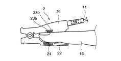
次に、図2〜図9を参照して各部の構成について説明する。図2は酸素飽和度検出部の構成を示す図である。
【0028】
酸素飽和度検出部2は、指先の動脈中の酸素飽和度を検出するもので、図2に示すように、上下のクリップ板21,22の一端部が軸支されて連結され、ばね(図示省略)によって他端部が挾持方向に付勢されたもので、クリップ板21,22により被験者の指16を挾むようにして指先に装着可能になっている。上側のクリップ板21には、吸収率が血中の酸素濃度に依存する波長の光(例えば赤色光)を発するLED23aと、吸収率が血中の酸素濃度にほとんど依存しない波長の光(例えば赤外光)を発するLED23bとが配設され、下側のクリップ板22のLED23a,23bに対向する位置には、LED23a,23bからの発光光のうちで指16を透過した光を受光するフォトダイオード24が配設されており、受光した光強度に応じた受光信号が接続ケーブル11を介して測定処理部8に送られる。
【0029】
図1に戻り、音検出部3は、例えば粘着テープなどによって被験者Pの喉近傍に接着され、被験者Pの気管音やいびき音を検出するマイクロフォンからなるもので、音の大きさに応じた音信号が接続ケーブル12および中継ケーブル15を介して測定処理部8に送られる。
【0030】
呼吸検出部4は、被験者Pの呼吸によって生じる気流を検出するもので、図3に示すように、左鼻息検出部41、右鼻息検出部42および口息検出部43を備え、左鼻息検出部41および右鼻息検出部42がそれぞれ鼻孔の入口に対向するように、かつ口息検出部43が口に対向するように、例えば粘着テープによって被験者Pの鼻の下に接着されている(図1参照)。
【0031】
この呼吸検出部4の左鼻息検出部41、右鼻息検出部42および口息検出部43はそれぞれ例えばサーミスタからなり、図3に示すように、ハウジング44内で導電ライン45,46,47,48により直列に接続されており、この導電ライン45,48が互いに絶縁された状態で接続ケーブル13として1本にまとめられている。
【0032】
左鼻息検出部41、右鼻息検出部42および口息検出部43のいずれかに鼻または口の呼吸による気流が当たると当該検出部の温度が上昇し、導電ライン45,48間の抵抗値の変化となって表われる。従って、呼吸検出部4では、この抵抗値の変化が導電ライン45,48間の電位差の変化として検出されるようになっている。
【0033】
呼吸努力検出部5は、被験者Pの胸部または腹部に装着され、被験者Pの呼吸努力による胸部または腹部の周囲長の変化量を検出するものである。この呼吸努力検出部5は、被験者Pの胸部または腹部に非伸縮性のベルト部材を両端部が重なり合うように巻き付け、被験者Pの呼吸努力による胸部または腹部の周囲長の変化に基づく上記両端部の重なり合う部分の寸法の変化量を検出するもので、ベルト部材を非伸縮性とすることで、上記周囲長の変化が上記重なり合う部分の寸法の変化量に直接的に表れるようにしている。
【0034】
図4は呼吸努力検出部5の検出ボックスの内部構成を示す図である。呼吸努力検出部5は、図1に示すように、検出ボックス51およびベルト52,53を備え、本実施形態では被験者Pの胸部に装着されており、図4に示すように、検出ボックス51内には、移動板55、ばね56、フォトインタラプタ57、ガイド板58a,58b、体位検出部7(後述)などが配設されている。
【0035】
ベルト52,53は伸縮性のないものが採用され、これによって胸部の周囲長の変化が検出ボックス51内の移動板55の移動に正確に反映されるようになっている。ベルト52の一端は、移動板55の左端部55bに固定されている。ばね56の基端56aは、検出ボックス51の所定部51bに固定され、ばね56の先端56bは、移動板55の右端部55aに固定されている。また、ベルト53の一端は、検出ボックス51の右端に設けられた取付部51aに固定されている。
【0036】
ベルト52,53の他端は、図1に示すように、面ファスナ59により、着脱自在、かつ装着位置が調整可能に互いに固定されている。そして、面ファスナ59の装着位置を調整して被験者Pに対する巻付け長さを調整することによって、被験者Pの胸部に呼吸努力検出部5をばね56の適正な弾性力で密着できるようになっている。
【0037】
図4において、移動板55には目盛部61が設けられている。この目盛部61は、図5(a)に示すように、透明なフィルム62にベルトの長手方向(図中、横方向)に所定寸法(本実施形態では例えば0.03mm)のライン63が等間隔(本実施形態では例えば0.06mm)で多数印刷されて構成されている。そして、図5(b)に示すように、フォトインタラプタ57を構成する発光素子(例えばLED)64および受光素子(例えばフォトダイオード)65は、この目盛部61を挾むように配設されている。
【0038】
また、図4において、ガイド板58a,58bは、検出ボックス51に固定され、ベルト52が矢印Q方向に引っ張られたときに移動板55の移動方向を規制するもので、図5(b)にはガイド板58bのみを示しているが、それぞれ、移動板55を挟むように断面コ字状に形成されている。
【0039】
ばね56は弾性手段を構成し、ベルト52,53、移動板55および検出ボックス51は非伸縮性のベルト部材を構成し、ライン63は所定の特性を有する領域を構成し、フォトインタラプタ57は読取部を構成する。また、ライン63は遮断領域を構成し、各ライン63の間のフィルム62の部分は透過領域を構成する。
【0040】
なお、図1に示すように、本実施形態では、呼吸努力検出部5を被験者Pの胸部に装着しているが、腹部に装着するようにしてもよい。また、ばね56に代えて、ゴムなどの弾性手段を用いてもよい。
【0041】
また、図4に示すように、本実施形態では目盛部61を移動板55に設け、フォトインタラプタ57を検出ボックス51に固定しているが、これに限られず、目盛部61を検出ボックス51に設け、フォトインタラプタ57を移動板55に取り付けるようにしてもよい。すなわち、ベルト部材の一方端を構成する移動板55の右端部55aと、ベルト部材の他方端を構成する検出部ボックス51の左端部51cとの相対的な移動量が検出可能であればよい。
【0042】
図1に戻り、中継部6は、音検出部3、呼吸検出部4および呼吸努力検出部5と測定処理部8とを接続する3本の接続ケーブルがもつれて配線が輻輳するのを防止するもので、箱形状でベルト53に固定されている。中継部6の一方の側面には音検出部3、呼吸検出部4および呼吸努力検出部5との接続ケーブル12,13,14の先端のプラグ12a,13a,14aが取り付けられるジャック6a,6b,6c(図10)が設けられ、この反対側の側面には測定処理部8に接続される中継ケーブル15が固定されており、中継部6内では3本の接続ケーブル12,13,14内の信号線が互いに絶縁された状態で1本の中継ケーブル15で出力されるようにまとめられている。
【0043】
体位検出部7は、被験者Pの姿勢(立位、仰臥位、右側臥位、左側臥位、伏臥位等)を検出するものである。
【0044】
この体位検出部7は、複数の接点が設けられた容器内に密閉された導電性の可動体を備えてなる回転位置センサを有するもので、この可動体は、自由に移動可能で、隣接する2接点を短絡する短絡状態を備えている。そして、被験者Pの姿勢変化により可動体が移動すると別の2接点を短絡することになるが、この可動体は、1つの短絡状態と別の短絡状態との間に、いずれの2接点も短絡しない不感状態を備えている。この不感状態は、1つの短絡状態から別の短絡状態に移るときに、1つの接点のみに接触した状態が存在することによって生じるものであるが、これは可動体がいずれの接点にも接触しない開放状態と区別できない。
【0045】
そこで、本実施形態の体位検出部7は、上記のような回転位置センサを2個備えており、双方の回転位置センサが同時に不感状態になることがないような位置関係を有した状態で、被験者Pに取り付けられている。
【0046】
図6は体位検出部の構成を示す図で、(a)は外観の斜視図、(b)は回転位置センサの横断面図、(c)は(b)のC−C線断面図である。図7(a)(b)は被験者が仰臥位であるときの体位検出部の配置状態を示す図、図8は回転位置センサの回転位置に対する接点の短絡状態を示す図、図9は体位検出部の検出回路を示す回路図である。
【0047】
図6(a)において、体位検出部7は、同一構造の回転位置センサ71a,71bと、検出回路72とを備え、それぞれ回路基板73上に配設されており、図4に示すように、呼吸努力検出部5の検出ボックス51に収容されている。このように、体位検出部7を検出ボックス51に収容するようにしたので、体位検出部7を収容するためのボックスを別途備える必要がなくなり、これによって、この呼吸機能測定装置1の装着作業を簡易にするとともに、この装着による被験者Pの違和感を低減することができる。
【0048】
図6(b)、(c)に示すように、回転位置センサ71a,71bは、絶縁部材からなる中空のハウジング(容器)75内に、表面が導電部材からなる可動体76が移動自在に配設されてなる。ハウジング75は、外観の平面視がほぼ正方形の直方体形状で、その天板75aおよび底板75bの中央には、それぞれ球面の凹部75c,75dが形成されている。また、その側板75eの4隅であって高さ方向のほぼ中央位置に、板状の導体からなる接点77a,77b,77c,77dが中心軸71pに向けて突設され、側板75eの互いに対向する面の外部には、これらの接点77a,77b,77c,77dとそれぞれ導通する端子78a,78b,78c,78dが突設されている。
【0049】
図6(b)に示すように、接点77a,77b,77c,77dは、隣接する接点との距離dは、可動体76の直径Rより多少短い距離に設定されており、可動体76を臨む部分は中心軸71pを中心とする円形状に滑らかに形成されている。また、図6(a)、図7に示すように、回転位置センサ71a,71bは、互いに所定角度(本実施形態では、例えば45°)だけ中心軸71p(図6(b))周りに回転した状態(位相が異なる状態)で回路基板73に配設されており、この回路基板73が、図4に示すように、検出ボックス51に図中下向きに固定されている。
【0050】
ここで、図6(b)、図7(a)に示すように、回転位置センサ71aの接点77a,77d間を接点部S1、接点77a,77b間を接点部S2、接点77b,77c間を接点部S3、接点77c,77d間を接点部S4と称し、回転位置センサ71bの接点77a,77d間を接点部T1、接点77a,77b間を接点部T2、接点77b,77c間を接点部T3、接点77c,77d間を接点部T4と称する。
【0051】
この構成によれば、被験者Pが立位(立っている状態)のときは、可動体76が凹部75cに嵌り込んだ状態になるので、可動体76はいずれの接点77a,77b,77c,77dにも接触せず、いずれの2接点間も開放状態(オフ)になる。
【0052】
これに対して、図7(b)に示すように被験者Pが仰臥位の場合には、体位検出部7は、図7(a)において紙面上方が上側(天井側)になり、紙面下方が下側(床側)になるように配置されることになるので、一方の回転位置センサ71aの可動体76は、接点77a,77dの間に嵌り込んだ状態になることから両接点77a,77d間、すなわち接点部S1が短絡(オン)され、他方の回転位置センサ71bの可動体76は、接点77aの先端側の円形部に嵌り込んだ状態になることからいずれの2接点間も開放された不感状態(オフ)になる。
【0053】
次に、図8を用いて、被験者の体位が変化したときの回転位置センサ71a,71bの各接点部の状態について説明する。上記図7で説明したように、被験者Pが仰臥位のときは、回転位置センサ71aの可動体76が接点77a,77dの間に嵌り込んだ状態になることから接点部S1が短絡(オン)する。図7の状態から被験者Pが図中、時計回りに回転すると、一旦可動体76が接点77aの先端側の円形部に嵌り込んだ状態になり、いずれの接点間も開放(オフ)された不感状態A1になる。さらに被験者が回転すると、回転位置センサ71aの可動体76が接点77a,77bの間に嵌り込んだ状態になり、接点部S2が短絡(オン)する。
【0054】
さらに被験者が時計回りに回転すると、回転位置センサ71aは、可動体76が接点77bの先端部に嵌り込んだ不感状態A2→接点部S3がオン→可動体76が接点77cの先端部に嵌り込んだ不感状態A3→接点部S4がオン→可動体76が接点77dの先端部に嵌り込んだ不感状態A4と変化し、被験者が仰臥位に戻ると接点部S1がオンになる。
【0055】
このように、図8の範囲▲1▼は仰臥位に対応し、範囲▲2▼は左側臥位に対応し、範囲▲3▼は伏臥位に対応し、範囲▲4▼は右側臥位に対応する。そして、接点部S1,S2,S3,S4のオンが各体位に対応するが、各接点部のオンから次の接点部のオンに移るまでの間には、いずれの接点部もオンしない不感状態A1,A2,A3,A4が存在する。従って、この回転位置センサ71aだけでは、不感状態A1,A2,A3,A4のときは、被験者Pが立位のときの開放状態と区別することができない。
【0056】
一方、回転位置センサ71bは、図6(a)、図7(a)に示すように、回転位置センサ71aに対して、所定角度(本実施形態では、例えば45°)だけ反時計回りに回転した状態で回路基板73に配設されている。従って、図7において被験者Pが時計回りに回転すると、接点部T1〜T4のオンは、図8に示すように、接点部S1〜S4のオンに対してそれぞれ1/8周期だけ遅れる。これによって、回転位置センサ71aが不感状態A1,A2,A3,A4のときは、それぞれ回転位置センサ71bの接点部T1,T2,T3,T4がオンになる。
【0057】
なお、本実施形態では、回転位置センサ71bは、回転位置センサ71aに対して45°だけ反時計回りに回転した状態で回路基板73に配設しているが、これに限られず、回転位置センサ71aが不感状態A1,A2,A3,A4のときに回転位置センサ71bの接点部T1〜T4のいずれかがオンになるように、すなわち回転位置センサ71a,71bの双方が同時に不感状態とならないように配置しておけばよい。例えば、45°に比べて角度が多少増減してもよく、また、−45°や135°などの角度だけ回転した状態で配置してもよい。
【0058】
次に、図9の回路図を用いて、回転位置センサ71a,71bに接続される検出回路72について説明する。図9において、電源電圧をVCC、抵抗R1〜R5の抵抗値をR1〜R5とする。
【0059】
回転位置センサ71aの端子78aは抵抗R1を介して電源ラインU3に接続され、端子78bは抵抗R3,R4からなる直列回路を介してアースラインU4に接続され、端子78cは電源ラインU3に直接接続され、端子78dは抵抗R2を介して抵抗R3,R4の接続点に接続され、この抵抗R3,R4の接続点が出力ラインU1に接続されている。これによって出力ラインU1に所定レベルの電圧を出力する第1検出回路72aが構成される。
【0060】
一方、回転位置センサ71bの端子78a,78cは、それぞれ電源ラインU3に直接接続され、端子78b,78dは、それぞれ、出力ラインU2に直接接続されるとともに、抵抗R5を介してアースラインU4に接続されている。これによって出力ラインU2に所定レベルの電圧を出力する第2検出回路72bが構成される。
【0061】
図4に示す回路基板73から延びる接続ケーブル73aは、出力ラインU1,U2、電源ラインU3およびアースラインU4の4本の導電ラインが互いに絶縁されて構成されている。
【0062】
このような検出回路72の回路構成により、回転位置センサ71aの接点部S1〜S4がオンのときに出力ラインU1に出力される電圧V1〜V4は、それぞれ、
V1=VCC・R4/(R1+R2+R4) …(1)
V2=VCC・R4/(R1+R3+R4) …(2)
V3=VCC・R4/(R3+R4) …(3)
V4=VCC・R4/(R2+R4) …(4)
となり、全接点部S1〜S4がオフのときに出力ラインU1に出力される電圧V5は、V5=0となる。
【0063】
一方、回転位置センサ71bの接点部T1〜T4のいずれかがオンのときに出力ラインU2に出力される電圧V6は、V6=VCCとなり、回転位置センサ71bの接点部T1〜T4のいずれもがオフのときに出力ラインU2に出力される電圧V7は、V7=0となる。
【0064】
例えばVCC=5(V),R1=100(kΩ),R2=200(kΩ),R3=51(kΩ),R4=100(kΩ),R5=100(kΩ)のときには、V1=1.2(V),V2=2.0(V),V3=3.3(V),V4=1.7(V),V6=5(V)となる。
【0065】
このように、第1検出回路72aの抵抗R1〜R4の抵抗値を適切な値に設定することにより、接点部S1〜S4のオンに対してそれぞれ異なるレベルの電圧を出力ラインU1に出力することができ、これによって回転位置センサ71aの接点部S1〜S4のいずれがオンになっているか、または全ての接点部S1〜S4がオフになっているかを判別することが可能になる。また、第2検出回路72bにより、回転位置センサ71bの接点部T1〜T4のうちでいずれかの接点部がオンになっているか、または全ての接点部T1〜T4がオフになっているかを判別することが可能になる。
【0066】
従って、1個の回転位置センサ71aだけでは、全ての接点部S1〜S4がオフのときに被験者の体位が立位であるのか、または横たわった状態で、かつ不感状態であるのかが判別できない。これに対して、本実施形態の構成によれば、回転位置センサ71aの全ての接点部S1〜S4がオフであっても、回転位置センサ71bの接点部T1〜T4のうちでいずれかの接点部がオンになっていれば被験者の体位が横たわった状態で、かつ不感状態であると判別し、全ての接点部T1〜T4がオフになっていれば被験者の体位が立位であると判別することができる。
【0067】
これによって、被験者の体位が仰臥位、左側臥位、右側臥位、伏臥位および立位のいずれであるかを確実に判別することができる。
【0068】
また、検出回路72を図9に示す回路構成とすることにより、4本の導電ラインU1〜U4で判別することができ、体位検出部7から測定処理部8までの信号ラインの本数を最小限とすることができる。また、回転位置センサ71bは、いずれかの接点部がオンになっているか、またはいずれもオフであるかのみが判別できればよいので、第2検出回路72bを簡素な回路構成にできる。
【0069】
なお、第2検出回路72bも、第1検出回路72aと同様の回路構成としてもよい。これによって、被験者が横たわった状態で回転位置センサ71aが不感状態のときに、回転位置センサ71bのオンになっている接点部を判別できることから、被験者がどの体位とどの体位との間に位置しているかを判別することができる。
【0070】
図1に戻って、測定処理部8は、箱形状で、裏面のベルト通し(図示省略)に通したベルト8cを被験者Pの手首に巻き付けて面ファスナ(図示省略)により固定されるようになっており、表面に電源スイッチ81および表示部82を備えている。
【0071】
次に、測定処理部8の電気的構成について説明する。図10は呼吸機能測定装置1の電気的構成を示すブロック図、図11はCPUの機能ブロックを示すブロック図である。なお、図1、図4と同一物には同一符号を付す。
【0072】
測定処理部8は、図10に示すように、電池80、電源スイッチ81、表示部82、信号処理部83〜86、アナログスイッチ87、A/D変換部88、記憶部89およびCPU90を備えている。
【0073】
電池80は例えば9V電源からなり、各部に動作用の電力を供給するためのもので、電源スイッチ81は電池80から各部への電力供給を開始させるもので、表示部82はLCD等からなり、測定結果などを表示するものである。
【0074】
信号処理部83,84,85,86は、それぞれ、酸素飽和度検出部2のフォトダイオード24からの受光信号、音検出部3からの音信号、呼吸検出部4の抵抗値に応じた検出信号、呼吸努力検出部5のフォトインタラプタ57の受光素子65からの受光信号を受けて、各信号の増幅処理や波形整形処理などを行うものである。
【0075】
例えば、被験者の呼吸努力により胸部の周囲長が増減して目盛板61がフォトインタラプタ57の発光素子64および受光素子65の間を移動すると、発光素子64からの発光光の透過および遮断が繰り返されて、受光素子65により図12(a)に示すような受光信号が得られ、この受光信号が信号処理部86により波形整形処理されて、図12(b)に示すようなパルス信号が得られる。
【0076】
また、信号処理部85は、呼吸検出部4の導電ライン45,48間に予め設定された電圧を印加することにより、抵抗値の変化を電圧の変化に変換する機能を有している。
【0077】
信号処理部83〜86および体位検出部7からの出力信号は、CPU90により制御されるアナログスイッチ87によって順次1つずつA/D変換部88に送られ、A/D変換されてCPU90に入力される。記憶部89は、予め設定された固定データなどを含むCPU90の制御プログラムを記憶するROMや、検出データなどを一時的に保管するRAMまたはEEPROMなどからなる。このRAMまたはEEPROMは、例えば24時間分(睡眠時間が8時間として3日分)の検出データを記憶可能な容量を有している。なお、CPU90の制御プログラムは、内蔵ROMに格納するのに代えて、ICカードなどを介して外部から供給するようにしてもよい。
【0078】
CPU90は、図11に示すように、機能ブロックとして、状態判定手段91、測定制御手段92、生体情報演算手段93、呼吸努力判定手段94、体位判定手段95を備えている。
【0079】
状態判定手段91は、電源スイッチ81がオンにされると、所定周期(例えば1秒)ごとに所定の状態か否かを判定するもので、以下の▲1▼〜▲4▼に示す機能を有する。
【0080】
▲1▼体位検出部7の検出信号を取り込んで被験者が横になった状態か否かを判定し、横になった状態と判定すると所定の状態であると判定する被験者状態判定手段としての機能。
【0081】
▲2▼ジャック8aにプラグ11aが接続されたか否か、ジャック8bにプラグ15aが接続されたか否かを判定する接続判定手段としての機能。そして、ジャック8a,8bのいずれか一方にプラグ11a,15aが接続されたと判定すると所定の状態であると判定する。この場合、ジャック8a,8bの双方にプラグ11a,15aが接続されたと判定すると所定の状態であると判定するようにしてもよい。なお、ジャック8a,8bは、それぞれプラグ11a,15aが接続されるとその旨の検出信号をCPU90に送出する機能を有している。
【0082】
▲3▼酸素飽和度検出部2が被験者Pの指16に装着されたか否かを判定する装着判定手段としての機能。酸素飽和度検出部2のLED23a,23bのいずれか一方を所定周期(例えば1秒)ごとに所定時間(例えば50msec)だけ発光させ、そのときのフォトダイオード24による受光信号のレベルが所定レベル以下であれば指16に装着されたと判定し、所定レベルを超えておればLEDの光が素通しでフォトダイオードに受光されているとして指16に装着されていないと判定する。そして、酸素飽和度検出部2が被験者Pの指16に装着されたと判定すると所定の状態であると判定する。
【0083】
▲4▼呼吸努力検出部5が被験者に装着されたか否かを判定するベルト装着判定手段としての機能。ばね56の伸び量が所定値以上になると呼吸努力検出部5が被験者に装着されたと判定する。そして、呼吸努力検出部5が被験者に装着されたと判定すると所定の状態であると判定する。
【0084】
測定制御手段92は、状態判定手段91により所定の状態と判定されると、各部の動作を制御して測定動作を開始するもので、例えば、図13に示すように酸素飽和度検出部2のLED23a,23bを、それぞれ、所定周期T1(例えば10msec)で所定時間T2(例えば2.5msec)ずつ交互に発光させ、また、呼吸努力検出部5の発光素子64を点灯させる。
【0085】
また、測定制御手段92は、測定動作の開始後に、状態判定手段91により所定の状態にないと判定されると、測定動作を終了するものである。
【0086】
生体情報演算手段93は、各部から得られる信号に基づいて、例えば以下の▲1▼〜▲5▼に示す各種の生体情報を所定周期(例えば5sec)で演算するとともに、その演算結果などを記憶部89に格納するものである。
【0087】
▲1▼図13に示すような酸素飽和度検出部2のフォトダイオード24の受光信号の振幅の周期T3(同図では、便宜上T3/2を示している)に基づき脈拍数を算出する。
【0088】
▲2▼図13に示すような酸素飽和度検出部2のLED23a,23bが発光したときのフォトダイオード24による各受光信号のレベルに基づき酸素飽和度を算出する。
【0089】
▲3▼図14に示すような音検出部3からの音信号の振幅Wと予め設定されたレベルとを比較して、呼吸状態について判定する。例えば、時刻t0〜時刻t1の間は無呼吸による気管音の停止状態と判定し、振幅W1は通常の呼吸音と判定し、振幅W2はいびき音と判定する。また、ピーク値の間隔T4に基づき単位時間当りの呼吸数または無呼吸状態の継続時間を算出する。
【0090】
▲4▼図15に示すような呼吸検出部4における抵抗値の変化の周期T5に基づき単位時間当りの呼吸数または無呼吸状態の継続時間を算出する。また、ピーク値の振幅W3に基づき呼吸の強さを判定する。
【0091】
▲5▼単位時間当りの無呼吸回数や、体位判定手段95で判定される各体位ごとに無呼吸回数を算出する。
【0092】
図11に戻り、呼吸努力判定手段94は、呼吸努力検出部5からの信号に基づき被験者Pの呼吸努力の有無を判定するもので、機能ブロックとして、基準位置判定手段101、伸び量判定手段102、報知制御手段103、移動量演算手段104を備えている。
【0093】
基準位置判定手段101は、電源スイッチ81がオンされたときに、ばね56の伸び量が0であるとして、このときのフォトインタラプタ57による目盛板61の検出位置を基準位置として記憶部89に記憶させるものである。
【0094】
伸び量判定手段102は、呼吸努力検出部5を被験者Pに装着するときに、ばね56の伸び量が所定範囲内にあるか否かを判定するものである。また、伸び量判定手段102は、測定中に上記判定を所定周期で行う。
【0095】
この所定範囲は、最適な引張り強さ(弾性力)となる範囲(例えばフォトインタラプタ57による検出範囲が図5(a)に示す範囲X)であり、ばね56の伸び量に対する引張り強さの関係に基づき予め求めておいて、記憶部89に記憶しておく。
【0096】
また、この所定範囲は、ベルト部材の両端部(図4における移動板55と検出ボックス51)の重なり合った部分の長さで定義することもできる。例えば、フォトインタラプタ57による検出位置が図5(a)に示す範囲Xの左端のときの上記重なり合った部分の長さを上限値とし、検出位置が範囲Xの右端のときの上記重なり合った部分の長さを下限値とする範囲である。
【0097】
報知制御手段103は、ばね56の伸び量が上記所定範囲になると、その旨を表示部82に表示して被験者Pに報知するものである。また、報知制御手段103は、測定中にばね56の伸び量が上記所定範囲から外れると、その旨を表示部82に表示して被験者Pに報知するとともに、上記所定範囲から外れている旨のデータを、測定データおよび経過時間とともに記憶部89に格納する。このデータは、例えば予め設定されたビットを1にセットすることにより行われる。すなわち、その設定ビットが0であれば、上記所定範囲内で測定が行われていたことを表わしている。
【0098】
移動量演算手段104は、上記図12(b)に示すようなフォトインタラプタ57の受光素子65からの受光信号のパルス数に基づき、呼吸努力による被験者の胸囲(胸部の周囲長)の変化量を算出して、呼吸努力の強さや、呼吸努力の停止回数(例えば10秒間以上停止した回数)などを求めて記憶部89に格納するものである。
【0099】
体位判定手段95は、体位検出部7の出力ラインU1,U2(図9)の電圧レベルに基づき被験者Pの体位を判定するものである。すなわち、出力ラインU1に出力される電圧Vが、上記式(1)のV=V1のときは仰臥位と判定し、上記式(2)のV=V2のときは左側臥位と判定し、上記式(3)のV=V3のときは伏臥位と判定し、上記式(4)のV=V4のときは右側臥位と判定する。また、出力ラインU1に出力される電圧V=0で、かつ出力ラインU2に出力される電圧V=VCCのときは、被験者Pは横たわった状態であると判定し、出力ラインU1,U2に出力される電圧Vが、双方ともV=0のときは、被験者Pは立位であると判定する。
【0100】
酸素飽和度検出部2、音検出部3、呼吸検出部4、呼吸努力検出部5および体位検出部7は生体情報検出手段を構成し、測定制御手段92および生体情報演算手段93は測定制御手段を構成する。
【0101】
次に、図16のフローチャートを用いて、呼吸機能測定装置1の測定動作手順について説明する。
【0102】
まず、被験者Pが就寝する前に、この呼吸機能測定装置1が被験者Pにより自ら装着される(#110)。すなわち、酸素飽和度検出部2を指先に挟んで固定し、この酸素飽和度検出部2を装着した側の手首に測定処理部8を装着した後に、接続ケーブル11のプラグ11aを測定処理部8のジャック8aに接続する。次いで、呼吸努力検出部5を胸部に巻き付け、音検出部3を喉に貼り付け、呼吸検出部4を鼻下に貼り付け、これらの接続ケーブル12,13のプラグ12a,13aを中継部6のジャック6a,6bに接続し、中継部6の中継ケーブル15のプラグ15aを測定処理部8に接続する。
【0103】
次いで、電源スイッチ81がオンにされると(#120)、状態判定手段91により所定の状態か否かが判定される(#130)。そして、所定の状態であると判定されると(#130でYES)、測定動作が開始されて、生体情報演算手段93により各種の生体情報の演算およびその演算結果の記憶部89への格納などが行われる(#140)。
【0104】
次いで、測定中に所定周期で状態判定手段91により所定の状態か否かが判定され(#150)、所定の状態であると判定されると(#150でYES)、測定動作が継続され、所定の状態でないと判定されると(#150でNO)、測定動作が終了する(#160)。そして、被験者Pが目覚めると、電源スイッチ81がオフにされる(#170)。
【0105】
このように、状態判定手段81により所定の状態か否かを判定し、所定の状態と判定されると測定動作を開始するようにしたので、被験者Pが睡眠に入る時点、またはそれに近い時点から測定動作を開始することができる。これによって、記憶部89に無駄なデータを記憶したり、不必要な電力消費を削減することができる。また、記憶部89に記憶されるデータに無駄なデータが少ないので、後日記憶部89の記憶データに基づき専門家によって行われる解析を効率良く進めることができる。
【0106】
なお、本発明は、上記実施形態に限られず、以下の変形形態(1)〜(5)を採用することができる。
【0107】
(1)上記実施形態では、所定の状態か否かを判定して測定動作の開始と終了を行っているが、これに限られず、測定動作を電源スイッチ81のオンとともに開始し、記憶部89へのデータの記憶を所定の状態と判定された後に開始するようにしてもよい。
【0108】
(2)図1、図10において、電源スイッチ81を備えず、状態判定手段91による状態判定のみ常に行えるような構成にしてもよい。この形態によれば、電源スイッチの入れ忘れや切り忘れなどを確実に防止することができる。なお、この場合には、状態判定手段91による状態判定の周期を10秒や30秒などに増大することにより、消費電力の増大を抑制することができる。
【0109】
(3)上記実施形態では、測定制御手段92は、状態判定手段91により所定の状態と判定されると直ぐに測定動作を開始するようにしているが、これに限られず、測定制御手段92は、所定の状態と判定された時点からの経過時間をCPU90によりカウントし、所定時間(例えば5分)の経過後に測定動作を開始するようにしてもよい。この形態によれば、被験者Pが睡眠に入る時点にさらに近い時点から測定動作を開始することができる。
【0110】
(4)測定制御手段92は、状態判定手段91により所定の状態と判定されると測定動作を開始し、所定時間(例えば8時間)の経過後に自動的に測定動作を終了するようにしてもよい。また、CPU90の内蔵時計に基づき、所定時刻から所定時間だけ測定動作を行うようにしてもよい。また、これらの所定時刻や所定時間は、固定値でも、被験者によって変更可能にしてもよい。
【0111】
(5)図10に一点鎖線で示すように選択スイッチ111を備え、CPU90は、この選択スイッチ111のオンオフに基づき、測定動作の開始時点を、所定の状態と判定された時点、所定時刻、電源スイッチ81のオン時点のうちから選択する選択制御手段としての機能を果たすようにしてもよい。
【0115】
【発明の効果】
以上説明したように、本発明によれば、被験者が横になっていることが検出されている場合のみ所定の状態と判定するようにしたので、被験者が立っている状態では測定動作等が行われず、無駄な電力消費を抑制することができる。
【図面の簡単な説明】
【図1】本発明に係る呼吸努力検出装置の一実施形態である呼吸機能測定装置を被験者に装着した状態を示す図である。
【図2】酸素飽和度検出部の構成を示す図である。
【図3】呼吸検出部の構成を示す図である。
【図4】呼吸努力検出部の検出ボックスの内部構成を示す図である。
【図5】(a)は目盛部の正面図、(b)は目盛部の位置関係を示す断面図である。
【図6】体位検出部の構成を示す図で、(a)は外観の斜視図、(b)は回転位置センサの横断面図、(c)は(b)のC−C線断面図である。
【図7】(a)(b)は被験者が仰臥位であるときの体位検出部の配置状態を示す図である。
【図8】回転位置センサの回転位置に対する接点の短絡状態を示す図である。
【図9】体位検出部の検出回路を示す回路図である。
【図10】呼吸機能測定装置の電気的構成を示すブロック図である。
【図11】CPUの機能ブロックを示すブロック図である。
【図12】(a)はフォトインタラプタの受光素子から得られる受光信号を示し、(b)は(a)に示す受光信号が信号処理部により波形整形処理された信号を示す図である。
【図13】酸素飽和度検出部のLEDの発光状態およびフォトダイオードの受光信号を示す図である。
【図14】音検出部からの音信号を示す図である。
【図15】呼吸検出部における抵抗値の変化を示す図である。
【図16】この呼吸機能測定装置の測定動作手順を示すフローチャートである。
【符号の説明】
1 呼吸機能測定装置
2 酸素飽和度検出部
3 音検出部
4 呼吸検出部
5 呼吸努力検出部
7 体位検出部
8 測定処理部
6a,6b,6c,8a,8b ジャック
11a〜14a プラグ
89 記憶部
90 CPU
91 状態判定手段
92 測定制御手段
93 生体情報演算手段
94 呼吸努力判定手段
95 体位判定手段[0001]
BACKGROUND OF THE INVENTION
The present invention relates to a biological information measuring apparatus that measures biological information such as a subject's respiratory function, blood pressure, electrocardiogram, pulse rate, oxygen saturation, and the like.
[0002]
[Prior art]
In general, it is known that when sleep apnea syndrome in which a relatively long apnea state frequently occurs during sleep, the oxygen concentration in arterial blood is remarkably lowered or heartbeat abnormalities occur simultaneously. Moreover, the apnea state during sleep causes a shallow sleep and may cause a somnolence state in the daytime. Such sleep apnea syndrome is conventionally examined by measuring apnea such as the number of apneas during sleep, electroencephalogram, eye movement, oxygen saturation, etc. using sleep polysomonography. However, in order to perform a large number of tests, it was necessary to hospitalize the subject, which was a burden on the subject both in terms of cost and time. Further, since the examination is performed in a sleep environment different from the daily life of a hospital facility, there are many cases in which normal sleep cannot be obtained, and there is a problem that it is difficult to obtain a reliable sleep result. In view of this, a respiratory function measuring apparatus has been proposed that can easily test an apnea state during sleep without hospitalizing a subject (Japanese Patent Laid-Open No. 5-200031).
[0003]
The conventional respiratory function measurement device includes various biological information detection means for attaching to a subject such as an oxygen saturation detection unit, a respiratory sound detection unit, a body position detection unit, and a plurality of electrodes for heart rate detection. Measurement processing means for storing detection signals from the detection means. Then, the subject takes this respiratory function measuring device home and wears it before going to bed, and uses the detection signals from each detection means during sleep as it is or performs data processing to measure various respiratory functions as measurement results. It is recorded in the means, and a doctor or other expert analyzes the data based on the recorded data at a later date to diagnose sleep apnea syndrome and the like.
[0004]
[Problems to be solved by the invention]
However, in the above conventional respiratory function measuring device, there is a problem that the subject must turn on the power switch after wearing a plurality of detection means by himself / herself, and if the operation for turning on the power switch is forgotten, measurement is not performed. there were.
[0005]
Also, if you do not go to bed immediately after turning on the power switch, or if you forget to turn off the power switch when removing each detection means the next morning, power will be consumed wastefully and used for measurement. When the available memory capacity is reduced or when a battery is used as a power source, there is a problem that the remaining capacity is lowered.
[0006]
An object of the present invention is to solve the above-described problem, and to provide a biological information measuring apparatus capable of determining whether or not a state is to be measured and automatically performing a measurement operation based on the determination result. To do.
[0007]
[Means for Solving the Problems]
According to a first aspect of the present invention, there is provided a living body information measuring apparatus including at least one living body information detecting unit that is attached to a subject and detects information related to the living body of the subject, and a measuring control unit that performs predetermined measurement control. A state determining means for determining whether or not the subject is in a predetermined state and a body position detecting means for detecting the posture of the subject, which is one of the biological information detecting means, wherein the body position detecting means lies on the subject. When it is detected that the state is determined, the state determination unit determines that the state is the predetermined state, and the measurement control unit determines that the state is the predetermined state. Only if The predetermined measurement control is performed.
[0014]
According to this configuration, when the posture detection unit detects that the subject is lying down, the measurement operation is not performed in the state where the subject is standing by determining that the subject is in a predetermined state. Only wasteful power consumption is suppressed.
[0015]
The invention of
[0016]
According to a third aspect of the present invention, in the biological information measuring apparatus according to the second aspect, the predetermined measurement control ends the detection operation after a predetermined time has elapsed after starting the detection operation. It is characterized by being.
[0017]
[0018]
According to a fifth aspect of the present invention, there is provided a living body information measuring apparatus including at least one living body information detecting unit that is attached to a subject and detects information related to the living body of the subject and a measuring control unit that performs predetermined measurement control. Detecting the posture of the subject as one of selection control means for selecting a start time of the predetermined measurement control, state determination means for determining whether the apparatus is in a predetermined state, and the biological information detection means When the start time point is selected by the selection control unit to perform predetermined measurement control according to the detection result of the body position detection unit, the body position detection unit includes: When detecting that the subject is lying down, the state determination means determines that the predetermined state is present, and the measurement control means determines that the state determination means is in the predetermined state. Is determined that Only if The predetermined measurement control is performed.
[0019]
According to a sixth aspect of the present invention, there is provided a living body information measuring apparatus including at least one living body information detecting unit that is attached to a subject and detects information related to the living body of the subject and a measuring control unit that performs predetermined measurement control. A power input means, a storage unit for storing measurement data, and a body position detection means for detecting the posture of the subject, which is one of the biological information detection means, and power is input by the power input means. Thus, after the measurement control means starts the predetermined measurement control, the body position detection means detects that the subject is lying down. Only if The storage unit stores measurement data measured by the predetermined measurement control.
[0023]
DETAILED DESCRIPTION OF THE INVENTION
FIG. 1 is a view showing a state in which a respiratory function measuring device, which is an embodiment of a biological information measuring device according to the present invention, is attached to a subject.
[0024]
This respiratory function measuring
[0025]
The oxygen
[0026]
[0027]
Next, the configuration of each unit will be described with reference to FIGS. FIG. 2 is a diagram illustrating a configuration of the oxygen saturation detection unit.
[0028]
The
[0029]
Returning to FIG. 1, the
[0030]
The
[0031]
The left nasal
[0032]
When an air flow caused by breathing through the nose or mouth hits one of the left nasal
[0033]
The respiratory
[0034]
FIG. 4 is a diagram illustrating an internal configuration of a detection box of the respiratory
[0035]
The
[0036]
As shown in FIG. 1, the other ends of the
[0037]
In FIG. 4, the moving
[0038]
4,
[0039]
The
[0040]
As shown in FIG. 1, in this embodiment, the respiratory
[0041]
In addition, as shown in FIG. 4, in the present embodiment, the
[0042]
Returning to FIG. 1, the
[0043]
The body
[0044]
The body
[0045]
Therefore, the body
[0046]
6A and 6B are diagrams showing the configuration of the body position detection unit, in which FIG. 6A is a perspective view of the appearance, FIG. 6B is a cross-sectional view of the rotational position sensor, and FIG. 6C is a cross-sectional view taken along the line CC of FIG. . 7 (a) and 7 (b) are diagrams showing the arrangement state of the body position detection unit when the subject is in the supine position, FIG. 8 is a diagram showing a short-circuit state of the contact with respect to the rotational position of the rotational position sensor, and FIG. It is a circuit diagram which shows the detection circuit of a part.
[0047]
6A, the body
[0048]
As shown in FIGS. 6B and 6C, the
[0049]
As shown in FIG. 6B, the distance d between the
[0050]
Here, as shown in FIGS. 6B and 7A, between the
[0051]
According to this configuration, when the subject P is standing (standing), the
[0052]
On the other hand, as shown in FIG. 7B, when the subject P is in the supine position, the body
[0053]
Next, the state of each contact portion of the
[0054]
When the subject further rotates clockwise, the
[0055]
Thus, the range (1) in FIG. 8 corresponds to the supine position, the range (2) corresponds to the left side position, the range (3) corresponds to the prone position, and the range (4) corresponds to the right side position. Correspond. The contact portions S1, S2, S3, and S4 are turned on corresponding to each posture, but no contact portion is turned on until each contact portion is turned on until the next contact portion is turned on. A1, A2, A3 and A4 exist. Therefore, with this
[0056]
On the other hand, as shown in FIGS. 6A and 7A, the
[0057]
In the present embodiment, the
[0058]
Next, the
[0059]
The terminal 78a of the
[0060]
On the other hand, the
[0061]
The
[0062]
With such a circuit configuration of the
V1 = V CC ・ R Four / (R 1 + R 2 + R Four (1)
V2 = V CC ・ R Four / (R 1 + R Three + R Four (2)
V3 = V CC ・ R Four / (R Three + R Four (3)
V4 = V CC ・ R Four / (R 2 + R Four (4)
Thus, the voltage V5 output to the output line U1 when all the contact portions S1 to S4 are OFF is V5 = 0.
[0063]
On the other hand, the voltage V6 output to the output line U2 when any of the contact portions T1 to T4 of the
[0064]
For example V CC = 5 (V), R 1 = 100 (kΩ), R 2 = 200 (kΩ), R Three = 51 (kΩ), R Four = 100 (kΩ), R Five When V = 100 (kΩ), V1 = 1.2 (V), V2 = 2.0 (V), V3 = 3.3 (V), V4 = 1.7 (V), and V6 = 5 (V).
[0065]
In this way, by setting the resistance values of the resistors R1 to R4 of the
[0066]
Therefore, with only one
[0067]
This makes it possible to reliably determine whether the subject's body position is the supine position, the left side position, the right side position, the prone position, or the standing position.
[0068]
Further, the
[0069]
The
[0070]
Returning to FIG. 1, the
[0071]
Next, the electrical configuration of the
[0072]
As shown in FIG. 10, the
[0073]
The
[0074]
The
[0075]
For example, when the perimeter of the chest is increased or decreased due to the breathing effort of the subject and the
[0076]
The
[0077]
Output signals from the
[0078]
As shown in FIG. 11, the
[0079]
When the
[0080]
(1) Function as a subject state determination means that takes in the detection signal of the body
[0081]
(2) A function as connection determination means for determining whether or not the
[0082]
(3) A function as a wearing determination means for judging whether or not the oxygen
[0083]
(4) A function as belt wearing determination means for determining whether or not the
[0084]
When the
[0085]
The
[0086]
The biological information calculation means 93 calculates, for example, various biological information shown in the following (1) to (5) in a predetermined cycle (for example, 5 seconds) based on signals obtained from the respective units, and stores the calculation results and the like. This is stored in the
[0087]
(1) The period T of the amplitude of the light reception signal of the
[0088]
(2) The oxygen saturation is calculated based on the level of each received light signal from the
[0089]
(3) The respiratory state is determined by comparing the amplitude W of the sound signal from the
[0090]
(4) Period T of change in resistance value in the
[0091]
(5) The number of apneas per unit time and the number of apneas for each body position determined by the body position determination means 95 are calculated.
[0092]
Returning to FIG. 11, the breathing effort determination means 94 determines whether or not the subject P has a breathing effort based on the signal from the breathing
[0093]
The reference
[0094]
The extension amount determination means 102 determines whether or not the extension amount of the
[0095]
This predetermined range is a range where the optimum tensile strength (elastic force) is obtained (for example, the detection range by the
[0096]
The predetermined range can also be defined by the length of the overlapping portion of both end portions (the moving
[0097]
When the extension amount of the
[0098]
Based on the number of pulses of the light reception signal from the light receiving element 65 of the
[0099]
The posture determination means 95 determines the posture of the subject P based on the voltage levels of the output lines U1, U2 (FIG. 9) of the
[0100]
The oxygen
[0101]
Next, the measurement operation procedure of the respiratory
[0102]
First, before the subject P goes to bed, the respiratory
[0103]
Next, when the
[0104]
Next, during the measurement, it is determined by the state determination means 91 at a predetermined cycle (# 150). If it is determined that the state is the predetermined state (YES at # 150), the measurement operation is continued. If it is determined that the state is not the predetermined state (NO in # 150), the measurement operation ends (# 160). When the subject P wakes up, the
[0105]
In this way, it is determined whether or not the state is determined by the
[0106]
In addition, this invention is not restricted to the said embodiment, The following modification (1)-(5) is employable.
[0107]
(1) In the above embodiment, the measurement operation is started and ended by determining whether or not the state is a predetermined state. However, the present invention is not limited to this, and the measurement operation is started when the
[0108]
(2) In FIGS. 1 and 10, the
[0109]
(3) In the above embodiment, the
[0110]
(4) The
[0111]
(5) As shown by the alternate long and short dash line in FIG. 10, the
[0115]
【The invention's effect】
As explained above, according to the present invention, it is detected that the subject is lying down. Only if Since it is determined to be in a predetermined state, measurement operations are not performed when the subject is standing. ,Nothing Unnecessary power consumption can be suppressed.
[Brief description of the drawings]
FIG. 1 is a diagram showing a state in which a respiratory function measuring device, which is an embodiment of a respiratory effort detection device according to the present invention, is attached to a subject.
FIG. 2 is a diagram illustrating a configuration of an oxygen saturation detection unit.
FIG. 3 is a diagram illustrating a configuration of a respiration detection unit.
FIG. 4 is a diagram illustrating an internal configuration of a detection box of a respiratory effort detection unit.
5A is a front view of a scale portion, and FIG. 5B is a cross-sectional view showing a positional relationship of the scale portion.
6A and 6B are diagrams showing a configuration of a body position detection unit, in which FIG. 6A is a perspective view of an appearance, FIG. 6B is a cross-sectional view of a rotational position sensor, and FIG. is there.
FIGS. 7A and 7B are diagrams showing an arrangement state of a body position detection unit when a subject is in a supine position.
FIG. 8 is a diagram showing a short-circuit state of a contact with respect to a rotational position of a rotational position sensor.
FIG. 9 is a circuit diagram showing a detection circuit of a body position detection unit.
FIG. 10 is a block diagram showing an electrical configuration of the respiratory function measuring device.
FIG. 11 is a block diagram illustrating functional blocks of a CPU.
12A is a diagram illustrating a light reception signal obtained from a light-receiving element of a photo interrupter, and FIG. 12B is a diagram illustrating a signal obtained by performing waveform shaping processing on the light reception signal illustrated in FIG.
FIG. 13 is a diagram showing a light emission state of an LED and a light reception signal of a photodiode of an oxygen saturation detection unit.
FIG. 14 is a diagram illustrating a sound signal from a sound detection unit.
FIG. 15 is a diagram illustrating a change in resistance value in a respiration detection unit.
FIG. 16 is a flowchart showing a measurement operation procedure of the respiratory function measuring apparatus.
[Explanation of symbols]
1 Respiratory function measuring device
2 Oxygen saturation detector
3 Sound detector
4 Respiration detector
5 Respiratory effort detector
7 Position detection unit
8 Measurement processing section
6a, 6b, 6c, 8a, 8b Jack
11a-14a plug
89 Memory
90 CPU
91 State determination means
92 Measurement control means
93 Biological information calculation means
94 Respiratory effort determination means
95 Position determination means
Claims (6)
装置が所定の状態か否かを判定する状態判定手段と、
上記生体情報検出手段の1つである、上記被験者の体位を検出する体位検出手段とを備え、
上記体位検出手段が、上記被験者が横たわっていることを検出すると、上記状態判定手段は、上記所定の状態であると判定し、
上記測定制御手段は、上記状態判定手段により上記所定の状態であると判定されている場合のみ、上記所定の測定制御を行うことを特徴とする生体情報測定装置。In a biological information measuring device that is attached to a subject and includes at least one biological information detection unit that detects information related to the biological body of the subject and a measurement control unit that performs predetermined measurement control.
State determination means for determining whether or not the device is in a predetermined state;
A body position detecting means for detecting the body position of the subject, which is one of the biological information detecting means,
When the body position detection means detects that the subject is lying, the state determination means determines that the predetermined state is present,
The biological information measuring apparatus according to claim 1, wherein the measurement control unit performs the predetermined measurement control only when the state determination unit determines that the state is the predetermined state.
上記所定の測定制御は、上記体位検出手段以外の上記生体情報検出手段による検出動作を行わせるものであることを特徴とする生体情報測定装置。The biological information measuring device according to claim 1,
The predetermined measurement control, the biological information measuring device, characterized in that the shall carry out the detection operation by the biological information detection means other than the position detecting means.
上記所定の測定制御は、上記検出動作を開始させた後に、所定の時間の経過後に上記検出動作を終了するものであることを特徴とする生体情報測定装置。The biological information measuring device according to claim 2,
The biological information measuring device according to claim 1, wherein the predetermined measurement control is to end the detection operation after a predetermined time has elapsed after starting the detection operation.
測定データを記憶する記憶部を備え、
上記記憶部は、上記所定の測定制御により測定された測定データを記憶することを特徴とする生体情報測定装置。The biological information measuring device according to claim 1,
A storage unit for storing measurement data;
The biological information measuring device, wherein the storage unit stores measurement data measured by the predetermined measurement control.
上記所定の測定制御の開始時点を選択する選択制御手段と、
装置が所定の状態か否かを判定する状態判定手段と、
上記生体情報検出手段の1つである、上記被験者の体位を検出する体位検出手段とを備え、
上記選択制御手段により、上記体位検出手段の検出結果に応じて、所定の測定制御を行うよう、上記開始時点が選択されている場合は、
上記体位検出手段が、上記被験者が横たわっていることを検出すると、上記状態判定手段は、上記所定の状態であると判定し、
上記測定制御手段は、上記状態判定手段により上記所定の状態であると判定されている場合のみ、上記所定の測定制御を行うことを特徴とする生体情報測定装置。In a biological information measuring device that is attached to a subject and includes at least one biological information detection unit that detects information related to the biological body of the subject and a measurement control unit that performs predetermined measurement control.
Selection control means for selecting the start point of the predetermined measurement control;
State determination means for determining whether or not the device is in a predetermined state;
A body position detecting means for detecting the body position of the subject, which is one of the biological information detecting means,
When the start time is selected by the selection control means to perform predetermined measurement control according to the detection result of the body position detection means,
When the body position detection means detects that the subject is lying, the state determination means determines that the predetermined state is present,
The biological information measuring apparatus according to claim 1, wherein the measurement control unit performs the predetermined measurement control only when the state determination unit determines that the state is the predetermined state.
電源入力手段と、
測定データを記憶する記憶部と、
上記生体情報検出手段の1つである、上記被験者の体位を検出する体位検出手段とを備え、
上記電源入力手段により電源が入力されることで、上記測定制御手段が上記所定の測定制御を開始した後に、上記体位検出手段が、上記被験者が横たわっていることを検出した場合のみ、前記記憶部は上記所定の測定制御により測定された測定データを記憶することを特徴とする生体情報測定装置。In a biological information measuring device that is attached to a subject and includes at least one biological information detection unit that detects information related to the biological body of the subject and a measurement control unit that performs predetermined measurement control.
Power input means;
A storage unit for storing measurement data;
A body position detecting means for detecting the body position of the subject, which is one of the biological information detecting means,
Only when the body position detecting means detects that the subject is lying after the measurement control means starts the predetermined measurement control by the power input by the power input means, the storage unit Stores the measurement data measured by the predetermined measurement control.
Priority Applications (1)
| Application Number | Priority Date | Filing Date | Title |
|---|---|---|---|
| JP2000005883A JP4399939B2 (en) | 2000-01-07 | 2000-01-07 | Biological information measuring device |
Applications Claiming Priority (1)
| Application Number | Priority Date | Filing Date | Title |
|---|---|---|---|
| JP2000005883A JP4399939B2 (en) | 2000-01-07 | 2000-01-07 | Biological information measuring device |
Publications (3)
| Publication Number | Publication Date |
|---|---|
| JP2001190503A JP2001190503A (en) | 2001-07-17 |
| JP2001190503A5 JP2001190503A5 (en) | 2005-11-04 |
| JP4399939B2 true JP4399939B2 (en) | 2010-01-20 |
Family
ID=18534501
Family Applications (1)
| Application Number | Title | Priority Date | Filing Date |
|---|---|---|---|
| JP2000005883A Expired - Fee Related JP4399939B2 (en) | 2000-01-07 | 2000-01-07 | Biological information measuring device |
Country Status (1)
| Country | Link |
|---|---|
| JP (1) | JP4399939B2 (en) |
Families Citing this family (8)
| Publication number | Priority date | Publication date | Assignee | Title |
|---|---|---|---|---|
| JP2005324004A (en) * | 2004-04-16 | 2005-11-24 | Denso Corp | Living body state measuring instrument |
| JP2006204742A (en) * | 2005-01-31 | 2006-08-10 | Konica Minolta Sensing Inc | Method and system for evaluating sleep, its operation program, pulse oxymeter, and system for supporting sleep |
| JP4617439B2 (en) * | 2005-10-31 | 2011-01-26 | コニカミノルタセンシング株式会社 | Biological information measuring device |
| US8055320B2 (en) | 2005-10-31 | 2011-11-08 | Konica Minolta Sensing, Inc. | Vital information measuring device |
| JP5853784B2 (en) * | 2012-03-16 | 2016-02-09 | 富士通株式会社 | Wireless biometric sensor |
| JP6471419B2 (en) | 2014-06-25 | 2019-02-20 | Tdk株式会社 | Sleep sensor |
| JP6639860B2 (en) * | 2015-10-09 | 2020-02-05 | 日本光電工業株式会社 | Biological information processing system |
| JP6817755B2 (en) * | 2016-09-14 | 2021-01-20 | 浜松ホトニクス株式会社 | How to operate the concentration measuring device and the concentration measuring device |
-
2000
- 2000-01-07 JP JP2000005883A patent/JP4399939B2/en not_active Expired - Fee Related
Also Published As
| Publication number | Publication date |
|---|---|
| JP2001190503A (en) | 2001-07-17 |
Similar Documents
| Publication | Publication Date | Title |
|---|---|---|
| JP2001190526A (en) | Posture detecting device and respiratory function measuring device | |
| JP5425468B2 (en) | Disposable pulse oximeter | |
| US8956289B2 (en) | Vital information measuring device | |
| JP5425469B2 (en) | Disposable pulse oximeter | |
| US4038976A (en) | Pulse indicator | |
| EP2316336B1 (en) | Respiration detecting means | |
| JP2004351107A (en) | Portable medical measuring instrument | |
| US20020133067A1 (en) | New born and premature infant SIDS warning device | |
| JP3134144B2 (en) | Physiological detector | |
| JP2007501664A (en) | Device for monitoring the condition of the human body | |
| AU2013322868B2 (en) | Pulse meter for new-borns | |
| JP6616069B2 (en) | Vital sensor module | |
| US20070100247A1 (en) | Combined wrist blood pressure and ecg monitor | |
| JP4399939B2 (en) | Biological information measuring device | |
| KR20150053086A (en) | Apparatus and method for analyzing bruxism and acquisition | |
| JP2000254105A (en) | Arm mounted type measurement device | |
| JP2002125948A (en) | Portable biological checking instrument | |
| JP2000312670A (en) | Vital information measuring instrument and memory card | |
| CN214965439U (en) | SMD sleep breathing monitoring structure and sleep breathing monitoring system | |
| JP3704829B2 (en) | Portable small electronic equipment | |
| WO2021199825A1 (en) | Belt and electrocardiographic measurement device | |
| CN114903448A (en) | Sleep respiration monitoring device and sleep respiration monitoring method | |
| JP2000312669A (en) | Vital information measuring instrument | |
| CN114831622A (en) | SMD sleep breathing monitoring structure and sleep breathing monitoring system | |
| JP2001190524A (en) | Respiratory effort detecting device |
Legal Events
| Date | Code | Title | Description |
|---|---|---|---|
| A711 | Notification of change in applicant |
Free format text: JAPANESE INTERMEDIATE CODE: A712 Effective date: 20050615 |
|
| A521 | Written amendment |
Free format text: JAPANESE INTERMEDIATE CODE: A523 Effective date: 20050914 |
|
| A621 | Written request for application examination |
Free format text: JAPANESE INTERMEDIATE CODE: A621 Effective date: 20050914 |
|
| A521 | Written amendment |
Free format text: JAPANESE INTERMEDIATE CODE: A821 Effective date: 20050921 |
|
| RD02 | Notification of acceptance of power of attorney |
Free format text: JAPANESE INTERMEDIATE CODE: A7422 Effective date: 20050921 |
|
| A621 | Written request for application examination |
Free format text: JAPANESE INTERMEDIATE CODE: A621 Effective date: 20050922 |
|
| A977 | Report on retrieval |
Free format text: JAPANESE INTERMEDIATE CODE: A971007 Effective date: 20070910 |
|
| A131 | Notification of reasons for refusal |
Free format text: JAPANESE INTERMEDIATE CODE: A131 Effective date: 20080902 |
|
| A521 | Written amendment |
Free format text: JAPANESE INTERMEDIATE CODE: A523 Effective date: 20081030 |
|
| A131 | Notification of reasons for refusal |
Free format text: JAPANESE INTERMEDIATE CODE: A131 Effective date: 20090519 |
|
| A521 | Written amendment |
Free format text: JAPANESE INTERMEDIATE CODE: A523 Effective date: 20090709 |
|
| TRDD | Decision of grant or rejection written | ||
| A01 | Written decision to grant a patent or to grant a registration (utility model) |
Free format text: JAPANESE INTERMEDIATE CODE: A01 Effective date: 20091006 |
|
| A01 | Written decision to grant a patent or to grant a registration (utility model) |
Free format text: JAPANESE INTERMEDIATE CODE: A01 |
|
| R150 | Certificate of patent or registration of utility model |
Free format text: JAPANESE INTERMEDIATE CODE: R150 |
|
| A61 | First payment of annual fees (during grant procedure) |
Free format text: JAPANESE INTERMEDIATE CODE: A61 Effective date: 20091019 |
|
| FPAY | Renewal fee payment (event date is renewal date of database) |
Free format text: PAYMENT UNTIL: 20121106 Year of fee payment: 3 |
|
| FPAY | Renewal fee payment (event date is renewal date of database) |
Free format text: PAYMENT UNTIL: 20121106 Year of fee payment: 3 |
|
| FPAY | Renewal fee payment (event date is renewal date of database) |
Free format text: PAYMENT UNTIL: 20131106 Year of fee payment: 4 |
|
| LAPS | Cancellation because of no payment of annual fees |