JP4399358B2 - Anchor with a small second claw - Google Patents
Anchor with a small second claw Download PDFInfo
- Publication number
- JP4399358B2 JP4399358B2 JP2004513102A JP2004513102A JP4399358B2 JP 4399358 B2 JP4399358 B2 JP 4399358B2 JP 2004513102 A JP2004513102 A JP 2004513102A JP 2004513102 A JP2004513102 A JP 2004513102A JP 4399358 B2 JP4399358 B2 JP 4399358B2
- Authority
- JP
- Japan
- Prior art keywords
- anchor
- ikaritsume
- claw
- shank member
- shank
- Prior art date
- Legal status (The legal status is an assumption and is not a legal conclusion. Google has not performed a legal analysis and makes no representation as to the accuracy of the status listed.)
- Expired - Fee Related
Links
Images


Classifications
-
- B—PERFORMING OPERATIONS; TRANSPORTING
- B63—SHIPS OR OTHER WATERBORNE VESSELS; RELATED EQUIPMENT
- B63B—SHIPS OR OTHER WATERBORNE VESSELS; EQUIPMENT FOR SHIPPING
- B63B21/00—Tying-up; Shifting, towing, or pushing equipment; Anchoring
- B63B21/24—Anchors
- B63B21/30—Anchors rigid when in use
- B63B21/34—Anchors rigid when in use with two or more flukes
-
- B—PERFORMING OPERATIONS; TRANSPORTING
- B63—SHIPS OR OTHER WATERBORNE VESSELS; RELATED EQUIPMENT
- B63B—SHIPS OR OTHER WATERBORNE VESSELS; EQUIPMENT FOR SHIPPING
- B63B21/00—Tying-up; Shifting, towing, or pushing equipment; Anchoring
- B63B21/24—Anchors
- B63B21/26—Anchors securing to bed
- B63B2021/262—Anchors securing to bed by drag embedment
-
- B—PERFORMING OPERATIONS; TRANSPORTING
- B63—SHIPS OR OTHER WATERBORNE VESSELS; RELATED EQUIPMENT
- B63B—SHIPS OR OTHER WATERBORNE VESSELS; EQUIPMENT FOR SHIPPING
- B63B21/00—Tying-up; Shifting, towing, or pushing equipment; Anchoring
- B63B21/24—Anchors
- B63B21/46—Anchors with variable, e.g. sliding, connection to the chain, especially for facilitating the retrieval of the anchor
Description
本発明は、一般に、錨泊手段としてのアンカーの改善に関する。さらに詳細には、本発明は、把駐地(砂、岩、珊瑚など)の性質とは無関係に有効な錨泊を達成すると共に、好ましくは同時に、所望のときにアンカーの離脱と再設置の準備を可能とする、多種多様な異なる状況において用いられるのに適したアンカーの改良された形態に関する。 The present invention relates generally to improvements of the anchor as anchoring means. More particularly, the present invention achieves an effective anchorage regardless of the nature of the anchorage (sand, rock, dredging, etc.) and preferably at the same time prepares anchors for removal and re-installation when desired. It relates to an improved form of anchor suitable for use in a wide variety of different situations.
説明を簡単にするために、以下の明細書全体にわたって、ボートまたは同様の水上輸送船を所定の場所に錨泊する目的に利用される、本発明によるアンカーに係る特に好ましい実施形態について説明する。しかし、本発明によるアンカーは、ブイ、掘削装置、および/またはその他のものを永久的または一時的に係留する例のように、ボートの係留以外の目的にも同様に適している。 For ease of description, throughout the specification the following, is used for the purpose of anchoring the boat or similar waterborne vessels in place, it will be described particularly preferred embodiment of the anchor according to the present invention. However, anchors according to the present invention are equally suitable for purposes other than mooring boats, such as the example of permanently or temporarily mooring buoys, drilling rigs, and others .
特に、本発明は、本特許出願人のオーストラリア特許第734943号明細書に開示されるアンカーの改良に関する。 In particular, the present invention relates to improvements to the anchor disclosed in the Applicant's Australian Patent No. 734943.
多くの場合、ボート、ブイ、掘削装置、および/または船舶または水上輸送体のその他の形態を、永久的にまたは一時的に、所定の位置または所定の場所に錨泊または係留する必要がある状況が生じる。この必要性は、状況および実際の場所に依存して、このような船舶または他の船体を異なる種類の把駐地に錨泊または係留することが必要になるという問題を生じさせ得る。1つの種類の把駐地、例えば、砂または泥に特に適していると思われるアンカーは、他の異なる種類の把駐地、例えば、岩または珊瑚に適切である必要がない。把駐地の性質に依存して異なる形態のアンカーを利用するのが、船舶のオーナ/ユーザの慣行となっていることがあった。最近まで、すなわち、オーストラリア特許第734943号明細書の主題である本特許出願人のSARCA(登録商標)アンカーの出現する以前まで、複用、すなわち、多目的アンカーは利用されていなかった。その結果、および、最良または最適な錨泊結果を達成するために、多くの場合、異なる形態のアンカーを把駐地の性質に依存して配備する必要があった。この事実のみでも、錨泊または係留される水上輸送船や小型船舶の寸法とは無関係に、問題を生じさせた。単なる例示にすぎないが、船舶または小型船舶のオペレータが海底の予期される把駐地の状況および性質に依存してアンカーを異なる種類に変更する必要があるということは、特にアンカーの1つの形式を他の形式に物理的に取り替える作業に関連して起こり得る問題を考慮した場合、著しく効率的ではなかった。経験の浅い者に船舶を担当させることが当然であるという慣行になってきている今日、このような仕事を確実に起こり得る危険な結末を招くことなく行うのは、極めて困難であるだろう。 Often there are situations where boats, buoys, drilling rigs, and / or other forms of ships or water vehicles need to be anchored or moored in place or in place, either permanently or temporarily. Arise. This need can create problems that require such ships or other hulls to be anchored or moored at different types of depots, depending on the circumstances and actual location. Anchors that appear to be particularly suitable for one type of custody, such as sand or mud, need not be suitable for other different types of custody, such as rocks or dredging. The use of different forms of anchors depending on the nature of the anchorage has become the owner / user practice of the ship. Until recently, ie before the advent of the applicant's SARCA® anchor, which is the subject of Australian Patent 734943, dual-use, multi-purpose anchors were not utilized. As a result, and in order to achieve the best or optimal anchoring results, it was often necessary to deploy different forms of anchors depending on the nature of the camp. This fact alone caused problems regardless of the dimensions of the anchored or moored water transport or small vessel. By way of example only, the need for a ship or small vessel operator to change the anchor to a different type, depending on the situation and nature of the anticipated anchorage of the seabed, specifically makes one type of anchor. Considering possible problems associated with the physical replacement of other forms, it was not very efficient. Nowadays, with the practice that it is natural for an inexperienced person to be in charge of a ship, it can be extremely difficult to do such work without incurring the dangerous consequences that can occur.
従来のアンカーは、均衡が乱されたときに、反転し、その後、不正確に、すなわち、逆さまに大洋/海/川/湖の底(または他の把駐地)に配置される傾向にある。実際、このように均衡が乱されたとき、先行技術のアンカーは横向きに置かれ、その姿勢を継続させる傾向にある。そのように配置または配備されたとき、極めて明らかに、アンカー全体の動作の効率は著しく低減し、全体として、容認できない結果を招くことが予期される。さらに、そのように配備されたとき、アンカーは把駐地を横切って引き摺られ、砂や泥の撹乱、望ましくない岩の除去、珊瑚などの破壊を生じる傾向にある。このようなことは、環境全体に有害な影響を及ぼし、もし関連する船舶が、例えば、釣り、すなわち、魚釣りの目的で用いられている場合、局所的な海の生命を乱し、捕獲物の機会を低減させることが予期されるので、このような把駐地/大洋の底の撹乱はやはり望ましくない。 Conventional anchors tend to flip when the balance is disturbed and then placed inaccurately, that is, upside down at the bottom of the ocean / sea / river / lake (or other custody). In fact, when the balance is disturbed in this way, the prior art anchors are placed sideways and tend to continue their posture. When so arranged or deployed, very obviously, the efficiency of operation of the entire anchor is significantly reduced, and as a whole is expected to have unacceptable results. In addition, when so deployed, anchors are dragged across the custody and tend to cause sand and mud disturbances, undesirable rock removal, and drought destruction. This can have a detrimental effect on the environment as a whole, and if the ship involved is used for fishing purposes, for example fishing purposes, it can disrupt local sea life and Such enclave / ocean bottom disturbances are still undesirable as it is expected to reduce opportunities.
公知の技術によるアンカーに関連するさらなる問題/欠点は、このようなアンカーが、このような把駐地の性質とは無関係に、不注意に把駐地から離れるように動く傾向または可能性があることである。いったんアンカーがその把駐地から離れるように動くと、その関連する船舶は、潮流、天候などの予期せぬ変化に全体的に影響され易くなる。これは特に、例えば、船舶または小型船舶の乗組員または乗客が、例えば、知らずに眠っているかまたはそれ以外の状況下にある場合のように、アンカーが緩んでしまったことに気が付かない場合に、不幸なことになる。錨泊されていない船舶は、潮流に依存して、また天候条件によって、不安を抱かせるほど押し流され、あらゆる種類の結末、例えば、浜への打ち上げ、岩や岩礁などへの乗り上げなどをもたらす傾向にあり、このような結末はすべて、船舶の乗客に著しい被害を生じさせる。 A further problem / disadvantage associated with anchors according to the known art is that such anchors tend to or may inadvertently move away from the custody regardless of the nature of such custody. is there. Once the anchor moves away from its cradle, its associated ship is generally susceptible to unexpected changes such as tidal currents and weather. This is especially true when, for example, a crew member or passenger of a ship or small vessel is unaware that the anchor has become loose, such as when they are sleeping unknowingly or otherwise. It will be unfortunate. Ships that are not anchored tend to be swept away by anxiety, depending on the tide and by weather conditions, leading to all kinds of endings, such as launching to the beach, climbing to rocks and reefs, etc. Yes, all such consequences cause significant damage to ship passengers.
本発明は、把駐地の性質と無関係にそれ自身を使える状態にさせるアンカーの形態を提供することによって、先行技術に関連する問題および欠点を克服することを意図し、少数の構成部品を備え、従って、より容易かつより安価に製造され、また均衡が乱されたときでも自己直立し、または所望の配置/再配置を行う固有の能力を発揮し、さらに全体の動作/設置の容易さは言うまでもなく、安全性と保安性を高めることができる。 The present invention is intended to overcome the problems and drawbacks associated with the prior art by providing a form of anchor that renders itself usable regardless of the nature of the containment, comprising a small number of components, Thus, it is easier and cheaper to manufacture, and it exhibits the inherent ability to stand upright even when the balance is disturbed, or to perform the desired placement / relocation, and of course the ease of overall operation / installation. In addition, safety and security can be improved.
本発明の一態様によれば、改良されたアンカーが提供され、このアンカーは、一端がアンカーの先端を構成し、所定の把駐地における前記アンカーの錨泊/埋込みを補助するように構成されているベース部材としての第1錨爪と、前記第1錨爪に固定して取り付けられ、少なくとも1つのアンカーラインを保持するように構成されている細長シャンク部材と、前記第1錨爪に取り付けられ、実質的に半円形状であり、前記アンカーが簡単に動作配置に着き、かつ前記動作配置から均衡が乱された後でも前記動作配置に復帰するのを確実にするように機能するフープ状部材と、前記シャンク部材の最上面および前記フープ状部材の両方に固定され、前記第1錨爪から離間され、該第1錨爪と実質的に平行に配置される第2錨爪とを備え、前記第2錨爪は前記第1錨爪よりも小さい寸法を有することを特徴とする。 In accordance with one aspect of the present invention, an improved anchor is provided that is configured such that one end constitutes the tip of the anchor and assists anchoring / embedding of the anchor at a predetermined holding location. a first Ikaritsume as a base member, fixedly attached to the first Ikaritsume, an elongate shank member configured to at least one anchor line to hold, attached to the first Ikaritsume A hoop-like member that is substantially semi-circular and functions to ensure that the anchor easily arrives in the operational configuration and returns to the operational configuration even after the balance is disturbed from the operational configuration When the fixed to both the top and the hoop-shaped member of the shank member, spaced from the first anchor pawl, and a second Ikaritsume which is substantially parallel to the first Ikaritsume, Said Ikaritsume are characterized by having a dimension smaller than the first Ikaritsume.
本発明のさらなる態様によれば、改良されたアンカーが提供され、前記第1錨爪は、好ましくは2つの対向する翼部材から形成されて平面視で実質的に三角形状を有し、前記翼部材の先端は所定の把駐地内における前記アンカーの錨泊を補助するように前記アンカーの先端の一部を構成する下向き部分を備え、さらに好ましくは、前記翼部材は、前記下向き部分から遠い後端に、上方に向かってかつ各翼部材に対して90°以外のある角度をなして延在する後方突出部材を備え、前記後方突出部材の後部間に延在する押さえ部材を備える。 According to a further aspect of the present invention, there is provided an improved anchor, said first Ikaritsume is preferably substantially have a triangular shape in plan view is formed from two opposing wing members, said wing The tip of the member includes a downward portion that constitutes a part of the tip of the anchor so as to assist anchoring of the anchor in a predetermined holding area, and more preferably, the wing member has a rear end far from the downward portion And a rear projecting member extending upward and at an angle other than 90 ° with respect to each wing member, and a pressing member extending between the rear portions of the rear projecting member.
本発明の他の態様によれば、改良された再設定可能なアンカーが提供され、前記シャンク部材は、好ましくは長手方向において前記シャンク部材の長さの少なくとも一部に沿って延在し、前記アンカーラインの先端を保持するスロットを備え、前記アンカーラインの先端は、把駐地に対する前記アンカーの配置の変化に対応して前記スロットに沿って自在に移動し、さらに好ましくは前記シャンク部材は、前記第1錨爪と実質的に平行に延在するアーム部と、前記第1錨爪に接続される脚部とを備えて、前記第1錨爪および前記押さえ部材の両方に固定して取り付けられ、また、好ましくは前記アンカーラインによるもつれを避けるための前記アーム部の自由端の近傍に配置される少なくとも1つの突起による手段を備え、さらに好ましくは、前記フープ状部材は、前記第1錨爪および前記シャンク部材の両方に取り付けられるものである。 In accordance with another aspect of the present invention, an improved resettable anchor is provided, wherein the shank member extends along at least a portion of the length of the shank member , preferably in the longitudinal direction, A slot for holding a tip of the anchor line, the tip of the anchor line freely moves along the slot in response to a change in the arrangement of the anchor with respect to a holding place; more preferably, the shank member An arm portion extending substantially parallel to the first claw and a leg portion connected to the first claw, and fixedly attached to both the first claw and the pressing member. And preferably comprises means by at least one protrusion arranged in the vicinity of the free end of the arm part to avoid entanglement by the anchor line, more preferably The hoop member is to be attached to both of the first Ikaritsume and said shank member.
本発明がさらに明確に理解され、実用的に使用され得るように、以下、本発明によるアンカーの好ましい実施形態について説明する。以下の説明は、非限定的な例のみによって、および添付の図面を参照して行う。 In order that the present invention may be more clearly understood and used in practice, a preferred embodiment of an anchor according to the present invention will now be described. The following description is given by way of non-limiting example only and with reference to the accompanying drawings.
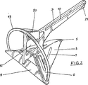
以下、図面を詳細に参照するに、総称的に1で示される本発明によるアンカーは、好ましくは、中央の垂直に配置される面に関して実質的に対称的な形状を有している(例えば、図3および5を参照)。アンカー1は、図示される好ましい実施形態において、平面視で互いに対向する実質的に三角形状の翼部材3および4から形成されるベース部材としての第1錨爪2を備えている。これらの翼部材3および4の各々は、その頂点またはその頂点の近傍に、各翼部材3、4の全面から下方に延在するような形を有する下向き部分5を有し、これによって、第1錨爪2の先端(従って、アンカーの先端)に、関係する把駐地内にアンカーの全体を掘込むのを容易にし、そこへの適切な錨泊を確実にする機能を有する部分を与える。各翼部材3、4の他端、換言すれば、先端または頂点およびその関係する下向き部分5から遠い端に、翼部材3、4の全面から上方かつ後方に90°以外の角度で突出する後方突出部材6が設けられている。
Referring now in detail to the drawings, the anchor according to the invention, generally designated 1, preferably has a substantially symmetric shape with respect to a central vertically arranged plane (e.g. (See FIGS. 3 and 5). The anchor 1 is provided with a
図示される好ましい実施形態において、各翼部材3、4は、アンカー1の全体の自由側端を構成する最長側部を有している。翼部材3、4は、それらの一つの側に沿って、互いにある角度をなして接続されている。各翼部材3、4は平面ではない。翼部材3、4は、実際、第1錨爪2が端面視で実質的にV形状に形成されるように、互いにある角度をなして配置されている。
In the preferred embodiment shown, each
第1錨爪2は、好ましくは、任意の公知の装置を用いて、任意の公知の方法によって、適切な金属の単一シートから形成される。 The first Ikaritsume 2 preferably using any known device, by any known method, are formed from a single sheet of suitable metal.
図面に示されるように、第1錨爪2のそれぞれの翼部材3、4、および好ましくはそれらの後方突出部材6は、各々、1つ以上の細長スロット7による不連続部を備えている。このようなスロット7は、そこに水を通過させることによって急速にアンカー1を沈降させるのを補助する、ことが見出されている。アンカー1をその把駐地から離脱することが望まれるとき、これらのスロット7の存在は、アンカー1をその場に維持するように作用する吸引効果を中断させるのを促進し、所望のときに、アンカー全体の離脱を容易にする。これらのスロット7の存在そのものが、ある種のポンピング作用をも生じさせ、さらに詳細には、アンカー1が荒波および/または風の吹く天気において使用される場合、砂や泥などをアンカー1の下から移動させ、全体的に良好な錨泊を可能とする。
As shown in the drawings, each
アンカー1の実質的に横方向において、その後部、すなわち、先端ではない側の端に向かって延在しているのは、押さえ部材8である。このような押さえ部材8は、第1錨爪2と一体に形成されるか、さらに好ましくは、溶接によってそれと結合されるとよい。図示される特に好ましい実施形態において、この押さえ部材8は、アンカー全体の実質的に横方向に延在している。押さえ部材8は、実質的に平面形状であり、両側の固定端が、任意の適切な方法、例えば、溶接によって、後方突出部材6に固着されている。
In the substantially lateral direction of the anchor 1, it is the pressing member 8 that extends toward the rear portion, that is, the end that is not the tip. Such a pressing member 8 may be formed integrally with the
図示される好ましい実施形態において、本発明によるアンカー1は、総称的に9で示されるシャンク部材を備えている。このシャンク部材9は、任意の適切な手段、例えば、溶接によって、第1錨爪2および押さえ部材8の両方に固定して取り付けられている。
In the preferred embodiment shown, the anchor 1 according to the invention comprises a shank member, generally designated 9. The shank member 9 is fixedly attached to both the
図示される特に好ましい実施形態において、シャンク部材9は、好ましくはアンカー1の第1錨爪2と実質的に平行に延在してそこから離間している細長アーム部10と、第1錨爪2に取り付けられる脚部材11を備えている。好ましくは、脚部材11は、例えば、溶接によって、押さえ部材8および第1錨爪2の両方と物理的に接続または接触するような形状を有し、シャンク部材9の全体は、第1錨爪2、換言すれば、アンカー全体の実質的に中心に配置されている。シャンク部材9の脚部材11は、大きい空洞による不連続部12を有している。このような不連続部12はアンカー1の全重量を低減し、同時にその有効性を増加させる。
In the particularly preferred embodiment shown, the shank member 9 comprises an
また、図示される好ましい実施形態において、本発明によるアンカー1は、好ましくは、そのアンカーに結合され、アンカーの全体のバランスを取り、または自己直立するのを補助する安定化手段を備えている。好ましくは、これは、図示されるような実質的に半円形状を有するフープ状部材13の形態をとることができる。このフープ状部材13は、離脱可能または永久的に、任意の適切な手段を用いて、任意の公知の方法によって、例えば、溶接を用いて、第1錨爪2に固定することができる。
Also, in the preferred embodiment shown, the anchor 1 according to the invention is preferably provided with stabilizing means which are coupled to the anchor and help to balance the whole of the anchor or to stand upright. Preferably, this can take the form of a hoop-
図示されない本発明の1つの好ましい実施形態において、自己直立させるためのフープ状部材13は、第1錨爪2に離脱可能に取り付けられてもよい。
In one preferred embodiment of the present invention (not shown), the hoop-
図示される好ましい実施形態において、シャンク部材9のアーム部10は、その長手方向に延長する異形スロット14を備え、このスロット14は、シャックルまたは類似の手段、例えば、D−シャックルを受け、好ましくは、離脱可能に保持するように構成されている。この装置は、本特許出願人によるオーストラリア特許第734943号明細書に詳細に記載されている方法によって操作し、必要なときに、アンカーを自動的に再配置することができるようにされている。
In the preferred embodiment shown, the
本発明によるアンカー1は、第1錨爪2から離間し、実質的にそれと平行に配置された第2錨爪20を備えている。図示されない一実施形態において、第2錨爪20はシャンク部材9の細長アーム部10の最上自由表面に対し、任意の公知の方法、例えば、溶接によって、そこに接続されるとよい。しかし、特に好ましい実施形態において、例えば、図1に示されるように、第2錨爪20は、フープ状部材13とシャンク部材9との間に延在するように構成されている。この点に関して、図示される好ましい実施形態において、フープ状部材13は、その最上端において、任意の適切な手段および任意の適切な方法、例えば、溶接によって、シャンク部材9の後部に固着される。第2錨爪20は、このフープ状部材13と、第1錨爪2と実質的に平行に配置されるように構成されているシャンク部材9との間に延在する。
The anchor 1 according to the present invention comprises a
使用中、本発明によるアンカー1は、その関係する把駐地に埋め込まれるように意図されている。しかし、アンカーをその把駐地から離脱させる場合、アンカーラインの先端のD−シャックル(不図示)は、スロット14の端に突き当たる時間まで、スロット14に沿って走行するように動作する。この点に関して、この動作は、勿論、限られた時間内に行なわれるが、実質的に、D−シャックルはかなり大きな力でスロット14に突き当たることになる。
In use, the anchor 1 according to the present invention is intended to be embedded in its associated custody. However, when the anchor is removed from its holding location, the D-shackle (not shown) at the tip of the anchor line operates to travel along the
上記シャンク部材9のアーム部10の自由端またはその自由端の近傍において、そのアーム部10の長さに沿って、任意の種類または形状(例えば、ピンなど)の突起21が含目的的に配置されるとよい。使用中、この突起21はD−シャックルがシャンク部材9に沿って移動するかまたはそこから下方に落ちる、さらに具体的には、その下側に沿って移動するのを防ぐ。この観点から、もしこのようなことが許容されると、シャックルおよびその関連チェーン、ケーブル、チェーンロープなど(集約的にアンカーラインと呼ぶ、図示せず)がシャンク部材9上で詰まるかまたはもつれ、アンカー1の全体の正しい方向付けを妨げるものである。
In the free end of the
代替的実施形態において、スロット14は、傾斜した中間または接続部分を有さず、その全長に沿って実質的に平らに延在している。さらに、D−シャックルおよびその関連する鎖の詰まりまたはもつれを防ぐための突起21を用いるよりはむしろ、異形部材がシャンク部材9の端またはその近傍に設けられる。この異形部材も、D−シャックルがシャンク部材9の自由端の周囲を移動するのを防ぐように作動する。
In an alternative embodiment, the
大部分の重量をシャンク部材9の自由端から遠い端に有するアンカー1の全体的な形状と配置によって、スロット14の端へのD−シャックルの突当りがアンカー1を上げ起こす(さらに正確には、上げ起こすように強制する)。この位置または配置にあるとき、D−シャックルは、スロット14に沿って逆方向に走行し、その他端に戻り、アンカー1の全体を連れ戻し、アンカー1の背部を持ち上げ、それによって、アンカー1の全体を把駐地内に再設置することを可能とする。この動作の全体は、いかなる人の介入も必要とせず、自動的に行なわれる。これが、水面へのアンカーの引き上げ、それに続く再設置を必要とするこれまでに採用されている先行技術の手順と、著しく異なっている。
Due to the overall shape and arrangement of the anchor 1 having the most weight at the end far from the free end of the shank member 9, the abutment of the D-shackle at the end of the
第2錨爪20を利用する、または採用する本発明によるアンカー1は、公知の技術と比較して、多くの重要な実用的利点を有する。
The anchor 1 according to the invention that utilizes or employs the
まず、試験によって、船舶の側部を越えて投入されたとき、本発明によるアンカー1は、それ自身が直立し、関係する把駐地の表面にまず正立で着地し、それによって、最初に投入されたときのアンカー1の実際の空間的な配置とは無関係に、アンカーの埋込みを確実にすることが明らかになっている。このようなことは、アンカー1を実際に配置する担当者の「技術」または経験とは無関係に、改良された適切な錨泊が達成されることを意味する。事実、満足すべき結果を達成するのに、どのような技術または実際的な経験も必要としない。これが、先行技術のアンカーと異なっている。 First, when loaded across the side of a ship by testing, the anchor 1 according to the invention stands upright itself and first lands upright on the surface of the relevant holding place, thereby the first loading It has been shown to ensure anchor embedding regardless of the actual spatial arrangement of the anchor 1 when done. This means that a suitable improved anchorage can be achieved irrespective of the “technique” or experience of the person who actually places the anchor 1. In fact, no skill or practical experience is required to achieve satisfactory results. This is different from the prior art anchors .
本発明のアンカー1は、その構成自身によって、所定の把駐地に存在し得る雑草などに絡まる、または捕捉される可能性に対して実質的に耐えられる。第2錨爪20は、泥および他の非本質的かつ不必要な材料がアンカー1の自己直立フープ状部材13および関係するシャンク部材9上に堆積するのを防ぎ、それによって、所望のときに、アンカーを把駐地から簡単に離脱させることができることを確実にするように、作用する。
The anchor 1 of the present invention can substantially withstand the possibility of being entangled or caught by weeds or the like that may exist in a predetermined holding place by the configuration itself. The
本発明のアンカー1において、第1錨爪2は、同様の先行技術の装置と比較して、寸法の全体がより小さくなるように切り詰められている。これによって、アンカー1の先端は、より迅速かつより簡単に、所定の把駐地に掘込まれる。
In the anchor 1 of the present invention , the
過去に、アンカー1が泥などの中で逆さまに引き摺られて把駐地を形成する場合があった。離間する第1錨爪2および第2錨爪20を有する本発明のアンカー1は、アンカーが逆さまの状態でなんとか配置された場合であっても、水圧がアンカー1の全体を泥などから引き上げるのを補助するように作用するように構成されている。
In the past, the anchor 1 was dragged upside down in mud or the like to form a holding place. In the anchor 1 of the present invention having the
先行技術のアンカー、例えば、本特許出願人のオーストラリア特許第734943号明細書の主題であるアンカーは、使用時において、かなりの量の雑草および類似の材料が蓄積し得るという実際的な欠点で悩まされていたことがわかっている。このような堆積または蓄積の結果、アンカーは適切に直立することができない。本発明のアンカー1のように第2錨爪20によって保護されていない場合、例えば、自己直立フープ状部材13は、当然のことではあるが、簡単に1個の岩礁の全体を覆って取り付き、すなわち、「引っ掛かって」、簡単に離脱かつ自己直立するのを妨げられる。
Prior art anchors, such as the subject matter of the Applicant's Australian Patent No. 734943, suffer from the practical disadvantage that in use, a significant amount of weeds and similar materials can accumulate. I know that was done. As a result of such deposition or accumulation, the anchor cannot properly stand upright. In the case where it is not protected by the
例えば、軟質な泥のような把駐地内において、アンカー1が上下逆さまに位置したとき、第2錨爪20は、アンカーの全体が船舶によって引き摺られるときに、上昇装置として作用する。実際、泥は第2錨爪自身の前方に押し出され、その結果、アンカーを泥から引き上げ、それによって、アンカーを反転し、必要に応じて、適切に設置または離脱させることが可能になる。
For example, when the anchor 1 is positioned upside down in a holding place such as soft mud, the
さらに、アンカー1が砂の把駐地に埋め込まれるとき、第2錨爪20は、全体の把駐力を高め、アンカー全体に作用する下向き力を生じさせる。第2錨爪20の存在によるこの付加的な下向きに作用する力は、アンカーを把駐地から引出させずに、または分離させずに完全に360°にわたって実質的に旋回させることができる程度まで、アンカー全体の性能を増加させることが見出されている。このように、本発明のアンカーは、特に係留の目的に適している。
Furthermore, when the anchor 1 is embedded in the sand holding place, the
最後に、以上の説明は単に本特許出願人の装置の好適な実施形態に言及したものであって、特許請求の範囲によって限界が定められる本発明の精神と範囲から逸脱することなく、それらの実施形態に対する変形および修正が可能であることが理解されるべきである。 Finally, the foregoing description merely refers to the preferred embodiment of the Applicant's apparatus and is intended to be used without departing from the spirit and scope of the invention as defined by the appended claims. It should be understood that variations and modifications to the embodiments are possible.
Claims (16)
前記第1錨爪に固定して取り付けられ、少なくとも1つのアンカーラインを保持するように構成されている細長シャンク部材と、
前記第1錨爪に取り付けられ、実質的に半円形状であり、前記アンカーが簡単に動作配置に着き、かつ前記動作配置から均衡が乱された後でも前記動作配置に復帰するのを確実にするように機能するフープ状部材と、
前記シャンク部材の最上面および前記フープ状部材の両方に固定され、前記第1錨爪から離間され、該第1錨爪と実質的に平行に配置される第2錨爪とを備え、
前記第2錨爪は前記第1錨爪よりも小さい寸法を有することを特徴とするアンカー。 One end constitutes the tip of the anchor, a first Ikaritsume as a base member that is configured to assist in anchoring / implantation of the anchor in a given bunch stationed land,
Fixedly attached to the first Ikaritsume, an elongate shank member configured to at least one anchor line to retain,
It is attached to the first claw and is substantially semi-circular in shape so that the anchor can easily reach the operating configuration and return to the operating configuration even after the balance is disturbed from the operating configuration. A hoop-like member that functions to
Fixed to said both the top and the hoop-shaped member of the shank member, spaced from the first anchor pawl, and a second Ikaritsume which is substantially parallel to the first Ikaritsume,
The anchor characterized in that the second claw has a smaller size than the first claw.
Applications Claiming Priority (2)
| Application Number | Priority Date | Filing Date | Title |
|---|---|---|---|
| AUPS3014A AUPS301402A0 (en) | 2002-06-18 | 2002-06-18 | Improvements in anchors |
| PCT/AU2003/000800 WO2003106252A1 (en) | 2002-06-18 | 2003-06-16 | Anchor with smaller second fluke |
Publications (2)
| Publication Number | Publication Date |
|---|---|
| JP2005529790A JP2005529790A (en) | 2005-10-06 |
| JP4399358B2 true JP4399358B2 (en) | 2010-01-13 |
Family
ID=3836575
Family Applications (1)
| Application Number | Title | Priority Date | Filing Date |
|---|---|---|---|
| JP2004513102A Expired - Fee Related JP4399358B2 (en) | 2002-06-18 | 2003-06-16 | Anchor with a small second claw |
Country Status (8)
| Country | Link |
|---|---|
| US (1) | US7111576B2 (en) |
| EP (1) | EP1517829B1 (en) |
| JP (1) | JP4399358B2 (en) |
| CN (1) | CN100390018C (en) |
| AU (1) | AUPS301402A0 (en) |
| CA (1) | CA2488506C (en) |
| NZ (1) | NZ537011A (en) |
| WO (1) | WO2003106252A1 (en) |
Families Citing this family (10)
| Publication number | Priority date | Publication date | Assignee | Title |
|---|---|---|---|---|
| US8205569B2 (en) * | 2007-03-27 | 2012-06-26 | Rex William Francis | Anchor |
| GB2463912B (en) * | 2008-09-30 | 2012-09-26 | John Henderson Knox | Rigid marine anchor with roll stability flanges |
| GB201006362D0 (en) * | 2010-04-16 | 2010-06-02 | Brupat Ltd | Offshore marine anchor |
| US20130036963A1 (en) * | 2011-08-09 | 2013-02-14 | Gregory Kutsen | High-penetration, high-holding power, stowable marine anchor |
| US8950352B2 (en) * | 2011-09-16 | 2015-02-10 | Peter Kevin Smith | Anchor |
| AU2012247025B2 (en) * | 2011-11-09 | 2014-02-13 | Manson Anchors Limited | An anchor system |
| CN106697198B (en) * | 2016-12-16 | 2018-07-27 | 浙江海洋大学东海科学技术学院 | A kind of mooring positioning device |
| CN110481710A (en) * | 2019-09-24 | 2019-11-22 | 东营鑫奥船舶设备制造有限公司 | A kind of chute-type triangle anchor |
| CN110979563A (en) * | 2019-12-16 | 2020-04-10 | 国家海洋局北海海洋环境监测中心站 | Buoy for ocean observation |
| CN112529034B (en) * | 2020-10-24 | 2021-11-16 | 中极华盛工程咨询有限公司 | Micro-control operating system and method using parameter identification |
Family Cites Families (9)
| Publication number | Priority date | Publication date | Assignee | Title |
|---|---|---|---|---|
| JPS5675287A (en) * | 1979-11-24 | 1981-06-22 | Sojiro Nakamura | Anchor for fishing boat |
| FI71701C (en) * | 1980-09-25 | 1987-02-09 | Den Haak Rob Van | Ankare. |
| US4433635A (en) * | 1980-11-19 | 1984-02-28 | Kyuroku Corporation | Single fluke anchor |
| CA1278725C (en) | 1985-09-27 | 1991-01-08 | Rob Van Den Haak | Anchor |
| CN86100338A (en) * | 1986-01-21 | 1987-08-05 | 罗布·万·丹·哈克 | Anchor |
| US5469802A (en) * | 1994-06-22 | 1995-11-28 | Ivicevic; Dragomir | Boat anchor |
| US6082284A (en) * | 1996-11-04 | 2000-07-04 | Vrijhof Ankers Beheer B.V. | Anchor |
| AU734943B2 (en) | 1997-09-10 | 2001-06-28 | Rex William Francis | Improvements in anchors |
| NZ331750A (en) * | 1997-09-10 | 2000-01-28 | William Francis Rex | Anchor comprises a base, a shank and stabilizing means |
-
2002
- 2002-06-18 AU AUPS3014A patent/AUPS301402A0/en not_active Abandoned
-
2003
- 2003-06-16 CN CNB038142635A patent/CN100390018C/en not_active Expired - Fee Related
- 2003-06-16 EP EP03729723.1A patent/EP1517829B1/en not_active Expired - Lifetime
- 2003-06-16 CA CA2488506A patent/CA2488506C/en not_active Expired - Lifetime
- 2003-06-16 NZ NZ537011A patent/NZ537011A/en not_active IP Right Cessation
- 2003-06-16 WO PCT/AU2003/000800 patent/WO2003106252A1/en active Application Filing
- 2003-06-16 US US10/517,996 patent/US7111576B2/en not_active Expired - Lifetime
- 2003-06-16 JP JP2004513102A patent/JP4399358B2/en not_active Expired - Fee Related
Also Published As
| Publication number | Publication date |
|---|---|
| AUPS301402A0 (en) | 2002-07-11 |
| CA2488506A1 (en) | 2003-12-24 |
| CN1662415A (en) | 2005-08-31 |
| EP1517829B1 (en) | 2015-04-15 |
| JP2005529790A (en) | 2005-10-06 |
| US7111576B2 (en) | 2006-09-26 |
| EP1517829A1 (en) | 2005-03-30 |
| WO2003106252A1 (en) | 2003-12-24 |
| CN100390018C (en) | 2008-05-28 |
| US20050247253A1 (en) | 2005-11-10 |
| NZ537011A (en) | 2008-07-31 |
| EP1517829A4 (en) | 2006-10-04 |
| CA2488506C (en) | 2010-09-14 |
Similar Documents
| Publication | Publication Date | Title |
|---|---|---|
| JP4399358B2 (en) | Anchor with a small second claw | |
| US7886681B2 (en) | Anchor retrieval device, system and method | |
| JP6293865B2 (en) | Water anchor | |
| EP2129573B1 (en) | Improved anchor | |
| US6038996A (en) | Modular boat anchor and kit | |
| US4303037A (en) | Single point mooring system | |
| US5970902A (en) | Anchors | |
| US9061741B2 (en) | Anchor positioning system | |
| US20190300126A1 (en) | Watercraft anchors | |
| US20110094432A1 (en) | Gravity anchor | |
| WO2007101311A1 (en) | Sea anchor | |
| US20100326344A1 (en) | Anchor retrieval device, system and method | |
| US4708086A (en) | Boat anchor | |
| JP4052717B2 (en) | Throwing device and throwing method | |
| AU734943B2 (en) | Improvements in anchors | |
| JP3177807U (en) | Rocky sandy combined anchor | |
| US5398633A (en) | Tautline boat mooring system | |
| AU2003240308A1 (en) | Anchor with smaller second fluke | |
| AU2023204710A1 (en) | Plate anchor | |
| JPS5939893Y2 (en) | floating fish reef | |
| JPS5849234Y2 (en) | Oil fence fitting | |
| EP2721222A1 (en) | Device and method of gathering a mass in a body of water | |
| US20040154521A1 (en) | Folding anchor | |
| JP2003226288A (en) | Mooring rope | |
| JPH0713693U (en) | A small vessel with a tail fin |
Legal Events
| Date | Code | Title | Description |
|---|---|---|---|
| A621 | Written request for application examination |
Free format text: JAPANESE INTERMEDIATE CODE: A621 Effective date: 20060529 |
|
| A131 | Notification of reasons for refusal |
Free format text: JAPANESE INTERMEDIATE CODE: A131 Effective date: 20081218 |
|
| A521 | Request for written amendment filed |
Free format text: JAPANESE INTERMEDIATE CODE: A523 Effective date: 20090316 |
|
| TRDD | Decision of grant or rejection written | ||
| A01 | Written decision to grant a patent or to grant a registration (utility model) |
Free format text: JAPANESE INTERMEDIATE CODE: A01 Effective date: 20091001 |
|
| A01 | Written decision to grant a patent or to grant a registration (utility model) |
Free format text: JAPANESE INTERMEDIATE CODE: A01 |
|
| A61 | First payment of annual fees (during grant procedure) |
Free format text: JAPANESE INTERMEDIATE CODE: A61 Effective date: 20091026 |
|
| FPAY | Renewal fee payment (event date is renewal date of database) |
Free format text: PAYMENT UNTIL: 20121030 Year of fee payment: 3 |
|
| R150 | Certificate of patent or registration of utility model |
Ref document number: 4399358 Country of ref document: JP Free format text: JAPANESE INTERMEDIATE CODE: R150 Free format text: JAPANESE INTERMEDIATE CODE: R150 |
|
| FPAY | Renewal fee payment (event date is renewal date of database) |
Free format text: PAYMENT UNTIL: 20121030 Year of fee payment: 3 |
|
| FPAY | Renewal fee payment (event date is renewal date of database) |
Free format text: PAYMENT UNTIL: 20131030 Year of fee payment: 4 |
|
| R250 | Receipt of annual fees |
Free format text: JAPANESE INTERMEDIATE CODE: R250 |
|
| R250 | Receipt of annual fees |
Free format text: JAPANESE INTERMEDIATE CODE: R250 |
|
| R250 | Receipt of annual fees |
Free format text: JAPANESE INTERMEDIATE CODE: R250 |
|
| R250 | Receipt of annual fees |
Free format text: JAPANESE INTERMEDIATE CODE: R250 |
|
| R250 | Receipt of annual fees |
Free format text: JAPANESE INTERMEDIATE CODE: R250 |
|
| R250 | Receipt of annual fees |
Free format text: JAPANESE INTERMEDIATE CODE: R250 |
|
| R250 | Receipt of annual fees |
Free format text: JAPANESE INTERMEDIATE CODE: R250 |
|
| LAPS | Cancellation because of no payment of annual fees |