JP4398372B2 - Conduit and method for forming the same - Google Patents
Conduit and method for forming the same Download PDFInfo
- Publication number
- JP4398372B2 JP4398372B2 JP2004535295A JP2004535295A JP4398372B2 JP 4398372 B2 JP4398372 B2 JP 4398372B2 JP 2004535295 A JP2004535295 A JP 2004535295A JP 2004535295 A JP2004535295 A JP 2004535295A JP 4398372 B2 JP4398372 B2 JP 4398372B2
- Authority
- JP
- Japan
- Prior art keywords
- ribbon
- conduit
- crease
- film
- folded
- Prior art date
- Legal status (The legal status is an assumption and is not a legal conclusion. Google has not performed a legal analysis and makes no representation as to the accuracy of the status listed.)
- Expired - Fee Related
Links
- 238000000034 method Methods 0.000 title claims abstract description 39
- 239000004020 conductor Substances 0.000 claims abstract description 49
- 229920000642 polymer Polymers 0.000 claims abstract description 16
- 238000004804 winding Methods 0.000 claims abstract description 9
- 239000011324 bead Substances 0.000 claims description 48
- 239000000463 material Substances 0.000 claims description 27
- 238000010438 heat treatment Methods 0.000 claims description 17
- 238000003466 welding Methods 0.000 claims description 17
- 239000004033 plastic Substances 0.000 claims description 12
- NLYAJNPCOHFWQQ-UHFFFAOYSA-N kaolin Chemical compound O.O.O=[Al]O[Si](=O)O[Si](=O)O[Al]=O NLYAJNPCOHFWQQ-UHFFFAOYSA-N 0.000 claims description 3
- 238000010924 continuous production Methods 0.000 abstract 1
- 239000010408 film Substances 0.000 description 158
- 239000010410 layer Substances 0.000 description 18
- 230000003014 reinforcing effect Effects 0.000 description 11
- 238000004519 manufacturing process Methods 0.000 description 10
- 230000015572 biosynthetic process Effects 0.000 description 5
- 230000029058 respiratory gaseous exchange Effects 0.000 description 5
- 238000001816 cooling Methods 0.000 description 4
- 239000002985 plastic film Substances 0.000 description 4
- 229920006255 plastic film Polymers 0.000 description 4
- 229910001220 stainless steel Inorganic materials 0.000 description 4
- 239000010935 stainless steel Substances 0.000 description 4
- XLYOFNOQVPJJNP-UHFFFAOYSA-N water Chemical compound O XLYOFNOQVPJJNP-UHFFFAOYSA-N 0.000 description 4
- 238000010586 diagram Methods 0.000 description 3
- 230000000241 respiratory effect Effects 0.000 description 3
- 238000003860 storage Methods 0.000 description 3
- 239000010409 thin film Substances 0.000 description 3
- 230000007423 decrease Effects 0.000 description 2
- 239000011810 insulating material Substances 0.000 description 2
- 239000000155 melt Substances 0.000 description 2
- 239000012528 membrane Substances 0.000 description 2
- 230000007935 neutral effect Effects 0.000 description 2
- 208000001797 obstructive sleep apnea Diseases 0.000 description 2
- 230000002787 reinforcement Effects 0.000 description 2
- 201000002859 sleep apnea Diseases 0.000 description 2
- 208000031481 Pathologic Constriction Diseases 0.000 description 1
- 238000009825 accumulation Methods 0.000 description 1
- XAGFODPZIPBFFR-UHFFFAOYSA-N aluminium Chemical compound [Al] XAGFODPZIPBFFR-UHFFFAOYSA-N 0.000 description 1
- 229910052782 aluminium Inorganic materials 0.000 description 1
- 238000005452 bending Methods 0.000 description 1
- 229920001400 block copolymer Polymers 0.000 description 1
- 230000005494 condensation Effects 0.000 description 1
- 238000009833 condensation Methods 0.000 description 1
- 238000011513 continuous positive airway pressure therapy Methods 0.000 description 1
- 239000006260 foam Substances 0.000 description 1
- 239000012212 insulator Substances 0.000 description 1
- 238000005304 joining Methods 0.000 description 1
- 238000002844 melting Methods 0.000 description 1
- 230000008018 melting Effects 0.000 description 1
- 238000010309 melting process Methods 0.000 description 1
- 238000012544 monitoring process Methods 0.000 description 1
- 229920000728 polyester Polymers 0.000 description 1
- 229920006254 polymer film Polymers 0.000 description 1
- 239000002861 polymer material Substances 0.000 description 1
- 238000003825 pressing Methods 0.000 description 1
- 230000001568 sexual effect Effects 0.000 description 1
- 229920002379 silicone rubber Polymers 0.000 description 1
- 239000004945 silicone rubber Substances 0.000 description 1
- 208000037804 stenosis Diseases 0.000 description 1
- 230000036262 stenosis Effects 0.000 description 1
- 239000002344 surface layer Substances 0.000 description 1
- 238000009423 ventilation Methods 0.000 description 1
Images


Classifications
-
- B—PERFORMING OPERATIONS; TRANSPORTING
- B29—WORKING OF PLASTICS; WORKING OF SUBSTANCES IN A PLASTIC STATE IN GENERAL
- B29C—SHAPING OR JOINING OF PLASTICS; SHAPING OF MATERIAL IN A PLASTIC STATE, NOT OTHERWISE PROVIDED FOR; AFTER-TREATMENT OF THE SHAPED PRODUCTS, e.g. REPAIRING
- B29C53/00—Shaping by bending, folding, twisting, straightening or flattening; Apparatus therefor
- B29C53/02—Bending or folding
- B29C53/04—Bending or folding of plates or sheets
- B29C53/06—Forming folding lines by pressing or scoring
- B29C53/063—Forming folding lines by pressing or scoring combined with folding
-
- A—HUMAN NECESSITIES
- A61—MEDICAL OR VETERINARY SCIENCE; HYGIENE
- A61M—DEVICES FOR INTRODUCING MEDIA INTO, OR ONTO, THE BODY; DEVICES FOR TRANSDUCING BODY MEDIA OR FOR TAKING MEDIA FROM THE BODY; DEVICES FOR PRODUCING OR ENDING SLEEP OR STUPOR
- A61M16/00—Devices for influencing the respiratory system of patients by gas treatment, e.g. mouth-to-mouth respiration; Tracheal tubes
- A61M16/08—Bellows; Connecting tubes ; Water traps; Patient circuits
- A61M16/0875—Connecting tubes
-
- B—PERFORMING OPERATIONS; TRANSPORTING
- B29—WORKING OF PLASTICS; WORKING OF SUBSTANCES IN A PLASTIC STATE IN GENERAL
- B29C—SHAPING OR JOINING OF PLASTICS; SHAPING OF MATERIAL IN A PLASTIC STATE, NOT OTHERWISE PROVIDED FOR; AFTER-TREATMENT OF THE SHAPED PRODUCTS, e.g. REPAIRING
- B29C53/00—Shaping by bending, folding, twisting, straightening or flattening; Apparatus therefor
- B29C53/36—Bending and joining, e.g. for making hollow articles
-
- B—PERFORMING OPERATIONS; TRANSPORTING
- B29—WORKING OF PLASTICS; WORKING OF SUBSTANCES IN A PLASTIC STATE IN GENERAL
- B29C—SHAPING OR JOINING OF PLASTICS; SHAPING OF MATERIAL IN A PLASTIC STATE, NOT OTHERWISE PROVIDED FOR; AFTER-TREATMENT OF THE SHAPED PRODUCTS, e.g. REPAIRING
- B29C53/00—Shaping by bending, folding, twisting, straightening or flattening; Apparatus therefor
- B29C53/56—Winding and joining, e.g. winding spirally
- B29C53/58—Winding and joining, e.g. winding spirally helically
- B29C53/581—Winding and joining, e.g. winding spirally helically using sheets or strips consisting principally of plastics material
- B29C53/582—Winding and joining, e.g. winding spirally helically using sheets or strips consisting principally of plastics material comprising reinforcements, e.g. wires, threads
-
- B—PERFORMING OPERATIONS; TRANSPORTING
- B29—WORKING OF PLASTICS; WORKING OF SUBSTANCES IN A PLASTIC STATE IN GENERAL
- B29C—SHAPING OR JOINING OF PLASTICS; SHAPING OF MATERIAL IN A PLASTIC STATE, NOT OTHERWISE PROVIDED FOR; AFTER-TREATMENT OF THE SHAPED PRODUCTS, e.g. REPAIRING
- B29C53/00—Shaping by bending, folding, twisting, straightening or flattening; Apparatus therefor
- B29C53/56—Winding and joining, e.g. winding spirally
- B29C53/58—Winding and joining, e.g. winding spirally helically
- B29C53/60—Winding and joining, e.g. winding spirally helically using internal forming surfaces, e.g. mandrels
- B29C53/607—Winding and joining, e.g. winding spirally helically using internal forming surfaces, e.g. mandrels having driving means for advancing the wound articles, e.g. belts, rolls
-
- B—PERFORMING OPERATIONS; TRANSPORTING
- B29—WORKING OF PLASTICS; WORKING OF SUBSTANCES IN A PLASTIC STATE IN GENERAL
- B29C—SHAPING OR JOINING OF PLASTICS; SHAPING OF MATERIAL IN A PLASTIC STATE, NOT OTHERWISE PROVIDED FOR; AFTER-TREATMENT OF THE SHAPED PRODUCTS, e.g. REPAIRING
- B29C53/00—Shaping by bending, folding, twisting, straightening or flattening; Apparatus therefor
- B29C53/56—Winding and joining, e.g. winding spirally
- B29C53/58—Winding and joining, e.g. winding spirally helically
- B29C53/78—Winding and joining, e.g. winding spirally helically using profiled sheets or strips
- B29C53/785—Winding and joining, e.g. winding spirally helically using profiled sheets or strips with reinforcements
-
- B—PERFORMING OPERATIONS; TRANSPORTING
- B29—WORKING OF PLASTICS; WORKING OF SUBSTANCES IN A PLASTIC STATE IN GENERAL
- B29C—SHAPING OR JOINING OF PLASTICS; SHAPING OF MATERIAL IN A PLASTIC STATE, NOT OTHERWISE PROVIDED FOR; AFTER-TREATMENT OF THE SHAPED PRODUCTS, e.g. REPAIRING
- B29C63/00—Lining or sheathing, i.e. applying preformed layers or sheathings of plastics; Apparatus therefor
- B29C63/0004—Component parts, details or accessories; Auxiliary operations
- B29C63/0013—Removing old coatings
-
- B—PERFORMING OPERATIONS; TRANSPORTING
- B29—WORKING OF PLASTICS; WORKING OF SUBSTANCES IN A PLASTIC STATE IN GENERAL
- B29C—SHAPING OR JOINING OF PLASTICS; SHAPING OF MATERIAL IN A PLASTIC STATE, NOT OTHERWISE PROVIDED FOR; AFTER-TREATMENT OF THE SHAPED PRODUCTS, e.g. REPAIRING
- B29C65/00—Joining or sealing of preformed parts, e.g. welding of plastics materials; Apparatus therefor
- B29C65/02—Joining or sealing of preformed parts, e.g. welding of plastics materials; Apparatus therefor by heating, with or without pressure
- B29C65/40—Applying molten plastics, e.g. hot melt
-
- B—PERFORMING OPERATIONS; TRANSPORTING
- B29—WORKING OF PLASTICS; WORKING OF SUBSTANCES IN A PLASTIC STATE IN GENERAL
- B29C—SHAPING OR JOINING OF PLASTICS; SHAPING OF MATERIAL IN A PLASTIC STATE, NOT OTHERWISE PROVIDED FOR; AFTER-TREATMENT OF THE SHAPED PRODUCTS, e.g. REPAIRING
- B29C66/00—General aspects of processes or apparatus for joining preformed parts
- B29C66/01—General aspects dealing with the joint area or with the area to be joined
- B29C66/05—Particular design of joint configurations
- B29C66/10—Particular design of joint configurations particular design of the joint cross-sections
- B29C66/11—Joint cross-sections comprising a single joint-segment, i.e. one of the parts to be joined comprising a single joint-segment in the joint cross-section
- B29C66/112—Single lapped joints
- B29C66/1122—Single lap to lap joints, i.e. overlap joints
-
- B—PERFORMING OPERATIONS; TRANSPORTING
- B29—WORKING OF PLASTICS; WORKING OF SUBSTANCES IN A PLASTIC STATE IN GENERAL
- B29C—SHAPING OR JOINING OF PLASTICS; SHAPING OF MATERIAL IN A PLASTIC STATE, NOT OTHERWISE PROVIDED FOR; AFTER-TREATMENT OF THE SHAPED PRODUCTS, e.g. REPAIRING
- B29C66/00—General aspects of processes or apparatus for joining preformed parts
- B29C66/01—General aspects dealing with the joint area or with the area to be joined
- B29C66/05—Particular design of joint configurations
- B29C66/10—Particular design of joint configurations particular design of the joint cross-sections
- B29C66/13—Single flanged joints; Fin-type joints; Single hem joints; Edge joints; Interpenetrating fingered joints; Other specific particular designs of joint cross-sections not provided for in groups B29C66/11 - B29C66/12
- B29C66/135—Single hemmed joints, i.e. one of the parts to be joined being hemmed in the joint area
-
- B—PERFORMING OPERATIONS; TRANSPORTING
- B29—WORKING OF PLASTICS; WORKING OF SUBSTANCES IN A PLASTIC STATE IN GENERAL
- B29C—SHAPING OR JOINING OF PLASTICS; SHAPING OF MATERIAL IN A PLASTIC STATE, NOT OTHERWISE PROVIDED FOR; AFTER-TREATMENT OF THE SHAPED PRODUCTS, e.g. REPAIRING
- B29C66/00—General aspects of processes or apparatus for joining preformed parts
- B29C66/01—General aspects dealing with the joint area or with the area to be joined
- B29C66/349—Cooling the welding zone on the welding spot
-
- B—PERFORMING OPERATIONS; TRANSPORTING
- B29—WORKING OF PLASTICS; WORKING OF SUBSTANCES IN A PLASTIC STATE IN GENERAL
- B29C—SHAPING OR JOINING OF PLASTICS; SHAPING OF MATERIAL IN A PLASTIC STATE, NOT OTHERWISE PROVIDED FOR; AFTER-TREATMENT OF THE SHAPED PRODUCTS, e.g. REPAIRING
- B29C66/00—General aspects of processes or apparatus for joining preformed parts
- B29C66/40—General aspects of joining substantially flat articles, e.g. plates, sheets or web-like materials; Making flat seams in tubular or hollow articles; Joining single elements to substantially flat surfaces
- B29C66/41—Joining substantially flat articles ; Making flat seams in tubular or hollow articles
- B29C66/43—Joining a relatively small portion of the surface of said articles
- B29C66/431—Joining the articles to themselves
-
- B—PERFORMING OPERATIONS; TRANSPORTING
- B29—WORKING OF PLASTICS; WORKING OF SUBSTANCES IN A PLASTIC STATE IN GENERAL
- B29C—SHAPING OR JOINING OF PLASTICS; SHAPING OF MATERIAL IN A PLASTIC STATE, NOT OTHERWISE PROVIDED FOR; AFTER-TREATMENT OF THE SHAPED PRODUCTS, e.g. REPAIRING
- B29C66/00—General aspects of processes or apparatus for joining preformed parts
- B29C66/40—General aspects of joining substantially flat articles, e.g. plates, sheets or web-like materials; Making flat seams in tubular or hollow articles; Joining single elements to substantially flat surfaces
- B29C66/41—Joining substantially flat articles ; Making flat seams in tubular or hollow articles
- B29C66/43—Joining a relatively small portion of the surface of said articles
- B29C66/432—Joining a relatively small portion of the surface of said articles for making tubular articles or closed loops, e.g. by joining several sheets ; for making hollow articles or hollow preforms
- B29C66/4322—Joining a relatively small portion of the surface of said articles for making tubular articles or closed loops, e.g. by joining several sheets ; for making hollow articles or hollow preforms by joining a single sheet to itself
-
- B—PERFORMING OPERATIONS; TRANSPORTING
- B29—WORKING OF PLASTICS; WORKING OF SUBSTANCES IN A PLASTIC STATE IN GENERAL
- B29C—SHAPING OR JOINING OF PLASTICS; SHAPING OF MATERIAL IN A PLASTIC STATE, NOT OTHERWISE PROVIDED FOR; AFTER-TREATMENT OF THE SHAPED PRODUCTS, e.g. REPAIRING
- B29C66/00—General aspects of processes or apparatus for joining preformed parts
- B29C66/40—General aspects of joining substantially flat articles, e.g. plates, sheets or web-like materials; Making flat seams in tubular or hollow articles; Joining single elements to substantially flat surfaces
- B29C66/41—Joining substantially flat articles ; Making flat seams in tubular or hollow articles
- B29C66/43—Joining a relatively small portion of the surface of said articles
- B29C66/432—Joining a relatively small portion of the surface of said articles for making tubular articles or closed loops, e.g. by joining several sheets ; for making hollow articles or hollow preforms
- B29C66/4329—Joining a relatively small portion of the surface of said articles for making tubular articles or closed loops, e.g. by joining several sheets ; for making hollow articles or hollow preforms the joint lines being transversal but non-orthogonal with respect to the axis of said tubular articles, i.e. being oblique
-
- B—PERFORMING OPERATIONS; TRANSPORTING
- B29—WORKING OF PLASTICS; WORKING OF SUBSTANCES IN A PLASTIC STATE IN GENERAL
- B29C—SHAPING OR JOINING OF PLASTICS; SHAPING OF MATERIAL IN A PLASTIC STATE, NOT OTHERWISE PROVIDED FOR; AFTER-TREATMENT OF THE SHAPED PRODUCTS, e.g. REPAIRING
- B29C66/00—General aspects of processes or apparatus for joining preformed parts
- B29C66/40—General aspects of joining substantially flat articles, e.g. plates, sheets or web-like materials; Making flat seams in tubular or hollow articles; Joining single elements to substantially flat surfaces
- B29C66/41—Joining substantially flat articles ; Making flat seams in tubular or hollow articles
- B29C66/43—Joining a relatively small portion of the surface of said articles
- B29C66/433—Casing-in, i.e. enclosing an element between two sheets by an outlined seam
-
- B—PERFORMING OPERATIONS; TRANSPORTING
- B29—WORKING OF PLASTICS; WORKING OF SUBSTANCES IN A PLASTIC STATE IN GENERAL
- B29C—SHAPING OR JOINING OF PLASTICS; SHAPING OF MATERIAL IN A PLASTIC STATE, NOT OTHERWISE PROVIDED FOR; AFTER-TREATMENT OF THE SHAPED PRODUCTS, e.g. REPAIRING
- B29C66/00—General aspects of processes or apparatus for joining preformed parts
- B29C66/40—General aspects of joining substantially flat articles, e.g. plates, sheets or web-like materials; Making flat seams in tubular or hollow articles; Joining single elements to substantially flat surfaces
- B29C66/49—Internally supporting the, e.g. tubular, article during joining
-
- B—PERFORMING OPERATIONS; TRANSPORTING
- B29—WORKING OF PLASTICS; WORKING OF SUBSTANCES IN A PLASTIC STATE IN GENERAL
- B29C—SHAPING OR JOINING OF PLASTICS; SHAPING OF MATERIAL IN A PLASTIC STATE, NOT OTHERWISE PROVIDED FOR; AFTER-TREATMENT OF THE SHAPED PRODUCTS, e.g. REPAIRING
- B29C66/00—General aspects of processes or apparatus for joining preformed parts
- B29C66/80—General aspects of machine operations or constructions and parts thereof
- B29C66/81—General aspects of the pressing elements, i.e. the elements applying pressure on the parts to be joined in the area to be joined, e.g. the welding jaws or clamps
- B29C66/814—General aspects of the pressing elements, i.e. the elements applying pressure on the parts to be joined in the area to be joined, e.g. the welding jaws or clamps characterised by the design of the pressing elements, e.g. of the welding jaws or clamps
- B29C66/8141—General aspects of the pressing elements, i.e. the elements applying pressure on the parts to be joined in the area to be joined, e.g. the welding jaws or clamps characterised by the design of the pressing elements, e.g. of the welding jaws or clamps characterised by the surface geometry of the part of the pressing elements, e.g. welding jaws or clamps, coming into contact with the parts to be joined
- B29C66/81427—General aspects of the pressing elements, i.e. the elements applying pressure on the parts to be joined in the area to be joined, e.g. the welding jaws or clamps characterised by the design of the pressing elements, e.g. of the welding jaws or clamps characterised by the surface geometry of the part of the pressing elements, e.g. welding jaws or clamps, coming into contact with the parts to be joined comprising a single ridge, e.g. for making a weakening line; comprising a single tooth
-
- B—PERFORMING OPERATIONS; TRANSPORTING
- B29—WORKING OF PLASTICS; WORKING OF SUBSTANCES IN A PLASTIC STATE IN GENERAL
- B29C—SHAPING OR JOINING OF PLASTICS; SHAPING OF MATERIAL IN A PLASTIC STATE, NOT OTHERWISE PROVIDED FOR; AFTER-TREATMENT OF THE SHAPED PRODUCTS, e.g. REPAIRING
- B29C66/00—General aspects of processes or apparatus for joining preformed parts
- B29C66/80—General aspects of machine operations or constructions and parts thereof
- B29C66/81—General aspects of the pressing elements, i.e. the elements applying pressure on the parts to be joined in the area to be joined, e.g. the welding jaws or clamps
- B29C66/814—General aspects of the pressing elements, i.e. the elements applying pressure on the parts to be joined in the area to be joined, e.g. the welding jaws or clamps characterised by the design of the pressing elements, e.g. of the welding jaws or clamps
- B29C66/8141—General aspects of the pressing elements, i.e. the elements applying pressure on the parts to be joined in the area to be joined, e.g. the welding jaws or clamps characterised by the design of the pressing elements, e.g. of the welding jaws or clamps characterised by the surface geometry of the part of the pressing elements, e.g. welding jaws or clamps, coming into contact with the parts to be joined
- B29C66/81431—General aspects of the pressing elements, i.e. the elements applying pressure on the parts to be joined in the area to be joined, e.g. the welding jaws or clamps characterised by the design of the pressing elements, e.g. of the welding jaws or clamps characterised by the surface geometry of the part of the pressing elements, e.g. welding jaws or clamps, coming into contact with the parts to be joined comprising a single cavity, e.g. a groove
-
- B—PERFORMING OPERATIONS; TRANSPORTING
- B29—WORKING OF PLASTICS; WORKING OF SUBSTANCES IN A PLASTIC STATE IN GENERAL
- B29C—SHAPING OR JOINING OF PLASTICS; SHAPING OF MATERIAL IN A PLASTIC STATE, NOT OTHERWISE PROVIDED FOR; AFTER-TREATMENT OF THE SHAPED PRODUCTS, e.g. REPAIRING
- B29C66/00—General aspects of processes or apparatus for joining preformed parts
- B29C66/80—General aspects of machine operations or constructions and parts thereof
- B29C66/83—General aspects of machine operations or constructions and parts thereof characterised by the movement of the joining or pressing tools
- B29C66/834—General aspects of machine operations or constructions and parts thereof characterised by the movement of the joining or pressing tools moving with the parts to be joined
- B29C66/8341—Roller, cylinder or drum types; Band or belt types; Ball types
- B29C66/83411—Roller, cylinder or drum types
- B29C66/83413—Roller, cylinder or drum types cooperating rollers, cylinders or drums
-
- F—MECHANICAL ENGINEERING; LIGHTING; HEATING; WEAPONS; BLASTING
- F16—ENGINEERING ELEMENTS AND UNITS; GENERAL MEASURES FOR PRODUCING AND MAINTAINING EFFECTIVE FUNCTIONING OF MACHINES OR INSTALLATIONS; THERMAL INSULATION IN GENERAL
- F16L—PIPES; JOINTS OR FITTINGS FOR PIPES; SUPPORTS FOR PIPES, CABLES OR PROTECTIVE TUBING; MEANS FOR THERMAL INSULATION IN GENERAL
- F16L11/00—Hoses, i.e. flexible pipes
- F16L11/04—Hoses, i.e. flexible pipes made of rubber or flexible plastics
- F16L11/11—Hoses, i.e. flexible pipes made of rubber or flexible plastics with corrugated wall
- F16L11/115—Hoses, i.e. flexible pipes made of rubber or flexible plastics with corrugated wall having reinforcements not embedded in the wall
-
- F—MECHANICAL ENGINEERING; LIGHTING; HEATING; WEAPONS; BLASTING
- F16—ENGINEERING ELEMENTS AND UNITS; GENERAL MEASURES FOR PRODUCING AND MAINTAINING EFFECTIVE FUNCTIONING OF MACHINES OR INSTALLATIONS; THERMAL INSULATION IN GENERAL
- F16L—PIPES; JOINTS OR FITTINGS FOR PIPES; SUPPORTS FOR PIPES, CABLES OR PROTECTIVE TUBING; MEANS FOR THERMAL INSULATION IN GENERAL
- F16L9/00—Rigid pipes
- F16L9/16—Rigid pipes wound from sheets or strips, with or without reinforcement
-
- A—HUMAN NECESSITIES
- A61—MEDICAL OR VETERINARY SCIENCE; HYGIENE
- A61M—DEVICES FOR INTRODUCING MEDIA INTO, OR ONTO, THE BODY; DEVICES FOR TRANSDUCING BODY MEDIA OR FOR TAKING MEDIA FROM THE BODY; DEVICES FOR PRODUCING OR ENDING SLEEP OR STUPOR
- A61M2207/00—Methods of manufacture, assembly or production
-
- B—PERFORMING OPERATIONS; TRANSPORTING
- B29—WORKING OF PLASTICS; WORKING OF SUBSTANCES IN A PLASTIC STATE IN GENERAL
- B29C—SHAPING OR JOINING OF PLASTICS; SHAPING OF MATERIAL IN A PLASTIC STATE, NOT OTHERWISE PROVIDED FOR; AFTER-TREATMENT OF THE SHAPED PRODUCTS, e.g. REPAIRING
- B29C53/00—Shaping by bending, folding, twisting, straightening or flattening; Apparatus therefor
- B29C53/36—Bending and joining, e.g. for making hollow articles
- B29C2053/362—Bending and joining, e.g. for making hollow articles for making hems
- B29C2053/365—Bending and joining, e.g. for making hollow articles for making hems provided with a string
-
- B—PERFORMING OPERATIONS; TRANSPORTING
- B29—WORKING OF PLASTICS; WORKING OF SUBSTANCES IN A PLASTIC STATE IN GENERAL
- B29C—SHAPING OR JOINING OF PLASTICS; SHAPING OF MATERIAL IN A PLASTIC STATE, NOT OTHERWISE PROVIDED FOR; AFTER-TREATMENT OF THE SHAPED PRODUCTS, e.g. REPAIRING
- B29C48/00—Extrusion moulding, i.e. expressing the moulding material through a die or nozzle which imparts the desired form; Apparatus therefor
- B29C48/001—Combinations of extrusion moulding with other shaping operations
- B29C48/0019—Combinations of extrusion moulding with other shaping operations combined with shaping by flattening, folding or bending
-
- B—PERFORMING OPERATIONS; TRANSPORTING
- B29—WORKING OF PLASTICS; WORKING OF SUBSTANCES IN A PLASTIC STATE IN GENERAL
- B29C—SHAPING OR JOINING OF PLASTICS; SHAPING OF MATERIAL IN A PLASTIC STATE, NOT OTHERWISE PROVIDED FOR; AFTER-TREATMENT OF THE SHAPED PRODUCTS, e.g. REPAIRING
- B29C48/00—Extrusion moulding, i.e. expressing the moulding material through a die or nozzle which imparts the desired form; Apparatus therefor
- B29C48/03—Extrusion moulding, i.e. expressing the moulding material through a die or nozzle which imparts the desired form; Apparatus therefor characterised by the shape of the extruded material at extrusion
- B29C48/07—Flat, e.g. panels
- B29C48/08—Flat, e.g. panels flexible, e.g. films
-
- B—PERFORMING OPERATIONS; TRANSPORTING
- B29—WORKING OF PLASTICS; WORKING OF SUBSTANCES IN A PLASTIC STATE IN GENERAL
- B29C—SHAPING OR JOINING OF PLASTICS; SHAPING OF MATERIAL IN A PLASTIC STATE, NOT OTHERWISE PROVIDED FOR; AFTER-TREATMENT OF THE SHAPED PRODUCTS, e.g. REPAIRING
- B29C48/00—Extrusion moulding, i.e. expressing the moulding material through a die or nozzle which imparts the desired form; Apparatus therefor
- B29C48/03—Extrusion moulding, i.e. expressing the moulding material through a die or nozzle which imparts the desired form; Apparatus therefor characterised by the shape of the extruded material at extrusion
- B29C48/09—Articles with cross-sections having partially or fully enclosed cavities, e.g. pipes or channels
- B29C48/10—Articles with cross-sections having partially or fully enclosed cavities, e.g. pipes or channels flexible, e.g. blown foils
-
- B—PERFORMING OPERATIONS; TRANSPORTING
- B29—WORKING OF PLASTICS; WORKING OF SUBSTANCES IN A PLASTIC STATE IN GENERAL
- B29C—SHAPING OR JOINING OF PLASTICS; SHAPING OF MATERIAL IN A PLASTIC STATE, NOT OTHERWISE PROVIDED FOR; AFTER-TREATMENT OF THE SHAPED PRODUCTS, e.g. REPAIRING
- B29C48/00—Extrusion moulding, i.e. expressing the moulding material through a die or nozzle which imparts the desired form; Apparatus therefor
- B29C48/03—Extrusion moulding, i.e. expressing the moulding material through a die or nozzle which imparts the desired form; Apparatus therefor characterised by the shape of the extruded material at extrusion
- B29C48/13—Articles with a cross-section varying in the longitudinal direction, e.g. corrugated pipes
-
- B—PERFORMING OPERATIONS; TRANSPORTING
- B29—WORKING OF PLASTICS; WORKING OF SUBSTANCES IN A PLASTIC STATE IN GENERAL
- B29C—SHAPING OR JOINING OF PLASTICS; SHAPING OF MATERIAL IN A PLASTIC STATE, NOT OTHERWISE PROVIDED FOR; AFTER-TREATMENT OF THE SHAPED PRODUCTS, e.g. REPAIRING
- B29C48/00—Extrusion moulding, i.e. expressing the moulding material through a die or nozzle which imparts the desired form; Apparatus therefor
- B29C48/15—Extrusion moulding, i.e. expressing the moulding material through a die or nozzle which imparts the desired form; Apparatus therefor incorporating preformed parts or layers, e.g. extrusion moulding around inserts
- B29C48/151—Coating hollow articles
-
- B—PERFORMING OPERATIONS; TRANSPORTING
- B29—WORKING OF PLASTICS; WORKING OF SUBSTANCES IN A PLASTIC STATE IN GENERAL
- B29C—SHAPING OR JOINING OF PLASTICS; SHAPING OF MATERIAL IN A PLASTIC STATE, NOT OTHERWISE PROVIDED FOR; AFTER-TREATMENT OF THE SHAPED PRODUCTS, e.g. REPAIRING
- B29C48/00—Extrusion moulding, i.e. expressing the moulding material through a die or nozzle which imparts the desired form; Apparatus therefor
- B29C48/16—Articles comprising two or more components, e.g. co-extruded layers
- B29C48/18—Articles comprising two or more components, e.g. co-extruded layers the components being layers
- B29C48/19—Articles comprising two or more components, e.g. co-extruded layers the components being layers the layers being joined at their edges
-
- B—PERFORMING OPERATIONS; TRANSPORTING
- B29—WORKING OF PLASTICS; WORKING OF SUBSTANCES IN A PLASTIC STATE IN GENERAL
- B29C—SHAPING OR JOINING OF PLASTICS; SHAPING OF MATERIAL IN A PLASTIC STATE, NOT OTHERWISE PROVIDED FOR; AFTER-TREATMENT OF THE SHAPED PRODUCTS, e.g. REPAIRING
- B29C59/00—Surface shaping of articles, e.g. embossing; Apparatus therefor
- B29C59/007—Forming single grooves or ribs, e.g. tear lines, weak spots
-
- B—PERFORMING OPERATIONS; TRANSPORTING
- B29—WORKING OF PLASTICS; WORKING OF SUBSTANCES IN A PLASTIC STATE IN GENERAL
- B29C—SHAPING OR JOINING OF PLASTICS; SHAPING OF MATERIAL IN A PLASTIC STATE, NOT OTHERWISE PROVIDED FOR; AFTER-TREATMENT OF THE SHAPED PRODUCTS, e.g. REPAIRING
- B29C65/00—Joining or sealing of preformed parts, e.g. welding of plastics materials; Apparatus therefor
- B29C65/02—Joining or sealing of preformed parts, e.g. welding of plastics materials; Apparatus therefor by heating, with or without pressure
- B29C65/08—Joining or sealing of preformed parts, e.g. welding of plastics materials; Apparatus therefor by heating, with or without pressure using ultrasonic vibrations
-
- B—PERFORMING OPERATIONS; TRANSPORTING
- B29—WORKING OF PLASTICS; WORKING OF SUBSTANCES IN A PLASTIC STATE IN GENERAL
- B29C—SHAPING OR JOINING OF PLASTICS; SHAPING OF MATERIAL IN A PLASTIC STATE, NOT OTHERWISE PROVIDED FOR; AFTER-TREATMENT OF THE SHAPED PRODUCTS, e.g. REPAIRING
- B29C65/00—Joining or sealing of preformed parts, e.g. welding of plastics materials; Apparatus therefor
- B29C65/02—Joining or sealing of preformed parts, e.g. welding of plastics materials; Apparatus therefor by heating, with or without pressure
- B29C65/10—Joining or sealing of preformed parts, e.g. welding of plastics materials; Apparatus therefor by heating, with or without pressure using hot gases (e.g. combustion gases) or flames coming in contact with at least one of the parts to be joined
-
- B—PERFORMING OPERATIONS; TRANSPORTING
- B29—WORKING OF PLASTICS; WORKING OF SUBSTANCES IN A PLASTIC STATE IN GENERAL
- B29C—SHAPING OR JOINING OF PLASTICS; SHAPING OF MATERIAL IN A PLASTIC STATE, NOT OTHERWISE PROVIDED FOR; AFTER-TREATMENT OF THE SHAPED PRODUCTS, e.g. REPAIRING
- B29C65/00—Joining or sealing of preformed parts, e.g. welding of plastics materials; Apparatus therefor
- B29C65/02—Joining or sealing of preformed parts, e.g. welding of plastics materials; Apparatus therefor by heating, with or without pressure
- B29C65/18—Joining or sealing of preformed parts, e.g. welding of plastics materials; Apparatus therefor by heating, with or without pressure using heated tools
-
- B—PERFORMING OPERATIONS; TRANSPORTING
- B29—WORKING OF PLASTICS; WORKING OF SUBSTANCES IN A PLASTIC STATE IN GENERAL
- B29C—SHAPING OR JOINING OF PLASTICS; SHAPING OF MATERIAL IN A PLASTIC STATE, NOT OTHERWISE PROVIDED FOR; AFTER-TREATMENT OF THE SHAPED PRODUCTS, e.g. REPAIRING
- B29C65/00—Joining or sealing of preformed parts, e.g. welding of plastics materials; Apparatus therefor
- B29C65/72—Joining or sealing of preformed parts, e.g. welding of plastics materials; Apparatus therefor by combined operations or combined techniques, e.g. welding and stitching
-
- B—PERFORMING OPERATIONS; TRANSPORTING
- B29—WORKING OF PLASTICS; WORKING OF SUBSTANCES IN A PLASTIC STATE IN GENERAL
- B29C—SHAPING OR JOINING OF PLASTICS; SHAPING OF MATERIAL IN A PLASTIC STATE, NOT OTHERWISE PROVIDED FOR; AFTER-TREATMENT OF THE SHAPED PRODUCTS, e.g. REPAIRING
- B29C66/00—General aspects of processes or apparatus for joining preformed parts
- B29C66/70—General aspects of processes or apparatus for joining preformed parts characterised by the composition, physical properties or the structure of the material of the parts to be joined; Joining with non-plastics material
- B29C66/71—General aspects of processes or apparatus for joining preformed parts characterised by the composition, physical properties or the structure of the material of the parts to be joined; Joining with non-plastics material characterised by the composition of the plastics material of the parts to be joined
-
- B—PERFORMING OPERATIONS; TRANSPORTING
- B29—WORKING OF PLASTICS; WORKING OF SUBSTANCES IN A PLASTIC STATE IN GENERAL
- B29C—SHAPING OR JOINING OF PLASTICS; SHAPING OF MATERIAL IN A PLASTIC STATE, NOT OTHERWISE PROVIDED FOR; AFTER-TREATMENT OF THE SHAPED PRODUCTS, e.g. REPAIRING
- B29C66/00—General aspects of processes or apparatus for joining preformed parts
- B29C66/80—General aspects of machine operations or constructions and parts thereof
- B29C66/81—General aspects of the pressing elements, i.e. the elements applying pressure on the parts to be joined in the area to be joined, e.g. the welding jaws or clamps
- B29C66/814—General aspects of the pressing elements, i.e. the elements applying pressure on the parts to be joined in the area to be joined, e.g. the welding jaws or clamps characterised by the design of the pressing elements, e.g. of the welding jaws or clamps
- B29C66/8141—General aspects of the pressing elements, i.e. the elements applying pressure on the parts to be joined in the area to be joined, e.g. the welding jaws or clamps characterised by the design of the pressing elements, e.g. of the welding jaws or clamps characterised by the surface geometry of the part of the pressing elements, e.g. welding jaws or clamps, coming into contact with the parts to be joined
- B29C66/81411—General aspects of the pressing elements, i.e. the elements applying pressure on the parts to be joined in the area to be joined, e.g. the welding jaws or clamps characterised by the design of the pressing elements, e.g. of the welding jaws or clamps characterised by the surface geometry of the part of the pressing elements, e.g. welding jaws or clamps, coming into contact with the parts to be joined characterised by its cross-section, e.g. transversal or longitudinal, being non-flat
- B29C66/81421—General aspects of the pressing elements, i.e. the elements applying pressure on the parts to be joined in the area to be joined, e.g. the welding jaws or clamps characterised by the design of the pressing elements, e.g. of the welding jaws or clamps characterised by the surface geometry of the part of the pressing elements, e.g. welding jaws or clamps, coming into contact with the parts to be joined characterised by its cross-section, e.g. transversal or longitudinal, being non-flat being convex or concave
- B29C66/81423—General aspects of the pressing elements, i.e. the elements applying pressure on the parts to be joined in the area to be joined, e.g. the welding jaws or clamps characterised by the design of the pressing elements, e.g. of the welding jaws or clamps characterised by the surface geometry of the part of the pressing elements, e.g. welding jaws or clamps, coming into contact with the parts to be joined characterised by its cross-section, e.g. transversal or longitudinal, being non-flat being convex or concave being concave
-
- B—PERFORMING OPERATIONS; TRANSPORTING
- B29—WORKING OF PLASTICS; WORKING OF SUBSTANCES IN A PLASTIC STATE IN GENERAL
- B29C—SHAPING OR JOINING OF PLASTICS; SHAPING OF MATERIAL IN A PLASTIC STATE, NOT OTHERWISE PROVIDED FOR; AFTER-TREATMENT OF THE SHAPED PRODUCTS, e.g. REPAIRING
- B29C66/00—General aspects of processes or apparatus for joining preformed parts
- B29C66/80—General aspects of machine operations or constructions and parts thereof
- B29C66/81—General aspects of the pressing elements, i.e. the elements applying pressure on the parts to be joined in the area to be joined, e.g. the welding jaws or clamps
- B29C66/814—General aspects of the pressing elements, i.e. the elements applying pressure on the parts to be joined in the area to be joined, e.g. the welding jaws or clamps characterised by the design of the pressing elements, e.g. of the welding jaws or clamps
- B29C66/8145—General aspects of the pressing elements, i.e. the elements applying pressure on the parts to be joined in the area to be joined, e.g. the welding jaws or clamps characterised by the design of the pressing elements, e.g. of the welding jaws or clamps characterised by the constructional aspects of the pressing elements, e.g. of the welding jaws or clamps
- B29C66/81457—General aspects of the pressing elements, i.e. the elements applying pressure on the parts to be joined in the area to be joined, e.g. the welding jaws or clamps characterised by the design of the pressing elements, e.g. of the welding jaws or clamps characterised by the constructional aspects of the pressing elements, e.g. of the welding jaws or clamps comprising a block or layer of deformable material, e.g. sponge, foam, rubber
-
- B—PERFORMING OPERATIONS; TRANSPORTING
- B29—WORKING OF PLASTICS; WORKING OF SUBSTANCES IN A PLASTIC STATE IN GENERAL
- B29C—SHAPING OR JOINING OF PLASTICS; SHAPING OF MATERIAL IN A PLASTIC STATE, NOT OTHERWISE PROVIDED FOR; AFTER-TREATMENT OF THE SHAPED PRODUCTS, e.g. REPAIRING
- B29C67/00—Shaping techniques not covered by groups B29C39/00 - B29C65/00, B29C70/00 or B29C73/00
- B29C67/0011—Shaping techniques not covered by groups B29C39/00 - B29C65/00, B29C70/00 or B29C73/00 for shaping plates or sheets
-
- B—PERFORMING OPERATIONS; TRANSPORTING
- B29—WORKING OF PLASTICS; WORKING OF SUBSTANCES IN A PLASTIC STATE IN GENERAL
- B29L—INDEXING SCHEME ASSOCIATED WITH SUBCLASS B29C, RELATING TO PARTICULAR ARTICLES
- B29L2023/00—Tubular articles
- B29L2023/18—Pleated or corrugated hoses
Abstract
Description
本発明は、呼吸回路のための部材に関し、詳細には、呼吸回路のリムに用いる導管に関する。本発明はまた、こうした導管を製造する方法に関する。 The present invention relates to a member for a breathing circuit, and in particular to a conduit for use in a rim of the breathing circuit. The invention also relates to a method of manufacturing such a conduit.
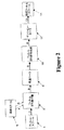
特に医療用途における呼吸補助では、気体は、導管を通して供給され、戻される。こうした導管は、患者にとって最高の快適さを保証するように、軽く、柔軟性があることが理想である。従来技術では、らせん状又は環状の補強リブを含む薄肉の導管が知られており、この補強リブは、圧搾及び狭窄に対するより大きな抵抗力を導管に与える役割を果たしながらも、導管を軽く、柔軟性のあるものにすることを可能にする。こうした導管の一例を図1に示す。 In respiratory assistance, particularly in medical applications, gas is supplied and returned through a conduit. Ideally, these conduits should be light and flexible to ensure maximum comfort for the patient. The prior art knows thin-walled conduits that include helical or annular reinforcing ribs that serve to provide the conduit with greater resistance to squeezing and stenosis while making the conduit light and flexible. It makes it possible to make something sexual. An example of such a conduit is shown in FIG.
この種類の導管を連続行程で製造することが都合がよい。従来技術においては、これは、薄いポリマー・テープを、隣接する層の縁部が僅かに重なるように、らせん状に成形具に巻き付けることによって達成されている。次いで、重なっている縁部の上面全体に溶融高分子のビードを付けて、縁部同士を融着し、同時にらせん状の補強リブを形成する。加熱導管を形成するためには、テープを成形具の上に引き出すときに、1つ又は2以上のヒータ・ワイヤがポリマー・テープ又はフィルム上に位置決めされる。このワイヤは、次の巻きによって覆われ、次いで溶融ビードによって覆われるように、テープの自由縁部に隣接して正確に位置決めされなければならない。連続的に正確な位置決めを行うことが難しい場合があり、位置決めがうまくいかない場合には、ワイヤは、導管壁に封入されずに管の内側又は外側のいずれかに露出する可能性がある。 It is convenient to produce this type of conduit in a continuous stroke. In the prior art, this is accomplished by winding a thin polymer tape around the forming tool in a spiral so that the edges of adjacent layers overlap slightly. Next, a bead of molten polymer is attached to the entire upper surface of the overlapping edges, and the edges are fused together to form a helical reinforcing rib. To form the heating conduit, one or more heater wires are positioned on the polymer tape or film as the tape is drawn over the forming tool. This wire must be accurately positioned adjacent to the free edge of the tape so that it is covered by the next turn and then covered by the melt bead. Continuous accurate positioning can be difficult and if positioning is unsuccessful, the wire can be exposed either inside or outside the tube without being encapsulated in the conduit wall.
本発明の目的は、特に呼吸回路のリムに利用され、上記を改善するのに少なくとも多少は役立ち、公衆及び医療従事者に有用な選択肢を少なくとも与えることになる導管を提供し、及び/又は、公衆及び製造者に有用な選択肢を与えるのに少なくとも多少は役立つ導管を製造する方法を提供することである。 The object of the present invention is to provide a conduit that is particularly utilized in the limb of the breathing circuit and that will at least somewhat help to improve the above and will at least provide a useful option for the public and healthcare workers, and / or It is to provide a method of manufacturing a conduit that is at least somewhat useful to give the public and manufacturers useful options.
本発明の第一の態様は、概略的には、導管を連続的に形成する方法であって、
薄いポリマーのリボンを準備するステップと、
少なくとも1つの導体を、該リボンに隣接して、該リボンとほぼ平行に位置決めするステップと、
該リボンを、該少なくとも1つの導体が折り曲げ部に隣接し、該折り曲げ部の中に封入されるように、該リボンと平行にほぼ半分に折り曲げるステップと、
該少なくとも1つの導体を永久的に封入するように、該折り曲げたリボンを熱溶接するステップと、
該折り曲げたリボンを、前記折り曲げたリボンの各々の一巻きの前縁部が成形具上で前記折り曲げたリボンの前の一巻きの後縁部の上に重なり、各々の一巻きの後縁部が次の一巻きの前縁部の下に重なるように、導管を回転させ前進させる該成形具の周囲にらせん状に供給するステップと、
溶融プラスチック材料のビードを、該ビードが隣接する縁部を溶接するように、前記折り曲げたリボンの隣接する一巻きの前記重なった縁部につけるステップとを備えている、
方法である。
A first aspect of the present invention is generally a method for continuously forming a conduit, comprising:
Preparing a thin polymer ribbon;
Positioning at least one conductor adjacent to and substantially parallel to the ribbon;
Folding the ribbon substantially in half parallel to the ribbon such that the at least one conductor is adjacent to and encapsulated in the fold;
Heat welding the folded ribbon to permanently encapsulate the at least one conductor;
The folded ribbon, the bent one turn of the front edge of each ribbon overlies the trailing edge of one turn before the folded ribbon on former, one turn of the trailing edge of each Spirally feeding around the forming tool to rotate and advance the conduit so that it overlaps under the leading edge of the next roll;
Applying a bead of molten plastic material to adjacent overlapping edges of the folded ribbon such that the bead welds adjacent edges;
Is the method.
好ましくは、少なくとも1つの導体は1対の導体であり、該1対の導体は平行にかつ狭い間隔で位置決めされ、リボンは1つの該導体の近傍で折り曲げられ、その結果、該1対の導体のうちの第1の導体が、折り曲げ部に隣接し、該折り曲げ部の中に封入され、該1対の導体のうちの第2の導体が、該第1の導体から間隔をおいて配置され、該折り曲げ部の中に封入されるようになる。
好ましくは、熱溶接するステップは、折り曲げたリボンを、該折り曲げたリボンを一緒に押しつけるように圧力をかける1対の加熱ローラの間に通すステップを含む。
好ましくは、ローラの少なくとも1つは、少なくとも1つの導体と該少なくとも1つの導体を覆うリボンの層との各々を少なくとも部分的に受け入れるための溝を含む。
好ましくは、本方法は、折り曲げたリボンに沿ってほぼ中間の位置に、該リボンとほぼ平行な折り目を形成するステップをさらに含む方法であって、熱溶接を行った後の該リボンが柔らかいうちに、該折り目を形成するものである。
好ましくは、折り目は、折り曲げフィルムを、該折り目の形状に応じて形作られた、少なくとも1組の折り目形成ローラの折り目形成領域を通過させることによって形成される。
Preferably, the at least one conductor is a pair of conductors, the pair of conductors are positioned in parallel and closely spaced, and the ribbon is folded in the vicinity of the one conductor so that the pair of conductors A first conductor is adjacent to and encapsulated in the fold, and a second conductor of the pair of conductors is spaced from the first conductor. , And is enclosed in the bent portion.
Preferably, the heat welding step includes passing the folded ribbon between a pair of heated rollers that apply pressure to press the folded ribbon together.
Preferably, at least one of the rollers includes a groove for at least partially receiving each of the at least one conductor and the layer of ribbon covering the at least one conductor.
Preferably, the method further comprises the step of forming a crease substantially parallel to the ribbon at a substantially intermediate position along the folded ribbon, wherein the ribbon after thermal welding is soft. In addition, the fold is formed.
Preferably, the crease is formed by passing the fold film through a crease forming region of at least one set of crease forming rollers formed according to the shape of the crease .
本発明の他の態様は、概略的には、導管を連続的に形成する方法であって、
薄いポリマーのリボンを準備するステップと、
該リボンを加熱して柔らかくするステップと、
該リボンを横切る概ね中間の位置に該リボンとほぼ平行な折り目を形成するステップと、
前記折り目を付けたリボンを、前記折り目を付けたリボンの各々の一巻きの前縁部が成形具上で前記折り目を付けたリボンの前の一巻きの後縁部の上に重なり、各々の一巻きの後縁部が次の一巻きの前縁部の下に重なるように、導管を回転させ前進させる該成形具の周囲にらせん状に供給するステップと、
溶融プラスチック材料のビードを、該ビードが隣接する縁部を溶接するように、前記折り目を付けたリボンの隣接する一巻きの該重なった縁部につけるステップと備えている、方法である。
Another aspect of the invention is generally a method of continuously forming a conduit, comprising:
Preparing a thin polymer ribbon;
Heating the ribbon to soften;
Forming a crease substantially parallel to the ribbon at a generally intermediate position across the ribbon;
The ribbon with the fold line overlies the trailing edge of one turn before the ribbon leading edge of one turn of each ribbon with the fold line gave the crease on the former, each Spirally feeding around the forming tool to rotate and advance the conduit so that the trailing edge of one roll overlaps the leading edge of the next winding;
Applying a bead of molten plastic material to adjacent overlapping edges of the creased ribbon such that the bead welds adjacent edges.
好ましくは、折り目は、折り曲げフィルムを、折り目の形状に応じて形作られた少なくとも1組の折り目形成ローラの折り目形成領域を通過させることによって形成される。 Preferably, the crease is formed by passing the fold film through a crease forming region of at least one pair of crease forming rollers formed according to the shape of the crease .
本発明の他の態様は、概略的には、導管を連続的に形成するための装置であって、
薄いポリマーのリボンを供給するための手段と、
該リボンに隣接する、該リボンとほぼ平行な第1の位置に、少なくとも1つの薄い導体を供給するための少なくとも1つのスプールと、
該リボンを、該少なくとも1つの導体が折り曲げたリボンに隣接し、該折り曲げたリボンによって封入されるように、ほぼ半分に折り曲げる折り曲げ手段と、
該折り曲げフィルムを溶接し、該少なくとも1つの導体を永久的に封入するのに適した熱溶接手段と、
該折り曲げたリボンを、前記折り曲げたリボンの各々の一巻きの前縁部が成形具上で前記折り曲げたリボンの前の一巻きの後縁部の上に重なり、各々の一巻きの後縁部が次の一巻きの前縁部の下に重なるように、導管を回転させ前進させる該成形具の周囲にらせん状に供給するための手段と、
溶融プラスチック材料のビードを、該ビードが隣接する縁部を溶接するように、前記折り曲げたリボンの隣接する一巻きの該重なった縁部につける手段と、を備えている、
装置である。
Another aspect of the invention is generally an apparatus for continuously forming a conduit, comprising:
Means for supplying a thin polymer ribbon;
At least one spool for supplying at least one thin conductor to a first position adjacent to the ribbon and substantially parallel to the ribbon;
Folding means for folding the ribbon substantially in half so that the at least one conductor is adjacent to and folded by the folded ribbon;
Thermal welding means suitable for welding the folded film and permanently encapsulating the at least one conductor;
The folded ribbon, the bent one turn of the front edge of each ribbon overlies the trailing edge of one turn before the folded ribbon on former, one turn of the trailing edge of each Means for spirally feeding around the forming tool to rotate and advance the conduit so that it overlaps the leading edge of the next roll;
Means for applying a bead of molten plastic material to adjacent overlapping edges of the folded ribbon such that the bead welds adjacent edges;
Device.
好ましくは、本装置は、折り曲げたリボンを横切る概ね中間の位置に折り目を形成するための折り目形成手段をさらに含む装置であって、
該折り目は、該リボンとほぼ平行であり、
該折り目形成手段は、該成形具の周囲に供給される前に該リボンに折り目を付けるように位置決めされた、
ことを特徴とする。
Preferably, the apparatus further comprises a crease forming means for forming a crease at a generally intermediate position across the folded ribbon,
The fold is substantially parallel to the ribbon;
The crease forming means is positioned to crease the ribbon before being fed around the forming tool;
It is characterized by that.
本発明の他の態様は、概略的には、導管を連続的に形成するための装置であって、
薄いポリマーのリボンを供給するための手段と、
該ポリマーのリボンを加熱するための加熱手段と、
該加熱手段によって加熱された後に、該リボンを横切る概ね中間の位置に該リボンとほぼ平行な折り目を形成するための折り目形成手段と、
前記折り目を付けたリボンを、前記折り目を付けたリボンの各々の一巻きの前縁部が成形具上で前記折り目を付けたリボンの前の一巻きの後縁部の上に重なり、各々の一巻きの後縁部が次の一巻きの前縁部の下に重なるように、導管を回転させ前進させる該成形具の周囲にらせん状に供給するための手段と、
溶融プラスチック材料のビードを、該ビードが隣接する縁部を溶接するように、前記折り目を付けたリボンの隣接する一巻きの該重なった縁部につける手段と、を備えている、
装置である。
Another aspect of the invention is generally an apparatus for continuously forming a conduit, comprising:
Means for supplying a thin polymer ribbon;
Heating means for heating the polymer ribbon;
A crease forming means for forming a crease substantially parallel to the ribbon at a substantially intermediate position across the ribbon after being heated by the heating means;
The ribbon with the fold line overlies the trailing edge of one turn before the ribbon leading edge of one turn of each ribbon with the fold line gave the crease on the former, each Means for spirally feeding around the tool to rotate and advance the conduit so that the trailing edge of one roll overlaps the leading edge of the next winding;
Means for applying a bead of molten plastic material to adjacent overlapping edges of the creased ribbon such that the bead welds adjacent edges;
Device.
本発明の他の態様は、概略的には、上記のうちのいずれか1つに係る方法によって形成される導管である。 Another aspect of the invention is generally a conduit formed by a method according to any one of the above.
本発明に関する技術分野の当業者であれば、添付の特許請求の範囲に記載された本発明の範囲から逸脱することなく、本発明の構成における多くの変更、並びに、本発明の多様な実施形態及び用途を想起できる。本明細書の開示及び記載は、単なる例示であり、いかなる意味においても限定的であることを意図するものではない。 Those skilled in the art to which the present invention pertains will perceive many changes in the structure of the present invention and various embodiments of the present invention without departing from the scope of the present invention as set forth in the appended claims. And you can recall the use. The disclosures and the descriptions herein are merely exemplary and are not intended to be in any sense limiting.
本発明は、概略的には、呼吸導管に関し、特に、薄いフィルムをらせん状に巻いた導管を形成する改善された方法に関する。したがって、本発明は、(水蒸気を透過することが可能な)通気性材料及び/又は非通気性材料を含む様々な材料から製造される呼吸導管に適用できることが分かる。 The present invention relates generally to respiratory conduits and, more particularly, to an improved method of forming a spirally wound thin film. Thus, it can be seen that the present invention is applicable to respiratory conduits made from a variety of materials, including breathable materials (which are permeable to water vapor) and / or non-breathable materials.
閉塞型睡眠時無呼吸症候群(OSA)に罹っている患者に陽圧気体を供給する持続的気道陽圧法(CPAP)システム又は陽圧換気システムは、説明した従来技術と同様の導管を用いることが多い。補助呼吸を用いるこれらの用途及び他の医療用途の多くでは、高レベルの相対湿度を有する気体が、比較的制約された大きさの導管を通して患者に供給され、場合によっては戻される。本発明の目的は、高頻度の使用による応力に耐える代替的な導管、すなわち、柔軟性はあるが軸方向の引っ張り又は動きの下で破損しにくい代替的な導管を提供することである。 A continuous positive airway pressure (CPAP) system or positive pressure ventilation system that supplies positive pressure gas to a patient suffering from obstructive sleep apnea syndrome (OSA) may use a conduit similar to the prior art described. Many. In many of these applications and other medical applications that use assisted breathing, a gas having a high level of relative humidity is supplied to the patient and possibly returned through a relatively constrained sized conduit. It is an object of the present invention to provide an alternative conduit that can withstand the stresses of frequent use, i.e., an alternative conduit that is flexible but resistant to breakage under axial pulling or movement.
本発明の好ましい導管は、均質なフラット・フィルムに形成されたポリマー・プラスチックのブロックといった、非通気性材料から形成される。こうしたポリマー材料の例は、EXACT及びEVOLUEというブランドで販売されるものである。
本発明の導管の代替的な形態においては、均質なフラット・フィルムに形成された親水性ポリエステル・ブロック共重合体といった通気性材料から導管を形成することができる。
Preferred conduits of the present invention are formed from a non-breathable material, such as a polymer plastic block formed into a homogeneous flat film. Examples of such polymeric materials are those sold under the brands EXACT and EVOLUE.
In an alternative form of the conduit of the present invention, the conduit can be formed from a breathable material such as a hydrophilic polyester block copolymer formed into a homogeneous flat film.
以下の実施形態は、EVOLUEなどの材料による例示的な非通気性の薄いフィルム壁構造を特に参照して説明されることになる。しかしながら、以下に説明される実施形態においては、導管壁を形成するのに用いられる材料は、通気性又は非通気性のいずれかとすることができ、通気性材料と非通気性材料の両方の組み合わせを含むこともできることがわかる。また、以下に説明される実施形態について、本発明の方法における予備成形段階の際に扱われるフィルムは、初めにスプール上に巻かれた予備成形フィルムとして供給するか、又は代替的に、押し出し成形機から直接供給することができることがわかる。さらに、当業者であれば、導管の製造に用いられる成形具に供給される材料は、フィルムを正確に位置決めし、必要な張力を与えるために、ガイド及び/又はローラを必要とする場合があることがわかる。 The following embodiments will be described with particular reference to an exemplary non-breathable thin film wall structure with materials such as EVOLUE. However, in the embodiments described below, the material used to form the conduit wall can be either breathable or non-breathable, and a combination of both breathable and non-breathable materials. It can be seen that can also be included. Also, for the embodiments described below, the film treated during the preforming step in the method of the present invention is supplied as a preformed film initially wound on a spool or, alternatively, extruded. It can be seen that it can be supplied directly from the machine. Furthermore, those skilled in the art may require that the material supplied to the forming tool used to manufacture the conduits require guides and / or rollers to accurately position the film and provide the necessary tension. I understand that.
導管壁は比較的、薄い壁厚を有するように製造されることが好ましく、そのため、導管壁の膜は、自立するのに十分なほどには丈夫ではない場合がある。したがって、支持するために、らせん状補強部材又はヘリカル補強部材が管状壁膜の一部として設けられる。ヘリカル支持部材又はらせん状支持部材は、ポリマー・プラスチック材料から形成され、導管の壁に用いられるものと同じ材料とするか、又は他の適合性のあるプラスチック材料のいずれかとすることができる。
図1を参照すると、当該技術分野で知られている柔軟性のある呼吸導管のレイアップ構成が示される。
The conduit wall is preferably manufactured to have a relatively thin wall thickness so that the membrane of the conduit wall may not be strong enough to be self-supporting. Thus, for support, a helical reinforcing member or a helical reinforcing member is provided as part of the tubular wall membrane. The helical support member or helical support member is formed from a polymer plastic material and can be the same material used for the wall of the conduit or any other compatible plastic material.
Referring to FIG. 1, a flexible breathing conduit layup configuration known in the art is shown.
フィルムの予備形成
本発明の導管を製造する際の第1のステップは、折り曲げたプラスチック・フィルムの形成である。フィルムは、少なくとも1つの一体的な導体と共に、又は導体無しで、形成することができる。予備成形フィルムの他の形態においては、フィルムは、1つ又は複数の導体の代わりに、発泡ストリップ、導電性フィルム又は他の導電性材料若しくは絶縁性材料のストリップ、あるいは、両方の組み合わせといった、他の材料と共に形成することができる。以下では、一例として、折り曲げたプラスチック・フィルムの1つのこうした形態、すなわち、少なくとも1つの一体的に形成された導体を用いる形態のみを説明する。
Film Preform The first step in making the conduit of the present invention is the formation of a folded plastic film. The film can be formed with or without at least one integral conductor. In other forms of preformed film, the film may be other than one or more conductors, such as foam strips, conductive films or other conductive or insulating material strips, or a combination of both. It can be formed together with other materials. In the following, as an example, only one such form of a folded plastic film, i.e. using at least one integrally formed conductor, will be described.
図2を参照すると、2つの平行な導体を含むプラスチックを形成する方法が示される。最初に、EVOLUEフィルムなどのプラスチック・フィルム2が、スプール1上に供給される。2つの導電性ワイヤ4、5が、2つのスプール6上に供給される。フィルム2及びワイヤ4、5は、それぞれのスプール1、6から同時に引き出され、フィルム折り曲げ機3に送り込まれる。フィルム折り曲げ機3は、好ましくは、フィルム2の中心の折り曲げ部(図3から図6までのX)を移動しながら、フィルム2を2つのワイヤの一方5と共に半分に折り曲げる。図3は、フィルム折り曲げ機に送り込まれる前のフィルム2及び2つのワイヤ4、5を示す。ワイヤ4、5は、折り位置Xに隣接するガイドによって正確に位置決めされ、フィルム2の表面上に間隔をあけて配置される。図3において7で表示される矢印は、フィルム2の第2の側16上に折り曲げてワイヤ4、5を封入する、フィルムの一方の側(第1の側15)を示す。その結果として得られる、ほぼ平行な2つの封入された導体を含む二層折り曲げフィルム8が、図4に示される。第1の側方半分15はフィルム8の上層になり、第2の側方半分16はフィルム8の下層になる。
Referring to FIG. 2, a method of forming a plastic that includes two parallel conductors is shown. Initially, a
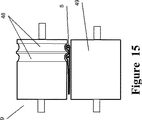
図2、図4、及び図15を参照すると、次いで、完成したワイヤ4、5封入折り曲げフィルム8(折り曲げられたフィルム)は、2つの高温ローラ9の間に引き出される。高温ローラは、フィルムを軟化させ、加圧によって隣接層を接合するのに十分な表面温度、例えば約90℃及び120℃の表面温度を有する。フィルムが高温ローラ9の間を移動する速度に応じて、いくつかの段階の高温ローラを設け確実に適切な溶接が行われるようにすることが必要な場合がある。さらに、超音波溶接又は熱風溶接などの二次溶接処理を含むことが望ましいこともある。高温ローラは、例えばアルミニウムといったいずれかの適切な材料で形成することができる。高温ローラの少なくとも1つの変形可能な外側表面層49は、ローラを通過するフィルムを把持するのに役立ち、封入されたワイヤの周囲でローラ表面の少なくとも1つが僅かに変形することを可能にするということが分かった。ローラ上のこの外側層についての適切な材料の一例は、シリコン・ゴムである。高温ローラ9は、モータ(図示せず)によって駆動され、フィルム2及びワイヤ4、5をそれぞれのスプール1、6から引っ張り、フィルム折り曲げ機3を通してフィルム2を引き出す。ローラ9からの熱がフィルムを軟化させると同時に、折り曲げフィルムがローラの間を通過したときにローラによってかけられる圧力が、折り曲げフィルムの層15及び16をまとめて加圧し、折り曲げられた側を溶融させ、ワイヤを永久的にその中に封入する。
Referring to FIGS. 2, 4, and 15, the completed
封入されたワイヤ4、5が、溶融処理の間にその所望の位置に維持されることを確実にするために、高温ローラの少なくとも1つは、ワイヤ4、5を受け入れるのに適した1組の溝48を含む。溝の位置及び寸法は、ローラがフィルムにかける圧力によって導電性ワイヤ4、5の領域でフィルムが平らになることを防止し、したがって、封入されたワイヤ周囲のポリマー・フィルムの望ましくない薄化を減少させるようなものである。これらの溝48は、ワイヤを案内し、ワイヤ4、5が折り曲げ部に対して正確に位置決めされ、所望の距離、例えば約1ミリメートルの間隔をあけて配置されることを確実にする。折り曲げフィルム8の製造においては、フィルム折り曲げ機3を折り曲げ部Xが高温ローラ9の溝の1つの上を動くように位置決めし、それにより第1のワイヤ5を折り曲げ部Xの中に位置決めし、第2のワイヤ4を折り曲げ部Xから1ミリメートル離すようにすることが好ましい。フィルム折り曲げ機3は、不均一なフィルムの重なりを避けるように構成される。フィルム折り曲げ機3のこうした位置決めは、予備成形され、折り曲げられた良質のフィルムを生産するためには重要である。予備成形され、折り曲げフィルムの他の実施形態においては、ワイヤは、折り曲げ部からある距離を置いて、又は、互いに異なる距離に、配置することができる。
To ensure that the encapsulated
次いで、折り曲げフィルムは、高温ローラ9から引き出され、好ましくは、図14に示されるようなフィルム折り目形成機10を通過させられる。フィルム折り目形成機10は、ローラ34の対応するように形作られた溝の中を通る、ほぼV字型の縁部を有するローラ33から構成される。フィルム折り目形成機10は、図5に示されるように、折り曲げフィルム8に折り目12を形成する。折り目12は、高温ローラ9に続いて折り曲げフィルム8に形成されるが、フィルムは依然として柔らかい。折り目12は、完成した導管における補強ビードの巻きの間の概ね中間に折り目を位置決めするために、折り曲げフィルムの幅に沿って概ね中間に形成することになる。次いで、折り曲げて折り目を付けたフィルム13は、完成フィルムのスプール14上に均一に引き出される。折り目12の目的は、導管壁をヘリカル補強ビードの間で外側に偏らせることである。使用中に導管が収縮するか又は曲がったときには、導管内部の気体流との干渉を減少させるように、ビードの間の導管壁部分を外側に膨らませることが望ましい。折り目12は、導管が収縮するか又は曲がったときに、補強ビードの間の導管壁部分が補強ビード19の間で決まった折り位置をとるように促す。
The folded film is then drawn from the
ここで、図2及び図11を参照する。折り曲げフィルムは、フィルム折り目形成機10から出て来たときも依然として柔らかいので、折り曲げフィルム8の張力は、折り曲げフィルム8が伸び過ぎてフィルムをより薄く又はより狭くすることがないように正確に制御されなければならない。したがって、フィルム8は、少なくとも1つのテンション・ローラ11を通して引き出すことができるが、2つ以上のローラを用いることもできる。図11に示されるように、2つのテンション・ローラ40、41は、アーム42に取り付けて設けられ、位置センサ43によって制御される。ローラ40、41が、フィルム8に正確な張力を与えるような位置にない場合には、ローラ40、41は、正確なフィルム張力が加えられるまで調整される。ローラ40、41は、回転軸44の周りに回転するアーム42に取り付けられる。フィルム8の張力が増加して、ローラ40、41及びアーム42にさらに力がかかると、アーム42は、(図11に示される)中立位置から上方に動く。アーム42の近くに配置された位置センサ43は、アームの動きを検出し、ローラを通してフィルムを完成フィルムのスプール14上に引き出すモータの速度を減少させ、その結果、テンション・ローラ40、41を通るフィルム8の引っ張る力を減少させる。反対に、位置センサ43が、フィルム張力の減少によってアーム42が中立位置から下方に動いたことを検出した場合には、センサ43は、モータの速度を増加させ、フィルム8がローラ40、41を通してより速く引き出されるようにする。
Reference is now made to FIGS. Since the folded film is still soft when it comes out of the film
(図5に示されるような)折り目12の形状を変化させることが、導管壁を望ましい方法でたわませるために有利な場合があることが分かった。例えば、(図6に示されるような)より幅広く、より丸みのある弓形の折り目は、導管が軸方向に収縮するか又は曲がったときに導管壁が望みどおりの挙動を示すことを確実にするという点で、より効果的なものとなる可能性があることが分かった。当業者であれば、(図14に示されるような)折り目形成ローラ33及びそれに対応するローラ34の形が、折り目12の形状を左右することがわかる。さらに、折り目形成時にフィルムが望ましくない方法で丸まる傾向を減らすように、折り目形成ローラ33を、図示されたものより幅広くして、折り曲げフィルム8の外側領域を案内するための部分を含むこともできる。また、フィルムが折り曲げられ、溶融された後ではあるが、予備成形され、折り曲げフィルムが保管スプール14に巻かれる前に折り目12を形成することによって、保管スプール14上にある間にある程度の折り目12の平坦化が生じることが分かった。折り目形成処理を、導管を形成する直前まで遅らせることが有利であることが分かった。本方法のこの代替的な実施形態においては、予備成形テープ8は、保管スプールに巻かれる前であって十分に冷却された後に、(封入された導体と共に、又は導体無しで)折り曲げられ、溶融される。図16を参照すると、折り曲げフィルム8(しかし、折り目は未形成)は、後述される導管形成処理が開始する前に、加熱され、上述のフィルム折り目形成機10を通して供給される。テープ形成及び巻き取り処理を制御するために、上述と同様の方法で、フィルムを、一連のテンション・ローラ及び/又はピンチ・ローラを通過させることができる。フィルムがフィルム折り目形成機10を通過した後、フィルムは、形成マンドレル24上に供給されて導管17が形成される前に、冷却され、僅かに固くされる。本発明の予備成形フィルムの他の実施形態においては、フィルムは、導電性ワイヤを内部に封入させずに形成することができる。フィルムのこの形態は、加熱要素を必要としない導管に用いることができる。
It has been found that changing the shape of the crease 12 (as shown in FIG. 5) may be advantageous to deflect the conduit wall in the desired manner. For example, a wider, more rounded arcuate fold (as shown in FIG. 6) ensures that the conduit wall behaves as desired when the conduit is axially contracted or bent. In this regard, it has been found that there is a possibility of becoming more effective. Those skilled in the art will recognize that the shape of the crease forming roller 33 (as shown in FIG. 14) and the corresponding
ここで説明される導管を形成する方法は、導体又は絶縁体といった1つ又は2以上の要素を封入する、予備成形され、折り曲げられたテープと、予備成形されたテープを形成マンドレルに供給する前のいずれかにおいて予備成形されたテープに折り目を付ける方法とを開示している。しかしながら、フィルムを予備成形する方法及びあらかじめ折り目を形成する方法は、導管形成方法にいずれも適用するか、又は個々に適用することができる。 The method of forming a conduit described herein includes a preformed and folded tape that encapsulates one or more elements, such as conductors or insulators, and prior to feeding the preformed tape to a forming mandrel. And crease a preformed tape in any of the above. However, the method of preforming the film and the method of forming the folds in advance can be applied to the conduit forming method or can be applied individually.
導管形成
次に、上述のような予備成形フィルムを用いて形成される導管を、より詳細に説明する。(少なくとも1つの導体を含む)加熱導管の製造は、少なくとも1つの埋め込み導体を含む上述のような予備成形フィルムを用いることによって達成されることがわかる。同様に、非加熱導管の製造は、封入された導体を持たない予備成形フィルムを使用することによって達成される。
Conduit Formation Next, the conduit formed using the preformed film as described above will be described in more detail. It can be seen that the manufacture of the heating conduit (including at least one conductor) is accomplished by using a preformed film as described above that includes at least one embedded conductor. Similarly, the manufacture of unheated conduit is accomplished by using a preformed film that does not have an encapsulated conductor.
以下の説明は、封入された材料を持つ予備成形フィルムと、封入された材料を持たない予備成形フィルムとを区別しない。したがって、以下で「フィルム」又は「予備成形されたフィルム」と言うときは、フィルムは、埋め込み導体若しくは絶縁材料又はその両方を含む場合も含まない場合もある。 The following description does not distinguish between preformed films with encapsulated material and preformed films without encapsulated material. Thus, when referred to below as “film” or “pre-formed film”, the film may or may not include embedded conductors and / or insulating materials.
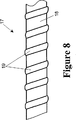
図8は、上述のフィルムから、以下に説明される導管形成方法を用いて形成された導管17を示す。図(例えば図7)は、例示的なものであり、完成製品には実際に存在しないが層を区別するために図に示される、フィルムの層と補強ビードとの間の隙間又は間隙を示している。導管は、気体を患者に供給するための搬送路又は通路として用いることができ、薄いフィルムの柔軟壁を有する。上述の予備成形フィルムなどのフィルムは、隣接する層の縁部分が重なるようにらせん状又はヘリカルに並べられ、導管又はチューブ17の壁18を形成する。ポリマー材料のヘリカル補強ビード19は、フィルムの隣接する一巻きの重なり部分の上に押し出され、フィルムの重なり部分を接合し、連続的な導管又はチューブ17を形成する。
FIG. 8 shows a
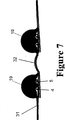
図7は、図8の導管と同様の導管を示すが、導管壁内に形成された一体的な導体を有するものである。図7は、封入された2つの導電性ワイヤ4、5を含む折り曲げフィルムの断面を示す。ビード19は、(封入された導電性ワイヤ4、5を有する)隣接する層31、32の重なり部分の上に押し出される。溶融ビード19は、2つの層を互いに接合する。
FIG. 7 shows a conduit similar to that of FIG. 8, but with an integral conductor formed in the conduit wall. FIG. 7 shows a cross section of a folded film comprising two encapsulated
図7又は図8の導管を製造するのに適した形成装置の例が、図9及び図12に示される。図10は、本発明の導管形成処理におけるステップを示す。上述の予備成形フィルムのスプール14は、導管形成装置のフレーム(図示せず)に取り付けられる。(ワイヤ4、5を含むことがある)フィルムは、スプール14から、種々のテンション・パッド及びローラ21を通し、次いでピンチ・ローラ22を通して引き出される。次に、フィルムは、少なくとも1つのテンション・ローラ23を通過し、マンドレル又は成形具24に供給される。
An example of a forming apparatus suitable for manufacturing the conduit of FIG. 7 or FIG. 8 is shown in FIGS. FIG. 10 illustrates the steps in the conduit formation process of the present invention. The preformed
図9を参照すると、既知の種類のものであることが好ましい成形具は、中心の支持ロッドの周囲に配置された複数の回転ロッド又はケーブルを含む。ロッド又はケーブルは、機械台26内部のギアボックスから延び、ギアボックスによって回転させられる。少なくとも導管形成領域においては、回転ロッドは、らせん状の経路をたどる。支持ロッドに対するこのロッドのピッチ角は、形成される導管のピッチ角を決める。こうした成形具の例が、イタリアのOLMAS SRLから入手可能ならせん状パイプライン・マンドレルである。
Referring to FIG. 9, a forming tool, preferably of a known type, includes a plurality of rotating rods or cables disposed around a central support rod. The rod or cable extends from the gearbox inside the
成形具上に形成されている導管は、回転ケーブルの動きによって回転させられ、矢印27の方向に進められる。成形具の前進速度は、ケーブルの回転速度に対して選択され、成形具上のフィルムのらせん状巻き付けピッチによって決まり、その結果フィルムの隣接する巻きはわずかに重なるようになる。上述の予備成形フィルム8のスプール14は、最終的に、成形具の動作によって(テンション・ローラなどを通して送り込まれた後に)成形具(マンドレル24)上にらせん状に供給される。フィルム8のらせん状配置のピッチは、フィルム8の幅と比べて僅かに小さく、約2ミリメートルの重なりを生じさせる。フィルム8のらせん状配置は、図8に示される導管壁18を形成する。押し出し機28は、ポリマー材料のビード19をフィルムの巻きの重なり上に押し出す。回転マンドレル24は、フィルム8の層に溶接するために十分に加熱された溶融ビード19を、フィルム8の隣接する巻きの重なり部分を覆うように引き出す。本発明の1つの好ましい実施形態においては、ビード19は、フィルムの層同士を熱結合するのに十分な熱を与える約250℃で押し出される。この方法によって形成される導管の内径は、約19ミリメートルである。当業者であれば、例えば超音波溶接又は熱風溶接といった代替的な又は二次的な溶接処理を利用することもできるがわかる。
The conduit formed on the forming tool is rotated by the movement of the rotating cable and advanced in the direction of
しかしながら、本形成方法は、より太い導管とより細い導管のいずれにも適している。導管が、封入された導電性ワイヤ(図7を見よ)を有する加熱型である場合には、ビード19が正しい位置に引き出され、重なったフィルム同士を完全に接合し、ワイヤを封入するように、押し出し機28を位置決めする。加熱導管及び非加熱導管のいずれの場合にも、ビード19は、導管を形成するのに役立つような形状にされる。
However, the forming method is suitable for both thicker and thinner conduits. If the conduit is of the heated type with an encapsulated conductive wire (see FIG. 7), the
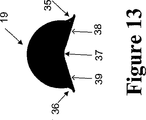
図7及び図13を参照すると、ビード19はその下面の中央付近が凹形であり、縁部38、39は、ビード19の周辺部にかけて角度が設けられる。凹形の下面37は、ビード19を置くための案内となる役目を果たす。ビードは、封入されたワイヤによって作り出されるフィルムの突出部分をなぞろうとする。ビードの下面のまっすぐな面は、フィルム20を平らに保つのにも役立ち、形成処理の間にほぼ水平になる。ビード19は、ビードの基部方向に意図的な縁部35、36を設けた状態で押し出すことができる。押し出された後、ビード19は、形状が変化する、すなわち膨らもうとする。凹みをつけられた縁部35、36は、仕上げ導管における補強ビード19の最終的な形状をより良好に制御するために設けることができる。
Referring to FIGS. 7 and 13, the
このようにして形成された導管が縦方向に収縮したときは、図5及び図6に関して示され説明されたような、フィルムに形成された折り目12は、補強ビード19の間で導管を外側に折り曲げさせようとし、導管を通る気体通路から外側へフィルムを移動させる。ビードの幅及び高さは、その全体形状及び大きさを維持しながら、適切な破壊強度を与え、ビードの間でフィルムが上方に折れ曲がるのに十分な空間を許容するように選択される。
When the conduit formed in this way contracts in the longitudinal direction, the
図10及び図12を再び参照すると、本発明の導管形成装置のフレームは、フィルムがマンドレル24上に送り込まれる角度を調節することができるように、多くの自由度を有する。フレームは、フレームに取り付けられた1組のピンチ・ローラ22のセットを含み、ピンチ・ローラは、フィルムを、フィルムのスプール14から、少なくとも1つのテンション・パッドと、同じく導管形成装置のフレームに取り付けられた少なくとも1つのローラ21の周囲とを通して引っ張る。次いで、フィルム20は、少なくとも1つのテンション・ローラ23の周囲に供給され、次に、マンドレル24上に供給される。
Referring again to FIGS. 10 and 12, the conduit forming device frame of the present invention has many degrees of freedom so that the angle at which the film is fed onto the
ピンチ・ローラ22とマンドレル24上のケーブルとの間の速度差が、フィルムに張力を与えることになる。フィルム張力は、マンドレル24上のフィルムの安定性を維持し、導管が曲がるか又は収縮したときにフィルム壁が補強ビード19の間で上方に折れ曲がることを可能にするためにも重要である。
The speed difference between the
テンション・ローラ23は、フィルムの予備成形方法について前述したものと同様に、センサ45及びアーム46によって制御される。フィルム20の張力が増加した場合には、(アーム46に取り付けられた)ローラ23と、回転軸47の周りに回転するアーム46とが、矢印Aの方向である上方に動く。位置センサ45がアーム46したがってローラ23の位置の変化を検出し、ピンチ・ローラ22を駆動するモータが、フィルムがスプール14から引き出される速度を増加させ、フィルムにかかる張力を減らして、ローラ23及びアーム46を図12に示される中央位置に戻す。反対に、フィルムの張力が減少した場合には、アーム46及びローラ23は、矢印Bの方向である下方に動く。位置センサ45は、この位置変化を検出し、ピンチ・ローラ22を駆動するモータの、フィルムがスプール14から引き出される速度を減少させる。センサ45、回転可能なアーム46、及びローラ23は、マンドレル24上に巻かれているフィルム20が一定の重なりを有するように、フィルムの一定の張力を維持することを確実にする。
The
マンドレル24は、導管がマンドレル24上に形成されたときに、ビード19がフィルムの重なった層の両方を通して溶融しないことを確実にするように、導管を冷却する空冷若しくは水冷又はその両方を含むことができる。導管の外部に、さらなる冷却を設けることもできる。内部空冷は、管の内部にいくつかの細い空気ジェットを吹き付ける、マンドレル上のステンレス鋼の針状チューブによって行うことができる。外部空冷は、管の外側にブレード状の空気を吹き付ける一連の空気ジェットによって行うことができる。
The
ここでマンドレル24をより詳細に説明する。マンドレル24は、すべてが同じ速度で回転する6つのステンレス鋼ケーブルを含む。ケーブルは、ステンレス鋼マンドレルにらせん状に機械加工したマンドレル24のアンダーカット溝の内部に配置される。ステンレス鋼で作られることが好ましいマンドレル24は、フィルムがマンドレル24ではなくケーブル上に載るように隙間を設けるために、マンドレルのケーブル溝の間に機械加工された扇形の隙間を有する。空冷チューブ用の空間を設けるために、これらの扇形の隙間の中央にも溝が機械加工される。マンドレルは、水冷にして、十分に冷却されていることを確実にするように水流量の監視手段を含むこともできる。
The
ケーブルは、上述のように、フィルムをマンドレル24上に引っ張る駆動力を与える。これらのケーブルのらせん角度は、フィルムの正確な重なり量を作り出すのに重要である。ケーブルの角度を水平に対して6.6度に設定すると、フィルムは、マンドレル24上に引き出され、上述のようにらせん状にマンドレルの周囲に巻き付けられる。この設定角度によって、フィルムは約2ミリメートルだけ重なるようになる。
The cable provides a driving force that pulls the film onto the
図7を参照すると、ワイヤ4、5の下のフィルム層の重なりによって、ワイヤと導管内側との間にフィルムの3つの厚みが設けられる。これが、ワイヤが導管から溶け出して、導管の内部に露出することを防止し、ワイヤを保持するより厚い面に、より高い耐久性を与える。マンドレル上に供給されるフィルムの角度は、導管が特定のピッチを持つように形成されることを確実にし、このピッチが、破壊強度とビード間のフィルム量との間に良好な妥協点を与えることを見出した。
Referring to FIG. 7, the overlap of the film layers under the
本発明のフィルムを予備成形する方法は、当初のフィルムをさらに折り曲げて、より多くの層を持つフィルムを作るステップを含むように拡張することができる。あるいは、本発明の導管を形成する際に2つ以上のフィルムを用いて、導管壁の厚さすなわち壁強度は増加させるが、依然として柔軟性のある導管を提供することができる。 The method of preforming the film of the present invention can be expanded to include the step of further folding the original film to create a film with more layers. Alternatively, two or more films can be used in forming the conduit of the present invention to provide a conduit that is flexible while still increasing the thickness of the conduit wall, i.e., wall strength.
上述の方法によって形成される加熱導管は、導管内の凝縮の蓄積を減少させることができ、導管を通って流れる加湿気体の温度を維持する手段をも提供することができる。加熱導管は、一般に、持続的気道陽圧(CPAP)治療といった用途において、気体搬送路として用いられる。通路を通って流れる気体を加熱するための導電性ワイヤを通路が含むこうした導管では、少なくとも導管の一端における対応するコネクタは、電気エネルギーを導管の加熱ワイヤに供給するために、加湿気体源と接続するのに適した電気的接続部を含む。 The heated conduit formed by the above-described method can reduce the accumulation of condensation in the conduit and can also provide a means to maintain the temperature of the humidified gas flowing through the conduit. Heated conduits are commonly used as gas delivery paths in applications such as continuous positive airway pressure (CPAP) therapy. In such conduits where the passage includes a conductive wire for heating the gas flowing through the passage, at least a corresponding connector at one end of the conduit connects to a humidified gas source to supply electrical energy to the heating wire of the conduit. Including electrical connections suitable for
本発明の1つの態様によれば、埋め込み加熱ワイヤを備えるテープを予備成形することによって、ワイヤを管形成マンドレルに直接当てる場合と比べて容易に制御される処理において、ワイヤをテープ縁部に対して正確に配置するという利点がもたらされる。 In accordance with one aspect of the present invention, by pre-forming a tape with an embedded heating wire, the wire is against the tape edge in a process that is more easily controlled than when the wire is applied directly to the tube-forming mandrel. Provides the advantage of precise placement.
本発明の別の態様によれば、テープに折り目を付けることによって、導管壁の好ましい変形方式を定めるという利点がもたらされ、管壁は、その大部分が導管の曲がり又は収縮の際に外側に膨らまされるようになる。 In accordance with another aspect of the present invention, the crease in the tape provides the advantage of defining a preferred deformation mode of the conduit wall, the tube wall being largely external when the conduit is bent or contracted. Will be inflated.
Claims (12)
薄いポリマーのリボンを準備するステップと、
少なくとも1つの導体を、前記リボンに隣接して、該リボンとほぼ平行に位置決めするステップと、
前記リボンを、前記少なくとも1つの導体が折り曲げ部に隣接し、前記折り曲げ部の中に封入されるように、該リボンと平行にほぼ半分に折り曲げるステップと、
前記少なくとも1つの導体を永久的に封入するように、前記折り曲げたリボンを熱溶接するステップと、
前記折り曲げたリボンを、前記折り曲げたリボンの各々の一巻きの前縁部が成形具上で前記折り曲げたリボンの前の一巻きの後縁部の上に重なり、各々の一巻きの後縁部が次の一巻きの前縁部の下に重なるように、導管を回転させ前進させる前記成形具の周囲にらせん状に供給するステップと、
溶融プラスチック材料のビードを、前記ビードが隣接する縁部を溶接するように、前記折り曲げたリボンの隣接する一巻きの前記重なった縁部につけるステップとを備えている
ことを特徴とする方法。A method of continuously forming a conduit,
Preparing a thin polymer ribbon;
Positioning at least one conductor adjacent to and substantially parallel to the ribbon;
Folding the ribbon substantially in half parallel to the ribbon such that the at least one conductor is adjacent to and enclosed in the fold;
Heat welding the folded ribbon to permanently enclose the at least one conductor;
The folded ribbon is overlapped with the leading edge of each turn of the folded ribbon over the trailing edge of the wound before the folded ribbon on the forming tool, and the trailing edge of each wound. Spirally feeding around the former to rotate and advance the conduit so that is over the leading edge of the next roll;
Applying a bead of molten plastic material to adjacent overlapping turns of the folded ribbon so that the adjacent edges of the bead are welded.
請求項1に記載の方法。The at least one conductor is a pair of conductors, the pair of conductors are positioned in parallel and closely spaced, and the ribbon is folded in the vicinity of the one conductor so that the pair of conductors The first conductor is adjacent to the bent portion and enclosed in the bent portion, and the second conductor of the pair of conductors is disposed at a distance from the first conductor. , Comes to be enclosed in the bent portion,
The method of claim 1 .
請求項1又は請求項2に記載の方法。The thermal welding includes passing the folded ribbon between a pair of heated rollers that apply pressure to squeeze the folded ribbon together.
The method according to claim 1 or claim 2 .
請求項3に記載の方法。At least one of the rollers includes a groove for at least partially receiving each of the at least one conductor and a layer of ribbon covering the at least one conductor;
The method of claim 3 .
請求項1ないし4のいずれか1項に記載の方法。Forming a crease substantially parallel to the ribbon at a substantially intermediate position along the folded ribbon, and forming the fold while the ribbon after the thermal welding is soft;
5. A method according to any one of claims 1 to 4 .
請求項5に記載の方法。The crease is formed by passing the fold film through a crease forming region of at least one set of crease forming rollers formed according to the shape of the crease .
The method of claim 5 .
薄いポリマーのリボンを準備するステップと、
前記リボンを加熱して柔らかくするステップと、
前記リボンを横切る概ね中間の位置に該リボンとほぼ平行な折り目を形成するステップと、
前記折り目を付けたリボンを、前記折り目を付けたリボンの各々の一巻きの前縁部が成形具上で前記折り目を付けたリボンの前の一巻きの後縁部の上に重なり、各々の一巻きの後縁部が次の一巻きの前縁部の下に重なるように、導管を回転させ前進させる前記成形具の周囲にらせん状に供給するステップと、
溶融プラスチック材料のビードを、前記ビードが隣接する縁部を溶接するように、前記折り目を付けたリボンの隣接する一巻きの前記重なった縁部につけるステップと備えている、
ことを特徴とする方法。A method of continuously forming a conduit,
Preparing a thin polymer ribbon;
Heating the ribbon to soften;
Forming a fold generally parallel to the ribbon at a generally intermediate position across the ribbon;
The ribbon with the fold line overlies the trailing edge of one turn before the ribbon leading edge of one turn of each ribbon with the fold line gave the crease on the former, each Spirally feeding around the former to rotate and advance the conduit so that the trailing edge of one roll overlaps the leading edge of the next winding;
Applying a bead of molten plastic material to adjacent overlapping turns of the creased ribbon such that the bead welds adjacent edges;
A method characterized by that.
請求項7に記載の方法。The crease is formed by passing the fold film through a crease forming region of at least one set of crease forming rollers formed according to the shape of the crease .
The method of claim 7 .
薄いポリマーのリボンを供給するための手段と、
前記リボンに隣接する、該リボンとほぼ平行な第1の位置に、少なくとも1つの薄い導体を供給するための少なくとも1つのスプールと、
前記リボンを、前記少なくとも1つの導体が折り曲げたリボンに隣接し、前記折り曲げたリボンによって封入されるように、ほぼ半分に折り曲げる折り曲げ手段と、
前記折り曲げフィルムを溶接し、前記少なくとも1つの導体を永久的に封入するのに適した熱溶接手段と、
前記折り曲げたリボンを、前記折り曲げたリボンの各々の一巻きの前縁部が成形具上で前記折り曲げたリボンの前の一巻きの後縁部の上に重なり、各々の一巻きの後縁部が次の一巻きの前縁部の下に重なるように、導管を回転させ前進させる前記成形具の周囲にらせん状に供給するための手段と、
溶融プラスチック材料のビードを、前記ビードが隣接する縁部を溶接するように、前記折り曲げたリボンの隣接する一巻きの前記重なった縁部につける手段と、を備えている、
ことを特徴とする装置。An apparatus for continuously forming a conduit,
Means for supplying a thin polymer ribbon;
At least one spool for supplying at least one thin conductor to a first position adjacent to the ribbon and substantially parallel to the ribbon;
Folding means for folding the ribbon approximately in half so that the at least one conductor is adjacent to and folded by the folded ribbon;
Thermal welding means suitable for welding the folded film and permanently encapsulating the at least one conductor;
Said folded ribbon, the bent one turn of the front edge of each ribbon overlies the trailing edge of one turn before the folded ribbon on former, one turn of the trailing edge of each Means for spirally feeding around the former for rotating and advancing the conduit so that it overlaps the leading edge of the next roll;
Means for attaching a bead of molten plastic material to the overlapping edges of adjacent turns of the folded ribbon such that the edges adjacent to the beads are welded;
A device characterized by that.
前記折り目が、前記リボンとほぼ平行であり、
前記折り目形成手段が、前記成形具の周囲に供給される前に前記リボンに折り目を付けるように位置決めされた、
請求項9に記載の装置。Further comprising crease forming means for forming a crease at a generally intermediate position across the folded ribbon;
The crease is substantially parallel to the ribbon;
The crease forming means is positioned to crease the ribbon before being fed around the forming tool;
The apparatus according to claim 9 .
薄いポリマーのリボンを供給するための手段と、
前記ポリマーのリボンを加熱するための加熱手段と、
前記加熱手段によって加熱された後に、前記リボンを横切る概ね中間の位置に該リボンとほぼ平行な折り目を形成するための折り目形成手段と、
前記折り目を付けたリボンを、前記折り目を付けたリボンの各々の一巻きの前縁部が成形具上で前記折り目を付けたリボンの前の一巻きの後縁部の上に重なり、各々の一巻きの後縁部が次の一巻きの前縁部の下に重なるように、導管を回転させ前進させる前記成形具の周囲にらせん状に供給するための手段と、
溶融プラスチック材料のビードを、前記ビードが隣接する縁部を溶接するように、折り目を付けたリボンの隣接する一巻きの前記重なった縁部につける手段と、を備えている、
ことを特徴とする装置。An apparatus for continuously forming a conduit,
Means for supplying a thin polymer ribbon;
Heating means for heating the polymer ribbon;
A crease forming means for forming a crease substantially parallel to the ribbon at a substantially intermediate position across the ribbon after being heated by the heating means;
The ribbon with the fold line overlies the trailing edge of one turn before the ribbon leading edge of one turn of each ribbon with the fold line gave the crease on the former, each Means for spirally feeding around the forming tool to rotate and advance the conduit so that the trailing edge of one roll overlaps the leading edge of the next winding;
Means for applying a bead of molten plastic material to adjacent overlapping edges of a creased ribbon such that the bead welds adjacent edges;
A device characterized by that.
Applications Claiming Priority (3)
| Application Number | Priority Date | Filing Date | Title |
|---|---|---|---|
| NZ52136402 | 2002-09-11 | ||
| NZ52231002 | 2002-10-31 | ||
| PCT/NZ2003/000204 WO2004024429A1 (en) | 2002-09-11 | 2003-09-11 | Conduits and method of forming |
Publications (2)
| Publication Number | Publication Date |
|---|---|
| JP2005537959A JP2005537959A (en) | 2005-12-15 |
| JP4398372B2 true JP4398372B2 (en) | 2010-01-13 |
Family
ID=31996336
Family Applications (1)
| Application Number | Title | Priority Date | Filing Date |
|---|---|---|---|
| JP2004535295A Expired - Fee Related JP4398372B2 (en) | 2002-09-11 | 2003-09-11 | Conduit and method for forming the same |
Country Status (9)
| Country | Link |
|---|---|
| US (3) | US20060165829A1 (en) |
| EP (2) | EP1545863B1 (en) |
| JP (1) | JP4398372B2 (en) |
| AT (2) | ATE434512T1 (en) |
| AU (1) | AU2003267875B2 (en) |
| CA (2) | CA2498201C (en) |
| DE (2) | DE60328900D1 (en) |
| HK (2) | HK1074188A1 (en) |
| WO (1) | WO2004024429A1 (en) |
Families Citing this family (38)
| Publication number | Priority date | Publication date | Assignee | Title |
|---|---|---|---|---|
| US7766050B2 (en) * | 2003-11-28 | 2010-08-03 | Fisher & Paykel Healthcare Limited | Conduit and method of forming |
| CA2633151C (en) | 2005-12-15 | 2012-05-29 | Fisher & Paykel Healthcare Limited | Breathing assistance apparatus |
| US8453681B2 (en) * | 2009-01-15 | 2013-06-04 | Schouenburg Hose Technology GmbH | Flexible, stretchable, crush resistant hose well suited for medical applications |
| US9505164B2 (en) | 2009-12-30 | 2016-11-29 | Schauenburg Technology Se | Tapered helically reinforced hose and its manufacture |
| DE102008022663B4 (en) | 2008-05-07 | 2012-10-31 | Schauenburg Hose Technology Gmbh | Stretch hose |
| US9308698B2 (en) | 2009-01-15 | 2016-04-12 | Schauenburg Hose Technology Gmbh | Method of hose manufacture |
| US9964238B2 (en) * | 2009-01-15 | 2018-05-08 | Globalmed, Inc. | Stretch hose and hose production method |
| US9365004B2 (en) | 2009-01-15 | 2016-06-14 | Schauenburg Hose Technology Gmbh | Flexible stretch hose having inwardly extending web portions connecting adjacent pairs of reinforcing coils, with hose properties enhanced by annealing |
| DE102009009790B3 (en) * | 2009-02-20 | 2010-06-17 | Schauenburg Hose Technology Gmbh | Heated tube i.e. electrically heated tube, for use as respiratory tube in medical field, has four reinforcing ribs writhing screw line around flexible tube wall, where two of four reinforcing ribs enclose heated wires for heating tube |
| CN101644365B (en) * | 2009-06-25 | 2011-01-05 | 王宝根 | Spring telescopic tube processing equipment provided with induction heating fusion device |
| US9295801B2 (en) | 2010-05-25 | 2016-03-29 | Fisher & Paykel Healthcare Limited | Breathing tube |
| EP2458253A1 (en) * | 2010-11-24 | 2012-05-30 | NORRES Schlauchtechnik GmbH & Co. KG | Strip wound hose |
| EP4039311A1 (en) * | 2011-03-15 | 2022-08-10 | ResMed Pty Ltd | Air delivery conduit |
| US9909699B2 (en) * | 2011-03-17 | 2018-03-06 | Jay G. Bernhardt | Garden hose with spiral guard |
| RU2657935C2 (en) * | 2011-06-03 | 2018-06-18 | Фишер Энд Пейкел Хелткэа Лимитед | Medical tubes and methods for their manufacture |
| EP3738638A1 (en) | 2012-03-15 | 2020-11-18 | Fisher & Paykel Healthcare Limited | Respiratory gas humidification system |
| CA2869140C (en) | 2012-04-05 | 2021-09-21 | Fisher & Paykel Healthcare Limited | Breathing assistance apparatus with serviceability features |
| IN2014MN02333A (en) | 2012-04-27 | 2015-08-14 | Fisher & Paykel Healthcare Ltd | |
| CN107361960B (en) | 2012-11-14 | 2020-11-06 | 费雪派克医疗保健有限公司 | Zone heating for breathing circuits |
| CN116585583A (en) | 2012-12-04 | 2023-08-15 | 费雪派克医疗保健有限公司 | Medical tube and method for manufacturing the same |
| CA3166029A1 (en) | 2013-09-13 | 2015-03-19 | Fisher And Paykel Healthcare Limited | Circuit connector for a humidification system |
| US10814091B2 (en) | 2013-10-24 | 2020-10-27 | Fisher & Paykel Healthcare Limited | System for delivery of respiratory gases |
| CA3176263A1 (en) | 2013-12-20 | 2015-06-25 | Fisher & Paykel Healthcare Limited | Humidification system connections |
| US10449319B2 (en) | 2014-02-07 | 2019-10-22 | Fisher & Paykel Healthcare Limited | Respiratory humidification system |
| CN106232167B (en) | 2014-03-17 | 2020-03-24 | 费雪派克医疗保健有限公司 | Medical tube for respiratory system |
| EP3151894B1 (en) | 2014-06-03 | 2019-08-28 | Fisher & Paykel Healthcare Limited | Flow mixers for respiratory therapy systems |
| AU2015322203A1 (en) * | 2014-09-24 | 2017-04-27 | Fisher & Paykel Healthcare Limited | Tubes for medical systems |
| US10233346B2 (en) | 2015-01-19 | 2019-03-19 | Chung-Ping Lai | Conductive ink composition and conductive architecture for wireless antenna |
| CN104859132A (en) * | 2015-05-25 | 2015-08-26 | 昆山劲荣精密机械有限公司 | Six-fold creasing press for hollow plate of pallet collar |
| WO2017043981A1 (en) | 2015-09-09 | 2017-03-16 | Po-Yen Liu | Zone heating for respiratory circuits |
| CN115554541A (en) | 2016-06-07 | 2023-01-03 | 菲舍尔和佩克尔保健有限公司 | Breathing circuit component for breathing apparatus |
| EP3551978B1 (en) | 2016-12-07 | 2022-01-26 | Fisher&Paykel Healthcare Limited | Sensing arrangements for medical devices |
| EP3544662A4 (en) | 2016-12-22 | 2020-07-29 | Fisher & Paykel Healthcare Limited | Medical tubes and methods of manufacture |
| CA3053834C (en) | 2017-01-30 | 2020-09-01 | Globalmed, Inc. | Heated respiratory hose assembly |
| US11813403B2 (en) * | 2017-01-30 | 2023-11-14 | Globalmed, Inc. | Heated respiratory hose wiring |
| US11839719B2 (en) * | 2017-01-30 | 2023-12-12 | Globalmed, Inc. | Heated respiratory hose wiring |
| IT201800007425A1 (en) * | 2018-07-23 | 2020-01-23 | SEMI-RIGID DUCT FOR THE CONVEYANCE OF A GAS AND METHOD OF PRODUCTION OF SAID DUCT | |
| WO2020104030A1 (en) | 2018-11-22 | 2020-05-28 | Wilamed Gmbh | Heatable breathing tube and method for the production thereof |
Family Cites Families (33)
| Publication number | Priority date | Publication date | Assignee | Title |
|---|---|---|---|---|
| US2250430A (en) * | 1935-06-08 | 1941-07-22 | Sylvania Ind Corp | Process and apparatus for forming tubing |
| US2361374A (en) * | 1941-10-25 | 1944-10-31 | Charles W Abbott | Insulated conductor construction |
| US2489503A (en) * | 1948-10-07 | 1949-11-29 | Gen Motors Corp | Machine for making tubing |
| US2748830A (en) * | 1953-01-14 | 1956-06-05 | American Fixture Inc | Method and apparatus for making spiral wound synthetic piping and tubing |
| US2810400A (en) * | 1954-08-24 | 1957-10-22 | American Autolastic Corp | Reinforced flexible duct |
| GB973211A (en) * | 1959-12-11 | 1964-10-21 | Eisler Paul | Electric tape cables |
| DE1281676B (en) | 1964-12-30 | 1968-10-31 | Manfred Hawerkamp | Process for the production of pipes and containers from helically wound strip material made of thermoplastic plastics |
| US3737997A (en) | 1970-07-13 | 1973-06-12 | Sensor Dynamics Inc | Continuous manufacture of shielded conductors |
| US3902938A (en) * | 1972-03-02 | 1975-09-02 | Ford Motor Co | Process for continuously covering a linear element |
| FR2226608A1 (en) | 1973-04-20 | 1974-11-15 | Automation Ind Inc | Reinforced flexible pipe from helical strip - has wire embedded in matrix within helical seam |
| US4012272A (en) * | 1975-08-22 | 1977-03-15 | Larkin Hall Tiner | Apparatus for making reinforced flexible hose |
| DE2711236C2 (en) | 1976-05-14 | 1982-09-23 | Shiro Osaka Ibaragi Kanao | Method and device for the continuous production of a pipe |
| JPS5685352A (en) | 1979-12-13 | 1981-07-11 | Junkosha Co Ltd | Tubular heater |
| US4294636A (en) | 1980-07-10 | 1981-10-13 | Dayco Corporation | Method and apparatus for making wire reinforced hose |
| US4468089A (en) * | 1982-07-09 | 1984-08-28 | Gk Technologies, Inc. | Flat cable of assembled modules and method of manufacture |
| US4950511A (en) | 1982-09-27 | 1990-08-21 | Tredegar Industries, Inc. | Plastic film construction |
| US4948638A (en) | 1982-09-27 | 1990-08-14 | Tredegar Industries, Inc. | Plastic film construction |
| US4674999A (en) | 1982-09-27 | 1987-06-23 | Ethyl Corporation | Method of forming a plastic film construction |
| BR8505917A (en) | 1984-11-27 | 1986-08-19 | Windmoeller & Hoelscher | DEVICE FOR FORMING LATER FOLDS IN TUBULAR PLASTIC LAMINATES |
| DE3533045C1 (en) * | 1985-09-17 | 1986-10-02 | Fa. Carl Freudenberg, 6940 Weinheim | Process for making a compliant roller |
| US4897030A (en) * | 1987-01-08 | 1990-01-30 | Slm Manufacturing Corporation | Apparatus for lengthwise folding thermoplastic strip material |
| GB2247857A (en) | 1990-08-01 | 1992-03-18 | Trigon Packaging Systems | Plastics film with permanent fold |
| US5342991A (en) * | 1993-03-03 | 1994-08-30 | The Whitaker Corporation | Flexible hybrid branch cable |
| US5502287A (en) * | 1993-03-10 | 1996-03-26 | Raychem Corporation | Multi-component cable assembly |
| US5454061A (en) | 1994-05-27 | 1995-09-26 | Steward Plastics, Inc. | Apparatus and method for making flexible tubing with helically wound heating conductor |
| US5848223A (en) * | 1994-05-27 | 1998-12-08 | Steward Plastics, Inc. | Double-walled flexible tubing product with helical support bead and heating conductor and apparatus and method for making |
| JP3692155B2 (en) * | 1994-08-09 | 2005-09-07 | アサヒゴム株式会社 | Bending method of polymer sheet |
| US5607529A (en) * | 1995-02-15 | 1997-03-04 | Adamczyk; Eric J. | Insulated flexible air duct and the process for manufacturing the same |
| US6219490B1 (en) | 1996-06-13 | 2001-04-17 | Mallinckrodt Inc. | Ventilation tube, particularly for medical devices |
| JP2858691B2 (en) * | 1996-10-15 | 1999-02-17 | 株式会社トヨックス | Spiral reinforced hose and method of manufacturing the same |
| JPH11141138A (en) * | 1997-11-07 | 1999-05-25 | Hagiwara Kogyo Kk | Thermoplstic resin sheet with processed edge |
| DE19848172C2 (en) * | 1998-10-20 | 2002-11-21 | Joseph Norres & Co Gmbh | Process for producing a winding tube made of thermoplastic |
| BR0102116B1 (en) * | 2000-05-10 | 2010-09-21 | component for a breathing circuit member. |
-
2003
- 2003-09-11 CA CA2498201A patent/CA2498201C/en not_active Expired - Lifetime
- 2003-09-11 JP JP2004535295A patent/JP4398372B2/en not_active Expired - Fee Related
- 2003-09-11 DE DE60328900T patent/DE60328900D1/en not_active Expired - Lifetime
- 2003-09-11 US US10/527,032 patent/US20060165829A1/en not_active Abandoned
- 2003-09-11 EP EP03748808A patent/EP1545863B1/en not_active Expired - Lifetime
- 2003-09-11 AU AU2003267875A patent/AU2003267875B2/en not_active Ceased
- 2003-09-11 CA CA2685020A patent/CA2685020C/en not_active Expired - Lifetime
- 2003-09-11 DE DE60328139T patent/DE60328139D1/en not_active Expired - Lifetime
- 2003-09-11 AT AT07119202T patent/ATE434512T1/en not_active IP Right Cessation
- 2003-09-11 AT AT03748808T patent/ATE439968T1/en not_active IP Right Cessation
- 2003-09-11 WO PCT/NZ2003/000204 patent/WO2004024429A1/en active Application Filing
- 2003-09-11 EP EP07119202A patent/EP1884343B1/en not_active Expired - Lifetime
-
2005
- 2005-08-03 HK HK05106676.3A patent/HK1074188A1/en not_active IP Right Cessation
-
2008
- 2008-03-28 HK HK08103500.9A patent/HK1109364A1/en not_active IP Right Cessation
- 2008-11-13 US US12/269,946 patent/US8709187B2/en active Active
-
2009
- 2009-07-01 US US12/496,258 patent/US20090260737A1/en not_active Abandoned
Also Published As
| Publication number | Publication date |
|---|---|
| ATE434512T1 (en) | 2009-07-15 |
| DE60328900D1 (en) | 2009-10-01 |
| EP1545863A1 (en) | 2005-06-29 |
| CA2498201C (en) | 2011-01-04 |
| US20060165829A1 (en) | 2006-07-27 |
| CA2498201A1 (en) | 2004-03-25 |
| US20090065119A1 (en) | 2009-03-12 |
| CA2685020A1 (en) | 2004-03-25 |
| JP2005537959A (en) | 2005-12-15 |
| EP1884343A2 (en) | 2008-02-06 |
| CA2685020C (en) | 2012-01-24 |
| AU2003267875B2 (en) | 2008-11-06 |
| HK1109364A1 (en) | 2008-06-06 |
| US8709187B2 (en) | 2014-04-29 |
| EP1884343A3 (en) | 2008-02-27 |
| ATE439968T1 (en) | 2009-09-15 |
| WO2004024429A1 (en) | 2004-03-25 |
| EP1884343B1 (en) | 2009-06-24 |
| EP1545863B1 (en) | 2009-08-19 |
| US20090260737A1 (en) | 2009-10-22 |
| AU2003267875A1 (en) | 2004-04-30 |
| EP1545863A4 (en) | 2005-12-28 |
| DE60328139D1 (en) | 2009-08-06 |
| HK1074188A1 (en) | 2005-11-04 |
Similar Documents
| Publication | Publication Date | Title |
|---|---|---|
| JP4398372B2 (en) | Conduit and method for forming the same | |
| US20210016043A1 (en) | Conduit and method of forming | |
| AU2004233457B2 (en) | Conduit and method of forming | |
| AU2007214364B2 (en) | Conduit and Method of Forming | |
| CA2624182C (en) | Conduit and method of forming |
Legal Events
| Date | Code | Title | Description |
|---|---|---|---|
| A621 | Written request for application examination |
Free format text: JAPANESE INTERMEDIATE CODE: A621 Effective date: 20060531 |
|
| A977 | Report on retrieval |
Free format text: JAPANESE INTERMEDIATE CODE: A971007 Effective date: 20090219 |
|
| A131 | Notification of reasons for refusal |
Free format text: JAPANESE INTERMEDIATE CODE: A131 Effective date: 20090302 |
|
| A601 | Written request for extension of time |
Free format text: JAPANESE INTERMEDIATE CODE: A601 Effective date: 20090602 |
|
| A602 | Written permission of extension of time |
Free format text: JAPANESE INTERMEDIATE CODE: A602 Effective date: 20090609 |
|
| A521 | Request for written amendment filed |
Free format text: JAPANESE INTERMEDIATE CODE: A523 Effective date: 20090902 |
|
| TRDD | Decision of grant or rejection written | ||
| A01 | Written decision to grant a patent or to grant a registration (utility model) |
Free format text: JAPANESE INTERMEDIATE CODE: A01 Effective date: 20091013 |
|
| A01 | Written decision to grant a patent or to grant a registration (utility model) |
Free format text: JAPANESE INTERMEDIATE CODE: A01 |
|
| A61 | First payment of annual fees (during grant procedure) |
Free format text: JAPANESE INTERMEDIATE CODE: A61 Effective date: 20091022 |
|
| FPAY | Renewal fee payment (event date is renewal date of database) |
Free format text: PAYMENT UNTIL: 20121030 Year of fee payment: 3 |
|
| R150 | Certificate of patent or registration of utility model |
Ref document number: 4398372 Country of ref document: JP Free format text: JAPANESE INTERMEDIATE CODE: R150 |
|
| FPAY | Renewal fee payment (event date is renewal date of database) |
Free format text: PAYMENT UNTIL: 20131030 Year of fee payment: 4 |
|
| R250 | Receipt of annual fees |
Free format text: JAPANESE INTERMEDIATE CODE: R250 |
|
| R250 | Receipt of annual fees |
Free format text: JAPANESE INTERMEDIATE CODE: R250 |
|
| R250 | Receipt of annual fees |
Free format text: JAPANESE INTERMEDIATE CODE: R250 |
|
| R250 | Receipt of annual fees |
Free format text: JAPANESE INTERMEDIATE CODE: R250 |
|
| R250 | Receipt of annual fees |
Free format text: JAPANESE INTERMEDIATE CODE: R250 |
|
| R250 | Receipt of annual fees |
Free format text: JAPANESE INTERMEDIATE CODE: R250 |
|
| R250 | Receipt of annual fees |
Free format text: JAPANESE INTERMEDIATE CODE: R250 |
|
| R250 | Receipt of annual fees |
Free format text: JAPANESE INTERMEDIATE CODE: R250 |
|
| R250 | Receipt of annual fees |
Free format text: JAPANESE INTERMEDIATE CODE: R250 |
|
| R250 | Receipt of annual fees |
Free format text: JAPANESE INTERMEDIATE CODE: R250 |
|
| LAPS | Cancellation because of no payment of annual fees |