JP4398018B2 - Small electrical equipment - Google Patents
Small electrical equipment Download PDFInfo
- Publication number
- JP4398018B2 JP4398018B2 JP24187099A JP24187099A JP4398018B2 JP 4398018 B2 JP4398018 B2 JP 4398018B2 JP 24187099 A JP24187099 A JP 24187099A JP 24187099 A JP24187099 A JP 24187099A JP 4398018 B2 JP4398018 B2 JP 4398018B2
- Authority
- JP
- Japan
- Prior art keywords
- switch knob
- light
- light emitting
- main body
- lens body
- Prior art date
- Legal status (The legal status is an assumption and is not a legal conclusion. Google has not performed a legal analysis and makes no representation as to the accuracy of the status listed.)
- Expired - Lifetime
Links
Images


Description
【0001】
【発明の属する技術分野】
この発明は、発光表示部に改良を加えた手持ち式の電気かみそりに関するものである。
【0002】
【従来の技術】
この種の小型電気機器は、特開昭62−47394号公報にみることができる。そこでは、実施例として電気かみそりが示されており、ハウジングの上端に、外刃ブロックと内刃ブロックとが配設されている。また、ハウジングの前面には、ハウジングの前面幅と略同一幅のスイッチハンドルと、ハウジングの前面下方であって、ハウジングの幅方向に長い表示板が設けられている。
【0003】
【発明が解決しようとする課題】
細長い発光表示部を有する小型電気機器は、各種動作表示(使用中表示、充電催促表示、充電中表示、掃除催促表示など)が視覚的にわかりやすく、使用間違いが少なくなるので都合がよい。
ところが、上記従来例のように、表示板を、ハウジングの前面下方であって、幅方向に長く形成するものであっては、手に把持した使用時に、手の指によって表示板が隠れて表示がはっきりしなくなる虞れがある。特に、温熱治療器のように音のしない小型電気機器において、本体部を把持する手によって、動作表示用の発光部が隠れてしまい、動作状態のまま、例えば床面などに置きっぱなしとする場合があり、無駄に電力を消費することがあった。また、充電式のタイプにおいては、通常、充電スタンドに立てた状態で充電するため、下方でしかも幅方向に表示板が配設される形態のものでは、充電中表示、充電完了表示がわかりづらく、接触不良で、充電が行われていないことに気付かず、そのまま放置し、充電ができていないというケースもあった。
【0004】
また、上記従来例では、スイッチハンドルが、ハウジングの前面幅と略同一幅に亘る大型スイッチで構成されるので、スイッチハンドルの確認は容易に行えるが、大型スイッチゆえに誤操作を招くことが多かった。
【0005】
この発明の目的は、使用者に、各種動作表示を視覚的にわかりやすくするとともに、スイッチノブの位置確認が容易となる電気かみそりを提供することにある。
【0006】
この発明の他の目的は、特に暗がりで、幻想的な雰囲気を醸し出すことができ、ファッション性に富み、興趣に富んだ電気かみそりを提供することにある。
【0007】
【課題を解決するための手段】
この発明は、握り部兼用の本体部1の上部に、毛のカットを行うカット部を有する電気かみそりにおいて、上記本体部1の外面上に、上記カット部駆動用のスイッチノブ11と、当該スイッチノブ11の操作によって発光する発光部71とを備え、上記発光部71は、カット部の駆動時に発光するとともに、カット部の駆動が停止後も所定期間発光するよう制御し、上記スイッチノブ11を、上記本体部1の長手の軸に沿って長く形成された発光部11の近傍であって、かつ上下寸法L内に配設してあることを特徴とする。
【0008】
また、蓄電池8を内蔵する握り部兼用の本体部1の上部に、毛のカットを行うカット部を有する電気かみそりにおいて、上記本体部1の外面上に、上記カット部駆動用のスイッチノブ11と、上記蓄電池8への充電時に発光する発光部71とを備え、上記スイッチノブ11を、上記本体部1の長手の軸に沿って長く形成された発光部71の上下寸法L内に配設してあることに特徴がある。
【0009】
また、上記スイッチノブ11を、上記発光部71の幅寸法H内に配設したことに特徴がある。
【0010】
また、上記スイッチノブ11を、上記発光部71の一方側に寄せた部位に配設したことに特徴がある。
【0011】
また、上記発光部71を、発光源72,73から照射される光を反射させるレンズ体としたことに特徴がある。
【0012】
【作用および発明の効果】
本体部1の長手の軸に沿って長く形成された発光部71により、各種動作表示が視覚的にわかりやすくなる。
【0013】
電気かみそりのように、音を発するものにおいても、使用時の電力表示の確認が日常的に身に付けられ、それが習慣となることで、例えば、電池電力が全くない状態のときに、それは故障ではなく、電池電力がない状態であることを即座に判断することができ、使用者はあわてず対処できる。
【0014】
充電式の電気かみそりにおいては、充電中表示がはっきりとわかり、充電ミスを確実に防止することができる。
【0015】
また、スイッチノブ11を、本体部1の長手の軸に沿って長く形成された発光部71の近傍であって、上下寸法L内に配設したことにより、スイッチノブ11の位置確認が容易となり、誤操作の少ない小型のスイッチノブ11であっても、さらに暗がりであっても良好なスイッチ操作を行うことができる。
【0016】
これは、スイッチノブ11より上方にも、表示部として機能する発光部71が形成されることになるので、前述の効果をさらに顕著にする。すなわち、通常、この種電気かみそりはスイッチノブ11の操作後、その周辺を把持して機器を操作するので、スイッチノブ11より上方に発光部71があれば、手の指によって、表示部としての発光部71を隠すことがなく、しかも、発光部71はカット部に近いところに位置することになるので、さらに、使用中確認が容易にでき、電力表示の確認を身に付けやすくなる。
【0017】
また、本体部1の軸に沿って長く形成された発光部71によって、細長い電気機器の全体を浮かび上がらせつつ、スイッチノブ11周辺をぼんやり発光させるので、幻想的な雰囲気を醸し出すことができ、ファッション性に富み、興趣に富んだ小型電気機器を提供することができる。
【0018】
また、スイッチノブ11を、発光部71の幅寸法H内に配設したことにより、さらに、スイッチノブ11の位置確認を容易に行うことができる。つまり、細長く、しかし面状である大面積の発光部の中に、スイッチノブ11が位置することになるので、例え使用時にスイッチノブ11周辺から離れた部位を握り、機器を操作していたとしても、明るいところにシルエット状にスイッチノブ11が浮かびあがることで、スイッチノブ11の位置確認が容易となり、即座にOFF操作等が行えるので操作性が向上することになる。
【0019】
スイッチノブ11を、発光部71の一方側に寄せた部位に配設したことにより、そのシルエット状のスイッチノブ11と軸方向に長い発光部71によって、暗がりにおける使用中の不用意な落下或いは使用状態での一時載置の後の再使用時、上下方向の認識、つまりカット部の位置を即座に認識でき、使用間違いを確実に防止できる。
【0020】
発光部71を、発光源72,73から照射される光を反射させるレンズ体としたことにより、少ないコストで、前述した電気かみそりを構成することができる。また、レンズ体によれば、発光していない状態のときでも、デザイン性に優れ意匠的に有利である。
【0021】
【実施例】
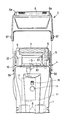
本発明を、図1ないし図15に示す水洗い式のロータリ式電気かみそりを例にとって説明する。電気かみそりは握り部を兼ねるかみそり本体1と、その上部のヘッド部4に着脱自在に装着した外刃6を備える外刃ホルダー2と、かみそり本体1の背面上部に配置した内刃3用の清掃具などを備えている。ヘッド部4の上面左右には、左右一対の内刃支持枠5が設けてあり、一対の内刃支持枠5の上端間に、横軸まわりに回転する内刃3が軸支してある。図1または図2に示すように内刃3を駆動するために、かみそり本体1の内部にモータ7とモータ7に電力を供給するための二次電池8および二次電池8を充電するための充電回路75とを設けてあり、モータ7の動力はギヤ伝動機構9を介して内刃3に伝わる。ギヤ伝動機構9は、図2におけるヘッドケース10の右方の内刃支持枠5の内部に組み込んである。
【0022】
図1中、符号11はモータ7起動用のスイッチノブである。スイッチノブ11は、プッシュ式のスイッチ形態であり、図10に示すように、後述するレンズ体に熱溶着された弾性アーム79と一体成形されて構成するものである。スイッチノブ11は弾性アーム79によって、外方側(図に向かって左方向)に向けた付勢力を受けているので、スイッチノブ11が押し込まれても弾性アーム79の弾勢力によってもとの位置に即座に復帰する。
【0023】
スイッチノブ11の背面と対向する部位には、マイクロスイッチ77が設けられており、スイッチノブ11の操作により、防水シート84を介してON・OFF駆動される。マイクロスイッチ77の信号は制御回路76に送信され、制御回路76は、それを受けてモータ7を駆動する。モータ7は、再度マイクロスイッチ77が駆動するまで、すなわちスイッチノブ11が押されるまで回転駆動を続ける。
【0024】
78は、スイッチノブ11が不用意に押され誤動作をするのを防止するロック体である。ロック体78を下方にスライドさせることによって、スイッチノブ11の上面に形成された係合凹部82にロック体78の係合突起81が嵌まり、スイッチノブ11の移動は阻止される。通常、ロック体78を下方にスライドさせておくことで、誤動作を防止できる。スイッチノブはプッシュ式に限らず、公知のスライド式、回転式を適用することもできる。
【0025】
図1または図10において、74は、充電スタンド(図示せず)の充電用端子と接触する給電端子74であり、充電スタンドに電気かみそりを載置した状態で互いを接触させれば、二次電池8の充電状態となる。充電スタンドは、商用電源から充電アダプターとコードを介して電力の供給を受ける。また、本実施例では、充電スタンドに接続される充電アダプターのコードを直接、給電端子74に接続できるようにもなっており充電・交流両用式であるが、乾電池式の電気かみそりであってもよい。
【0026】
図中72は青色に発光する青色発光ダイオードであり、73は赤色に発光する赤色発光ダイオードである。各ダイオード72,73は図1中点線矢印に示す方向に照射されるように配設される。71は各ダイオード72,73から照射される光をかみそり前面側(図10においては左方向)に照射するための樹脂製で半透明のレンズ体である。青色発光ダイオード72は、充電池或いは交流を使用したモータ駆動時、つまりかみそり使用時に制御回路76の信号を受けて発光し、モータ7が停止するまで発光を続ける。別実施例として、制御回路76にあるタイマ回路によって、モータ7停止後、所定期間(例えば30秒)をおいて、発光を停止させるようにすることができる。これによって、使用者がスイッチをOFFし、机上などの載置面に載置した後も、なおも光り続けるので、再使用時の場所の確認を容易にし、また、発光部71がムーディーな光を発するので、インテリア性が高まる。タイマ回路を利用して、好みの時間に発光部71をONする構成(時間設定による発光手段を設ける)としてもよく、例えば、朝の目覚ましとして利用することができる。この場合、時間設定の操作スイッチを本体1上に設け別途設けられた液晶表示とともに「何時何分に発光部71をON」或いは「何時間後に発光部71をON」を設定できるようにする。このとき発光部71の発光とともに本体1に内蔵されているブザー等の発音手段も発音駆動させる。発光部71および発音手段は所定時間(例えば、1分間)でOFFするように制御部76によって制御される。もしくは、所定時間でOFFするのではなく、スイッチノブ11をON操作し、その後のOFF操作で、発光および発音を停止するようにすれば、目覚まし効果および電気かみそり使用催促の効果を奏する。また、スイッチ操作前に発光させることも考えられる。すなわち、本体1の表面に赤外線センサ、超音波センサ等のセンサ部を設け、人を感知すれば、その信号を制御回路76が受け、制御回路76によって、本体1を握る前に発光部71を発光させることができる。これによれば、暗がりでも即座に機器の位置確認ができるとともに、本体を握って使用するときも、スイッチノブ11の位置確認が容易に行えるので使い勝手が向上する。スイッチノブ11を操作してモータ7を駆動し、その後OFF操作すれば、モータ7の駆動停止とともに発光部71の発光も停止する。上述した実施例を相互に組み合わせればさらに有用な小型電気機器となる。
【0027】
赤色発光ダイオード73は、二次電池8の充電時に発光する。このとき青色発光ダイオード72は発光しない。二次電池8が満充電となると充電完了を使用者に認識させるために、赤色発光ダイオード73は点滅発光となる。青色発光ダイオード72は、もう1つ追加してレンズ体71の上方から照射するよう構成することができる。これにより、発光部としてのレンズ体71から照射される光量を増大させることができる。また、複数のダイオードによって、側方から照射させ、上下方向に万遍なく光を発するようにすることも考えられる。発光源として使用される発光ダイオードは、これに換えて、グローブ球や指向性のよいニップル球等のいわゆるまめ球を使用することも考えられる。また、使用中表示、充電中表示の発光ダイオードは青、赤色逆であってもよいし、その他の色の発光ダイオード、例えば、緑色、黄色等の発光ダイオードに換えることもできる。二次電池8としては、ニッカド電池、ニッケル水素電池等を使用する。二次電池8の概念としては、電気二重層コンデンサ、いわゆるスーパーキャパシタも含むものとする。
【0028】
青色発光ダイオード72は使用中、点灯発光し、赤色発光ダイオード73は駆動停止するものであるが、二次電池8の充電容量が少なくなると制御回路76に組み込まれる検出抵抗、増幅回路、演算回路等からなる残存容量検出手段によって、次のように動作する。すなわち、充電容量が100%から40%までは青色発光ダイオード72は点灯発光する。充電容量が40%以下になると青色発光ダイオード72は一定周期の点滅発光となり、充電の目安表示となる。そして、充電容量が、20%以下になると、青色発光ダイオード72は消え、替りに赤色発光ダイオード73が点灯発光し充電を催促するようにしている。このように動作させることで、使用者に充電残量を確実に認識させることができる。ここで赤色発光ダイオード73は軸に沿って長いレンズ体71に向けて照射する構成としているが、照射するのは青色発光ダイオード72のみとし、レンズ体71の下方部位に、別途小さなレンズ体を設け、上述した充電表示や、使用中の充電容量減少による充電催促表示を行わせるようにしてもよい(図14参照)。この場合、充電中は赤色発光ダイオード73を発光させ、満充電となると、同ダイオード73の発光を停止させると同時に青色発光ダイオード72を発光させ、使用者に満充電であることを認識させるようにしている。このとき発光部としてのレンズ体71から幻想的な光が放たれるので、インテリア性も非常によい。
【0029】
レンズ体71の内壁には、光を積極的に反射させるべく内壁に凹凸87(ローレット)が形成されている。レンズ体71の背面には、反射効果を得るために、白色、銀色などの光反射性の高い色の平面状反射シート83(図10参照)を設けている。また、反射シートを幾何学模様、動物などの図柄・絵柄入りシートとし、レンズ体を透明とすれば、レンズ体を透かして図柄・絵柄を見ることができ、各発光ダイオード72,73が発光していても発光していなくてもそれを見て楽しむことができる。これによれば、違う図柄・絵柄をそれぞれ用意し、組み込み生産することで、同じ金型で機器(電気かみそり)のバリエーション化が可能となり、コストの低減を図ることができる。各発光ダイオード72,73を発光すれば、明確に図柄・絵柄が浮き出るので楽しみ度合いが増える。レンズ体71を凸レンズ、フレネルレンズ等の拡大レンズとすれば、さらに図柄・絵柄が浮き出て見えるので楽しみも倍加する。また、反射シート83に蓄光材を塗布しておき、暗闇で発光させるようにしてもよい。反射シートは、シートに限らず、レンズ体71の装着面である本体1の凹部底面89にメッキ蒸着したり、反射率の高い白色系の樹脂を二重成形したものであってもよい。発光ダイオードは、近年開発された白色発光ダイオードを使用することも考えられる。この場合、レンズ体71に様々な色のフィルムを貼る、或いは、レンズ体71自身を色付半透明の樹脂で形成することで、バリエーションに富んだ色彩の発光部を構成でき、同じ金型の機器(電気かみそり)であっても、低コストでバリエーション化が可能となる。108はレンズ体71に形成されたスイッチノブ11挿通用の開口である。
【0030】
レンズ体71は図1および図9に示すように、本体部1の長手の軸に沿って長く形成され凹部内周面85に合致する外周面86をもつ形態を成しており、本体部1の長手の軸に沿って長く形成されている。これにより、使用中表示、充電表示の各種動作表示が視覚的にわかりやすくなる。また、使用時の電力表示の確認が日常的に身に付けられ、それが習慣となることで、例えば、電池電力が全くない状態のときに、それは故障ではなく、電池電力がない状態であることを即座に判断することができ、使用者はあわてず対処できる。電気かみそりにおいて、機種によっては、機能部の前後の方向性をはっきりさせて使用しなければならないものもあり、その場合、発光部が長ければ、はっきり前後の区別がつくので効果的である。別の応用例の中で、特に電動歯ブラシにおいては、通常、本体が円筒状に成しており、使用者の手の中で回転しやすく、機能部としてのブラシ体の方向性が定まりにくいものであるが、これを軸に沿って長い発光部によって解消できる。
【0031】
また、スイッチノブ11を、本体部1の長手の軸に沿って長く形成されたレンズ体71の近傍であって、かつ上下寸法L内に配設したことにより、スイッチノブ11の位置確認が容易となり、誤操作の少ない小型のスイッチノブ11であっても、さらに暗がりであっても良好なスイッチ操作を行うことができる。これは、スイッチノブ11より上方にも、表示部としてのレンズ体71が形成されることになるので、前述の効果をさらに顕著にする。スイッチノブ11は、レンズ体71の上下寸法L内であれば、本体1の前面に限らず、本体1の側面外面にあってもよい。この場合、レンズ体71は側面に寄せて設け、スイッチノブ11とレンズ体71を近接させることが好ましい。このように構成することによっても、スイッチノブ11の位置確認は容易になる。レンズ体71は前面側にあるので、機能部Aの前後の方向性も確認できる。
【0032】
さらに、本体部1の軸に沿って長く形成された発光部としてのレンズ体71によって、細長い電気機器の全体を浮かび上がらせつつ、スイッチノブ11周辺をぼんやり発光させるので、幻想的な雰囲気を醸し出すことができ、ファッション性に富み、興趣に富んだ電気かみそりを提供することができる。また、レンズ体71は、下方から上方に向かって末広がり状に幅を広くしており、発光源から近いところでは光量を絞り、遠ざかるにつれて開放しているので、上下方向にバランスのとれた発光を行うことができる。
【0033】
また、図1に示すように、スイッチノブ11を、発光部の幅寸法H内に配設したことにより、さらに、スイッチノブ11の位置確認を容易に行うことができる。つまり、細長く、しかし面状である大面積の発光部としてのレンズ体71の中に、スイッチノブ11が位置することになるので、例え使用時にスイッチノブ11周辺から離れた部位を握り、機器を操作していたとしても、明るいレンズ体71の内方でシルエット状にスイッチノブ11が浮かびあがることで、スイッチノブ11の位置確認が容易となり、操作性が向上する。
【0034】
スイッチノブ11を、発光部の一方側に寄せた部位に配設したことにより、そのシルエット状のスイッチノブ11と軸方向に長いレンズ体71によって、暗がりにおける使用中の不用意な落下或いは使用状態での一時載置の後の再使用時、上下方向の認識、つまり機能部の位置を即座に認識でき、使用間違いを確実に防止できる。
【0035】
発光部として、各ダイオード72,73から照射される光を反射させるレンズ体71としたことにより、少ないコストで、前述した効果を有する電気かみそりを構成することができる。また、レンズ体11によれば、発光していない状態のときでも、デザイン性に優れ意匠的に有利である。特に本実施例によれば、レンズ体11の裏側に反射シート83を配設しているので、発光していない状態のときに、外光およびレンズ体11内壁に形成されたローレット87によって、高級感のある優れた意匠の電気かみそりとなる。
【0036】
モータ7を内蔵する握り部兼用の本体1の上部に設けられた、毛を導入可能な多数の開口を有する外刃6と、外刃6に内接し上記外刃6と協働して毛をカットする内刃3とにより機能部Aは構成される。
【0037】
本実施例においては、機能部として、電気かみそりを例に挙げて説明しているので、外刃6と内刃3のカット部となっているが、その他の例として、本体の上部にジュール熱を利用する温熱ヘッドを有する温熱治療器ならば、機能部は温熱ヘッドであり、本体の上部に往復動或いは回転するブラシ体を有する電動歯ブラシならば、機能部はブラシ体であり、本体の上部に水を噴射する噴出部を有する口腔洗浄器ならば、機能部は噴出部である。その他バイブレーション式マッサージ器、遠赤外線治療器等応用例は種々考えられる。例えば温熱治療器のように音のでない小型電気機器において、本発明を採用すれば、機器使用中の問題点を解消することができる。すなわち、従来、本体部を把持する手によって、動作表示用の発光部が隠れ、動作状態を認識できず動作状態のまま、例えば床面などに置きっぱなしとし、無駄に電力を消費することがあったが、それを可及的に防止することができる。
【0038】
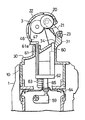
次に本電気かみそりのその他の構成を説明する。外刃ホルダー2は上下面が開口する中空枠状に形成してあり、その内面上部に外刃6が装着してある。外刃ホルダー2をヘッド部4に上方から外嵌装着することにより、外刃6が内刃3の上周面に外接する。図3に示すように外刃ホルダー2の背面に隣接する状態で清掃具を配置し、さらにその下側にきわぞり刃ユニット14を配置してある。きわぞり刃ユニット14は、切換ノブ15を上方をスライドすることのより、かみそり本体1に沿う待機位置から、後ろ向きに突出する使用位置へ跳ね上がり揺動できる。
【0039】
図7において清掃具は、ロール状のブラシ(清掃体)20と、ブラシ20を上下に揺動操作する支持アーム21と、清掃時の毛屑等の飛散を防ぐカバー22および支持アーム21に固定した支軸23などで構成する。支持アーム21を支軸23を中心にして上下揺動することによって、ブラシ20は内刃3の回転中心軸と平行な姿勢を維持した状態のままで、内刃3の周面に接触する図の清掃位置(図7の状態)と、かみそり本体1の外面に待機格納される待機位置(図4の状態)とに変位できる。さらに、外刃ホルダー2を装着した状態において、カバー22が外刃6の外面に覆い被さる外刃保護位置(図5の状態)とに変位できるようになっている。
【0040】
図4においてブラシ20は、ねじり合わされた複数の芯線25の間にブラシ毛に一群を挟持固定して円柱状に形成してある。支持アーム21は門形の枠体からなり、一対の腕部の先端寄りにおいて、カバー22を相対揺動自在に軸支している。カバー22は、断面半円形の樋状の主壁26と、主壁26の両側に張り出した側壁27とを一体に形成したプラスチック成形品からなり、両側壁27の内面内方に設けた左右一対の軸受壁24で、ブラシ20を回転自在に軸支する。主壁26の周面前後にはそれぞれ一群の通水口28が通設してある。
【0041】
内刃3とヘッド4との間には、切断された毛屑を収容する空所Sが設けられており、この空所Sに臨むヘッド部4の上面に、空所Sの前面から流入する水流を、内刃3とブラシ20とが接触する位置、即ち内刃3の周面裏側へ向かって変向案内するガイド部を設ける。
【0042】
図4においてガイド部は、ヘッドケース10の上壁を利用して形成した前段がガイド体(ガイド体)30と、前段ガイド体30に連続してヘッドケース10の上面後部に突設した後段ガイド(ガイド体)31とからなる。
【0043】
水流変向時の抵抗を軽減するために、前段ガイド体30は、後段ガイド体31に向かって上り傾斜する逆へ字状の傾斜面壁で形成し、その上端に連続して外刃ホルダー2の背壁を受け止め接当する水平の受面34を設ける。先に説明した支持アーム21の支軸23は、軸受壁36に設けた断面C字形の軸受穴に背面側から圧嵌係合される。この後段ガイド体31の背面下方の格納部37に清掃具を待機格納する。
【0044】
サイドの水ガイドとして、ヘッドケース10に嵌め込み固定される左右一対の内刃支持枠5が兼ねていて、その対向内面壁によって空所S内に流入した水流を後段ガイド体31に向かって案内する。各内刃支持枠5をヘッドケース10に組み付けた状態において、それぞれの背面下部は図6に示すように後段ガイド体31の両側前面と密着して互いに補強し合い、それぞれの構造強度を高め合うようにしてある。
【0045】
先に説明したように、ブラシ20およびカバー22は支持アーム21を上下に反転揺動させることによって、待機位置と清掃位置、さらに外刃6の外面を覆う外刃保護位置とに変位操作される。これらの各位置において、ブラシ20およびカバー22を遊動不能に位置保持するために、ヘッドケース10、軸受壁36、内刃支持枠5の前面、および外刃ホルダー2の両側上面とカバー22との間にロック構造を設けている。
【0046】
図4において、格納姿勢を保持する第1のロック構造は、係止ロック39と、係合ロック40とからなる。係止ロック39は、軸受壁36の上端後縁に突設した係止リブ41と、カバー22の内面上部に突出形成した係止突起42とからなる。係合ロック40は、カバー22の外面下部に左右の凹み形成した係合凹部43と、格納部37の底面に出没自在に組み付けられた係合ピン44からなる。係合ピン44はばね45で、上方へ突出する向きに進出付勢してある。格納時には、係止突起42を係止リブ41に引っ掛け、その状態のままでカバー22を下方回動操作して、係合凹部43を係合ピン44に係合させる。このとき係合凹部43は、その前面と係止リブ41とを結ぶ線が、カバー22と支持アーム21の連結中心を越えた後に係合ピン44と係合するので、待機格納したカバー22には、後段ガイド体31の側へ引き寄せられる向きの力が作用し、その結果、カバー22を安定した状態で格納姿勢に維持できる。
【0047】
図7において、清掃姿勢を保持する第2のロック構造は、左右の内刃支持枠5の前面上部に設けた突起46と、清掃姿勢に変位した状態において、カバー22の前側内面の両側に設けられる浅い段部47とからなり、段部47を突起46にパチンと嵌め込むことにより、カバー22を清掃位置に保持固定できる。清掃時には、内刃3を回転駆動してブラシ20を連れ回り回転させながら水洗いする。このとき、支持アーム21には、支軸23を中心にとし内刃3から遠ざかる向きのモーメントが作用する。しかし、カバー22と内刃支持枠5との係合点が、ブラシ20と内刃3との中心を結ぶ線より下方に位置しているので、先のモーメントが大きくなればなるほど、突起46と段部47とはより強固に係合し合うので、清掃途中にカバー22が外れるのを確実に防止できる。このとき、カバー22によって安全スイッチがオン操作されるが、そのことは後述する。
【0048】
図3および図5において、外刃保護姿勢を保持する第3ロック構造は、外刃6をアーチ形断面状に保形保持する、左右一対の側枠6aの外面に凹み形成した凹部48と、カバー22の側壁27に設けた弾性変形可能な係合腕49、および係合腕49の下端内面に設けた突起50とで構成する。この突起50を先の凹部48にパチンと嵌め込むことにより、カバー22を外刃保護姿勢に保持して、外刃6が他物と直接衝突を阻止できる。
【0049】
図6に示すように外刃ホルダー2は、前段ガイド体30の前縁に連続する前段壁52と、ヘッドケース10の左右側面53と後段ガイド31の前側面とに被さって、後段ガイド体31より前方の空所Sと、内刃3および内刃支持枠4の外面を覆い隠す。この装着状態をより安定化して外刃ホルダー2をぐらつきなく支持するために、後段ガイド体31の後面両側端に、斜めに傾斜するガイド壁54を形成し、このガイド壁54に対応して、外刃ホルダー2の背面開口左右側縁に嵌合リブ55を設けている。嵌合リブ55をガイド壁54に沿ってスライド係合すると、外刃ホルダー2の全体がガイド壁54でかみそり本体1の背面側へ引き寄せられるので、外刃ホルダー2をヘッド部4に対してぐらつきなく装着できる。この装着状態を維持するために、ヘッドケース10の両側にロック片56を設け、このロック片56と係合するロック解除ボタン57を外刃ホルダー2に設けている。ロック解除ボタン57を押し込み操作して、ロック片56をばねに抗して退入操作すると、外刃ホルダー2をヘッド部から取り外すことができる。
【0050】
外刃ホルダー2をかみそり本体1から取り外した状態でスイッチノブ11をオン操作すると、剥き出しになった内刃3が回転駆動されて危険である。こうした事態を避けるために、スイッチノブ11でオン・オフされる主スイッチとは別に、外刃ホルダー2の着脱に連動してモータ7への給電路をオン・オフする安全スイッチ59を設けておき、外刃ホルダー2を取り外した状態では、安全スイッチ59がオフ状態に切り換わって、内刃3の駆動を阻止できるようにしている。この安全機構を利用して、カバー22が清掃位置に位置保持された状態のおいてのみ、安全スイッチ59がオン状態に切り換わるようにしている。
【0051】
具体的には、図7に示すように外刃ホルダー2用の受動片60と、カバー22用の受動片61を備えている連動ピース62をヘッドケース10で上下スライド自在に案内し、連動ピース62をばね63で上向きに進出付勢する。連動ピース62の下面には、防水シール64を介して安全スイッチ59をオン・オフ操作する操作片65が設けてある。図6に示すように前者受動片60は受面34の右側上面に突出していて、外刃ホルダー2をヘッド部4に装着した状態において、ばね63に抗して押し込み操作される。また、カバー22用の受動片61は、ギヤ伝動機構9を収容する側の内刃支持枠5の内側面に沿って設けられており、カバー22の段部47を突起46に完全に嵌め込んだ状態において、その上端に突設した受腕61aがカバー22の前側下縁で下向きに押し込み操作される。
【0052】
本発明に係る他の実施例を以下に説明する。図11において、基本的構成は、第1実施例と同じなので、同じ部材に同じ符号を与えている。ここでは、発光部として、第1実施例のレンズ体71に換えて、エレクトロルミネッセンス(EL)素子91を配設している。EL素子91は厚さ1ミクロンm程度の薄い発光材料(例えば青色に発光させるならばセリウムを添加したストロンチウムチオガレート)を絶縁膜でサンドイッチにしたもので、絶縁膜の両側に電圧を加えれば電子のエネルギーを受けて発光材料が発光するものである。これにより、色鮮やかな表示を実現できる上、薄型平面の発光部とすることができ、機器本体の薄型化を実現できる。EL素子91は、絶縁膜の両側に透明電極を用いることによって、透明な表面パネルとすることができ、青、緑、赤色の各ELパネルを重ね合わせてフルカラーELパネルで構成することができる。この場合、例えば、電気かみそりの充電容量が減少した場合、EL素子91全体の色を順次多彩に変化させることができ、使用者に、美感を起こさせながら充電残量を確認、認識させることができるので、商品価値の高い電気かみそりを提供することができる。具体的には、第1実施例の制御回路76に組み込まれた残存容量検出手段および表示パネル駆動ドライバによって、充電容量が100%〜80%のとき青色発光、80%〜60%のとき緑色発光、60%〜40%のとき黄色発光、40%〜20%のとき赤色発光を行い、20%以下になると充電催促の表示として、例えば漫画チックに空腹の電気かみそりをイメージした動画や「EMPTY」等の動く文字をパネルに表示するようにしている。電気かみそり使用中に動画を楽しみたい場合は、それ専用の切替スイッチノブ92を本体に設けているのでそれを切替え、電源スイッチノブ11をON操作すれば、それに連動して、充電催促の動画とは違う、例えば犬や猫が遊ぶような動画をパネルに表示することができる。
【0053】
さらに、本実施例(図11)の側面には、本体側面と同一平面のプッシュ式のスイッチノブを設けている。このスイッチノブを1回押し込むことにより、故障時のときのための修理先或いは製造メーカ先の電話番号が制御回路76によってパネル表示されるようになっている。これと同時に電気かみそり本体の型番、外刃,内刃の型番及び外刃、内刃の交換時期を表示するようにしている。続けて2回、3回…と押し込むことにより、「電源アダプターは水洗いしない!」「外刃を強く持たない!」「内刃は素手で触れない!」等の取り扱い説明書と同じ警告・注意書きを表示するようにしている。また、内刃が収納される毛屑収納室内に発光素子、受光素子を上下に複数設け、毛屑の堆積量を表示パネル表示させることも考えられる。この場合のパネル表示は、毛屑ゼロの場合は、全面緑色に発光させておき、毛屑が増えるにつれ段階的にパネルの下側から赤色発光を増やしていき、毛屑処理時期には全面赤色となるようにしている。このように、その機器に関する情報データを即読み出すことができるため使い勝手が格段に向上する。この表示は最終操作から所定期間後に制御回路76によって停止するようにしている。また、EL素子に換えて、カラー液晶を採用することもできる。この場合の動作も、上記EL素子の動作と同じとする。
【0054】
図12において、本体1の前面には、第1実施例と同じ構成の発光部が幅方向に並列に配設されたものである。すなわち、青色発光ダイオード93が本体1の軸に沿って長く形成されたレンズ体101に向けて内蔵されており、それらが並列に並べられて設けられている。一番右方のレンズ体105に対応する発光ダイオードは赤色発光ダイオード97である。左方の四列の発光部としてのレンズ体101は、電池容量が減少するにつれて、左方側から消えていき、前実施例のように、残り20%になると、一番右方のレンズ体105のみの発光となり、充電催促の表示を行う。各レンズ体間は、隣り合うレンズ体に光が漏れないように、反射シートが形成されている。
【0055】
図13において、本体1の前面に、多数の青色発光ダイオード106を敷き詰めて面状に発光部を構成したものである。
【0056】
図14において、本体1の前面には軸に沿って細長いレンズ体71が設けられている。また、スイッチノブ11は、第1実施例と同じくレンズ体71の上下寸法L内であって、レンズ体71の近傍に設けられる。ロック体78は、スイッチノブ11と、レンズ体71を中心軸に線対称の位置にあり、すなわち、スイッチノブ11と同じ高さにあるので、それを使用者が認識さえすれば、スイッチノブ11とともにロック体78の位置の確認も容易となる。ただしこの場合、第1実施例のように、スイッチノブ11は、レンズ体71の幅寸法H内にはない。充電中表示用の赤色発光ダイオード73はレンズ体71の下方部位で別途に発光可能に設けられる。また、レンズ体71が、本体1の軸に対して斜めに傾斜した配置手法であったとしても、レンズ体71の上下寸法L内にスイッチノブ71が収まっていれば、そのような構成も本発明に属するものとする。
【0057】
図15において、レンズ体71の形状をU字状とし、スイッチノブ11をそのU字の中の上方に配設したものである。この場合、スイッチノブ11の位置は、レンズ体71の上下寸法L、幅寸法H内となる。なお、青色発光ダイオード72は、2列のレンズ体71の夫々に対応する下方部位に内蔵されている。これは光量確保のため施されたものである。
【0058】
前述したいずれの他の実施例も、前面パネル以外は第1実施例と同じ構成を成すものとする。レンズ体71の構成は前述の実施例に限らず、縦長のA型、L型、ロゴをかたどった形状、楕円形状など種々考えられる。
【0059】
実施例では主に、機器の使用中表示、充電催促表示、充電中表示の動作認識表示を示したが、その他に、電気かみそりや毛玉取り器等の不要物が溜まる電気機器特有の掃除催促表示など発光部を発光させる動作認識表示は種々考えられる。
【図面の簡単な説明】
【図1】本発明に係るロータリー式電気かみそりの正面図である。
【図2】外刃ホルダーを取り外した状態の正面図である。
【図3】清掃具を待機格納した状態の側面図である。
【図4】清掃具を待機格納した状態の縦断側面図である。
【図5】不使用状態における電気かみそりの側面図である。
【図6】外刃ホルダーを取り外した状態の一部破断側面図である。
【図7】安全スイッチの操作構造を示す縦断側面図である。
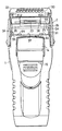
【図8】ロータリー式電気かみそりの背面図である。
【図9】レンズ体を取り外した状態斜視図である。
【図10】本発明に係る電気かみそりを模式的に表した図である。
【図11】本発明の他の実施例に係る電気かみそり正面図である。
【図12】本発明の他の実施例に係る電気かみそり正面図である。
【図13】本発明の他の実施例に係る電気かみそり正面図である。
【図14】本発明の他の実施例に係る電気かみそり正面図である。
【図15】本発明の他の実施例に係る電気かみそり正面図である。
【符号の説明】
A 機能部
H 幅寸法
L 上下寸法
1 かみそり本体
3 内刃
4 ヘッド部
6 外刃
11 スイッチノブ
71 発光部[0001]
BACKGROUND OF THE INVENTION
This invention is a hand-held type with an improved light emitting display.Electric razorIt is about.
[0002]
[Prior art]
Such a small electric device can be found in Japanese Patent Laid-Open No. 62-47394. There, an electric razor is shown as an embodiment, and an outer blade block and an inner blade block are disposed at the upper end of the housing. Further, on the front surface of the housing, there are provided a switch handle having substantially the same width as the front surface width of the housing, and a display board which is below the front surface of the housing and is long in the width direction of the housing.
[0003]
[Problems to be solved by the invention]
A small electric device having an elongated light-emitting display portion is convenient because various operation displays (in-use display, charging prompt display, charging display, cleaning prompt display, etc.) are visually easy to understand and use errors are reduced.
However, as in the above-described conventional example, if the display board is formed below the front surface of the housing and is long in the width direction, the display board is hidden by the fingers of the hand when used while being held by the hand. May not be clear. In particular, in a small electric device that does not make a sound like a thermotherapy device, the light-emitting part for operation display is hidden by the hand holding the main body part, and is left in the operating state, for example, on the floor surface. In some cases, power is wasted. In the case of the rechargeable type, since charging is normally performed while standing on a charging stand, it is difficult to understand a charging in-progress display and a charging completion display in a form in which a display board is disposed below and in the width direction. In some cases, it was not possible to charge the battery due to poor contact, without noticing that it was not charged.
[0004]
Further, in the above conventional example, the switch handle is constituted by a large switch having a width substantially the same as the front width of the housing, so that the switch handle can be easily checked, but the large switch often causes an erroneous operation.
[0005]
An object of the present invention is to make it easy for a user to visually understand various operation displays and to easily check the position of a switch knob.Electric razorIs to provide.
[0006]
Another object of the present invention is to create a fantastic atmosphere, especially in the dark, rich in fashion and interestingElectric razorIs to provide.
[0007]
[Means for Solving the Problems]
This departureTomorrowIn the upper part of the
[0008]
In addition, on the upper part of the
[0009]
Further, the
[0010]
Further, the
[0011]
Further, the
[0012]
[Operation and effect of the invention]
The
[0013]
ElectricEven if it emits sound like a razor, the confirmation of the power display during use is routinely worn, and it becomes a habit, for example, when there is no battery power at all, it is It is possible to immediately determine that it is not a failure and there is no battery power, and the user can deal with it without hesitation.
[0014]
RechargeableElectric razorIn, the display during charging can be clearly seen, and charging mistakes can be reliably prevented.
[0015]
Further, the
[0016]
Since the
[0017]
In addition, the light-emitting
[0018]
Further, since the
[0019]
Since the
[0020]
Since the light-emitting
[0021]
【Example】
The present inventionTheA water-washing rotary electric shaver shown in FIGS. 1 to 15 will be described as an example. The electric razor is a razor
[0022]
In FIG. 1,
[0023]
A
[0024]
[0025]
In FIG. 1 or FIG. 10,
[0026]
In the figure, 72 is a blue light emitting diode that emits blue light, and 73 is a red light emitting diode that emits red light. Each of the
[0027]
The red
[0028]
The blue
[0029]
On the inner wall of the
[0030]
As shown in FIGS. 1 and 9, the
[0031]
Further, since the
[0032]
In addition, the
[0033]
Further, as shown in FIG. 1, the
[0034]
Since the
[0035]
By using the
[0036]
An
[0037]
In this embodiment, an electric razor is taken as an example of the function part, and therefore, the cut part is formed by the
[0038]
Next, other configurations of the electric razor will be described. The
[0039]
In FIG. 7, the cleaning tool is fixed to a roll-shaped brush (cleaning body) 20, a
[0040]
In FIG. 4, the
[0041]
Between the
[0042]
In FIG. 4, the guide portion is a guide body (guide body) 30 that is formed using the upper wall of the
[0043]
In order to reduce the resistance at the time of turning the water flow, the
[0044]
A pair of left and right inner blade support frames 5 fitted and fixed to the
[0045]
As described above, the
[0046]
In FIG. 4, the first lock structure that holds the retracted posture includes an
[0047]
In FIG. 7, the second lock structure that holds the cleaning posture is provided on both sides of the front inner surface of the
[0048]
3 and 5, the third lock structure that holds the outer blade protection posture has a
[0049]
As shown in FIG. 6, the
[0050]
If the
[0051]
Specifically, as shown in FIG. 7, an interlocking
[0052]
Another embodiment according to the present invention will be described below. In FIG. 11, since the basic configuration is the same as that of the first embodiment, the same reference numerals are given to the same members. Here, instead of the
[0053]
Further, on the side surface of this embodiment (FIG. 11), a push-type switch knob is provided which is flush with the side surface of the main body. By pressing this switch knob once, the telephone number of the repair destination or manufacturer's destination for the time of failure is displayed on the panel by the
[0054]
In FIG. 12, on the front surface of the
[0055]
In FIG. 13, a large number of blue
[0056]
In FIG. 14, an
[0057]
In FIG. 15, the
[0058]
Any other embodiment described above has the same configuration as the first embodiment except for the front panel. The configuration of the
[0059]
In the examples, the display of the device in-use display, the charging prompt display, and the operation recognition display of the charging display is shown, but in addition to this, a cleaning reminder display peculiar to electrical equipment in which unnecessary items such as an electric razor and a hair ball remover accumulate. Various types of operation recognition displays for causing the light emitting unit to emit light are conceivable.
[Brief description of the drawings]
FIG. 1 is a front view of a rotary electric shaver according to the present invention.
FIG. 2 is a front view showing a state where an outer blade holder is removed.
FIG. 3 is a side view of a cleaning tool in a standby storage state.
FIG. 4 is a longitudinal side view of the cleaning tool in a standby state.
FIG. 5 is a side view of the electric razor in a non-use state.
FIG. 6 is a partially cutaway side view with the outer blade holder removed.
FIG. 7 is a longitudinal side view showing the operating structure of the safety switch.
FIG. 8 is a rear view of the rotary electric razor.
FIG. 9 is a perspective view showing a state where a lens body is removed.
FIG. 10 is a diagram schematically showing an electric shaver according to the present invention.
FIG. 11 is a front view of an electric razor according to another embodiment of the present invention.
FIG. 12 is a front view of an electric razor according to another embodiment of the present invention.
FIG. 13 is a front view of an electric razor according to another embodiment of the present invention.
FIG. 14 is a front view of an electric razor according to another embodiment of the present invention.
FIG. 15 is a front view of an electric razor according to another embodiment of the present invention.
[Explanation of symbols]
A Function part
H width dimension
L Vertical dimension
1 Razor body
3 inner blade
4 Head
6 outer blade
11 Switch knob
71 Light emitting part
Claims (5)
上記本体部1の外面上に、上記カット部駆動用のスイッチノブ11と、当該スイッチノブ11の操作によって発光する発光部71とを備え、
上記発光部71は、カット部の駆動時に発光するとともに、カット部の駆動が停止後も所定期間発光するよう制御し、
上記スイッチノブ11を、上記本体部1の長手の軸に沿って長く形成された発光部71の近傍であって、かつ上下寸法L内に配設したことを特徴とする電気かみそり。In the electric razor having a cut part for cutting hair on the upper part of the main body part 1 serving also as a grip part,
On the outer surface of the main body portion 1, a switch knob 11 for driving the cut portion and a light emitting portion 71 that emits light by operating the switch knob 11 are provided.
The light emitting unit 71 emits light when the cut unit is driven, and controls to emit light for a predetermined period after the drive of the cut unit is stopped.
An electric razor characterized in that the switch knob 11 is disposed in the vicinity of the light emitting portion 71 formed long along the longitudinal axis of the main body portion 1 and within the vertical dimension L.
上記本体部1の外面上に、上記カット部駆動用のスイッチノブ11と、上記蓄電池8への充電時に発光する発光部71とを備え、
上記スイッチノブ11を、上記本体部1の長手の軸に沿って長く形成された発光部71の上下寸法L内に配設したことを特徴とする電気かみそり。In the electric razor having a cut part for cutting hair on the upper part of the main body part 1 serving as a grip part containing the storage battery 8,
On the outer surface of the main body 1, the switch knob 11 for driving the cut portion and a light emitting portion 71 that emits light when charging the storage battery 8,
An electric razor characterized in that the switch knob 11 is disposed within a vertical dimension L of a light emitting portion 71 formed long along the longitudinal axis of the main body portion 1.
Priority Applications (1)
| Application Number | Priority Date | Filing Date | Title |
|---|---|---|---|
| JP24187099A JP4398018B2 (en) | 1999-08-27 | 1999-08-27 | Small electrical equipment |
Applications Claiming Priority (1)
| Application Number | Priority Date | Filing Date | Title |
|---|---|---|---|
| JP24187099A JP4398018B2 (en) | 1999-08-27 | 1999-08-27 | Small electrical equipment |
Publications (3)
| Publication Number | Publication Date |
|---|---|
| JP2001062165A JP2001062165A (en) | 2001-03-13 |
| JP2001062165A5 JP2001062165A5 (en) | 2006-10-05 |
| JP4398018B2 true JP4398018B2 (en) | 2010-01-13 |
Family
ID=17080762
Family Applications (1)
| Application Number | Title | Priority Date | Filing Date |
|---|---|---|---|
| JP24187099A Expired - Lifetime JP4398018B2 (en) | 1999-08-27 | 1999-08-27 | Small electrical equipment |
Country Status (1)
| Country | Link |
|---|---|
| JP (1) | JP4398018B2 (en) |
Families Citing this family (5)
| Publication number | Priority date | Publication date | Assignee | Title |
|---|---|---|---|---|
| GB2398533B (en) * | 2003-02-19 | 2005-11-16 | Gillette Co | Safety razors |
| JP2006334181A (en) * | 2005-06-03 | 2006-12-14 | Sanyo Electric Co Ltd | Waterproof shaver with built-in sound generation means |
| JP2008023025A (en) * | 2006-07-20 | 2008-02-07 | Matsushita Electric Works Ltd | Shaver washing device and shaver system |
| JP4681067B2 (en) * | 2009-12-04 | 2011-05-11 | 九州日立マクセル株式会社 | Switch and small electric device provided with the switch |
| JP2013222499A (en) * | 2012-04-12 | 2013-10-28 | Sharp Corp | Light source substrate unit |
Family Cites Families (7)
| Publication number | Priority date | Publication date | Assignee | Title |
|---|---|---|---|---|
| JP2544211Y2 (en) * | 1988-07-28 | 1997-08-13 | 三洋電機株式会社 | Case |
| JPH05200172A (en) * | 1992-01-28 | 1993-08-10 | Matsushita Electric Works Ltd | Electric razor |
| JPH05317539A (en) * | 1992-05-26 | 1993-12-03 | Matsushita Electric Works Ltd | Electric razor with protective cap |
| DE69615665T2 (en) * | 1995-12-14 | 2002-08-01 | Koninkl Philips Electronics Nv | DEVICE CONTAINING A RECHARGEABLE BATTERY AND A DISPLAY UNIT ON WHICH THE DISPLAY SYMBOLS DISPLAYED DURING A BATTERY CYCLE ARE DISPLAYED IN THE ACCELERATED DISPLAY MODE |
| JPH09322813A (en) * | 1996-06-06 | 1997-12-16 | Kozo Oshio | Light-emitting umbrella |
| JP3872555B2 (en) * | 1997-02-03 | 2007-01-24 | 九州日立マクセル株式会社 | Electric razor |
| JP2873001B2 (en) * | 1997-05-28 | 1999-03-24 | 株式会社アトラスオート | Emergency signal device with hammer |
-
1999
- 1999-08-27 JP JP24187099A patent/JP4398018B2/en not_active Expired - Lifetime
Also Published As
| Publication number | Publication date |
|---|---|
| JP2001062165A (en) | 2001-03-13 |
Similar Documents
| Publication | Publication Date | Title |
|---|---|---|
| US11013315B2 (en) | Light diffuser for oral cleansing devices | |
| US6802757B1 (en) | Developmental toy | |
| EP2737825B1 (en) | Illuminated flashing toothbrush | |
| JP2018069064A (en) | Cleaning appliance | |
| CN103188966A (en) | Illuminated flashing toothbrush and method of use | |
| KR102145145B1 (en) | Bubble generating assembly | |
| US8298036B2 (en) | Dynamo powered amusement device | |
| US20030115695A1 (en) | Automatic electric toothbrush in a display package | |
| JP2012523298A (en) | Small appliance with indicator element | |
| US6142846A (en) | Stuffed animal toy | |
| US20140042341A1 (en) | Apparatuses and methods for curing uv fingernail gel with minimal uv exposure | |
| CA2616648A1 (en) | Bubble generating assembly | |
| US9521899B1 (en) | Swing-triggered flashing toothbrush | |
| CN111839788B (en) | Tooth brush | |
| JP4398018B2 (en) | Small electrical equipment | |
| US20170320083A1 (en) | Sprayer nozzle with embedded battery-operated ultraviolet light(s) | |
| JP6100067B2 (en) | SWITCH STRUCTURE AND SMALL ELECTRIC DEVICE HAVING THIS SWITCH | |
| JP3130223U (en) | key ring | |
| JP2006141901A (en) | Small-sized electric apparatus | |
| JP2004041329A (en) | Communication toy with timer function | |
| KR101947497B1 (en) | Cosmetic case with rotating mirror | |
| JP4521717B2 (en) | Compact container | |
| JP3080451U (en) | Bicycle bell | |
| JP2001000215A (en) | Accessory | |
| TWM313577U (en) | Battery-free screwdriver |
Legal Events
| Date | Code | Title | Description |
|---|---|---|---|
| A521 | Written amendment |
Free format text: JAPANESE INTERMEDIATE CODE: A523 Effective date: 20060822 |
|
| A621 | Written request for application examination |
Free format text: JAPANESE INTERMEDIATE CODE: A621 Effective date: 20060822 |
|
| A977 | Report on retrieval |
Free format text: JAPANESE INTERMEDIATE CODE: A971007 Effective date: 20090709 |
|
| A131 | Notification of reasons for refusal |
Free format text: JAPANESE INTERMEDIATE CODE: A131 Effective date: 20090721 |
|
| A521 | Written amendment |
Free format text: JAPANESE INTERMEDIATE CODE: A523 Effective date: 20090918 |
|
| TRDD | Decision of grant or rejection written | ||
| A01 | Written decision to grant a patent or to grant a registration (utility model) |
Free format text: JAPANESE INTERMEDIATE CODE: A01 Effective date: 20091020 |
|
| A01 | Written decision to grant a patent or to grant a registration (utility model) |
Free format text: JAPANESE INTERMEDIATE CODE: A01 |
|
| A61 | First payment of annual fees (during grant procedure) |
Free format text: JAPANESE INTERMEDIATE CODE: A61 Effective date: 20091022 |
|
| FPAY | Renewal fee payment (event date is renewal date of database) |
Free format text: PAYMENT UNTIL: 20121030 Year of fee payment: 3 |
|
| R150 | Certificate of patent or registration of utility model |
Ref document number: 4398018 Country of ref document: JP Free format text: JAPANESE INTERMEDIATE CODE: R150 Free format text: JAPANESE INTERMEDIATE CODE: R150 |
|
| FPAY | Renewal fee payment (event date is renewal date of database) |
Free format text: PAYMENT UNTIL: 20121030 Year of fee payment: 3 |
|
| S111 | Request for change of ownership or part of ownership |
Free format text: JAPANESE INTERMEDIATE CODE: R313111 |
|
| FPAY | Renewal fee payment (event date is renewal date of database) |
Free format text: PAYMENT UNTIL: 20121030 Year of fee payment: 3 |
|
| R350 | Written notification of registration of transfer |
Free format text: JAPANESE INTERMEDIATE CODE: R350 |
|
| FPAY | Renewal fee payment (event date is renewal date of database) |
Free format text: PAYMENT UNTIL: 20121030 Year of fee payment: 3 |
|
| FPAY | Renewal fee payment (event date is renewal date of database) |
Free format text: PAYMENT UNTIL: 20131030 Year of fee payment: 4 |
|
| R250 | Receipt of annual fees |
Free format text: JAPANESE INTERMEDIATE CODE: R250 |
|
| FPAY | Renewal fee payment (event date is renewal date of database) |
Free format text: PAYMENT UNTIL: 20131030 Year of fee payment: 4 |
|
| R250 | Receipt of annual fees |
Free format text: JAPANESE INTERMEDIATE CODE: R250 |
|
| R250 | Receipt of annual fees |
Free format text: JAPANESE INTERMEDIATE CODE: R250 |
|
| R250 | Receipt of annual fees |
Free format text: JAPANESE INTERMEDIATE CODE: R250 |
|
| R250 | Receipt of annual fees |
Free format text: JAPANESE INTERMEDIATE CODE: R250 |
|
| R250 | Receipt of annual fees |
Free format text: JAPANESE INTERMEDIATE CODE: R250 |
|
| S531 | Written request for registration of change of domicile |
Free format text: JAPANESE INTERMEDIATE CODE: R313531 |
|
| S533 | Written request for registration of change of name |
Free format text: JAPANESE INTERMEDIATE CODE: R313533 |
|
| R350 | Written notification of registration of transfer |
Free format text: JAPANESE INTERMEDIATE CODE: R350 |
|
| R250 | Receipt of annual fees |
Free format text: JAPANESE INTERMEDIATE CODE: R250 |
|
| EXPY | Cancellation because of completion of term |