JP4394340B2 - Liquid fuel cell - Google Patents
Liquid fuel cell Download PDFInfo
- Publication number
- JP4394340B2 JP4394340B2 JP2002292836A JP2002292836A JP4394340B2 JP 4394340 B2 JP4394340 B2 JP 4394340B2 JP 2002292836 A JP2002292836 A JP 2002292836A JP 2002292836 A JP2002292836 A JP 2002292836A JP 4394340 B2 JP4394340 B2 JP 4394340B2
- Authority
- JP
- Japan
- Prior art keywords
- liquid fuel
- main body
- fuel cell
- valve
- external tank
- Prior art date
- Legal status (The legal status is an assumption and is not a legal conclusion. Google has not performed a legal analysis and makes no representation as to the accuracy of the status listed.)
- Expired - Fee Related
Links
Images


Classifications
-
- Y—GENERAL TAGGING OF NEW TECHNOLOGICAL DEVELOPMENTS; GENERAL TAGGING OF CROSS-SECTIONAL TECHNOLOGIES SPANNING OVER SEVERAL SECTIONS OF THE IPC; TECHNICAL SUBJECTS COVERED BY FORMER USPC CROSS-REFERENCE ART COLLECTIONS [XRACs] AND DIGESTS
- Y02—TECHNOLOGIES OR APPLICATIONS FOR MITIGATION OR ADAPTATION AGAINST CLIMATE CHANGE
- Y02E—REDUCTION OF GREENHOUSE GAS [GHG] EMISSIONS, RELATED TO ENERGY GENERATION, TRANSMISSION OR DISTRIBUTION
- Y02E60/00—Enabling technologies; Technologies with a potential or indirect contribution to GHG emissions mitigation
- Y02E60/30—Hydrogen technology
- Y02E60/50—Fuel cells
Description
【0001】
【発明の属する技術分野】
本発明は燃料として液体を用いた液体燃料電池と液体燃料電池用外部タンクに関する。
【0002】
【従来の技術】
近年、パソコン、携帯電話などのコードレス機器の普及に伴い、その電源である二次電池はますます小型化、高容量化が要望されている。現在、エネルギー密度が高く、小型軽量化が図れる二次電池としてリチウムイオン二次電池が実用化されており、ポータブル電源として需要が増大している。しかし、使用されるコードレス機器の種類によっては、このリチウム二次電池では未だ十分な連続使用時間を保証する程度までには至っていない。
【0003】
このような状況の中で、上記要望に応え得る電池の一例として、空気電池、燃料電池などが考えられる(例えば、特許文献1、特許文献2参照。)。空気電池は、空気中の酸素を正極の活物質として利用する電池であり、電池内容積の大半を負極の充填に費やすことが可能であることから、エネルギー密度を増加させるためには好適な電池であると考えられる。しかし、この空気電池には、電解液として使用するアルカリ溶液が空気中の二酸化炭素と反応して劣化してしまう問題がある。
【0004】
一方、従来の燃料電池では、単電池を積層して構成されているため、嵩高くなり、また酸素および燃料をそれぞれの正極および負極に流通させて供給しなければならず、燃料供給のための補器を必要とする。その結果、従来の燃料電池はリチウムイオン電池などの小型二次電池に比べてはるかに大きくなってしまい、小型ポータブル電源として用いるには問題があった。
【0005】
【特許文献1】
特開昭60−200468号公報
【0006】
【特許文献2】
特開2001−223018号公報
ここで、酸素および燃料を強制的に流通させる補器を除去することで出力は低下するものの、燃料電池の小型化を図ることはできる。しかし、複数の電極・電解質一体化物を積み重ねていく積層構造を有する燃料電池では、小型化には限界がある。
【0007】
これに対し、複数の電極・電解質一体化物をそれぞれ同一平面上に配置すると、燃料タンクを共有でき、空気との接触も良好となり、さらに前記積層構造に比べて電池を小型化できる。
【0008】
図13に従来の平面構造の液体燃料電池の断面図を示す。図13において、隣り合う正極8と負極9とは負極集電体7a、正極集電体7bおよび集電リード部11とで電気的に接続されている。また、この接続部近傍で液体燃料4の封止を電気的絶縁体27で行っている。液体燃料4は燃料タンク28に貯蔵されており、燃料タンク28内には燃料吸い上げ材5cが配置されている。また、燃料電池の使用時間を長くする手法として、図14に示すように燃料タンク28を電池本体とは別に設けて、配管で液体燃料4を流通させて電池本体の発電部に供給する方法もある。
【0009】
【発明が解決しようとする課題】
上記いずれの構造の燃料電池であっても、電池を長期間継続して使用するためには、液体燃料の補給が必要となる。また、液体燃料の種類によっては使用状況に応じて、液体燃料の交換を要する場合もあり、液体燃料を燃料タンクへ供給するだけでなく、液体燃料を燃料タンクから排出する必要もある。
【0010】
従来、この液体燃料の供給または排出は、燃料充填口6cを通して行っていた。しかし、この方法では、液体燃料が漏液しやすく、一般使用者の使用に不便であるという問題があった。
【0011】
本発明は、液体燃料の供給および排出を液漏れすることなく確実に行うことができる液体燃料電池と液体燃料電池用外部タンクを提供する。
【0012】
【課題を解決するための手段】
本発明の液体燃料電池は、本体部と外部タンクとを含み、前記本体部は、酸素を還元する正極と、燃料を酸化する負極と、前記正極と前記負極との間に設けられた電解質層と、液体燃料貯蔵部とを備え、前記外部タンクは、液体燃料を収容可能に形成されている液体燃料電池であって、
前記本体部と前記外部タンクとは着脱可能に形成され、
前記液体燃料貯蔵部と前記外部タンクとは、それぞれ開口部を備え、
前記液体燃料貯蔵部の開口部と前記外部タンクの開口部とは、それぞれ開閉可能な弁および前記それぞれの弁に対するストッパーを備え、
前記液体燃料貯蔵部の弁と前記外部タンクの弁とは、相互に当接して押圧されることにより開放され、
液体燃料が流入する側の前記弁の開放圧力が、液体燃料が流出する側の前記弁の開放圧力より小さく設定されており、
前記液体燃料貯蔵部および前記外部タンクは、前記開口部の前記それぞれの弁が開放されることにより液体燃料の供給または排出が可能となることを特徴とする。
【0015】
【発明の実施の形態】
以下、本発明の実施形態を説明する。
【0016】
本発明の液体燃料電池の一実施形態は、酸素を還元する正極と、燃料を酸化する負極と、前記正極と前記負極との間に設けられた電解質層と、液体燃料貯蔵部とを備えている。また、前記液体燃料貯蔵部は液体燃料を外部から供給または排出するための開口部を備え、前記液体燃料貯蔵部の開口部は弁を備え、前記開口部の弁は外部から押圧されることにより開放される。
【0017】
液体燃料電池の本体側にある液体燃料貯蔵部の開口部に弁を設けることにより、液体燃料電池の使用時における液体燃料の漏液を防止できるとともに、液体燃料の供給または排出の際における漏液をも防止できる。
【0018】
また、本発明の液体燃料電池の他の実施形態は、本体部と外部タンクとを含み、前記本体部は、酸素を還元する正極と、燃料を酸化する負極と、前記正極と前記負極との間に設けられた電解質層と、液体燃料貯蔵部とを備えている。前記本体部と前記外部タンクとは着脱可能に形成され、前記本体部の液体燃料貯蔵部と前記外部タンクとはそれぞれ開口部を備え、それらの開口部を通して液体燃料が供給または排出される。前記本体部の開口部と前記外部タンクの開口部とは、それぞれ弁(例えば、球状または円柱状の弁体)およびストッパーを備えている。前記本体部の弁と前記外部タンクの弁とは、相互に当接して押圧されることにより開放され、液体燃料が流入する側の前記弁の開放圧力が、液体燃料が流出する側の前記弁の開放圧力より小さく設定されている。
【0019】
より具体的には、前記外部タンクが液体燃料を供給するための供給タンクである場合には、前記本体部の弁の開放圧力が前記供給タンクの弁の開放圧力より小さく設定されている。これにより、本体部と供給タンクとを接続して液体燃料を供給する際、液体燃料が流入する側の本体部の弁が最初に開放して受け入れ準備が完了した後に、液体燃料が流出する側の供給タンクの弁が開放するため、液体燃料の供給開始時に液漏れすることはない。また、液体燃料の供給が終了して本体部と供給タンクとを分離する際には、最初に液体燃料が流出する側の供給タンクの弁が閉じて液体燃料の供給が完全に止まった後に、液体燃料が流入する側の本体部の弁が閉じるため、液体燃料の供給終了時に液漏れすることはない。
【0020】
また、前記外部タンクが液体燃料を排出するための排出タンクである場合には、前記本体部の弁の開放圧力が前記排出タンクの弁の開放圧力より大きく設定されている。これにより、本体部と排出タンクとを接続して液体燃料を排出する際、液体燃料が流入する側の排出タンクの弁が最初に開放して受け入れ準備が完了した後に、液体燃料が流出する側の本体部の弁が開放するため、液体燃料の排出開始時に液漏れすることはない。また、液体燃料の排出が終了して本体部と排出タンクとを分離する際には、最初に液体燃料が流出する側の本体部の弁が閉じて液体燃料の排出が完全に止まった後に、液体燃料が流入する側の排出タンクの弁が閉じるため、液体燃料の排出終了時に液漏れすることはない。
【0021】
さらに、本実施形態の液体燃料電池は、液体燃料の供給および排出の途中においても外部への液漏れがなく、また、本体部と外部タンクとを着脱可能として分離することができるため、本体部の液体燃料貯蔵部を最小にでき、電極、電解質、集電体などの発電要素を集約でき、液体燃料電池の小型化を図ることができる。また、液体燃料の供給と排出を本体部の同一の開口部で行うことができるので、供給タンクのためのスペースと排出タンクのためのスペースを別々に2つ設ける必要がなく、装置の小型化を図ることができる。また、液体燃料の供給タンクの抜き差しができるので、液体燃料電池の実装機器への未使用時には、供給タンクを除去することで液体燃料の供給遮断が容易に可能で、液体燃料電池の寿命を延ばすことができる。加えて、液体燃料電池を長時間使用する時には、供給タンクを装着したままにすれば、十分な液体燃料を供給できる。
【0022】
また、開放前の前記本体部の弁と、開放前の前記外部タンクの弁とは、それぞれ環状の液体燃料封止部(例えば、封止リング)に押圧されていることが好ましい。弁が閉じている状態での液体燃料の流出を防止できるからである。
【0023】
また、前記外部タンクの外装部には、環状部材(例えば、タンクシールガスケット)が配置されていることが好ましい。液体燃料の供給・排出の際に、本体部と外部タンクとの隙間から外部へ液体燃料が流出すること防止できるからである。
【0024】
また、前記液体燃料封止部および前記環状部材は、シリコーンゴム、フッ素ゴム、ブチルゴム、ウレタンゴム、ポリプロピレン、ナイロンおよびポリエチレンからなる群から選択された少なくとも1種類からなることが好ましい。これらは、液体燃料の密閉性に優れた材料だからである。
【0025】
また、前記本体部の開口部の外側および前記外部タンクの開口部の外側の少なくとも一方には、保液スリット(例えば、環状スリット)が設けられていることが好ましい。液体燃料の供給・排出の終了後に、この保液スリットに残った液体燃料が保持され、外部への液体燃料の流出を防止できるからである。
【0026】
また、前記本体部には、前記外部タンクを挿入可能な挿入口が備えられていることが好ましい。液体燃料の供給・排出の際に、本体部と外部タンクとを容易に固定できるからである。
【0027】
また、前記本体部の開口部が前記本体部の挿入口の内部に設けられ、前記挿入口の直径が10mm以下であることが好ましく、より好ましくは3〜8mmの範囲である。本体部の弁に手指が触れることがなくなり、誤って弁が開放することを防止できるからである。
【0028】
また、前記本体部の挿入口の周辺に開閉式シャッタを設けることが好ましい。本体部の挿入口へ異物が混入することによるトラブルを未然に防ぐことができ、さらに本体部の弁の意に反する開放を防止して安全性を高めることができるからである。
【0029】
また、前記外部タンクは、その外面部に凸部(例えば、固定用プランジャ)を備え、前記本体部の挿入口の内面部には凹部(例えば、固定用爪)を備え、前記凸部と前記凹部とが嵌合することが好ましい。または、前記外部タンクは、その外面部に凹部を備え、前記本体部の挿入口の内面部には凸部を備え、前記凸部と前記凹部とが嵌合することが好ましい。液体燃料の供給・排出の際に、凹凸部がかみ合うことで本体部と外部タンクとを容易に固定できるからである。
【0030】
また、前記本体部の挿入口の内面部に備えられた凸部の位置が、前記外部タンクの種類に応じて変更可能なことが好ましい。供給タンクと排出タンクの凹部の位置を相違させておくことにより、供給タンクと排出タンクとを間違えることなく挿入できるからである。
【0031】
また、本実施形態の液体燃料電池は、前記正極と、前記負極と、前記電解質層とが、電極・電解質一体化物を構成し、前記電極・電解質一体化物が同一平面上に配置されていることが好ましい。電池の厚みを薄くすることが可能となるからである。
【0032】
また、前記電極・電解質一体化物を複数備え、前記電極・電解質一体化物の各電解質層は、相互に連続した一体化物として形成されていることが好ましい。部品点数や組立て工数の削減を図れるからである。
【0033】
また、本実施形態の液体燃料電池は、液体燃料を含浸して保持し且つ前記負極に前記液体燃料を供給する液体燃料含浸部(例えば、燃料吸い上げ材)を備え、前記液体燃料含浸部が前記負極と接する部分に配置されていることが好ましい。液体燃料が消費されても、液体燃料と負極との接触が維持されるため、液体燃料を最後まで使い切ることができるからである。
【0034】
また、前記液体燃料貯蔵部および前記外部タンクから選択される少なくとも一つは、気液分離孔を備え、前記気液分離孔には気液分離膜が配置されていることが好ましい。液体燃料を漏液させることなく、放電反応で生成した二酸化炭素などを外部に放出できるからである。
【0035】
さらに、本実施形態の液体燃料電池の液体燃料の供給・排出方法は、前記液体燃料電池の液体燃料の供給・排出方法であり、先ず、前記本体部と前記外部タンクとを接続し、前記本体部の弁と前記外部タンクの弁とを当接させ、前記本体部の弁と前記外部タンクの弁とを相互に押圧して、液体燃料が流入する側の弁を開放した後にこの開放した弁をストッパーに当接させる。その後、さらに前記本体部の弁と前記外部タンクの弁とを相互に押圧して、液体燃料が流出する側の弁を開放し、前記本体部の液体燃料貯蔵部と前記外部タンクとの間で液体燃料を供給または排出する。
【0036】
液体燃料の供給または排出が終了した後に、前記本体部の弁と前記外部タンクの弁との押圧を緩めて、前記液体燃料が流出する側の弁を閉じ、その後、さらに前記本体部の弁と前記外部タンクの弁との押圧を緩めて、前記液体燃料が流入する側の弁を閉じる。
【0037】
これにより、外部への液漏れなく外部タンクを着脱可能とすることができ、容易に液体燃料の供給、排出及び遮断を行い、液体燃料電池を継続して長期間使用できる。
【0038】
また、本実施形態の液体燃料電池の液体燃料の供給・排出方法は、前記液体燃料が流入する側の弁を閉じた後に、前記本体部と前記外部タンクとを分離することができる。
【0039】
なお、本発明は、酸素および燃料をそれぞれの正極および負極に流通させて供給する補器を備えた液体燃料電池においても適用可能であり、これにより液体燃料貯蔵部の省スペース化を図れることで全体の大きさを小さくできる。
【0040】
次に、本発明の実施形態を図面に基づき説明する。
【0041】
(実施形態1)
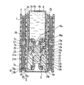
図1に本発明の液体燃料電池の本体部(a)と外部タンク(b)の実施形態の断面図を示す。
【0042】
先ず、本実施形態の液体燃料電池の本体部を説明する。図1において、本体部24は、その両側の外面にカバー板2を備え、カバー板2には空気孔1が複数設けられている。これにより、空気孔1を通して大気中の酸素が後述する正極8と接することになる。本体部24は、例えば、ポリテトラフルオロエチレン(PTFE)、硬質ポリ塩化ビニル、ポリプロピレン、ポリエチレンなどの合成樹脂や、ステンレス鋼などの耐食性金属で形成される。
【0043】
また、液体燃料貯蔵部5が、カバー板2と対向する位置および本体部24の側面部に設けられている。カバー板2と液体燃料貯蔵部5との間には、正極8、負極9、電解質層10などからなる発電部が配置されている。
【0044】
正極8は、例えば、多孔性の炭素材料からなる拡散層8aと、触媒を担持した炭素粉末からなる触媒層8bとを積層して構成される。正極8は酸素を還元する機能を有しており、その触媒には、例えば、白金微粒子や、鉄、ニッケル、コバルト、錫、ルテニウムまたは金などと白金との合金微粒子などが用いられる。また、触媒層8bには、PTFE樹脂粒子やプロトン交換樹脂粒子が含まれる場合がある。プロトン交換樹脂粒子としては、例えば、ポリパーフルオロスルホン酸樹脂やスルホン化ポリエーテルスルホン酸樹脂、スルホン化ポリイミド樹脂などを用いることができる。拡散層8aの触媒層側には撥水性向上のため、PTFE樹脂粒子を含む炭素粉末のペーストが塗布されている場合もある。
【0045】
電解質層10は、電子伝導性を持たず、プロトンを輸送することが可能な材料により形成される。例えば、ポリパーフルオロスルホン酸樹脂膜、具体的には、デュポン社製の“ナフィオン”(商品名)、旭硝子社製の“フレミオン”(商品名)、旭化成工業社製の“アシプレックス”(商品名)などにより電解質層10を形成することができる。その他では、スルホン化ポリエーテルスルホン酸樹脂膜、スルホン化ポリイミド樹脂膜、硫酸ドープポリベンズイミダゾール膜などからも形成することができる。
【0046】
負極9は、拡散層9aと触媒層9bとからなり、燃料からプロトンを生成する機能、即ち燃料を酸化する機能を有しており、例えば、正極と同様に形成することができる。
【0047】
上記正極8、上記負極9および上記電解質層10は、積層されて電極・電解質一体化物を形成している。即ち、電極・電解質一体化物は、正極8と、負極9と、正極8と負極9との間に設けられた電解質層10とから形成されている。また、この電極・電解質一体化物は、平面状に複数個配置されている。
【0048】
各電極・電解質一体化物の間には、電気的絶縁体27が配置され、各電極・電解質一体化物間の短絡を防止するとともに、液体燃料の正極側や電池外への流出を防止している。電気的絶縁体27は、シリコーンゴム、フッ素ゴム、ブチルゴム、ウレタンゴムやポリプロピレン、ナイロン、ポリエチレンなどの弾性絶縁樹脂で形成されている。
【0049】
正極8の電解質層10とは反対側の、正極8と接する箇所には正極集電体7bが設置され、負極9の電解質層10とは反対側の、負極9と接する箇所には負極集電体7aが設置されており、隣接する正極集電体7bの一部と負極集電体7aの一部とが、連結集電体7cで電気的に接続されている。これらの集電体7a、7b、7cは、例えば、白金、金などの貴金属や、ステンレス鋼などの耐食性金属、またはカーボンなどの導電性部材から形成されている。
【0050】
負極9と接する部分には燃料供給孔29が設けられており、この部分から液体燃料が負極9へと供給される。また、液体燃料を含浸して保持し且つ負極9に液体燃料を供給する燃料吸い上げ材5aが、液体燃料貯蔵部5の内部に配置されている。これにより、液体燃料が消費されても、液体燃料と負極9との接触が維持されるため、液体燃料を最後まで使い切ることができる。燃料吸い上げ材5aとしては、ガラス繊維を用いることができるが、液体燃料の含浸によって寸法が余り変化せず、化学的にも安定なものであれば他の材料を用いても良い。
【0051】
また、本体部24の中央部には、外部タンク3を挿入するための挿入口25が設けられている。挿入口25の先には、液体燃料を供給または排出するための開口部17が設けられている。開口部17には樹脂製または金属製である球状の弁体12bが備えられ、弁体12bは圧縮バネ13bにより封止リング21bに押圧されている。また、封止リング21bに対向する位置にはストッパー14bが設けられ、その下部にはストッパーガスケット15bが配置されている。開口部17の外側には、環状スリット20が設けられている。さらに、環状スリット20に隣接して圧縮吸収材18が備えられている。
【0052】
次に、本実施形態の液体燃料電池の外部タンクについて説明する。外部タンク3は、液体燃料電池の本体部24へ液体燃料4を供給する場合には供給タンク3aとなり、本体部24から液体燃料4を排出する場合には排出タンク3bとなる。液体燃料4としては、例えば、メタノール水溶液、エタノール水溶液、ジメチルエーテル、水素化ホウ素ナトリウム水溶液、水素化ホウ素カリウム水溶液、水素化ホウ素リチウム水溶液などが用いられる。
【0053】
外部タンク3は、例えば、PTFE、硬質ポリ塩化ビニル、ポリプロピレン、ポリエチレンなどの合成樹脂や、ステンレス鋼などの耐食性金属から形成することができる。
【0054】
次いで、本実施形態の液体燃料電池の液体燃料の供給または排出の方法について説明する。
【0055】
先ず、外部タンク3が供給タンク3aである場合を説明する。供給タンク3aは本体部24の挿入口25に挿入でき、着脱が可能である。供給タンク3aの先端部には、液体燃料4を供給するための開口部16aが設けられている。開口部16aには樹脂製または金属製である球状の弁体12aが備えられ、弁体12aは圧縮バネ13aにより封止リング21aに押圧されている。また、封止リング21aに対向する位置にはストッパー14aが設けられ、その下部にはストッパーガスケット15aが配置されている。
【0056】
また、本体部24の弁体12bの圧縮バネ13bの圧縮力は、供給タンク3aの弁体12aの圧縮バネ13aの圧縮力より小さく設定してある。これにより、本体部24に供給タンク3aを接続する際には、本体部24の弁体12bが最初に開放され、その後に供給タンク3aの弁体12aが開放される。逆に、本体部24から供給タンク3aを離脱する際には、供給タンク3aの弁体12aが最初に閉じられ、その後に本体部24の弁体12bが閉じられる。
【0057】
また、供給タンク3aの弁体12aと本体部24の弁体12bとの接触面は、本体部24の外装面より凹部にあり、本体部24の挿入口25へ供給タンク3aを挿入することで液体燃料4を供給する。
【0058】
次に、本体部24と供給タンク3aとの着脱方法をさらに詳しく説明する。図2から図5は、本体部24に供給タンク3aを装着している状態の断面図である。図2は、本体部24の挿入口25に供給タンク3aを挿入した最初の段階を示しており、弁体12aおよび弁体12bはともに閉じている。ここで、さらに供給タンク3aを本体部24に押し込むと、図3に示すように、供給タンク3aの弁体12aと本体部24の弁体12bが衝突する。ここで、さらに供給タンク3aを本体部24に押し込むと、本体部24の弁体12bの圧縮バネ13bの圧縮力は、供給タンク3aの弁体12aの圧縮バネ13aの圧縮力より小さく設定してあるので、図4に示すように、本体部24の弁体12bが封止リング21bから離れ、弁体12bが最初に開放される。次に、さらに供給タンク3aを本体部24に押し込むと、本体部24の弁体12bがストッパー14bに当接する。ここで、さらに供給タンク3aを本体部24に押し込むと、図5に示すように、供給タンク3aの弁体12aは封止リング21aから離れ、弁体12aが開放され、液体燃料4が供給タンク3aの開口部16a、接続部中間室19および本体部24の開口部17を流通して、液体燃料貯蔵部5の燃料吸い上げ材5aに供給される。
【0059】
次に、供給タンク3aを引き抜くときは挿入の際とは逆の順番となり、図5の状態から供給タンク3aの弁体12aが最初に閉じられ、接続部中間室19内の液体燃料4が液体燃料貯蔵部5内に流入してから、本体部24の弁体12bが閉じられ、図4の状態へと戻る。
【0060】
次に、外部タンク3が排出タンク3bである場合を説明する。排出タンク3bは本体部24の挿入口25に挿入でき、着脱が可能である。排出タンク3bの先端部には、液体燃料4を排出するための開口部16bが設けられている。開口部16bには樹脂製または金属製である球状の弁体12cが備えられ、弁体12cは圧縮バネ13cにより封止リング21cに押圧されている。また、封止リング21cに対向する位置には、ストッパー14cが設けられ、その下部にはストッパーガスケット15cが配置されている。
【0061】
また、本体部24の弁体12bの圧縮バネ13bの圧縮力は、排出タンク3bの弁体12cの圧縮バネ13cの圧縮力より大きく設定してある。これにより、本体部24に排出タンク3bを接続する際には、排出タンク3bの弁体12cが最初に開放され、その後に本体部24の弁体12bが開放される。逆に、本体部24から排出タンク3bを離脱する際には、本体部24の弁体12bが最初に閉じられ、その後に排出タンク3bの弁体12cが閉じられる。
【0062】
また、排出タンク3bの弁体12cと本体部24の弁体12bとの接触面は、本体部24の外装面より凹部にあり、本体部24の挿入口25へ排出タンク3bを挿入することで液体燃料4を排出する。
【0063】
次に、本体部24と排出タンク3bとの着脱方法をさらに詳しく説明する。図6から図9は、本体部24に排出タンク3bを装着している状態の断面図である。図6は、本体部24の挿入口25に排出タンク3bを挿入した最初の段階を示しており、弁体12cおよび弁体12bはともに閉じている。ここで、さらに排出タンク3bを本体部24に押し込むと、図7に示すように、排出タンク3bの弁体12cと本体部24の弁体12bが衝突する。ここで、さらに排出タンク3bを本体部24に押し込むと、本体部24の弁体12bの圧縮バネ13bの圧縮力は、排出タンク3bの弁体12cの圧縮バネ13cの圧縮力より大きく設定してあるので、図8に示すように、排出タンク3bの弁体12cが封止リング21cから離れ、弁体12cが最初に開放される。次に、さらに排出タンク3bを本体部24に押し込むと、排出タンク3bの弁体12cがストッパー14cに当接する。ここで、さらに排出タンク3bを本体部24に押し込むと、図9に示すように、本体部24の弁体12bは封止リング21bから離れ、弁体12bが開放され、液体燃料4が開口部17、接続部中間室19および開口部16bを流通して、排出タンク3bの燃料吸い上げ材5bに排出される。
【0064】
次に、排出タンク3bを引き抜くときは挿入の際とは逆の順番となり、図9の状態から本体部24の弁体12bが最初に閉じられ、接続部中間室19内の液体燃料4が排出タンク3b内に流入してから、排出タンク3bの弁体12cが閉じられ、図6の状態へと戻る。
【0065】
前記封止リング21a、21b、21cは、シリコーンゴム、フッ素ゴム、ブチルゴム、ウレタンゴムやポリプロピレン、ナイロン、ポリエチレンなどの弾性絶縁樹脂、またはステンレス鋼などの金属で形成することができ、また、本体部24や外部タンク3と同材質で形成することもできる。
【0066】
また、前記環状スリット20を設けることで、接続部中間室19に残存する液体燃料を保持することができ、外部への液体燃料の流出を防止できる。なお、環状スリット20は複数設けることが好ましい。また、前記圧縮吸収材18の本来の目的は、本体部24と外部タンク3との接続時の衝撃を緩和するためのものであるが、前記環状スリット20と同様の機能を有することもできる。即ち、圧縮吸収材18を設けることで、接続部中間室19に残存する液体燃料を吸収することができ、外部への液体燃料の流出を防止できる。
【0067】
供給タンク3aおよび排出タンク3bには気液分離孔6aが設けられている。この気液分離孔6aの内側には気液分離膜6bが設けられている。この気液分離膜6bは細孔を持つPTFE製シートからなり、放電反応で生成した二酸化炭素などを、液体燃料4を漏液させることなく供給タンク3aおよび排出タンク3bから放出させることができる。また、気液分離膜6bを脱着可能とすることで、液体燃料4を補充する時の充填口ともなる。なお、この気液分離孔6aは、液体燃料貯蔵部5に設けることもできる。
【0068】
また、供給タンク3aおよび排出タンク3bの外装面には、シリコーンゴム、フッ素ゴム、ブチルゴム、ウレタンゴムやポリプロピレン、ナイロン、ポリエチレンなどの弾性樹脂で形成されたタンクシールガスケット26a、26bが少なくとも一つ設けられている。これにより、液体燃料の外部への流出の防止をより確実に行える。
【0069】
また、供給タンク3aおよび排出タンク3bの外面部には、樹脂製または金属製である弾力を有する、例えば固定用プランジャ22の凸部が設けられており、本体部24の挿入口25の内面部には固定用爪23の凹部が設けられており、この凹凸部がかみ合うことで供給タンク3aおよび排出タンク3bと本体部24とが固定される。上記凹部および凸部の取り付け面は、上記の逆であってもよい。この機構により、供給タンク3aおよび排出タンク3bが固定できるとともに、確実に燃料供給状態を保持することができる。
【0070】
また、本体部24の挿入口25の周辺に開閉式シャッタ(図示せず)を設けると、異物の混入によるトラブルを未然に防ぐことができ、さらに安全性を高めることができる。
【0071】
さらに、本体部24の挿入口25の内面部に設けられた凸部の位置を変更することができる切り替えレバーを設けることもできる。その凸部と供給タンク3aおよび排出タンク3bの凹部がかみ合って対応することで、供給タンク3aと排出タンク3bとを間違えることなく挿入することができる。
【0072】
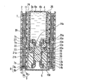
(実施形態2)
図10に実施形態2の液体燃料電池の断面図を示す。図10は、本体部24に供給タンク3aが完全に装着された状態を示す。本実施形態は、実施形態1の発電部の一部が複数個積層された構造となっていること以外は、実施形態1と同様の構造である。
【0073】
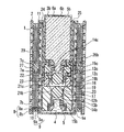
(実施形態3)
図11に実施形態3の液体燃料電池の断面図を示す。図11は、本体部24に供給タンク3aが完全に装着された状態を示す。本実施形態は、中央部に液体燃料貯蔵部5を設け、供給タンク3aの挿入口25を本体部24の側部に配置したこと以外は、実施形態1と同様の構造である。
【0074】
(実施形態4)
図12に実施形態4の液体燃料電池の断面図を示す。図12は、本体部24に供給タンク3aが完全に装着された状態を示す。本実施形態は、実施形態1の弁体12a、12bの形状が円柱状であること以外は、実施形態1と同様の構造である。
【0075】
【発明の効果】
以上のように本発明は、液体燃料の供給および排出を液漏れすることなく確実に行うことができ、小型でも長時間安定して発電できる液体燃料電池を提供できる。
【図面の簡単な説明】
【図1】 本発明の実施形態1の液体燃料電池の本体部(a)と外部タンク(b)の断面図である。
【図2】 本発明の実施形態1の液体燃料電池の本体部に供給タンクを接続する第1段階を示す断面図である。
【図3】 本発明の実施形態1の液体燃料電池の本体部に供給タンクを接続する第2段階を示す断面図である。
【図4】 本発明の実施形態1の液体燃料電池の本体部に供給タンクを接続する第3段階を示す断面図である。
【図5】 本発明の実施形態1の液体燃料電池の本体部に供給タンクを接続する第4段階を示す断面図である。
【図6】 本発明の実施形態1の液体燃料電池の本体部に排出タンクを接続する第1段階を示す断面図である。
【図7】 本発明の実施形態1の液体燃料電池の本体部に排出タンクを接続する第2段階を示す断面図である。
【図8】 本発明の実施形態1の液体燃料電池の本体部に排出タンクを接続する第3段階を示す断面図である。
【図9】 本発明の実施形態1の液体燃料電池の本体部に排出タンクを接続する第4段階を示す断面図である。
【図10】 本発明の実施形態2の液体燃料電池の断面図である。
【図11】 本発明の実施形態3の液体燃料電池の断面図である。
【図12】 本発明の実施形態4の液体燃料電池の断面図である。
【図13】 従来の液体燃料電池の断面図である。
【図14】 従来の他の液体燃料電池の断面図である。
【符号の説明】
1 空気孔
2 カバー板
3 外部タンク
3a 供給タンク
3b 排出タンク
4 液体燃料
5 液体燃料貯蔵部
5a、5b、5c 燃料吸い上げ材
6a 気液分離孔
6b 気液分離膜
6c 燃料充填口
7a 負極集電体
7b 正極集電体
7c 連結集電体
8 正極
8a 拡散層
8b 触媒層
9 負極
9a 拡散層
9b 触媒層
10 電解質層
11 集電リード部
12a、12b、12c 弁体
13a、13b、13c 圧縮バネ
14a、14b、14c ストッパー
15a、15b、15c ストッパーガスケット
16a、16b、17 開口部
18 圧縮吸収材
19 接続部中間室
20 環状スリット
21a、21b、21c 封止リング
22 固定用プランジャ
23 固定用爪
24 本体部
25 挿入口
26a、26b タンクシールガスケット
27 電気的絶縁体
28 燃料タンク
29 燃料供給孔[0001]
BACKGROUND OF THE INVENTION
The present invention relates to a liquid fuel cell using a liquid as a fuel, and External tank for liquid fuel cell About.
[0002]
[Prior art]
In recent years, with the widespread use of cordless devices such as personal computers and mobile phones, secondary batteries as power sources are increasingly required to be smaller and have higher capacities. Currently, lithium ion secondary batteries have been put into practical use as secondary batteries that have high energy density and can be reduced in size and weight, and demand for portable power sources is increasing. However, depending on the type of cordless device used, this lithium secondary battery has not yet reached a level that guarantees sufficient continuous use time.
[0003]
In such a situation, an air battery, a fuel cell, etc. can be considered as an example of a battery that can meet the above-mentioned demand (for example, see
[0004]
On the other hand, the conventional fuel cell is configured by stacking unit cells, so that it is bulky, and oxygen and fuel must be circulated and supplied to the respective positive and negative electrodes. Requires auxiliary equipment. As a result, the conventional fuel cell becomes much larger than a small secondary battery such as a lithium ion battery, and there is a problem in using it as a small portable power source.
[0005]
[Patent Document 1]
Japanese Patent Application Laid-Open No. 60-200468
[0006]
[Patent Document 2]
Japanese Patent Laid-Open No. 2001-2223018
Here, although the output is reduced by removing the auxiliary device for forcibly circulating oxygen and fuel, the fuel cell can be reduced in size. However, there is a limit to miniaturization in a fuel cell having a stacked structure in which a plurality of integrated electrodes and electrolytes are stacked.
[0007]
On the other hand, when the plurality of electrode / electrolyte integrated products are arranged on the same plane, the fuel tank can be shared, the contact with the air can be improved, and the battery can be reduced in size as compared with the laminated structure.
[0008]
FIG. 13 is a cross-sectional view of a conventional liquid fuel cell having a planar structure. In FIG. 13, the adjacent
[0009]
[Problems to be solved by the invention]
Regardless of the fuel cell having any of the above structures, in order to continuously use the battery for a long period of time, it is necessary to supply liquid fuel. Also, depending on the type of liquid fuel, the liquid fuel may need to be replaced depending on the usage situation, and it is necessary not only to supply the liquid fuel to the fuel tank but also to discharge the liquid fuel from the fuel tank.
[0010]
Conventionally, the liquid fuel is supplied or discharged through the
[0011]
The present invention relates to a liquid fuel cell capable of reliably performing supply and discharge of liquid fuel without leakage. External tank for liquid fuel cell I will provide a.
[0012]
[Means for Solving the Problems]
The liquid fuel cell of the present invention includes a main body portion and an external tank, and the main body portion includes a positive electrode for reducing oxygen, a negative electrode for oxidizing fuel, and an electrolyte layer provided between the positive electrode and the negative electrode. And a liquid fuel storage unit, wherein the external tank is a liquid fuel cell formed to be capable of containing liquid fuel,
The main body and the external tank are detachably formed,
Each of the liquid fuel storage unit and the external tank includes an opening,
The opening of the liquid fuel storage unit and the opening of the external tank can be opened and closed, respectively. valve And a stopper for each of the valves,
The valve of the liquid fuel storage unit and the valve of the external tank are opened by being pressed against each other,
The opening pressure of the valve on the liquid fuel inflow side is set smaller than the opening pressure of the valve on the liquid fuel outflow side,
The liquid fuel storage unit and the external tank can supply or discharge liquid fuel by opening the respective valves of the opening.
[0015]
DETAILED DESCRIPTION OF THE INVENTION
Embodiments of the present invention will be described below.
[0016]
An embodiment of the liquid fuel cell of the present invention includes a positive electrode that reduces oxygen, a negative electrode that oxidizes fuel, an electrolyte layer provided between the positive electrode and the negative electrode, and a liquid fuel storage unit. Yes. The liquid fuel storage unit includes an opening for supplying or discharging liquid fuel from the outside, the opening of the liquid fuel storage unit includes a valve, and the valve of the opening is pressed from the outside. Opened.
[0017]
By providing a valve at the opening of the liquid fuel storage section on the main body side of the liquid fuel cell, liquid fuel leakage during use of the liquid fuel cell can be prevented and leakage during supply or discharge of the liquid fuel can be prevented. Can also be prevented.
[0018]
Further, another embodiment of the liquid fuel cell of the present invention includes a main body and an external tank, and the main body includes a positive electrode that reduces oxygen, a negative electrode that oxidizes fuel, and the positive electrode and the negative electrode. An electrolyte layer provided therebetween and a liquid fuel storage unit are provided. The main body and the external tank are detachably formed, and the liquid fuel storage section and the external tank of the main body each have an opening, and liquid fuel is supplied or discharged through these openings. Each of the opening of the main body and the opening of the external tank includes a valve (for example, a spherical or cylindrical valve body) and a stopper. The valve of the main body and the valve of the external tank are opened by being pressed against each other, and the opening pressure of the valve on the liquid fuel inflow side is the valve on the side of liquid fuel outflow. Is set to be smaller than the opening pressure.
[0019]
More specifically, when the external tank is a supply tank for supplying liquid fuel, the valve opening pressure of the main body is set smaller than the valve opening pressure of the supply tank. Thus, when liquid fuel is supplied by connecting the main body and the supply tank, the liquid fuel flows out after the valve of the main body on the side into which the liquid fuel flows is first opened and ready for reception. Since the supply tank valve is opened, liquid leakage does not occur at the start of liquid fuel supply. In addition, when the supply of liquid fuel is finished and the main body and the supply tank are separated, the supply tank valve on the side from which the liquid fuel flows out first closes and the supply of liquid fuel stops completely. Since the valve of the main body on the side into which the liquid fuel flows is closed, no liquid leaks at the end of the supply of the liquid fuel.
[0020]
Further, when the external tank is a discharge tank for discharging liquid fuel, the opening pressure of the valve of the main body is set to be larger than the opening pressure of the valve of the discharge tank. As a result, when the liquid fuel is discharged by connecting the main body and the discharge tank, the liquid fuel flows out after the valve of the discharge tank into which the liquid fuel flows is first opened and ready for reception. Since the main body valve is opened, no liquid leaks at the start of liquid fuel discharge. In addition, when the liquid fuel is completely discharged and the main body and the discharge tank are separated, the main body valve on the side from which the liquid fuel flows out first closes and the liquid fuel discharge stops completely. Since the valve of the discharge tank on the liquid fuel inflow side is closed, no liquid leaks at the end of the discharge of the liquid fuel.
[0021]
Further, the liquid fuel cell of the present embodiment has no liquid leakage to the outside even during the supply and discharge of the liquid fuel, and the main body portion and the external tank can be separated to be detachable. The liquid fuel storage section can be minimized, power generation elements such as electrodes, electrolytes, and current collectors can be integrated, and the liquid fuel cell can be reduced in size. In addition, since the liquid fuel can be supplied and discharged through the same opening of the main body, there is no need to provide two separate spaces for the supply tank and two for the discharge tank, thereby reducing the size of the apparatus. Can be achieved. In addition, since the liquid fuel supply tank can be inserted and removed, the liquid fuel supply can be easily cut off by removing the supply tank when the liquid fuel cell mounting device is not used, thereby extending the life of the liquid fuel cell. be able to. In addition, when the liquid fuel cell is used for a long time, sufficient liquid fuel can be supplied if the supply tank is left attached.
[0022]
Moreover, it is preferable that the valve of the main body before opening and the valve of the external tank before opening are pressed against an annular liquid fuel sealing portion (for example, a sealing ring), respectively. This is because the liquid fuel can be prevented from flowing out with the valve closed.
[0023]
Moreover, it is preferable that an annular member (for example, a tank seal gasket) is disposed on the exterior portion of the external tank. This is because it is possible to prevent the liquid fuel from flowing out from the gap between the main body and the external tank when supplying and discharging the liquid fuel.
[0024]
The liquid fuel sealing part and the annular member are preferably made of at least one selected from the group consisting of silicone rubber, fluorine rubber, butyl rubber, urethane rubber, polypropylene, nylon and polyethylene. This is because these materials are excellent in sealing performance of liquid fuel.
[0025]
Further, it is preferable that a liquid retaining slit (for example, an annular slit) is provided on at least one of the outside of the opening of the main body and the outside of the opening of the external tank. This is because the liquid fuel remaining in the liquid retaining slit is held after the supply / discharge of the liquid fuel is completed, and the outflow of the liquid fuel to the outside can be prevented.
[0026]
Moreover, it is preferable that the main body portion is provided with an insertion port into which the external tank can be inserted. This is because the main body and the external tank can be easily fixed when supplying and discharging the liquid fuel.
[0027]
Moreover, it is preferable that the opening part of the said main-body part is provided in the inside of the insertion port of the said main-body part, and the diameter of the said insertion port is 10 mm or less, More preferably, it is the range of 3-8 mm. This is because fingers are prevented from touching the valve of the main body, and the valve can be prevented from being accidentally opened.
[0028]
Moreover, it is preferable to provide an openable / closable shutter around the insertion opening of the main body. This is because it is possible to prevent troubles caused by foreign matters mixed into the insertion port of the main body, and to prevent the valve opening of the main body from being opened contrary to the meaning of the valve, thereby improving safety.
[0029]
The external tank includes a convex portion (for example, a fixing plunger) on an outer surface portion thereof, and a concave portion (for example, a fixing claw) on an inner surface portion of the insertion port of the main body portion. It is preferable that the recess is fitted. Alternatively, it is preferable that the outer tank has a concave portion on an outer surface portion thereof, a convex portion on an inner surface portion of the insertion port of the main body portion, and the convex portion and the concave portion are fitted. This is because when the liquid fuel is supplied / discharged, the main body portion and the external tank can be easily fixed by engaging the concave and convex portions.
[0030]
Moreover, it is preferable that the position of the convex part provided in the inner surface part of the insertion port of the main-body part can be changed according to the kind of the external tank. This is because the supply tank and the discharge tank can be inserted without making a mistake by making the positions of the recesses of the supply tank and the discharge tank different.
[0031]
In the liquid fuel cell of the present embodiment, the positive electrode, the negative electrode, and the electrolyte layer constitute an electrode / electrolyte integrated product, and the electrode / electrolyte integrated product is arranged on the same plane. Is preferred. This is because the thickness of the battery can be reduced.
[0032]
It is preferable that a plurality of the electrode / electrolyte integrated products are provided, and each electrolyte layer of the electrode / electrolyte integrated product is formed as a continuous integrated product. This is because the number of parts and assembly man-hours can be reduced.
[0033]
In addition, the liquid fuel cell of the present embodiment includes a liquid fuel impregnation unit (for example, a fuel suction material) that impregnates and holds liquid fuel and supplies the liquid fuel to the negative electrode, and the liquid fuel impregnation unit includes the liquid fuel impregnation unit. It is preferable that the electrode is disposed at a portion in contact with the negative electrode. This is because even when the liquid fuel is consumed, the contact between the liquid fuel and the negative electrode is maintained, so that the liquid fuel can be used up to the end.
[0034]
Preferably, at least one selected from the liquid fuel storage unit and the external tank includes a gas-liquid separation hole, and a gas-liquid separation membrane is disposed in the gas-liquid separation hole. This is because the carbon dioxide generated by the discharge reaction can be released to the outside without causing the liquid fuel to leak.
[0035]
Further, the liquid fuel supply / discharge method of the liquid fuel cell according to the present embodiment is a liquid fuel supply / discharge method of the liquid fuel cell. First, the main body and the external tank are connected, and the main body is connected. The valve of the external tank and the valve of the external tank are brought into contact with each other, the valve of the main body and the valve of the external tank are pressed against each other, and the valve on the side into which the liquid fuel flows is opened. Abut the stopper. Thereafter, the valve of the main body part and the valve of the external tank are further pressed against each other to open the valve on the side where the liquid fuel flows out, and between the liquid fuel storage part of the main body part and the external tank. Supply or discharge liquid fuel.
[0036]
After the supply or discharge of the liquid fuel is finished, the pressure of the valve of the main body and the valve of the external tank is loosened, the valve on the side from which the liquid fuel flows out is closed, and then the valve of the main body The pressure with the valve of the external tank is loosened, and the valve on the side into which the liquid fuel flows is closed.
[0037]
As a result, the external tank can be attached and detached without liquid leakage to the outside, and liquid fuel can be easily supplied, discharged and shut off, and the liquid fuel cell can be used continuously for a long time.
[0038]
In the liquid fuel supply / discharge method of the liquid fuel cell according to the present embodiment, the main body and the external tank can be separated after closing the valve on the liquid fuel inflow side.
[0039]
The present invention can also be applied to a liquid fuel cell provided with an auxiliary device that circulates and supplies oxygen and fuel to the respective positive and negative electrodes, thereby reducing the space of the liquid fuel storage unit. The overall size can be reduced.
[0040]
Next, embodiments of the present invention will be described with reference to the drawings.
[0041]
(Embodiment 1)
FIG. 1 shows a cross-sectional view of an embodiment of a main body (a) and an external tank (b) of a liquid fuel cell of the present invention.
[0042]
First, the main part of the liquid fuel cell of this embodiment will be described. In FIG. 1, the
[0043]
In addition, the liquid
[0044]
The
[0045]
The
[0046]
The
[0047]
The
[0048]
Between each electrode / electrolyte integrated body, an
[0049]
A positive electrode
[0050]
A
[0051]
Further, an
[0052]
Next, the external tank of the liquid fuel cell of this embodiment will be described. The
[0053]
The
[0054]
Next, a method for supplying or discharging liquid fuel in the liquid fuel cell according to this embodiment will be described.
[0055]
First, the case where the
[0056]
Further, the compression force of the
[0057]
Further, the contact surface between the
[0058]
Next, a method for attaching and detaching the
[0059]
Next, when the
[0060]
Next, the case where the
[0061]
Further, the compression force of the
[0062]
Further, the contact surface between the
[0063]
Next, a method for attaching and detaching the
[0064]
Next, when the
[0065]
The sealing rings 21a, 21b, and 21c can be formed of silicone rubber, fluorine rubber, butyl rubber, urethane rubber, elastic insulating resin such as polypropylene, nylon, or polyethylene, or metal such as stainless steel. 24 and the
[0066]
Further, by providing the
[0067]
The
[0068]
The exterior surfaces of the
[0069]
Further, on the outer surface portions of the
[0070]
In addition, if an openable / closable shutter (not shown) is provided around the
[0071]
Furthermore, a switching lever that can change the position of the convex portion provided on the inner surface of the
[0072]
(Embodiment 2)
FIG. 10 shows a cross-sectional view of the liquid fuel cell of the second embodiment. FIG. 10 shows a state in which the
[0073]
(Embodiment 3)
FIG. 11 is a cross-sectional view of the liquid fuel cell according to the third embodiment. FIG. 11 shows a state in which the
[0074]
(Embodiment 4)
FIG. 12 shows a cross-sectional view of the liquid fuel cell of the fourth embodiment. FIG. 12 shows a state in which the
[0075]
【The invention's effect】
As described above, the present invention can provide a liquid fuel cell that can reliably supply and discharge liquid fuel without leaking, and can stably generate power for a long time even if it is small.
[Brief description of the drawings]
FIG. 1 is a cross-sectional view of a main body (a) and an external tank (b) of a liquid fuel cell according to
FIG. 2 is a cross-sectional view showing a first stage of connecting a supply tank to the main body of the liquid fuel cell according to
FIG. 3 is a cross-sectional view showing a second stage of connecting a supply tank to the main body of the liquid fuel cell according to
FIG. 4 is a cross-sectional view showing a third stage of connecting a supply tank to the main body of the liquid fuel cell according to
FIG. 5 is a cross-sectional view showing a fourth stage of connecting a supply tank to the main body of the liquid fuel cell according to
6 is a cross-sectional view showing a first stage of connecting a discharge tank to the main body of the liquid fuel cell according to
7 is a cross-sectional view showing a second stage of connecting the discharge tank to the main body of the liquid fuel cell according to
FIG. 8 is a cross-sectional view showing a third stage of connecting the discharge tank to the main body of the liquid fuel cell according to
FIG. 9 is a cross-sectional view showing a fourth stage of connecting the discharge tank to the main body of the liquid fuel cell according to
FIG. 10 is a cross-sectional view of a liquid fuel cell according to
FIG. 11 is a cross-sectional view of a liquid fuel cell according to
FIG. 12 is a cross-sectional view of a liquid fuel cell according to
FIG. 13 is a cross-sectional view of a conventional liquid fuel cell.
FIG. 14 is a cross-sectional view of another conventional liquid fuel cell.
[Explanation of symbols]
1 Air hole
2 Cover plate
3 External tank
3a Supply tank
3b Discharge tank
4 Liquid fuel
5 Liquid fuel storage
5a, 5b, 5c Fuel suction material
6a Gas-liquid separation hole
6b Gas-liquid separation membrane
6c Fuel filling port
7a Negative electrode current collector
7b Positive electrode current collector
7c Connected current collector
8 Positive electrode
8a Diffusion layer
8b Catalyst layer
9 Negative electrode
9a Diffusion layer
9b Catalyst layer
10 Electrolyte layer
11 Current collector lead
12a, 12b, 12c Valve body
13a, 13b, 13c Compression spring
14a, 14b, 14c Stopper
15a, 15b, 15c Stopper gasket
16a, 16b, 17 opening
18 Compression absorber
19 Connection room intermediate room
20 Annular slit
21a, 21b, 21c Sealing ring
22 Plunger for fixing
23 Fixing nails
24 Body
25 insertion slot
26a, 26b Tank seal gasket
27 Electrical insulator
28 Fuel tank
29 Fuel supply hole
Claims (15)
前記本体部と前記外部タンクとは着脱可能に形成され、
前記液体燃料貯蔵部と前記外部タンクとは、それぞれ開口部を備え、
前記液体燃料貯蔵部の開口部と前記外部タンクの開口部とは、それぞれ開閉可能な弁および前記それぞれの弁に対するストッパーを備え、
前記液体燃料貯蔵部の弁と前記外部タンクの弁とは、相互に当接して押圧されることにより開放され、
液体燃料が流入する側の前記弁の開放圧力が、液体燃料が流出する側の前記弁の開放圧力より小さく設定されており、
前記液体燃料貯蔵部および前記外部タンクは、前記開口部の前記それぞれの弁が開放されることにより液体燃料の供給または排出が可能となることを特徴とする液体燃料電池。The main body includes an anode for reducing oxygen, a negative electrode for oxidizing fuel, an electrolyte layer provided between the positive electrode and the negative electrode, and a liquid fuel storage unit. The external tank is a liquid fuel cell formed to be able to contain liquid fuel,
The main body and the external tank are detachably formed,
Each of the liquid fuel storage unit and the external tank includes an opening,
The opening of the liquid fuel storage unit and the opening of the external tank each include a valve that can be opened and closed and a stopper for each of the valves,
The valve of the liquid fuel storage unit and the valve of the external tank are opened by being pressed against each other,
The opening pressure of the valve on the liquid fuel inflow side is set smaller than the opening pressure of the valve on the liquid fuel outflow side,
The liquid fuel cell according to claim 1, wherein the liquid fuel storage unit and the external tank can supply or discharge the liquid fuel by opening the respective valves of the opening.
Priority Applications (1)
| Application Number | Priority Date | Filing Date | Title |
|---|---|---|---|
| JP2002292836A JP4394340B2 (en) | 2002-10-04 | 2002-10-04 | Liquid fuel cell |
Applications Claiming Priority (1)
| Application Number | Priority Date | Filing Date | Title |
|---|---|---|---|
| JP2002292836A JP4394340B2 (en) | 2002-10-04 | 2002-10-04 | Liquid fuel cell |
Publications (3)
| Publication Number | Publication Date |
|---|---|
| JP2004127824A JP2004127824A (en) | 2004-04-22 |
| JP2004127824A5 JP2004127824A5 (en) | 2005-10-06 |
| JP4394340B2 true JP4394340B2 (en) | 2010-01-06 |
Family
ID=32283974
Family Applications (1)
| Application Number | Title | Priority Date | Filing Date |
|---|---|---|---|
| JP2002292836A Expired - Fee Related JP4394340B2 (en) | 2002-10-04 | 2002-10-04 | Liquid fuel cell |
Country Status (1)
| Country | Link |
|---|---|
| JP (1) | JP4394340B2 (en) |
Families Citing this family (16)
| Publication number | Priority date | Publication date | Assignee | Title |
|---|---|---|---|---|
| KR100689334B1 (en) * | 2000-12-29 | 2007-03-08 | 주식회사 엘지이아이 | Fuel supply apparatus for fc |
| CN1922751A (en) * | 2004-02-25 | 2007-02-28 | 松下电器产业株式会社 | Fuel tank for fuel cell and fuel cell system |
| JP2006309978A (en) * | 2005-03-30 | 2006-11-09 | Toshiba Corp | Liquid injection device for fuel cell |
| JP2006286364A (en) * | 2005-03-31 | 2006-10-19 | Toshiba Corp | Liquid injector of fuel cell |
| JP2007066618A (en) * | 2005-08-30 | 2007-03-15 | Toshiba Corp | Fuel cell |
| JP2007073464A (en) * | 2005-09-09 | 2007-03-22 | Toshiba Corp | Fuel cartridge for fuel cell and fuel cell using it |
| JP2007128850A (en) * | 2005-10-05 | 2007-05-24 | Toshiba Corp | Connection structure of fuel cartridge for fuel cell, and the fuel cell using the same |
| JP2007122961A (en) * | 2005-10-26 | 2007-05-17 | Toshiba Corp | Fuel cartridge for fuel cell and fuel cell using it |
| JP4996099B2 (en) | 2006-01-19 | 2012-08-08 | 株式会社東芝 | Fuel cartridge for fuel cell, fuel cell and coupler |
| JP2007194055A (en) * | 2006-01-19 | 2007-08-02 | Toshiba Corp | Fuel cartridge for fuel cell, fuel cell, and coupler |
| JP2007273219A (en) * | 2006-03-31 | 2007-10-18 | Toshiba Corp | Fuel cartridge connection mechanism for fuel cell and fuel cell using it |
| JP2007311292A (en) | 2006-05-22 | 2007-11-29 | Toshiba Corp | Coupler for fuel cell, and fuel cell using it |
| JP2008047405A (en) | 2006-08-15 | 2008-02-28 | Toshiba Corp | Socket for fuel cell and fuel cell using the same |
| JP2008108554A (en) | 2006-10-25 | 2008-05-08 | Toshiba Corp | Fuel cartridge for fuel cell, and nozzle attachment for fuel cartridge |
| JP2009110758A (en) | 2007-10-29 | 2009-05-21 | Toshiba Corp | Coupler for fuel cell, and fuel cell |
| JP2009123575A (en) | 2007-11-16 | 2009-06-04 | Toshiba Corp | Coupler for fuel cell, and fuel cell |
-
2002
- 2002-10-04 JP JP2002292836A patent/JP4394340B2/en not_active Expired - Fee Related
Also Published As
| Publication number | Publication date |
|---|---|
| JP2004127824A (en) | 2004-04-22 |
Similar Documents
| Publication | Publication Date | Title |
|---|---|---|
| JP4394340B2 (en) | Liquid fuel cell | |
| KR100544359B1 (en) | A fuel cell power generation equipment | |
| US7046507B2 (en) | Information processing apparatus | |
| US20030198853A1 (en) | Air breathing direct methanol fuel cell pack | |
| KR20020089107A (en) | Fuel cell, fuel cell generator, and equipment using the same | |
| JP2000268835A (en) | Power generating device | |
| JP2003068325A (en) | Fuel cell | |
| JP4119188B2 (en) | Fuel cell equipment | |
| WO2003069709A1 (en) | Liquid fuel cell | |
| JP4810082B2 (en) | Fuel cell | |
| JP2003317791A (en) | Liquid fuel cell | |
| JP3917001B2 (en) | Liquid fuel cell | |
| JP2006221849A (en) | Liquid fuel battery | |
| JP4061964B2 (en) | Small fuel cell and manufacturing method thereof | |
| US20050057555A1 (en) | Information processing apparatus | |
| JP4007883B2 (en) | Liquid fuel cell | |
| JP4489419B2 (en) | Information processing device | |
| JP3992152B2 (en) | Information processing device | |
| JP2004014148A (en) | Liquid fuel cell | |
| JP3902609B2 (en) | Fuel cell power generator and device using the same | |
| JP2006156034A (en) | Liquid fuel battery | |
| JP4018500B2 (en) | Fuel cell | |
| JP2004095208A (en) | Fuel cell | |
| JP2004014149A (en) | Liquid fuel cell | |
| JP4339748B2 (en) | Fuel cell power generator and device using the same |
Legal Events
| Date | Code | Title | Description |
|---|---|---|---|
| A521 | Written amendment |
Free format text: JAPANESE INTERMEDIATE CODE: A523 Effective date: 20050526 |
|
| A621 | Written request for application examination |
Free format text: JAPANESE INTERMEDIATE CODE: A621 Effective date: 20050526 |
|
| A977 | Report on retrieval |
Free format text: JAPANESE INTERMEDIATE CODE: A971007 Effective date: 20071025 |
|
| A131 | Notification of reasons for refusal |
Free format text: JAPANESE INTERMEDIATE CODE: A131 Effective date: 20071101 |
|
| A521 | Written amendment |
Free format text: JAPANESE INTERMEDIATE CODE: A523 Effective date: 20071226 |
|
| A131 | Notification of reasons for refusal |
Free format text: JAPANESE INTERMEDIATE CODE: A131 Effective date: 20090630 |
|
| A521 | Written amendment |
Free format text: JAPANESE INTERMEDIATE CODE: A523 Effective date: 20090724 |
|
| A131 | Notification of reasons for refusal |
Free format text: JAPANESE INTERMEDIATE CODE: A131 Effective date: 20090818 |
|
| A521 | Written amendment |
Free format text: JAPANESE INTERMEDIATE CODE: A523 Effective date: 20090914 |
|
| TRDD | Decision of grant or rejection written | ||
| A01 | Written decision to grant a patent or to grant a registration (utility model) |
Free format text: JAPANESE INTERMEDIATE CODE: A01 Effective date: 20091013 |
|
| A01 | Written decision to grant a patent or to grant a registration (utility model) |
Free format text: JAPANESE INTERMEDIATE CODE: A01 |
|
| A61 | First payment of annual fees (during grant procedure) |
Free format text: JAPANESE INTERMEDIATE CODE: A61 Effective date: 20091015 |
|
| R150 | Certificate of patent or registration of utility model |
Free format text: JAPANESE INTERMEDIATE CODE: R150 |
|
| FPAY | Renewal fee payment (event date is renewal date of database) |
Free format text: PAYMENT UNTIL: 20121023 Year of fee payment: 3 |
|
| FPAY | Renewal fee payment (event date is renewal date of database) |
Free format text: PAYMENT UNTIL: 20121023 Year of fee payment: 3 |
|
| FPAY | Renewal fee payment (event date is renewal date of database) |
Free format text: PAYMENT UNTIL: 20121023 Year of fee payment: 3 |
|
| S111 | Request for change of ownership or part of ownership |
Free format text: JAPANESE INTERMEDIATE CODE: R313111 |
|
| R350 | Written notification of registration of transfer |
Free format text: JAPANESE INTERMEDIATE CODE: R350 |
|
| FPAY | Renewal fee payment (event date is renewal date of database) |
Free format text: PAYMENT UNTIL: 20121023 Year of fee payment: 3 |
|
| FPAY | Renewal fee payment (event date is renewal date of database) |
Free format text: PAYMENT UNTIL: 20121023 Year of fee payment: 3 |
|
| FPAY | Renewal fee payment (event date is renewal date of database) |
Free format text: PAYMENT UNTIL: 20121023 Year of fee payment: 3 |
|
| FPAY | Renewal fee payment (event date is renewal date of database) |
Free format text: PAYMENT UNTIL: 20121023 Year of fee payment: 3 |
|
| FPAY | Renewal fee payment (event date is renewal date of database) |
Free format text: PAYMENT UNTIL: 20121023 Year of fee payment: 3 |
|
| LAPS | Cancellation because of no payment of annual fees |