JP4393328B2 - Image processing apparatus and method - Google Patents
Image processing apparatus and method Download PDFInfo
- Publication number
- JP4393328B2 JP4393328B2 JP2004275030A JP2004275030A JP4393328B2 JP 4393328 B2 JP4393328 B2 JP 4393328B2 JP 2004275030 A JP2004275030 A JP 2004275030A JP 2004275030 A JP2004275030 A JP 2004275030A JP 4393328 B2 JP4393328 B2 JP 4393328B2
- Authority
- JP
- Japan
- Prior art keywords
- density
- signal value
- color
- dark
- light
- Prior art date
- Legal status (The legal status is an assumption and is not a legal conclusion. Google has not performed a legal analysis and makes no representation as to the accuracy of the status listed.)
- Expired - Fee Related
Links
- 238000012545 processing Methods 0.000 title claims description 38
- 238000000034 method Methods 0.000 title description 13
- 238000012937 correction Methods 0.000 claims description 143
- 239000000463 material Substances 0.000 claims description 63
- 238000006243 chemical reaction Methods 0.000 claims description 34
- 238000005259 measurement Methods 0.000 claims description 25
- 238000003672 processing method Methods 0.000 claims description 4
- 238000003702 image correction Methods 0.000 claims 2
- 239000003086 colorant Substances 0.000 description 15
- 238000010586 diagram Methods 0.000 description 15
- 230000006870 function Effects 0.000 description 10
- 238000012360 testing method Methods 0.000 description 7
- 239000000203 mixture Substances 0.000 description 5
- 239000000976 ink Substances 0.000 description 4
- 230000008859 change Effects 0.000 description 3
- 230000008569 process Effects 0.000 description 3
- 238000012546 transfer Methods 0.000 description 3
- 230000015572 biosynthetic process Effects 0.000 description 2
- 230000007812 deficiency Effects 0.000 description 2
- 230000000295 complement effect Effects 0.000 description 1
- 238000001739 density measurement Methods 0.000 description 1
- 238000009792 diffusion process Methods 0.000 description 1
- 239000001041 dye based ink Substances 0.000 description 1
- 238000013507 mapping Methods 0.000 description 1
- 238000012986 modification Methods 0.000 description 1
- 230000004048 modification Effects 0.000 description 1
- 239000001042 pigment based ink Substances 0.000 description 1
- 238000009877 rendering Methods 0.000 description 1
- 230000000717 retained effect Effects 0.000 description 1
- 238000000926 separation method Methods 0.000 description 1
- 239000007787 solid Substances 0.000 description 1
- 238000003786 synthesis reaction Methods 0.000 description 1
- 230000007704 transition Effects 0.000 description 1
Images


Classifications
-
- H—ELECTRICITY
- H04—ELECTRIC COMMUNICATION TECHNIQUE
- H04N—PICTORIAL COMMUNICATION, e.g. TELEVISION
- H04N1/00—Scanning, transmission or reproduction of documents or the like, e.g. facsimile transmission; Details thereof
- H04N1/46—Colour picture communication systems
- H04N1/56—Processing of colour picture signals
- H04N1/60—Colour correction or control
- H04N1/603—Colour correction or control controlled by characteristics of the picture signal generator or the picture reproducer
- H04N1/6033—Colour correction or control controlled by characteristics of the picture signal generator or the picture reproducer using test pattern analysis
Landscapes
- Engineering & Computer Science (AREA)
- Multimedia (AREA)
- Signal Processing (AREA)
- Facsimile Image Signal Circuits (AREA)
- Color, Gradation (AREA)
- Image Processing (AREA)
- Fax Reproducing Arrangements (AREA)
- Color Image Communication Systems (AREA)
- Color Electrophotography (AREA)
Description
本発明は、同じ色相の濃淡記録材を用いる画像処理装置のキャリブレーションに関する。 The present invention relates to calibration of an image processing apparatus using a light and dark recording material having the same hue.
電子写真方式の画像形成装置において、濃度の経時変化(濃度変動)による色味の変動をなくすための濃度補正(キャリブレーション)は、次の二段階で行う。まず、装置内にテストパターンを形成し、装置内のセンサを用いてテストパターンの濃度を測定し、最大濃度(べた濃度)が規定の濃度値になるよう転写電圧を調整する。次に、中間調パターンを含むテストパターンを記録紙に印刷し、スキャナなどの装置でテストパターンの濃度を測定して中間調パターンの濃度特性を求め、求めた濃度特性を規定の濃度特性に補正する濃度補正テーブルを作成する。 In an electrophotographic image forming apparatus, density correction (calibration) for eliminating color fluctuation due to density change with time (density fluctuation) is performed in the following two stages. First, a test pattern is formed in the apparatus, the density of the test pattern is measured using a sensor in the apparatus, and the transfer voltage is adjusted so that the maximum density (solid density) becomes a specified density value. Next, a test pattern including a halftone pattern is printed on recording paper, the density of the halftone pattern is obtained by measuring the density of the test pattern with a scanner or other device, and the obtained density characteristic is corrected to the specified density characteristic. Create a density correction table.
また、高画質を実現するために、同じ色相で明度の異なる濃淡記録材を用いる、電子写真方式の画像形成装置が検討されている。濃淡記録材とは、例えば、基本四色のシアン(C)、マゼンダ(M)、イエロー(Y)、ブラック(K)の記録材を明度の低い(濃度の高い)濃記録材として、この濃記録材に、明度の高い(濃度の低い)淡記録材としてライトシアン(LC)、ライトマゼンダ(LM)を加えた六色記録材などである。つまり、この画像形成装置は、基本四色の濃記録材に二色の淡記録材を併用する六色システムにより画質の向上を図ろうとするものである。なお、電子写真方式の画像形成装置は、記録材としてトナーを用いるため、以下の説明ではこれらの各色の記録材をトナーと称する。 Further, in order to realize high image quality, an electrophotographic image forming apparatus using a dark and light recording material having the same hue and different brightness has been studied. The light and dark recording material is, for example, a recording material of basic four colors cyan (C), magenta (M), yellow (Y), and black (K) as a dark recording material with low brightness (high density). The recording material is a six-color recording material in which light cyan (LC) or light magenta (LM) is added as a light recording material with high brightness (low density) to the recording material. In other words, this image forming apparatus is intended to improve image quality by a six-color system in which two-color light recording materials are used in combination with basic four-color dark recording materials. Note that, since an electrophotographic image forming apparatus uses toner as a recording material, the recording materials of these colors are referred to as toner in the following description.
濃淡トナーを用いる画像形成装置(以下「六色システム」と呼ぶ)のキャリブレーションは、上記と同様、つまり基本四色のトナーを用いる画像形成装置(以下「四色システム」と呼ぶ)と同様に、濃トナーおよび淡トナーのそれぞれについて、転写電圧の調整と、濃度補正テーブルの作成を行うことになる。 Calibration of an image forming apparatus using dark and light toner (hereinafter referred to as “six-color system”) is the same as described above, that is, similar to an image forming apparatus using basic four-color toner (hereinafter referred to as “four-color system”). For each of the dark toner and the light toner, the transfer voltage is adjusted and the density correction table is created.
転写電圧の調整による最大濃度の補正は、アナログ補正であり誤差が生じ易く、規定の濃度値に対して最大濃度が過剰であったり不足したりすることがある。四色システムの場合、最大濃度の過不足は高濃度部における問題であり、画質への影響は比較的少ない。しかし、六色システムは、入力画像信号の濃度レベルが低い範囲では淡トナーのみを使用し、入力画像信号が基準の濃度レベルに達すると濃トナーの使用を開始するため、淡トナーの最大濃度は基本色としての中間濃度部に当たる。従って、淡トナーの最大濃度の過不足は、中間濃度領域における濃度変動を引き起こし、さらに、濃トナーの使用が開始される濃度領域において基本色の階調が重畳したり、不連続な階調変化を引き起こす原因になる。 The correction of the maximum density by adjusting the transfer voltage is an analog correction and is likely to cause an error, and the maximum density may be excessive or insufficient with respect to a specified density value. In the case of a four-color system, the excess or deficiency of the maximum density is a problem in the high density part, and the influence on the image quality is relatively small. However, since the six-color system uses only light toner in the range where the density level of the input image signal is low and starts using the dark toner when the input image signal reaches the reference density level, the maximum density of the light toner is It corresponds to the intermediate density part as the basic color. Therefore, the excess or deficiency of the maximum density of the light toner causes density fluctuations in the intermediate density area, and further, the gradation of the basic color is superimposed in the density area where the use of the dark toner is started, or discontinuous gradation changes are made. Cause.
このように、四色システムでは安定な単色の中間濃度領域が、六色システムでは濃淡トナーの混色となるため、上述したキャリブレーションでは濃度変動を補正し切れず、中間濃度領域に存在する淡トナーから濃トナーへの遷移領域において、階調不連続による擬似輪郭が発生し、画質が著しく劣化する場合がある。 As described above, since the stable single-color intermediate density region in the four-color system is a mixed color of dark and light toners in the six-color system, the above-described calibration cannot completely correct the density variation, and the light toner existing in the intermediate density region. In the transition region from dark to dark toner, a pseudo contour due to tone discontinuity may occur, and the image quality may deteriorate significantly.
六色システムのキャリブレーションにおいて、中間濃度領域の濃度変動、階調不連続を改善する方法として、キャリブレーションごとに濃淡トナーを混色したテストチャートを出力し、基本色を再現する濃淡トナーの割合を変更する方法が考えられる。しかし、この方法は、テストチャートの数が膨大になり、ユーザにかかる負担やコストが増大させる。 In the calibration of the six-color system, as a method of improving density fluctuation and gradation discontinuity in the intermediate density area, a test chart in which dark and light toners are mixed for each calibration is output, and the ratio of dark and light toners that reproduce basic colors is calculated. A method of changing can be considered. However, this method increases the number of test charts and increases the burden and cost on the user.
また、特開2001-191589公報には、CMYKの濃インクとLCおよびLMの淡インクを使用するプリンタにおいて、プリンタの特性が変化しても常に最適な状態で画像を記録するために、プリンタの特性に合わせて予め作成された濃インクと淡インクの色分解テーブルを利用者が選択して印刷する技術が開示されている。 Japanese Patent Laid-Open No. 2001-191589 discloses a printer that uses CMYK dark ink and LC and LM light ink in order to always record an image in an optimal state even if the printer characteristics change. A technique is disclosed in which a user selects and prints a color separation table of dark ink and light ink prepared in advance according to characteristics.
本発明は、同じ色相の濃淡記録材を用いる画像処理装置に適したキャリブレーション方法を提供して、中間濃度域における濃度変動や階調不連続を防ぐことを目的とする。 The present invention is to provide a calibration method which is suitable for an image processing apparatus using the shading recording material of the same color, intended to prevent density variation and gradation discontinuities in the intermediate density region.
本発明は、前記の目的を達成する一手段として、以下の構成を備える。 The present invention has the following configuration as one means for achieving the above object.
本発明にかかる画像処理装置は、入力された画像データの色信号値を、同じ色相の濃記録材に対応する濃色の信号値および淡記録材に対応する淡色の信号値を含む複数の信号値に変換する変換手段と、前記複数の信号値それぞれに対応する記録材により記録媒体上に画像を形成する形成手段と、基本色濃度補正テーブルを使用して、前記複数の信号値に含まれる前記濃色の信号値を補正する濃度補正手段と、前記補正された濃色の信号値および前記複数の信号値に含まれる前記濃色以外の信号値を入力し、濃度補正テーブルを使用して前記入力した信号値をガンマ補正し、前記ガンマ補正した信号値を前記形成手段に出力するガンマ補正手段と、前記複数の信号値をそれぞれ変化させて前記形成手段に供給し、前記記録材によって、複数のパッチを有するパッチパターンを記録媒体に形成させるパッチパターン生成手段と、前記複数のパッチの濃度を測定する測定手段と、前記測定手段の測定結果に基づき前記濃度補正テーブルを生成する第一の生成手段と、前記測定手段の測定結果に基づき前記基本色濃度補正テーブルを生成する第二の生成手段とを有し、前記濃色または前記淡色の信号値がゼロに対応するパッチは前記淡記録材または前記濃記録材のみによって形成され、前記第一の生成手段は、前記淡色の信号値がゼロに対応するパッチの前記測定された濃度と、前記濃色の信号値の関係から前記濃色の信号値の補正に使用する濃度補正テーブルを生成する手段と、前記濃色の信号値がゼロに対応し、前記淡色の信号値が最大の、所定パッチの前記測定された濃度が規定濃度以上か否かを判定する手段と、前記所定パッチの前記測定された濃度が前記規定濃度未満の場合は、最大濃度に対応すべき所定の信号値を前記最大濃度を再現する信号値に補正し、前記所定の信号値未満の信号値を濃度ゼロと前記最大濃度を結ぶ線分上の濃度を再現する信号値に補正し、前記所定の信号値超の信号値を前記最大濃度を再現する信号値に補正する特性を有する前記淡色の信号値の補正に使用する濃度補正テーブルを生成し、前記所定パッチの前記測定された濃度が前記規定濃度以上の場合は、前記規定濃度以下の信号値を前記濃度ゼロと前記規定濃度を結ぶ線分上の濃度を再現する信号値に補正し、前記規定濃度超の信号値を前記規定濃度と前記最大濃度を結ぶ線分上の濃度を再現する信号値に補正する特性を有する淡色の信号値の補正に使用する濃度補正テーブルを生成する手段とを有し、前記第二の生成手段は、前記変換手段の変換特性および前記濃度補正テーブルから、前記濃色の信号値と前記濃記録材が形成する画像の濃度の関係を示す濃度特性、および、前記淡色の信号値と前記淡記録材が形成する画像の濃度の関係を示す濃度特性を取得する手段と、前記測定結果から前記濃記録材と前記淡記録材が混色した画像の濃度を示す基本色濃度特性テーブルを生成し、前記変換手段の変換特性および前記基本色濃度特性テーブルから前記濃色の記録材と前記淡色の記録材が形成する一次色全体の階調特性を取得する手段と、前記濃度特性および前記一次色全体の階調特性に基づき、前記一次色全体の階調特性を規定の階調特性にするように前記濃色の信号値を補正する前記基本色濃度補正テーブルを生成する手段とを有することを特徴とする。 The image processing apparatus according to the present invention includes a plurality of signals including a color signal value of input image data including a dark signal value corresponding to a dark recording material having the same hue and a light signal value corresponding to a light recording material. Conversion means for converting to values, forming means for forming an image on a recording medium with a recording material corresponding to each of the plurality of signal values, and a basic color density correction table, and included in the plurality of signal values Using the density correction table, a density correction unit that corrects the dark color signal value, the corrected dark color signal value and a signal value other than the dark color included in the plurality of signal values are input. The input signal value is gamma corrected, the gamma corrected signal value is output to the forming means, and the plurality of signal values are respectively changed and supplied to the forming means, and the recording material, Multiple Patch pattern generation means for forming a patch pattern having a patch on a recording medium, measurement means for measuring the densities of the plurality of patches, and first generation means for generating the density correction table based on the measurement results of the measurement means And a second generation means for generating the basic color density correction table based on the measurement result of the measurement means, and the patch corresponding to the dark color or the light color signal value of zero is the light recording material or The dark color signal is formed from the relationship between the measured density of the patch whose light color signal value corresponds to zero and the dark color signal value. Means for generating a density correction table to be used for correction of the value, and the measured density of the predetermined patch having the maximum value of the light color signal value corresponding to zero and the light signal value of the dark color being the specified density Means for determining whether or not it is above, and when the measured density of the predetermined patch is less than the specified density, a predetermined signal value corresponding to the maximum density is corrected to a signal value that reproduces the maximum density. The signal value less than the predetermined signal value is corrected to a signal value that reproduces the density on the line segment connecting the density zero and the maximum density, and a signal value that exceeds the predetermined signal value reproduces the maximum density A density correction table used for correcting the light signal value having a characteristic to be corrected to a value, and when the measured density of the predetermined patch is equal to or higher than the specified density, a signal value equal to or lower than the specified density is set. A signal value that corrects the signal value that reproduces the density on the line segment connecting the density zero and the specified density, and reproduces the signal value that exceeds the specified density on the line segment connecting the specified density and the maximum density. Light color signal with characteristic to correct Means for generating a density correction table used for correction of values, and the second generation means uses the conversion characteristics of the conversion means and the density correction table to calculate the dark color signal value and the dark recording material. Means for acquiring density characteristics indicating the relationship between the densities of images formed by the image forming apparatus, density characteristics indicating the relationship between the light signal values and the densities of the images formed by the light recording material, and the dark recording from the measurement results. A basic color density characteristic table showing the density of an image in which the color of the material and the light recording material is mixed, and the dark color recording material and the light color recording material are determined from the conversion characteristics of the converting means and the basic color density characteristic table. Based on the density characteristics and the gradation characteristics of the entire primary color, the darkness characteristics of the primary color as a specified gradation characteristic are obtained based on the density characteristics and the gradation characteristics of the entire primary color. Complement the color signal value And having a means for generating the basic color density correction table.
本発明にかかる画像処理方法は、入力された画像データの色信号値を、同じ色相の濃記録材に対応する濃色の信号値および淡記録材に対応する淡色の信号値を含む複数の信号値に変換する変換手段、前記複数の信号値それぞれに対応する淡記録材により記録媒体上に画像を形成する形成手段を有する画像処理装置の画像処理方法であって、基本色濃度補正テーブルを使用して、前記複数の信号値に含まれる前記濃色の信号値を補正する濃度補正ステップと、前記補正された濃色の信号値および前記複数の信号値に含まれる前記濃色以外の信号値を入力し、濃度補正テーブルを使用して前記入力した信号値をガンマ補正し、前記ガンマ補正した信号値を前記形成手段に出力するガンマ補正ステップと、前記複数の信号値をそれぞれ変化させて前記形成手段に供給し、前記記録材によって、複数のパッチを有するパッチパターンを記録媒体に形成させるパッチパターン生成ステップと、前記複数のパッチの濃度を測定する測定ステップと、前記測定ステップの測定結果に基づき前記濃度補正テーブルを生成する第一の生成ステップと、前記測定ステップの測定結果に基づき前記基本色濃度補正テーブルを生成する第二の生成ステップとを有し、前記濃色または前記淡色の信号値がゼロに対応するパッチは前記淡記録材または前記濃記録材のみによって形成され、前記第一の生成ステップは、前記淡色の信号値がゼロに対応するパッチの前記測定された濃度と、前記濃色の信号値の関係から前記濃色の信号値の補正に使用する濃度補正テーブルを生成するステップと、前記濃色の信号値がゼロに対応し、前記淡色の信号値が最大の、所定パッチの前記測定された濃度が規定濃度以上か否かを判定するステップと、前記所定パッチの前記測定された濃度が前記規定濃度未満の場合は、最大濃度に対応すべき所定の信号値を前記最大濃度を再現する信号値に補正し、前記所定の信号値未満の信号値を濃度ゼロと前記最大濃度を結ぶ線分上の濃度を再現する信号値に補正し、前記所定の信号値超の信号値を前記最大濃度を再現する信号値に補正する特性を有する前記淡色の信号値の補正に使用する濃度補正テーブルを生成し、前記所定パッチの前記測定された濃度が前記規定濃度以上の場合は、前記規定濃度以下の信号値を前記濃度ゼロと前記規定濃度を結ぶ線分上の濃度を再現する信号値に補正し、前記規定濃度超の信号値を前記規定濃度と前記最大濃度を結ぶ線分上の濃度を再現する信号値に補正する特性を有する淡色の信号値の補正に使用する濃度補正テーブルを生成するステップとを有し、前記第二の生成ステップは、前記変換手段の変換特性および前記濃度補正テーブルから、前記濃色の信号値と前記濃記録材が形成する画像の濃度の関係を示す濃度特性、および、前記淡色の信号値と前記淡記録材が形成する画像の濃度の関係を示す濃度特性を取得するステップと、前記測定結果から前記濃記録材と前記淡記録材が混色した画像の濃度を示す基本色濃度特性テーブルを生成し、前記変換手段の変換特性および前記基本色濃度特性テーブルから前記濃色の記録材と前記淡色の記録材が形成する一次色全体の階調特性を取得するステップと、前記濃度特性および前記一次色全体の階調特性に基づき、前記一次色全体の階調特性を規定の階調特性にするように前記濃色の信号値を補正する前記基本色濃度補正テーブルを生成するステップとを有することを特徴とする。 The image processing method according to the present invention includes a plurality of signals including a color signal value of input image data including a dark signal value corresponding to a dark recording material having the same hue and a light signal value corresponding to a light recording material. An image processing method of an image processing apparatus having a conversion means for converting to a value and a forming means for forming an image on a recording medium with a light recording material corresponding to each of the plurality of signal values, using a basic color density correction table A darkness correction step for correcting the dark color signal values included in the plurality of signal values; a corrected dark color signal value; and a signal value other than the dark color included in the multiple signal values. And a gamma correction step for gamma-correcting the input signal value using a density correction table, and outputting the gamma-corrected signal value to the forming means, and changing the plurality of signal values, respectively. A patch pattern generation step of supplying a patch pattern having a plurality of patches to a recording medium by the recording material, a measurement step of measuring the density of the plurality of patches, and a measurement result of the measurement step. A first generation step for generating the density correction table based on the signal, and a second generation step for generating the basic color density correction table based on the measurement result of the measurement step. A patch whose value corresponds to zero is formed by only the light recording material or the dark recording material, and the first generation step includes the measured density of the patch whose light color signal value corresponds to zero, A step of generating a density correction table used for correcting the dark color signal value from the relationship of the dark color signal value; and And determining whether or not the measured density of the predetermined patch having the maximum light color signal value is equal to or higher than a specified density, and the measured density of the predetermined patch being less than the specified density In this case, a predetermined signal value corresponding to the maximum density is corrected to a signal value that reproduces the maximum density, and a signal value less than the predetermined signal value is set to a density on a line segment connecting the density zero and the maximum density. Correcting the signal value to be reproduced, generating a density correction table used for correcting the light signal value having a characteristic of correcting the signal value exceeding the predetermined signal value to a signal value that reproduces the maximum density, and When the measured density of the predetermined patch is equal to or higher than the specified density, the signal value equal to or lower than the specified density is corrected to a signal value that reproduces the density on a line segment connecting the density zero and the specified density. The above signal value exceeds the concentration Generating a density correction table used for correcting a light color signal value having a characteristic of correcting the density to a signal value that reproduces the density on a line segment connecting the density and the maximum density, and the second generation step. Is a density characteristic indicating a relationship between the dark signal value and the density of the image formed by the dark recording material, and the light signal value and the light recording from the conversion characteristic of the conversion means and the density correction table. Obtaining a density characteristic indicating a density relationship of an image formed by the material; generating a basic color density characteristic table indicating a density of an image in which the dark recording material and the light recording material are mixed from the measurement result; Acquiring gradation characteristics of the entire primary color formed by the dark color recording material and the light color recording material from the conversion characteristics of the conversion means and the basic color density characteristic table; Generating the basic color density correction table for correcting the signal value of the dark color so that the gradation characteristic of the entire primary color becomes a specified gradation characteristic based on the gradation characteristic of the entire color. It is characterized by.
本発明によれば、同じ色相の濃淡記録材を用いる画像処理装置に適したキャリブレーション方法により、中間濃度域における濃度変動や階調不連続を防ぐことができる。 According to the present invention, it is possible to prevent density fluctuations and gradation discontinuities in the intermediate density range by using a calibration method suitable for an image processing apparatus using a density recording material having the same hue.
以下、本発明にかかる実施形態の画像処理を図面を参照して詳細に説明する。 Hereinafter, image processing according to an embodiment of the present invention will be described in detail with reference to the drawings.
[装置の構成]
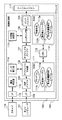
図1は実施例1の画像形成装置(以下「プリンタ」と呼ぶ)の構成例を示すブロック図である。
[Device configuration]
FIG. 1 is a block diagram illustrating a configuration example of an image forming apparatus (hereinafter referred to as “printer”) according to the first embodiment.
ホストコンピュータ101は、色、文字、図形、画像、印刷枚数などを示す、印刷処理を行うための印刷情報をプリンタ102に出力する。スキャナ116は、後述するパッチパターンを読み取り、その画像データをプリンタ102に出力する。
The
プリンタ102は、画像処理部103、および、画像処理部103から出力される画像信号に基づき画像を形成するプリンタエンジン117に大別される。
The
画像処理部103のCPU 112は、ROM 111に格納されたプログラムに従い、各種の処理、判断、および、後述する画像処理部103の構成を制御する。ROM 111には、後述する処理および制御用のプログラム111aのほか、後述する色変換テーブル111bおよび基本色濃度特性テーブル111cなどが格納されている。また、RAM 113には、CPU 112が各種の処理、判断、制御を行う際のプログラム、データ、ステータスなどが記憶される作業領域113aのほか、後述する濃度補正テーブル113bおよび基本色濃度補正テーブル113cを記憶する領域が割り当てられる。
The
ホストコンピュータ101から出力された印刷情報は、画像処理部103の、例えばネットワークインタフェイス、USB (Universal Serial Bus)やIEEE1394などのシリアルバスインタフェイスであるI/F 104に受信され、受信バッファ105に保持される。オブジェクト生成部106は、受信バッファ105から印刷情報を読み出し、色、文字、図形、画像などの情報を中間情報(以下「オブジェクト」と呼ぶ)に変換し、オブジェクトバッファ107に格納する。
The print information output from the
オブジェクト生成部106は、印刷情報をオブジェクトへ変換する際に、色変換テーブル111bを参照して、オブジェクトのデータを六色のトナーに対応する濃度レベルの色成分データCMYKおよびLC、LMに色分解する。さらに、印刷情報のグレーレベル設定、カラーレベル設定、多値画像など色に関連データは、データ補正部114に、基本色濃度補正テーブル113cを用いた後述する濃度レベルの補正、並びに、濃度補正テーブル113bを用いたガンマ補正を施させる。
When the print information is converted into an object, the
レンダリング部108は、オブジェクトバッファ107からオブジェクトを読み出しバンドバッファ109にバンド単位かつ色成分単位にビットマップイメージを描画する。その際、中間調処理部110に、中間調処理を行わせ、ビットマップイメージの階調数をプリンタエンジン117の出力階調数に落とす。
The
このようにして、バンドバッファ109にバンド単位かつ色成分単位に格納されたビットマップイメージは、プリンタエンジン117に出力され、記録媒体上にカラー画像が形成される。
In this way, the bitmap image stored in the
また、濃度補正部115は、USBやIEEE1394などのシリアルバスインタフェイスであるI/F 118を介して、スキャナ116に後述する階調パッチパターンを読み取らせ、その画像データを取得する。そして、各パッチの濃度値から濃度補正テーブル113bを作成し、濃度補正テーブル113bテーブルをRAM 113の所定領域に格納する。また、スキャナ116に後述する混色パッチパターンを読み取らせ、各パッチの濃度値と基本色濃度特性テーブル111cから基本色濃度補正テーブル113cを作成し、基本色濃度補正テーブル113cをRAM 113の所定領域に格納する。
In addition, the
[色変換テーブル]
図2は色変換テーブル111bを説明する図である。
[Color conversion table]
FIG. 2 is a diagram for explaining the color conversion table 111b.
色変換テーブル111bは、プリンタ102に入力されるRGB画像データと、六色のトナーに対応する色成分データCMYKおよびLC、LMを対応付けるテーブルである。色変換テーブル111bは、RGBデータに対して一定の間隔で出力値をもつRGB三次元ルックアップテーブル(3D LUT)である。なお、データ補正部114は、色変換テーブル111bに用意されていない入力値に対する出力値を、補間演算により、その入力値周辺の入力値に対応する出力値から求める。
The color conversion table 111b is a table that associates RGB image data input to the
図3は色変換テーブル111bから基本色のシアン(C)領域について色変換前後の濃度レベルを抽出した様子を示す図である。なお、色変換テーブル111bに入力されるRGBデータは輝度値を表すが、説明を簡単にするために、図3では入力濃度値と出力濃度値の関係を示すことにする。なお、このC、M、Y、K、LC、LMの六色を一次色とする。そして、シアン(C)とライトシアン(LC)とから構成される色を基本色として定義する(マゼンダ(M)とライトマゼンダ(LM)の混合によって構成される色も同様)。 FIG. 3 is a diagram illustrating a state in which density levels before and after color conversion are extracted from the color conversion table 111b for the cyan (C) region of the basic color. Note that the RGB data input to the color conversion table 111b represents a luminance value, but in order to simplify the explanation, FIG. 3 shows the relationship between the input density value and the output density value. The six colors C, M, Y, K, LC, and LM are primary colors. A color composed of cyan (C) and light cyan (LC) is defined as a basic color (the same is true for a color composed of a mixture of magenta (M) and light magenta (LM)).
図3に示すように、シアン(C)の入力濃度値が低い領域においては淡トナーのみを使用し、基準の濃度値(図3に示す基準値B)に達すると、濃トナーの使用を開始してシアン(C)領域を再現する。 As shown in Fig. 3, only light toner is used in the region where the input density value of cyan (C) is low, and when the standard density value (reference value B shown in Fig. 3) is reached, the use of dark toner is started. To reproduce the cyan (C) region.
なお、詳細は後述するが、実施例1の濃度補正を最大限に活用するために、濃トナーの使用は、まず、色変換テーブル111bにより基準値Aから開始し、その後、基準値Bから開始するように基本色濃度補正テーブル113cを作成する。 Although details will be described later, in order to make the most of the density correction of Example 1, the use of dark toner starts from the reference value A by the color conversion table 111b and then starts from the reference value B. Thus, the basic color density correction table 113c is created.
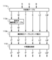
[色処理]
図4は画像処理部103が実行する色処理を説明する図である。
[Color processing]
FIG. 4 is a diagram for explaining color processing executed by the
入力画像データの各色信号値R、G、Bは、色変換テーブル111b(3D LUT)によりC、M、Y、K、LC、LMの六色の信号値に変換される。六色の信号値のうちCおよびMの二色の信号値が基本色濃度補正テーブル113c(1D LUT)で補正された後、六色の信号値C'、M'、Y、K、LC、LMは濃度補正テーブル113b(ガンマLUT)で補正される。そして、ガンマ補正された六色の信号C"、M"、Y'、K'、LC'、LM'は、中間調処理部110によってディザまたは誤差拡散処理が施され、階調数が落とされた信号値C'"、M'"、Y"、K"、LC"、LM"になる。
Each color signal value R, G, B of the input image data is converted into six color signal values of C, M, Y, K, LC, and LM by the color conversion table 111b (3D LUT). After the six color signal values C and M are corrected by the basic color density correction table 113c (1D LUT), the six color signal values C ′, M ′, Y, K, LC, LM is corrected by the density correction table 113b (gamma LUT). The six-color signals C ″, M ″, Y ′, K ′, LC ′, and LM ′ that have been gamma corrected are subjected to dithering or error diffusion processing by the
[階調パッチパターン]
図5は濃度補正テーブル113bを作成するための階調パッチパターンの一例を示す図である。
[Gradation patch pattern]
FIG. 5 is a diagram showing an example of a gradation patch pattern for creating the density correction table 113b.
階調パッチパターンは、LC、C、LM、M、Y、Kの各色の領域をもち、各領域には、濃度レベルが5%刻みのパッチを配置する。この階調パッチパターンは、ホストコンピュータ101のコマンドやプリンタ102のテストプリント機能により記録紙上に印刷される。つまり、濃度補正部115は、階調パッチパターンを読み取った画像データから一次色(C、M、Y、K、LC、LM)の階調特性を取得し、一次色の階調特性を線形にする濃度補正テーブル113bを作成する。なお、パッチの濃度刻みは5%に限らず、一次色の階調特性を取得するために充分な数のパッチを形成できる濃度刻みであればよい。
The gradation patch pattern has areas of each color of LC, C, LM, M, Y, and K, and patches each having a density level of 5% are arranged in each area. This gradation patch pattern is printed on a recording sheet by a command of the
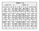
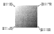
[混色パッチパタ−ン]
図6は基本色濃度特性テーブル111cを作成するための混色パッチパターンの一例を示す図、図7は濃淡トナーの混色率と濃度値の関係を示す基本色濃度特性テーブル111cの一例を示す図である。
[Mixed patch pattern]
FIG. 6 is a diagram showing an example of a color mixture patch pattern for creating the basic color density characteristic table 111c, and FIG. 7 is a diagram showing an example of the basic color density characteristic table 111c showing the relationship between the color mixture ratio of dark and light toner and the density value. is there.
混色パッチパターンは、基本色の淡トナーおよび濃トナーの濃度値(0〜100%)をそれぞれ17点抽出し、それら17点の単色と、それら17点の混色の組み合わせを記録紙に印刷したものである。予め、混色パッチパターンをスキャナ116(または測色機など)で測色して得た濃度値を二次元にマッピングすることで基本色濃度特性テーブル111cを得る。なお、混色パッチパターンおよび基本色濃度特性テーブル111cは、同じ色相の濃淡トナーの組み合わせそれぞれについて作成する必要がある。従って、実施例1の六色システムではC、LCの組み合わせ、M、LMの組み合わせについてそれぞれ作成するが、ライトイエロー(LY)を有する七色システムでは、さらにY、LYの組み合わせについて作成する。 The mixed color patch pattern is obtained by extracting 17 density values (0 to 100%) of the light and dark toners of the basic color and printing the 17 single colors and a combination of the 17 mixed colors on the recording paper. It is. The basic color density characteristic table 111c is obtained by two-dimensionally mapping density values obtained by measuring the color mixture patch pattern with the scanner 116 (or a colorimeter) in advance. The mixed color patch pattern and the basic color density characteristic table 111c need to be created for each combination of dark and light toners having the same hue. Accordingly, the combination of C and LC and the combination of M and LM are respectively created in the six-color system of the first embodiment, but the combination of Y and LY is further created in the seven-color system having light yellow (LY).
また、基本色濃度特性テーブル111cは任意の間隔で濃淡トナーの濃度値(入力値)をもつ。そのため、濃度補正部115は、用意されていない入力値に対する出力値を、線形補間により、その入力値近傍の入力値に対応する出力値から算出する。
The basic color density characteristic table 111c has density values (input values) of dark and light toner at arbitrary intervals. Therefore, the
図8は基本色濃度特性テーブル111cから、線形補間を用いて、濃度値0.4間隔の等濃度曲線を求めた図である。 FIG. 8 is a diagram in which an equal density curve with density value intervals of 0.4 is obtained from the basic color density characteristic table 111c using linear interpolation.
[キャリブレーション]
図9はプリンタ102のキャリブレーションを説明するフローチャートである。このフローは、画像処理部103のCPU 112が、ROM 111に格納されたプログラムを実行することによって実現される。
[Calibration]
FIG. 9 is a flowchart for explaining calibration of the
まず、ユーザからの指示などに基づき、図5に示す階調パッチパターンを印刷し(S801)、スキャナ116に階調パッチパターンを読み取らせる。これにより、パッチの濃度値を取得し(S802)、各パッチの濃度値を用いて、後述する濃度補正を行い(S803)、その後、後述する基本色濃度補正を行う(S804)。
First, based on an instruction from the user, the gradation patch pattern shown in FIG. 5 is printed (S801), and the
● 濃度補正
図10は濃度補正(S803)の詳細を示すフローチャートである。この処理もCPU 112によって実行される。
Density Correction FIG. 10 is a flowchart showing details of the density correction (S803). This process is also executed by the
各パッチの濃度値から、階調パッチパターン作成時の入力濃度レベルに対する濃度特性(階調特性)を図5に示す各色領域ごとに算出し(S901)、注目する階調特性が淡トナーのものか否かを判定し(S902)、淡トナーの場合は、最大濃度のパッチの濃度値が規定の濃度値以上か否かを判定し(S903)、規定濃度値以上の場合は後述する濃度補正2を、未満の場合は後述する濃度補正1を行う(S904)。また、注目する階調特性が濃トナーのものの場合は濃度補正1を行う(S904)。そして、ステップS905の判定により、階調パッチパターンのすべての色領域の階調特性について上記の処理を繰り返す。
Based on the density value of each patch, the density characteristics (gradation characteristics) with respect to the input density level when creating the gradation patch pattern are calculated for each color area shown in FIG. 5 (S901). (S902), in the case of light toner, it is determined whether or not the density value of the maximum density patch is equal to or higher than a specified density value (S903). If it is less than 2,
図11は濃トナーにおける濃度特性(図11(a))と濃度補正テーブル(図11(b))の一例を示す図である。また、図12は淡トナーにおける濃度特性(図12(a))と濃度補正テーブル(図12(b))の一例を示し、最大濃度のパッチの濃度値が規定濃度値を下回る場合を示している。また、図13は淡トナーにおける濃度特性(図13(a))と濃度補正テーブル(図13(b))の一例を示し、淡トナーの最大測定濃度値が規定濃度値を超える場合を示している。 FIG. 11 is a diagram showing an example of density characteristics (FIG. 11 (a)) and a density correction table (FIG. 11 (b)) for dark toner. FIG. 12 shows an example of density characteristics (FIG. 12 (a)) and density correction table (FIG. 12 (b)) for light toner, and shows the case where the density value of the maximum density patch is below the specified density value. Yes. FIG. 13 shows an example of density characteristics (FIG. 13 (a)) and density correction table (FIG. 13 (b)) for light toner, and shows a case where the maximum measured density value of light toner exceeds a specified density value. Yes.
なお、階調特性の測定結果は、記録紙表面の濃度、および、プリンタエンジン117内部の汚れによるトナーの付着により、通常、濃度値0から始まらずに、いわゆる下地の濃度から始まる。図11(a)、図12(a)および図13(a)は、この下地の濃度を補正した後の階調特性を示している。つまり、本実施例に示す階調特性はすべて、下地の濃度が補正されたものである。 Note that the measurement result of the gradation characteristics usually does not start from a density value of 0 due to the density of the recording paper surface and toner adhesion due to dirt inside the printer engine 117, but starts from the so-called background density. FIGS. 11 (a), 12 (a), and 13 (a) show the tone characteristics after correcting the background density. That is, all the gradation characteristics shown in this embodiment are obtained by correcting the background density.
図11から図13を参照して、濃度補正1と2を説明するが、図11と図12における濃度補正が濃度補正1であり、図13における濃度補正が濃度補正2である。
The
図11(a)に示す実線は濃トナーの階調特性の測定結果を示し、破線は規定の階調特性(リニアな特性)を示す。従って、実線で示す階調特性を破線で示すリニアな特性に補正するために、図11(b)に実線で示すような補正特性を有する濃度補正テーブル113bを作成する。 The solid line shown in FIG. 11 (a) shows the measurement result of the dark toner gradation characteristics, and the broken line shows the specified gradation characteristics (linear characteristics). Therefore, in order to correct the gradation characteristic indicated by the solid line to the linear characteristic indicated by the broken line, the density correction table 113b having the correction characteristic shown by the solid line in FIG. 11B is created.
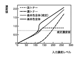
また、図12(a)に示す実線は淡トナーの階調特性の測定結果を示す。この場合、最大濃度のパッチの濃度値が規定濃度値に達しないため、再現可能な濃度値までを予め定めたリニアな特性にし、それ以降はフラットな特性にする、破線で示す階調特性を規定する。なお、上記リニアな部分を延長すると、点線で示すように、入力濃度レベル255で規定濃度値に達する。従って、実線で示す階調特性を破線で示す規定の階調特性に補正するために、図12(b)に実線で示すような補正特性を有する濃度補正テーブル113bを作成する。
Further, the solid line shown in FIG. 12 (a) shows the measurement result of the gradation characteristics of the light toner. In this case, since the density value of the patch having the maximum density does not reach the specified density value, the tone characteristic indicated by the broken line is set to a linear characteristic that is predetermined up to the reproducible density value and flat thereafter. Stipulate. When the linear portion is extended, the specified density value is reached at the
また、図13(a)に示す実線は淡トナーの階調特性の測定結果を示す。この場合、最大濃度のパッチの濃度値が規定濃度値を超えるため、階調特性が規定濃度値に達する入力濃度レベル(基準値C)までを予め定めたリニアな特性にし、基準値C以降は、最大濃度のパッチの濃度値へ向かう、破線で示す階調特性を規定する。なお、基準値C以前の上記リニアな部分を延長すると、点線で示すように、入力濃度レベル255で規定濃度値に達する。従って、実線で示す階調特性を破線で示す規定の階調特性に補正するために、図13(b)に実線で示すような補正特性を有する濃度補正テーブル113bを作成する。
Also, the solid line shown in FIG. 13 (a) shows the measurement result of the gradation characteristics of the light toner. In this case, since the density value of the maximum density patch exceeds the specified density value, the input density level (reference value C) at which the gradation characteristics reach the specified density value is set to a predetermined linear characteristic. The gradation characteristic indicated by a broken line toward the density value of the patch having the maximum density is defined. When the linear portion before the reference value C is extended, the specified density value is reached at the
● 基本色濃度補正
図14は基本色濃度補正(S804)の詳細を示すフローチャートである。このフローは画像処理部103のCPU 112が、ROM 111に格納されたプログラムを実行することによって実現される。
Basic Color Density Correction FIG. 14 is a flowchart showing details of basic color density correction (S804). This flow is realized by the
まず、色変換テーブル111bから色変換後の一次色領域の淡トナーおよび濃トナーの入力濃度レベルを得て、淡トナーおよび濃トナーの入力濃度レベルを濃度補正(S803)で作成した濃度補正テーブル113bに入力することで、一次色領域の淡トナーおよび濃トナーの出力濃度レベルを取得する(S1301、S1302)。 First, the input density levels of the light toner and the dark toner in the primary color area after color conversion are obtained from the color conversion table 111b, and the density correction table 113b created by the density correction (S803) for the input density levels of the light toner and the dark toner. To obtain the output density levels of the light toner and the dark toner in the primary color area (S1301, S1302).
次に、基本色濃度特性テーブル111cを参照して、一次色領域の淡トナーおよび濃トナーの出力濃度レベルから、淡トナーだけの領域から淡トナーおよび濃トナーの混色領域を含む基本色領域全体の階調特性を取得する(S1303)。これにより、濃淡トナーの混色領域を含む一次色全体の階調特性が得られる。 Next, referring to the basic color density characteristic table 111c, from the output density level of the light toner and the dark toner in the primary color area, the entire basic color area including the light toner and dark toner mixed color area from the area only of the light toner is determined. Gradation characteristics are acquired (S1303). Thereby, the gradation characteristics of the entire primary color including the mixed color region of the light and light toner can be obtained.
次に、基本色濃度特性テーブル111cを参照して、一次色全体の階調特性を後述する規定の一次色階調特性にする基本色濃度補正テーブル113cを作成する(S1304)。 Next, with reference to the basic color density characteristic table 111c, a basic color density correction table 113c is created that sets the gradation characteristics of the entire primary color to the prescribed primary color gradation characteristics described later (S1304).
次に、ステップS1305の判定により、同じ色相の淡トナーと濃トナーの組み合わせすべて(本実施例ではLCとCおよびLMとMの組み合わせ)について上記の処理を繰り返す。 Next, according to the determination in step S1305, the above processing is repeated for all combinations of light toner and dark toner having the same hue (in this embodiment, combinations of LC and C and LM and M).
図15から図17は一次色領域における濃淡トナーそれぞれの階調特性、濃淡トナーによって再現される一次色全体の階調特性、および、規定の一次色階調特性の一例を示す図である。また、図18は基本色濃度補正(S804)によって作成される基本色濃度補正テーブル113cの一例を示す図である。これらの図を用いて、基本色濃度補正を詳しく説明する。 FIGS. 15 to 17 are diagrams showing examples of tone characteristics of dark and light toners in the primary color region, tone characteristics of the entire primary color reproduced by the dark and light toner, and prescribed primary color tone characteristics. FIG. 18 is a diagram showing an example of a basic color density correction table 113c created by basic color density correction (S804). The basic color density correction will be described in detail with reference to these drawings.
図15は、濃度補正(S803)時に濃淡トナーともに規定の階調特性を示した場合の濃淡トナーそれぞれの階調特性、および、一次色全体の階調特性の一例を示している。 FIG. 15 shows an example of the gradation characteristics of each of the light and light toners and the gradation characteristics of the entire primary color when both the dark and light toners exhibit the specified gradation characteristics during the density correction (S803).
図15において、例えば、入力濃度レベルが120のとき、淡トナーの濃度値DLは0.70、濃トナーの濃度値Ddは0.25であり、基本色濃度特性テーブル111bを参照してDLおよびDdから算出される一次色全体の濃度値Dbは0.93、規定の一次色階調特性の濃度値Dbsは0.80である。この場合、DLを変えずに、DbがDbsに一致するように、基本色濃度特性テーブル111bを参照して濃トナーの濃度値Dd'(例えば0.10とする)を算出する。 15, for example, when the input density level is 120, the density value D L of the light toner is 0.70, the density value Dd of dark toner is 0.25, the D L and Dd with reference to basic color density characteristic table 111b The calculated density value Db of the entire primary color is 0.93, and the density value Dbs of the specified primary color gradation characteristic is 0.80. In this case, without changing the D L, Db is to match the Dbs, with reference to the basic color density characteristic table 111b calculating a dark toner density value Dd '(eg, 0.10).
次に、入力濃度レベルが120のときの濃トナーの信号レベル、つまり濃度値Dd=0.25を再現する信号レベルを、濃度値Dd'=0.10を再現するレベルに補正する。従って、図11(a)に実線で示す階調特性(実測値)のDd=0.25、Dd'=0.10に対応する濃度レベルを求め、当該濃度レベルを出力濃度レベルとして濃度補正テーブル113bから入力濃度レベルを求め、それらを補正前後の信号レベルとして、補正テーブルを作成する。 Next, the signal level of the dark toner when the input density level is 120, that is, the signal level that reproduces the density value Dd = 0.25 is corrected to the level that reproduces the density value Dd ′ = 0.10. Therefore, the density level corresponding to Dd = 0.25 and Dd ′ = 0.10 in the gradation characteristics (measured values) indicated by the solid line in FIG. 11A is obtained, and the input density is obtained from the density correction table 113b using the density level as the output density level. Levels are obtained and a correction table is created using them as signal levels before and after correction.
このような補正を一次色全体に行い、図18に示す(a)のような基本色濃度補正テーブル113cを作成すれば、図15に細線で示す規定の一次色階調特性を得ることができる。 By performing such correction on the entire primary color and creating a basic color density correction table 113c as shown in FIG. 18 (a), it is possible to obtain the prescribed primary color gradation characteristics shown by thin lines in FIG. .
図16に示す、濃度補正(S803)時に濃淡トナーの最大濃度が規定濃度値に満たない場合や、図17に示す、濃度補正(S803)時に濃淡トナーの最大濃度が規定濃度値を超える場合も、上記と同様の補正を一次色全体に行い、図18に示す(c)または(b)のような基本色濃度補正テーブル113cを作成すれば、図16または図17に細線で示す規定の一次色階調特性を得ることができる。 In the case where the maximum density of the dark and light toner does not reach the specified density value during density correction (S803) shown in FIG. 16 or in the case where the maximum density of the dark and light toner exceeds the specified density value during density correction (S803) shown in FIG. If the basic color density correction table 113c as shown in (c) or (b) of FIG. 18 is created by performing the same correction as described above on the entire primary color, the primary specified in the thin line in FIG. 16 or FIG. Color gradation characteristics can be obtained.
このように、六色システムにおいて上記のキャリブレーションを行い、各色成分信号にガンマ補正を施す前に、濃淡トナーの組み合わせを有する一次色の濃トナーに対応する色成分信号に基本色濃度補正テーブル113cにより階調補正を施すことで、中間濃度領域(混色領域)における濃度変動を抑えて、階調変化の不連続を防ぎ、擬似輪郭の発生を防ぐことができる。 Thus, before performing the above calibration in the six-color system and performing gamma correction on each color component signal, the basic color density correction table 113c is added to the color component signal corresponding to the dark toner of the primary color having a combination of dark and light toners. By performing the gradation correction according to the above, it is possible to suppress the density fluctuation in the intermediate density area (mixed color area), to prevent the discontinuity of the gradation change, and to prevent the generation of the pseudo contour.
さらに、一次色のパッチパターンの形成と、パッチ濃度の測定から構成される上記のキャリブレーションにより、一次色の混色領域の階調補正を行う。従って、少ない数のパッチパターンで済み、キャリブレーションに必要な時間、および、記録紙やトナーの消費量の増加を抑えることができる。 Further, gradation correction of the mixed color region of the primary color is performed by the calibration including the formation of the primary color patch pattern and the patch density measurement. Therefore, a small number of patch patterns are required, and the time required for calibration and the increase in consumption of recording paper and toner can be suppressed.
また、一次色のパッチ濃度だけから混色領域の階調補正が可能なキャリブレーションであるから、四色システムと同等のハードウェア構成に容易に実装可能で、四色システムのハードウェアを比較的容易に六色システムに拡張可能ある。 In addition, since it is a calibration that can correct the gradation of the mixed color area only from the patch density of the primary color, it can be easily implemented in a hardware configuration equivalent to the four-color system, and the hardware of the four-color system is relatively easy It can be extended to a six-color system.
以下、本発明にかかる実施例2の画像処理を説明する。なお、実施例2において、実施例1と略同様の構成については、同一符号を付して、その詳細説明を省略する。 The image processing according to the second embodiment of the present invention will be described below. Note that the same reference numerals in the second embodiment denote the same parts as in the first embodiment, and a detailed description thereof will be omitted.
実施例1においては、図4に示したように、基本色濃度補正テーブル113cと濃度補正テーブル113bを別テーブルとして作成して色処理を行った。しかし、これらテーブルはともに一次元ルックアップテーブルであるから、図19に示すステップS805でそれらテーブルを合成して一つのテーブル(例えば濃度補正テーブル113b)にする。そしてこの合成したテーブルを用いて、図20に示す色処理を行うことが可能である。 In the first embodiment, as shown in FIG. 4, the basic color density correction table 113c and the density correction table 113b are created as separate tables and color processing is performed. However, since these tables are both one-dimensional lookup tables, they are combined into one table (for example, the density correction table 113b) in step S805 shown in FIG. Then, it is possible to perform the color processing shown in FIG. 20 using this synthesized table.
図21は基本色濃度補正テーブル113cが合成された濃度補正テーブル113bの一例を示す図で、(a)はステップS803で作成した濃度補正テーブル113b、(b)はステップS804で作成した基本色濃度補正テーブル113c、(c)は合成後の濃度補正テーブル113cである。 FIG. 21 is a diagram showing an example of a density correction table 113b obtained by combining the basic color density correction table 113c. (A) is a density correction table 113b created in step S803, and (b) is a basic color density created in step S804. The correction tables 113c and (c) are the density correction table 113c after synthesis.
ある入力濃度レベルiにおける、濃度補正テーブル113bの補正濃度レベルをDiとし、基本色濃度補正テーブル113cの補正濃度レベルをSDiとすると、入力濃度レベルiにおける合成後の濃度補正テーブル113bの補正濃度レベルDi'は下式で表される。
Di' = SDDi
When the correction density level of the density correction table 113b at a certain input density level i is Di and the correction density level of the basic color density correction table 113c is SDi, the correction density level of the density correction table 113b after combination at the input density level i Di 'is represented by the following formula.
Di '= SD Di
[変形例]
以上の説明では、濃淡トナーとする一次色をシアンおよびマゼンダとしたが、これに限定されるわけではなく、イエローやブラックについても、同一の色相で、かつ、明度が異なるトナーを用いる場合は、上記の階調補正、濃度補正を同様に適用することができる。
[Modification]
In the above description, the primary colors used for the light and light toners are cyan and magenta. However, the present invention is not limited to this. For yellow and black, when toners having the same hue and different lightness are used, The above gradation correction and density correction can be applied in the same manner.
また、入力画像信号がRGB輝度信号の例を説明したが、CMY(またはCMYK)濃度信号が入力される場合も、上記の階調補正、濃度補正を同様に適用することができる。 Further, although an example in which the input image signal is an RGB luminance signal has been described, the above-described gradation correction and density correction can be similarly applied when a CMY (or CMYK) density signal is input.
また、テーブルに保持されていない出力値、線形補間すると説明したが、線形補間法に限定されるものではなく、スプライン補間法などの他の補間法を用いてもよい。 Further, the output values not held in the table and linear interpolation have been described, but the present invention is not limited to the linear interpolation method, and other interpolation methods such as a spline interpolation method may be used.
また、上記では、カラープリンタにおけるキャリブレーションを説明したが、カラー複写機やカラー複合機のキャリブレーションにも適用可能であるである。 In the above description, the calibration in the color printer has been described. However, the present invention can also be applied to the calibration of a color copying machine or a color complex machine.
また、上記では、色材としてトナーを用いる電子写真方式のプリンタのキャリブレーションを説明したが、顔料や染料系のインクなどを用いる画像形成装置にも有効である。 In the above description, calibration of an electrophotographic printer using toner as a color material has been described. However, the present invention is also effective for an image forming apparatus using pigment or dye-based ink.
また、上記では、濃度補正および基本色濃度補正のターゲットである規定の階調特性はリニアな特性と説明したが、曲線であってもよい。 In the above description, the prescribed gradation characteristics that are targets of density correction and basic color density correction are described as linear characteristics, but may be curves.
[他の実施例]
なお、本発明は、複数の機器(例えばホストコンピュータ、インタフェイス機器、リーダ、プリンタなど)から構成されるシステムに適用しても、一つの機器からなる装置(例えば、複写機、ファクシミリ装置など)に適用してもよい。
[Other embodiments]
Note that the present invention can be applied to a system including a plurality of devices (for example, a host computer, an interface device, a reader, and a printer), and a device (for example, a copying machine and a facsimile device) including a single device. You may apply to.
また、本発明の目的は、前述した実施例の機能を実現するソフトウェアのプログラムコードを記録した記憶媒体(または記録媒体)を、システムあるいは装置に供給し、そのシステムあるいは装置のコンピュータ(またはCPUやMPU)が記憶媒体に格納されたプログラムコードを読み出し実行することによっても、達成されることは言うまでもない。この場合、記憶媒体から読み出されたプログラムコード自体が前述した実施例の機能を実現することになり、そのプログラムコードを記憶した記憶媒体は本発明を構成することになる。また、コンピュータが読み出したプログラムコードを実行することにより、前述した実施例の機能が実現されるだけでなく、そのプログラムコードの指示に基づき、コンピュータ上で稼働しているオペレーティングシステム(OS)などが実際の処理の一部または全部を行い、その処理によって前述した実施例の機能が実現される場合も含まれることは言うまでもない。 Also, an object of the present invention is to supply a storage medium (or recording medium) on which a program code of software that realizes the functions of the above-described embodiments is recorded to a system or apparatus, and the computer (or CPU or CPU) of the system or apparatus. Needless to say, this can also be achieved by the MPU) reading and executing the program code stored in the storage medium. In this case, the program code itself read from the storage medium realizes the functions of the above-described embodiments, and the storage medium storing the program code constitutes the present invention. Further, by executing the program code read by the computer, not only the functions of the above-described embodiments are realized, but also an operating system (OS) running on the computer based on the instruction of the program code. It goes without saying that a case where the function of the above-described embodiment is realized by performing part or all of the actual processing and the processing is included.
さらに、記憶媒体から読み出されたプログラムコードが、コンピュータに挿入された機能拡張カードやコンピュータに接続された機能拡張ユニットに備わるメモリに書込まれた後、そのプログラムコードの指示に基づき、その機能拡張カードや機能拡張ユニットに備わるCPUなどが実際の処理の一部または全部を行い、その処理によって前述した実施例の機能が実現される場合も含まれることは言うまでもない。 Furthermore, after the program code read from the storage medium is written into a memory provided in a function expansion card inserted into the computer or a function expansion unit connected to the computer, the function is determined based on the instruction of the program code. Needless to say, the CPU of the expansion card or the function expansion unit performs part or all of the actual processing and the functions of the above-described embodiments are realized by the processing.
本発明を上記記憶媒体に適用する場合、その記憶媒体には、先に説明したフローチャートに対応するプログラムコードが格納されることになる。 When the present invention is applied to the storage medium, the storage medium stores program codes corresponding to the flowcharts described above.
Claims (2)
前記複数の信号値それぞれに対応する記録材により記録媒体上に画像を形成する形成手段と、
基本色濃度補正テーブルを使用して、前記複数の信号値に含まれる前記濃色の信号値を補正する濃度補正手段と、
前記補正された濃色の信号値および前記複数の信号値に含まれる前記濃色以外の信号値を入力し、濃度補正テーブルを使用して前記入力した信号値をガンマ補正し、前記ガンマ補正した信号値を前記形成手段に出力するガンマ補正手段と、
前記複数の信号値をそれぞれ変化させて前記形成手段に供給し、前記記録材によって、複数のパッチを有するパッチパターンを記録媒体に形成させるパッチパターン生成手段と、
前記複数のパッチの濃度を測定する測定手段と、
前記測定手段の測定結果に基づき前記濃度補正テーブルを生成する第一の生成手段と、
前記測定手段の測定結果に基づき前記基本色濃度補正テーブルを生成する第二の生成手段とを有し、
前記濃色または前記淡色の信号値がゼロに対応するパッチは前記淡記録材または前記濃記録材のみによって形成され、
前記第一の生成手段は、前記淡色の信号値がゼロに対応するパッチの前記測定された濃度と、前記濃色の信号値の関係から前記濃色の信号値の補正に使用する濃度補正テーブルを生成する手段と、
前記濃色の信号値がゼロに対応し、前記淡色の信号値が最大の、所定パッチの前記測定された濃度が規定濃度以上か否かを判定する手段と、
前記所定パッチの前記測定された濃度が前記規定濃度未満の場合は、最大濃度に対応すべき所定の信号値を前記最大濃度を再現する信号値に補正し、前記所定の信号値未満の信号値を濃度ゼロと前記最大濃度を結ぶ線分上の濃度を再現する信号値に補正し、前記所定の信号値超の信号値を前記最大濃度を再現する信号値に補正する特性を有する前記淡色の信号値の補正に使用する濃度補正テーブルを生成し、前記所定パッチの前記測定された濃度が前記規定濃度以上の場合は、前記規定濃度以下の信号値を前記濃度ゼロと前記規定濃度を結ぶ線分上の濃度を再現する信号値に補正し、前記規定濃度超の信号値を前記規定濃度と前記最大濃度を結ぶ線分上の濃度を再現する信号値に補正する特性を有する淡色の信号値の補正に使用する濃度補正テーブルを生成する手段とを有し、
前記第二の生成手段は、前記変換手段の変換特性および前記濃度補正テーブルから、前記濃色の信号値と前記濃記録材が形成する画像の濃度の関係を示す濃度特性、および、前記淡色の信号値と前記淡記録材が形成する画像の濃度の関係を示す濃度特性を取得する手段と、
前記測定結果から前記濃記録材と前記淡記録材が混色した画像の濃度を示す基本色濃度特性テーブルを生成し、前記変換手段の変換特性および前記基本色濃度特性テーブルから前記濃色の記録材と前記淡色の記録材が形成する一次色全体の階調特性を取得する手段と、
前記濃度特性および前記一次色全体の階調特性に基づき、前記一次色全体の階調特性を規定の階調特性にするように前記濃色の信号値を補正する前記基本色濃度補正テーブルを生成する手段とを有することを特徴とする画像処理装置。 Conversion means for converting the color signal value of the input image data into a plurality of signal values including a dark signal value corresponding to a dark recording material of the same hue and a light signal value corresponding to a light recording material;
Forming means for forming an image on a recording medium with a recording material corresponding to each of the plurality of signal values;
Using a basic color density correction table, density correction means for correcting the dark color signal values included in the plurality of signal values;
The corrected dark signal value and a signal value other than the dark color included in the plurality of signal values are input, the input signal value is gamma-corrected using a density correction table, and the gamma correction is performed. Gamma correction means for outputting a signal value to the forming means;
Patch pattern generating means for changing the plurality of signal values to supply to the forming means and forming a patch pattern having a plurality of patches on the recording medium by the recording material;
Measuring means for measuring the density of the plurality of patches;
First generation means for generating the density correction table based on the measurement result of the measurement means;
Second generating means for generating the basic color density correction table based on the measurement result of the measuring means;
The patch corresponding to the dark color or the light signal value of zero is formed only by the light recording material or the dark recording material,
The first generation means includes a density correction table used for correcting the dark signal value based on a relationship between the measured density of the patch corresponding to the light signal value of zero and the dark signal value. Means for generating
Means for determining whether the measured density of a predetermined patch is equal to or higher than a specified density, wherein the dark signal value corresponds to zero and the light signal value is maximum;
When the measured density of the predetermined patch is less than the specified density, a predetermined signal value that should correspond to the maximum density is corrected to a signal value that reproduces the maximum density, and a signal value that is less than the predetermined signal value Is corrected to a signal value that reproduces the density on a line segment connecting the density zero and the maximum density, and the signal value of the light color having the characteristic of correcting a signal value exceeding the predetermined signal value to a signal value that reproduces the maximum density is corrected. A density correction table used for correcting the signal value is generated, and when the measured density of the predetermined patch is equal to or higher than the specified density, a signal value equal to or lower than the specified density is connected to the density zero and the specified density. A light signal value having a characteristic of correcting a signal value that reproduces the density on the minute to a signal value that reproduces the signal value exceeding the specified density on the line segment that connects the specified density and the maximum density Density correction used for image correction And means for generating a Buru,
The second generation unit is configured to convert a density characteristic indicating a relationship between the dark color signal value and an image density formed by the dark recording material from the conversion characteristic of the conversion unit and the density correction table, and the light color Means for acquiring a density characteristic indicating a relationship between a signal value and a density of an image formed by the light recording material;
Based on the measurement result, a basic color density characteristic table indicating the density of an image in which the dark recording material and the light recording material are mixed is generated, and the dark color recording material is obtained from the conversion characteristics of the converting means and the basic color density characteristic table. And means for acquiring gradation characteristics of the entire primary color formed by the light-color recording material;
Based on the density characteristic and the gradation characteristic of the entire primary color, the basic color density correction table for correcting the dark color signal value so that the gradation characteristic of the entire primary color becomes a specified gradation characteristic is generated. And an image processing apparatus.
基本色濃度補正テーブルを使用して、前記複数の信号値に含まれる前記濃色の信号値を補正する濃度補正ステップと、
前記補正された濃色の信号値および前記複数の信号値に含まれる前記濃色以外の信号値を入力し、濃度補正テーブルを使用して前記入力した信号値をガンマ補正し、前記ガンマ補正した信号値を前記形成手段に出力するガンマ補正ステップと、
前記複数の信号値をそれぞれ変化させて前記形成手段に供給し、前記記録材によって、複数のパッチを有するパッチパターンを記録媒体に形成させるパッチパターン生成ステップと、
前記複数のパッチの濃度を測定する測定ステップと、
前記測定ステップの測定結果に基づき前記濃度補正テーブルを生成する第一の生成ステップと、
前記測定ステップの測定結果に基づき前記基本色濃度補正テーブルを生成する第二の生成ステップとを有し、
前記濃色または前記淡色の信号値がゼロに対応するパッチは前記淡記録材または前記濃記録材のみによって形成され、
前記第一の生成ステップは、前記淡色の信号値がゼロに対応するパッチの前記測定された濃度と、前記濃色の信号値の関係から前記濃色の信号値の補正に使用する濃度補正テーブルを生成するステップと、
前記濃色の信号値がゼロに対応し、前記淡色の信号値が最大の、所定パッチの前記測定された濃度が規定濃度以上か否かを判定するステップと、
前記所定パッチの前記測定された濃度が前記規定濃度未満の場合は、最大濃度に対応すべき所定の信号値を前記最大濃度を再現する信号値に補正し、前記所定の信号値未満の信号値を濃度ゼロと前記最大濃度を結ぶ線分上の濃度を再現する信号値に補正し、前記所定の信号値超の信号値を前記最大濃度を再現する信号値に補正する特性を有する前記淡色の信号値の補正に使用する濃度補正テーブルを生成し、前記所定パッチの前記測定された濃度が前記規定濃度以上の場合は、前記規定濃度以下の信号値を前記濃度ゼロと前記規定濃度を結ぶ線分上の濃度を再現する信号値に補正し、前記規定濃度超の信号値を前記規定濃度と前記最大濃度を結ぶ線分上の濃度を再現する信号値に補正する特性を有する淡色の信号値の補正に使用する濃度補正テーブルを生成するステップとを有し、
前記第二の生成ステップは、前記変換手段の変換特性および前記濃度補正テーブルから、前記濃色の信号値と前記濃記録材が形成する画像の濃度の関係を示す濃度特性、および、前記淡色の信号値と前記淡記録材が形成する画像の濃度の関係を示す濃度特性を取得するステップと、
前記測定結果から前記濃記録材と前記淡記録材が混色した画像の濃度を示す基本色濃度特性テーブルを生成し、前記変換手段の変換特性および前記基本色濃度特性テーブルから前記濃色の記録材と前記淡色の記録材が形成する一次色全体の階調特性を取得するステップと、
前記濃度特性および前記一次色全体の階調特性に基づき、前記一次色全体の階調特性を規定の階調特性にするように前記濃色の信号値を補正する前記基本色濃度補正テーブルを生成するステップとを有することを特徴とする画像処理方法。 Conversion means for converting color signal values of input image data into a plurality of signal values including a dark signal value corresponding to a dark recording material of the same hue and a light signal value corresponding to a light recording material; An image processing method of an image processing apparatus having a forming unit that forms an image on a recording medium with a light recording material corresponding to each of the signal values of:
A density correction step of correcting the dark color signal values included in the plurality of signal values using a basic color density correction table;
The corrected dark signal value and a signal value other than the dark color included in the plurality of signal values are input, the input signal value is gamma-corrected using a density correction table, and the gamma correction is performed. A gamma correction step of outputting a signal value to the forming means;
A patch pattern generating step of changing the plurality of signal values to supply to the forming unit and forming a patch pattern having a plurality of patches on a recording medium by the recording material;
A measuring step for measuring the density of the plurality of patches;
A first generation step of generating the density correction table based on the measurement result of the measurement step;
A second generation step of generating the basic color density correction table based on the measurement result of the measurement step;
The patch corresponding to the dark color or the light signal value of zero is formed only by the light recording material or the dark recording material,
The first generation step includes a density correction table used for correcting the dark signal value based on a relationship between the measured density of the patch corresponding to the light signal value of zero and the dark signal value. A step of generating
Determining whether the measured density of a given patch is greater than or equal to a specified density, the dark color signal value corresponding to zero and the light color signal value being maximum;
When the measured density of the predetermined patch is less than the specified density, a predetermined signal value that should correspond to the maximum density is corrected to a signal value that reproduces the maximum density, and a signal value that is less than the predetermined signal value Is corrected to a signal value that reproduces the density on a line segment connecting the density zero and the maximum density, and the signal value of the light color having the characteristic of correcting a signal value exceeding the predetermined signal value to a signal value that reproduces the maximum density is corrected. A density correction table used for correcting the signal value is generated, and when the measured density of the predetermined patch is equal to or higher than the specified density, a signal value equal to or lower than the specified density is connected to the density zero and the specified density. A light signal value having a characteristic of correcting a signal value that reproduces the density on the minute to a signal value that reproduces the signal value exceeding the specified density on the line segment that connects the specified density and the maximum density Density correction used for image correction And a step of generating a Buru,
In the second generation step, from the conversion characteristic of the conversion unit and the density correction table, a density characteristic indicating a relationship between the dark signal value and the density of an image formed by the dark recording material, and the light color Acquiring a density characteristic indicating a relationship between a signal value and a density of an image formed by the light recording material;
Based on the measurement result, a basic color density characteristic table indicating the density of an image in which the dark recording material and the light recording material are mixed is generated, and the dark color recording material is obtained from the conversion characteristics of the converting means and the basic color density characteristic table. Acquiring gradation characteristics of the entire primary color formed by the light-color recording material;
Based on the density characteristic and the gradation characteristic of the entire primary color, the basic color density correction table for correcting the dark color signal value so that the gradation characteristic of the entire primary color becomes a specified gradation characteristic is generated. And an image processing method.
Priority Applications (3)
| Application Number | Priority Date | Filing Date | Title |
|---|---|---|---|
| JP2004275030A JP4393328B2 (en) | 2004-09-22 | 2004-09-22 | Image processing apparatus and method |
| US11/229,801 US20060061840A1 (en) | 2004-09-22 | 2005-09-20 | Image processing apparatus, its calibration method, and image processing method |
| CN200510106381.2A CN1758152B (en) | 2004-09-22 | 2005-09-22 | Image processing apparatus, its calibration method, and image processing method |
Applications Claiming Priority (1)
| Application Number | Priority Date | Filing Date | Title |
|---|---|---|---|
| JP2004275030A JP4393328B2 (en) | 2004-09-22 | 2004-09-22 | Image processing apparatus and method |
Publications (3)
| Publication Number | Publication Date |
|---|---|
| JP2006093957A JP2006093957A (en) | 2006-04-06 |
| JP2006093957A5 JP2006093957A5 (en) | 2007-09-06 |
| JP4393328B2 true JP4393328B2 (en) | 2010-01-06 |
Family
ID=36073640
Family Applications (1)
| Application Number | Title | Priority Date | Filing Date |
|---|---|---|---|
| JP2004275030A Expired - Fee Related JP4393328B2 (en) | 2004-09-22 | 2004-09-22 | Image processing apparatus and method |
Country Status (3)
| Country | Link |
|---|---|
| US (1) | US20060061840A1 (en) |
| JP (1) | JP4393328B2 (en) |
| CN (1) | CN1758152B (en) |
Families Citing this family (19)
| Publication number | Priority date | Publication date | Assignee | Title |
|---|---|---|---|---|
| JP4380602B2 (en) * | 2005-07-27 | 2009-12-09 | キヤノン株式会社 | Image forming apparatus and control method thereof |
| JP2007060149A (en) * | 2005-08-23 | 2007-03-08 | Canon Inc | Image processor and its method |
| JP4544109B2 (en) * | 2005-09-16 | 2010-09-15 | 富士ゼロックス株式会社 | Image processing apparatus and program |
| US8040365B2 (en) * | 2006-12-20 | 2011-10-18 | Samsung Electronics Co., Ltd. | Image forming apparatus and control method thereof |
| JP5415729B2 (en) * | 2007-09-10 | 2014-02-12 | キヤノン株式会社 | Image processing method and image processing apparatus |
| JP4974113B2 (en) * | 2007-12-06 | 2012-07-11 | 京セラドキュメントソリューションズ株式会社 | Calibration apparatus, calibration method, and calibration program |
| JP5018511B2 (en) * | 2008-01-30 | 2012-09-05 | セイコーエプソン株式会社 | Printer and control method thereof |
| JP2009212831A (en) * | 2008-03-04 | 2009-09-17 | Seiko Epson Corp | Test chart and color calibration method |
| JP5149690B2 (en) * | 2008-05-02 | 2013-02-20 | キヤノン株式会社 | Image processing apparatus, image processing method, and image processing program |
| JP5180670B2 (en) * | 2008-05-07 | 2013-04-10 | キヤノン株式会社 | Image processing apparatus and image processing method |
| JP5087527B2 (en) * | 2008-11-28 | 2012-12-05 | 京セラドキュメントソリューションズ株式会社 | Calibration apparatus, calibration method, and calibration program |
| JP5765912B2 (en) | 2010-10-07 | 2015-08-19 | キヤノン株式会社 | Image processing apparatus, image processing method, and program |
| JP2012150275A (en) * | 2011-01-19 | 2012-08-09 | Ricoh Co Ltd | Image processing device |
| CN102975502B (en) * | 2011-09-05 | 2016-12-21 | 北大方正集团有限公司 | Printer calibration steps and device for color management |
| JP6379794B2 (en) * | 2014-07-24 | 2018-08-29 | 株式会社リコー | Image processing apparatus, image processing method, and image processing system |
| US9531918B2 (en) * | 2014-12-30 | 2016-12-27 | Konica Minolta Laboratory U.S.A., Inc. | Scan calibration method that eliminates the color inaccuracy of printed color charts used on scan calibrations |
| CN104908440B (en) * | 2015-06-04 | 2017-03-22 | 中山火炬职业技术学院 | Sampling color card for ICC production of ceramic inkjet printing machine |
| JP6308398B2 (en) * | 2015-06-25 | 2018-04-11 | 京セラドキュメントソリューションズ株式会社 | Image forming apparatus and calibration program |
| CN110211191B (en) * | 2019-05-31 | 2021-02-05 | 广州市雅江光电设备有限公司 | Mixed color correction method and device, terminal equipment and readable storage medium |
Family Cites Families (13)
| Publication number | Priority date | Publication date | Assignee | Title |
|---|---|---|---|---|
| KR100265762B1 (en) * | 1997-12-29 | 2000-09-15 | 윤종용 | Apparatus and method for digitally compensating non-linearity of non-linear system, using piecewise linear method |
| US6542259B1 (en) * | 1999-02-23 | 2003-04-01 | Hewlett-Packard Company | Imaging system with color corrected light source |
| JP2001047665A (en) * | 1999-05-28 | 2001-02-20 | Canon Inc | Method and apparatus for processing image, and recording medium |
| US6832825B1 (en) * | 1999-10-05 | 2004-12-21 | Canon Kabushiki Kaisha | Test pattern printing method, information processing apparatus, printing apparatus and density variation correction method |
| JP4218164B2 (en) * | 2000-01-12 | 2009-02-04 | ブラザー工業株式会社 | Image recording method and recording medium recording image recording processing program |
| JP4218166B2 (en) * | 2000-01-21 | 2009-02-04 | ブラザー工業株式会社 | Computer-readable recording medium on which profile creation method and profile creation program are recorded |
| JP3559753B2 (en) * | 2000-07-17 | 2004-09-02 | キヤノン株式会社 | INK JET RECORDING APPARATUS AND CONTROL METHOD OF THE APPARATUS |
| US6435657B1 (en) * | 2001-08-20 | 2002-08-20 | Eastman Kodak Company | Method for multicolorant printing of digital images using reduced colorant amounts |
| EP1445941A4 (en) * | 2001-11-13 | 2006-09-20 | Seiko Epson Corp | Color conversion device, color conversion method, color change program and recording medium |
| JP2003170617A (en) * | 2001-12-07 | 2003-06-17 | Brother Ind Ltd | Distribution curve generating unit and program thereof |
| US7032989B2 (en) * | 2002-07-31 | 2006-04-25 | Canon Kabushiki Kaisha | Image processing method and image processing apparatus |
| US20040227967A1 (en) * | 2003-05-14 | 2004-11-18 | Marc Mahy | System and method for calibrating a printing device having light and heavy inks |
| US7656561B2 (en) * | 2004-05-31 | 2010-02-02 | Phase One A/S | Image compression for rapid high-quality imaging |
-
2004
- 2004-09-22 JP JP2004275030A patent/JP4393328B2/en not_active Expired - Fee Related
-
2005
- 2005-09-20 US US11/229,801 patent/US20060061840A1/en not_active Abandoned
- 2005-09-22 CN CN200510106381.2A patent/CN1758152B/en not_active Expired - Fee Related
Also Published As
| Publication number | Publication date |
|---|---|
| CN1758152A (en) | 2006-04-12 |
| JP2006093957A (en) | 2006-04-06 |
| CN1758152B (en) | 2011-06-01 |
| US20060061840A1 (en) | 2006-03-23 |
Similar Documents
| Publication | Publication Date | Title |
|---|---|---|
| JP4393328B2 (en) | Image processing apparatus and method | |
| US7755795B2 (en) | Color conversion method and profile generation method | |
| JP4656002B2 (en) | Image processing apparatus and image processing method | |
| JP3787534B2 (en) | Image processing apparatus, image processing method, and image processing program | |
| JP4974853B2 (en) | Image processing apparatus, image processing method, and program | |
| JP5300418B2 (en) | Image forming apparatus | |
| JP2004023740A (en) | Data processing apparatus and method, and image processing apparatus | |
| JPH11136532A (en) | Color image forming device and its control method | |
| US20020176104A1 (en) | Image processing apparatus, image forming apparatus, image processing method, and program product thereof | |
| JP2009083460A (en) | Color printing control device, color printing control method, and color printing control program | |
| JP2004058624A (en) | Image processing method and image processor | |
| JP2006238024A (en) | Image processor, image processing method and program, and recording medium | |
| JPH0823451A (en) | Method for deciding density data of color material | |
| JP4756388B2 (en) | Image processing apparatus, image forming apparatus, and image processing program | |
| US20100085617A1 (en) | Image Processing Apparatus and Image Recording Medium | |
| JP2006086969A (en) | Image processing apparatus, method thereof and storage medium | |
| JP2011151491A (en) | Device and program for color conversion | |
| JP2004289200A (en) | Image forming apparatus and image forming method | |
| JP2007336007A (en) | Color processing apparatus and method thereof | |
| JP2004064358A (en) | Image processing method and its apparatus | |
| JPH10224648A (en) | Picture processor and picture processing method | |
| JP3243397B2 (en) | Color image processing equipment | |
| JP5776379B2 (en) | Image forming apparatus and image forming method | |
| JP2015149635A (en) | image forming apparatus | |
| JP2008042273A (en) | Image forming apparatus and image forming method |
Legal Events
| Date | Code | Title | Description |
|---|---|---|---|
| A521 | Request for written amendment filed |
Free format text: JAPANESE INTERMEDIATE CODE: A523 Effective date: 20070720 |
|
| A621 | Written request for application examination |
Free format text: JAPANESE INTERMEDIATE CODE: A621 Effective date: 20070720 |
|
| RD03 | Notification of appointment of power of attorney |
Free format text: JAPANESE INTERMEDIATE CODE: A7423 Effective date: 20070720 |
|
| A977 | Report on retrieval |
Free format text: JAPANESE INTERMEDIATE CODE: A971007 Effective date: 20090310 |
|
| A131 | Notification of reasons for refusal |
Free format text: JAPANESE INTERMEDIATE CODE: A131 Effective date: 20090403 |
|
| A521 | Request for written amendment filed |
Free format text: JAPANESE INTERMEDIATE CODE: A523 Effective date: 20090421 |
|
| TRDD | Decision of grant or rejection written | ||
| A01 | Written decision to grant a patent or to grant a registration (utility model) |
Free format text: JAPANESE INTERMEDIATE CODE: A01 Effective date: 20091009 |
|
| A01 | Written decision to grant a patent or to grant a registration (utility model) |
Free format text: JAPANESE INTERMEDIATE CODE: A01 |
|
| A61 | First payment of annual fees (during grant procedure) |
Free format text: JAPANESE INTERMEDIATE CODE: A61 Effective date: 20091013 |
|
| R150 | Certificate of patent or registration of utility model |
Free format text: JAPANESE INTERMEDIATE CODE: R150 |
|
| FPAY | Renewal fee payment (event date is renewal date of database) |
Free format text: PAYMENT UNTIL: 20121023 Year of fee payment: 3 |
|
| FPAY | Renewal fee payment (event date is renewal date of database) |
Free format text: PAYMENT UNTIL: 20131023 Year of fee payment: 4 |
|
| LAPS | Cancellation because of no payment of annual fees |