JP4389345B2 - Drain cock drive device - Google Patents
Drain cock drive device Download PDFInfo
- Publication number
- JP4389345B2 JP4389345B2 JP2000127098A JP2000127098A JP4389345B2 JP 4389345 B2 JP4389345 B2 JP 4389345B2 JP 2000127098 A JP2000127098 A JP 2000127098A JP 2000127098 A JP2000127098 A JP 2000127098A JP 4389345 B2 JP4389345 B2 JP 4389345B2
- Authority
- JP
- Japan
- Prior art keywords
- drive
- drain plug
- drive source
- control board
- stepping motor
- Prior art date
- Legal status (The legal status is an assumption and is not a legal conclusion. Google has not performed a legal analysis and makes no representation as to the accuracy of the status listed.)
- Expired - Fee Related
Links
Images


Description
【0001】
【発明の属する技術分野】
本発明は、浴槽に付設される排水栓の開閉を電動で行う排水栓の駆動装置に関する。
【0002】
【従来の技術】
浴槽に付設される排水栓の開閉を電動で行う従来の排水栓装置として、例えば、図6に示される特開平10−212747号公報に記載のものがある。
【0003】
この排水栓装置では、図示しない電動操作スイッチが開閉操作されると、この操作信号が、制御部(図示せず)に入力され、制御部がステッピングモータ50を駆動することにより回転軸51およびカム52を偏心回転させて支持筒53が下降し、ワイヤ54を介して排水栓55を昇降させて開閉するものである。なお、56は手動で排水栓を開閉するための手動操作ボタンである。
【0004】
【発明が解決しようとする課題】
このような従来例では、排水栓を電動で開閉するための駆動源であるステッピングモータ50が、円筒形のケース57の外方に付設されるとともに、該ステッピングモータ50の回転軸51の回転運動を、円板上のカム52や支持筒53などを介して前記回転軸51と垂直なワイヤ54の軸線方向の運動に変換する構成であるために、大きなサイズとならざるを得ないという難点がある。
【0005】
また、ステッピングモータ50の動作を制御する制御部は、該ステッピングモータ50等の駆動部とは別のユニットとして別途配設されるものであり、このため、設置施工やメンテナンスが面倒であるといった難点もある。
【0006】
本発明は、上述の点に鑑みて為されたものであって、排水栓の駆動装置の小型化を図ることを主たる目的とし、さらには、その設置施工性やメンテナンス性を向上させることも目的とする。
【0007】
【課題を解決するための手段】
本発明では、上述の目的を達成するために、次のように構成している。
【0008】
すなわち、請求項1に係る本発明の排水栓の駆動装置は、浴槽の排水栓を、動力伝達部材を介して開閉駆動する駆動源と、この駆動源の動作を制御する駆動制御手段とを備え、前記駆動制御手段に与えられる制御信号に基づいて前記排水栓を開閉する排水栓の駆動装置において、前記駆動源は、その駆動軸が前記動力伝達部材の駆動源側の端部の軸線に沿うように配置され、前記駆動制御手段を構成する制御基板を、前記駆動軸が下方に延出する駆動源に隣接して配設するとともに、該制御基板に、前記制御信号を出力する操作スイッチを接続し、前記駆動源、前記制御基板および前記操作スイッチが、ケースに内装されて水密構造とされ、浴槽フランジ部または浴槽周辺部に組付けられるとともに、前記ケースが、組付け面から着脱自在とされるものである。
【0009】
請求項2に係る本発明は、請求項1の発明において、前記動力伝達部材がワイヤであり、前記駆動源は、ステッピングモータを備え、該ステッピングモータの回転動力が、前記軸線に沿う直線運動に変換されて前記ワイヤの駆動源側の端部に与えられるものである。
【0012】
請求項3に係る本発明は、請求項1または2の発明において、前記浴槽の給湯源となる給湯器から当該排水栓の駆動装置の電源が供給されるとともに、該電源に重畳されて前記駆動制御手段に対する遠隔操作用の前記制御信号が与えられるものである。
【0013】
請求項1に係る本発明によれば、駆動源を、その駆動軸が動力伝達部材の駆動源側の端部の軸線に沿うように配置しているので、動力伝達部材の軸線方向のスペースを有効に利用して当該排水栓の駆動装置を設けることができる。
また、駆動制御手段を構成する制御基板を、駆動源に隣接して配設するとともに、該制御基板に操作スイッチを接続したので、従来、個別のユニットであった駆動部と制御部(制御基板)とが、1ユニット化されることになる。
さらに、駆動源、制御基板および操作スイッチが、ケースに内装されて水密構造とされて、前記ケースが、組付け面から着脱自在とされるので、設置施工性やメンテナンス性が向上する。
【0014】
請求項2に係る本発明によれば、ステッピングモータの回転動力が、ワイヤの軸線に沿う直線運動に変換されて該ワイヤに与えられるので、ステッピングモータの回転運動を、カムや支持筒などを介してワイヤの軸線方向の運動に変換する従来例に比べて構成が簡素化されて小型化を図ることができる。
【0017】
請求項3に係る本発明によれば、給湯器から電源が供給されるとともに、該電源に重畳されて制御信号が与えられるので、給湯器と当該排水栓の駆動装置との間の配線を、二芯伝送線などの1本で済ますことができる。
【0018】
【発明の実施の形態】
以下、図面によって本発明の実施の形態について、詳細に説明する。
【0019】
図1は、本発明の参考例に係る排水栓の駆動装置を備えた浴槽システムの構成図である。
【0020】
同図において、1は浴室、2は浴槽、3は給湯器、4は給湯用リモコン、5は台所用リモコン、6は浴槽2の底部に設けられた排水栓7を開閉駆動する排水栓の駆動装置である。
【0021】
排水栓の駆動装置6は、浴槽2内に給湯器3から供給される湯水を貯溜する場合や、浴槽2内の貯溜湯水を外部に排水する場合など必要に応じて、浴槽2の底面に接続される排水管8の開口を開閉するためのものであり、浴槽2のフランジ部に配設されている。なお、駆動装置6は、浴槽2のフランジ部に限らず、浴槽2の周辺部に設けてもよいのは勿論である。
【0022】
給湯器3は、浴室1の外部所要場所に設置されて、図示しない燃焼装置や熱交換器等を備えて給湯を行うものであり、その内部には、これらの機器の他、給湯用リモコン4からの遠隔操作指令に基づいて、給湯器3を構成する各種機器、例えば燃焼装置や給湯経路上に配された各種電磁弁等に具体的な動作指令信号を出力するとともに、本発明に係る排水栓の駆動装置6に対して開閉のための制御信号を出力するものである。
【0023】
さらに、この給湯器3は、排水栓の駆動装置6に対して、駆動電源として直流電源を供給するものであり、この参考例では、給湯器3は、この直流電源に制御信号を重畳して駆動装置6に伝送するための重畳伝送用インターフェースを備えるとともに、商用電源から駆動装置6に供給する直流電源を生成する電源回路を備えている。
【0024】
この給湯器3と排水栓の駆動装置6とは、二芯伝送線(二芯ケーブル)Lを用いて接続されており、この二芯伝送線Lを介して電源および制御信号の双方が排水栓の駆動装置6に供給されるように構成されている。
【0025】
給湯用リモコン4は、少なくとも給湯開始スイッチ、給湯停止スイッチ、温度調節スイッチなどを有しており、浴室1内の側壁パネル内面に設置されている。
【0026】
台所用リモコン5は、遠隔操作で浴槽2の排水栓7の開閉を行うための排水栓スイッチ9が装備されている。
【0027】
この参考例の排水栓の駆動装置6は、浴槽2の底部に設けられた排水栓7を、動力伝達部材としてのワイヤ10を介して駆動する駆動源としてのステッピングモータ11と、このステッピングモータ11の動作を制御する駆動制御手段としての制御基板12とを備えており、ケース13に内装されて浴槽2のフランジ部に組付けられており、その上面が、排水栓7を開閉するために押圧操作される操作部31となっている。
【0028】
排水栓7は、その支持軸30に前記ワイヤ10の一端が接続されている。ワイヤ10は、長手方向に剛性を有する線状体からなり、排水栓の駆動装置6の下部と排水栓7の下部との間に架設されたケーブル19内を摺動して排水栓7を開閉するものである。なお、20は鞘管である。
【0029】
制御基板12上には、排水栓7を開閉するための前記操作部31の押圧操作によって作動する操作スイッチ14が実装されるとともに、後述のように開閉状態を点灯表示するためのLED15が実装されている。また、この制御基板12には、二芯伝送線Lを介して給湯器3から供給される電源に重畳された制御信号を、電源から分離するための重畳伝送用インターフェースが設けられている。
【0030】
この参考例の排水栓の駆動装置6では、ステッピングモータ11は、その駆動軸11aが、ケース13の下部に連係された前記ワイヤ10の端部の軸線と同軸になるように、すなわち、駆動軸11aがワイヤ10の端部の軸線に沿うように配設されており、ステッピングモータ11の回転動力を、前記軸線方向の直線運動に変換してワイヤ10を上下に移動させて該ワイヤ10を介して排水栓7を昇降させて開閉するものである。なお、ステッピングモータ11の駆動軸11aとワイヤ10の端部の軸線とは、必ずしも同軸である必要はなく、ステッピングモータ11の動力に基づく直線運動がワイヤ10に伝達できればよい。
【0031】
この図1では、排水栓の駆動装置6の概略構成が示されており、ステッピングモータ11の駆動軸11aの正逆方向の回転によって昇降部材16が昇降し、この昇降部材16の下部に当接するワイヤ10が、昇降して該ワイヤ10に連係された排水栓7が昇降して開閉動作するものである。昇降部材16には、マグネット17が設けられる一方、ケース13内の上下には、前記マグネット17を検出する近接スイッチ18が固定位置に設けられて昇降部材16の上限および下限位置を検出している。
【0032】
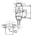
図2は、排水栓の駆動装置6の要部の具体的構成の一例を示す図であり、ケース13内の下部には、防水用のOリング21,22をそれぞれ介して、カバー23およびOリング押さえ24がそれぞれ装着されて水密構造とされている。カバー23の上部のステッピングモータ11は、下方に駆動軸としてのリードスクリュー25が延出しており、このリードスクリュー25には、ステッピングモータ11の内部で正逆方向に回転するインサートナット(図示せず)が螺合している。このリードスクリュー25には、左右に延びるストッパ26が一体に設けられており、このストッパ26の両端部が、カバー23の内壁のガイド溝に係合している。このリードスクリュー25は、ステッピングモータ11内部のインサートナットが正逆方向に回転することにより、前記ガイド溝に沿って回転することなく、昇降し、これによって、ワイヤ10を、上下方向に移動させるものである。すなわち、この図2では、ステッピングモータ11の駆動軸であるリードスクリュー25自体が、昇降する構成を示している。
【0033】
左右に延びるストッパ26の一方側には、上述のマグネット17が取り付けられる一方、カバー23の内部には、前記マグネット17を検出する近接スイッチ18が上下にそれぞれ実装された基板27が装備されており、リードスクリュー25の上限位置および下限位置をそれぞれ検出して位置規制できるように構成されている。
【0034】
ステッピングモータ11に隣接して、この参考例では、ステッピングモータ11の上方には、上述の制御基板12が設けられており、この制御基板12の下面のコネクタ28を介してステッピングモータ11と基板27が接続されている。この制御基板12の上面のLED15に対向する位置には、透明な導光部材29が設けられる一方、操作スイッチ14の上部は、排水栓7の開閉のために押圧操作される操作部31となっている。
【0035】
次に、この参考例の排水栓の駆動装置6による排水栓7の開閉動作を説明する。例えば、リードスクリュー25が下限位置にあって、駆動装置6側のワイヤ10を押し下げて排水栓7を上昇させて排水栓7が開いている状態で、操作部31が押圧操作されて操作スイッチ14が作動して制御基板12に制御信号が与えられる、あるいは、台所用リモコン5の排水栓スイッチ9が操作され、あるいは、給湯用リモコン4が操作されて、給湯器3のコントローラの制御モードが、湯張りモードになると、給湯器3から二芯伝送線Lを介して制御信号が直流電源に重畳されて制御基板12に与えられ、これによって、制御基板12は、ステッピングモータ11を駆動してリードスクリュー25を上限位置まで上昇させてワイヤ10の上昇を許容し、これによって、排水栓7の自重あるいは図示しないバネ等の付勢手段の付勢力によって排水栓7が降下して排水栓7が閉じるとともに、駆動装置6側のワイヤ10がリードスクリュー25に当接する位置まで上昇することになる。
【0036】
このリードスクリュー25が上限位置にあって排水栓7が閉じている状態において、操作部31が押圧操作されて操作スイッチ14が作動して制御基板12に制御信号が与えられる、あるいは、台所用リモコン5の排水栓スイッチ9が操作され、あるいは、給湯器3のコントローラの制御モードが排水モードになると、給湯器3から二芯伝送線Lを介して制御信号が直流電源に重畳されて制御基板12に与えられ、これによって、制御基板12は、ステッピングモータ11を駆動してリードスクリュー25を下降させ、これによって、駆動装置6側のワイヤ10が押し下げられて、排水栓7が上昇して開くことになる。
【0037】
この参考例の排水栓の駆動装置6では、ステッピングモータ11は、その駆動軸であるリードスクリュー25がワイヤ10の駆動装置6側の端部の軸線と同軸になるように配設され、その回転動力を、直線運動に変換してワイヤ10を駆動するので、図6の従来例のようにステッピングモータをケースの外方に配置する必要もなく、さらに、カムや支持筒などを設ける必要もなく、これによって、小型化を図ることができ、フランジ部が狭い浴槽にも設置できることになる。
【0038】
しかも、ステッピングモータ11の動作を制御する制御基板12を、ステッピングモータ11の上方に配置して操作スイッチ14とともに、ケース13に内装して一つのユニットとしているので、駆動部と制御部とが個別のユニットであった従来例に比べて、設置施工性やメンテナンス性が向上するとともに、コストの低減を図ることができる。特に、浴槽のフランジ部の下のスペースは、非常に狭いのであるが、1ユニット化によって設置施工が容易となる。
【0039】
また、図1に対応する図3に示されるように、制御基板12の下面にコネクタ40を設ける一方、ステッピングモータ11の上面に対応するコネクタ41を設けてワンタッチで制御基板12の取り付け、取り外しができるように構成してもよい。すなわち、排水栓の駆動装置6のケース13に、ステッピングモータ11等を組み込み、さらに、制御基板12をコネクタ40,41を介して接続し、その上面に操作部となるスイッチプレート42を取り付ける構成としてもよい。この構成によれば、組み立て時間が大幅に短縮される一方、制御基板12の接続を容易に外すことができるので、制御基板12の交換や修理が容易に行えることになる。
【0040】
さらに、上述の参考例では、排水栓の駆動装置6には、1本の二芯伝送線Lを介して制御信号と直流電源との両方が同時に供給されるので、排水栓の駆動装置6を施工する際の配線工事が簡略化される。
【0041】
なお、本発明の他の参考例として、図4に示されるように、給湯器以外の排水栓スイッチ43を有するとともに、電源回路およびコントローラを内蔵した別のユニット44に二芯伝送線Lを介して接続し、このユニット44から直流電源および制御信号を、排水栓の駆動装置6に供給する構成とすることもできる。
【0042】
また、本発明の実施の形態として、排水栓の駆動装置6を、浴槽のフランジ部などの組付け面に対して、上方から容易に着脱できる構成としてもよい。なお、その他の構成は、図1〜3の参考例または図4の他の参考例と同様である。
【0043】
すなわち、図5は、かかる組付けの構成を示す図であり、同図(c)は排水栓の駆動装置6のケース13を組付けた状態の側面図、同図(b)はその平面図、同図(a)は同図(c)の切断面線A−Aから見た図である。
【0044】
この実施の形態では、浴槽フランジ部35の取付け穴36に対して、内壁に周方向に沿って複数の係合凸部37aを有するカラー37を、上方から挿入する一方、ワッシャ38を介してナット39を、カラー37の外周のネジ部に螺合させて下方から締め付けて固定する。
【0045】
上面が押圧操作される操作部となっている排水栓の駆動装置6のケース13には、その外周に複数の係合凸部13aが形成されており、このケース13を、その係合凸部13aが、カラー37の係合凸部37aに当接しないようにして上方から挿入し、ケース13を円周方向に回転させてその係合凸部13aとカラー37の係合凸部37aとを係合させて組付ける。
【0046】
このケース13の組付けに際して、カラー37に対する位置合わせを容易に行えるように、カラー37の上面には、着脱位置にそれぞれ対応して位置合わせ用のマーク45が付される一方、ケース13の上面にも対応する位置合わせ用のマーク46が付されている。また、ケース13の上面には、上述の参考例で説明した排水栓の開閉にそれぞれ対応する位置に、上述のLED15の照光部47が設けられている。
【0047】
ケース13を、カラー37にガタツキなく組付けることができるように、係合面であるケース13の係合凸部13aの上面あるいはカラー37の係合凸部37aの下面を、テーパ状とするのが好ましい。また、テーパ状に形成するのではなく、樹脂材料の弾力性を利用してガタツキなく組付けるようにしてもよい。
【0048】
このようにフランジ部の上面から着脱できる構成とすることにより、上述のように駆動部と制御部とを1ユニットにしたことと相俟ってメンテナンス性が飛躍的に向上する。
【0049】
なお、本発明の他の実施の形態として、カラー37の内周にネジ部を設ける一方、ケース13の外周に前記ネジ部に螺合するネジ部を設け、ケース13をカラー37にネジ止め固定してもよい。
【0050】
【発明の効果】
以上のように請求項1の本発明によれば、駆動源を、その駆動軸が動力伝達部材の駆動源側の端部の軸線に沿うように配置しているので、動力伝達部材の軸線方向のスペースを有効に利用して当該排水栓装置を設けることができ、駆動源を前記軸線の外方に設ける従来例に比べて小型化を図ることができる。
また、駆動制御手段を構成する制御基板を、駆動源に隣接して配設するとともに、該制御基板に操作スイッチを接続したので、従来、個別のユニットであった駆動源と制御部(制御基板)とが、1ユニット化されることになり、設置施工性やメンテナンス性が向上するとともに、コストの低減を図ることができる。
さらに、駆動源、制御基板および操作スイッチが、ケースに内装されて水密構造とされて、前記ケースが、組付け面から着脱自在とされるので、設置施工性やメンテナンス性が一層向上する。
【0051】
請求項2の本発明によれば、ステッピングモータの回転動力が、ワイヤの軸線に沿う直線運動に変換されて該ワイヤに与えられるので、ステッピングモータの回転運動を、カムや支持筒などを介してワイヤの軸線方向の運動に変換する従来例に比べて構成が簡素化されて小型化を図ることができ、フランジ部が狭い浴槽などにも容易に設置できる。
【0054】
請求項3の本発明によれば、給湯器から電源が供給されるとともに、該電源に重畳されて制御信号が与えられるので、給湯器と当該排水栓の駆動装置との間の配線を、二芯伝送線などの1本で済ますことができ、設置施工時の配線作業が簡素化される。
【図面の簡単な説明】
【図1】 本発明の参考例に係る浴槽システムの構成図である。
【図2】 排水栓の駆動装置の要部の構成図である。
【図3】 図1の制御基板の接続を示す概略構成図である。
【図4】 本発明の他の参考例に係る浴槽システムの構成図である。
【図5】 本発明の実施の形態の組付け状態を示す図である。
【図6】 従来例の構成図である。
【符号の説明】
2 浴槽
3 給湯器
6 排水栓の駆動装置
7 排水栓
10 ワイヤ
11 ステッピングモータ
12 制御基板
13 ケース
14 操作スイッチ[0001]
BACKGROUND OF THE INVENTION
The present invention relates to a drain plug driving device that electrically opens and closes a drain plug attached to a bathtub.
[0002]
[Prior art]
As a conventional drain plug device that electrically opens and closes a drain plug attached to a bathtub, there is, for example, one described in Japanese Patent Laid-Open No. 10-212747 shown in FIG.
[0003]
In this drain plug device, when an electric operation switch (not shown) is opened and closed, this operation signal is input to a control unit (not shown), and the control unit drives the stepping
[0004]
[Problems to be solved by the invention]
In such a conventional example, a
[0005]
In addition, the control unit that controls the operation of the
[0006]
The present invention has been made in view of the above-mentioned points, and has as its main purpose to reduce the size of the drain plug drive device, and also to improve its installation workability and maintainability. And
[0007]
[Means for Solving the Problems]
The present invention is configured as follows in order to achieve the above-described object.
[0008]
That is, the drain plug driving device of the present invention according to
[0009]
According to a second aspect of the present invention, in the first aspect of the invention, the power transmission member is a wire, the drive source includes a stepping motor, and the rotational power of the stepping motor is in a linear motion along the axis. It is converted and given to the end of the wire on the drive source side.
[0012]
According to a third aspect of the present invention, in the first or second aspect of the present invention, the power source of the drain plug driving device is supplied from a hot water heater that is a hot water source of the bathtub, and is superimposed on the power source for the driving. The control signal for remote operation to the control means is given.
[0013]
According to the first aspect of the present invention, since the drive source is arranged so that the drive shaft is along the axis of the drive source side end of the power transmission member, the axial space of the power transmission member is reduced. The driving device for the drain plug can be provided effectively.
In addition, since the control board constituting the drive control means is disposed adjacent to the drive source, and the operation switch is connected to the control board, the drive unit and the control unit (control board), which have conventionally been separate units. ) Is made into one unit.
Furthermore, since the drive source, the control board, and the operation switch are built in the case to form a watertight structure, and the case is detachable from the assembly surface, installation workability and maintainability are improved.
[0014]
According to the second aspect of the present invention, since the rotational power of the stepping motor is converted into a linear motion along the axis of the wire and applied to the wire, the rotational motion of the stepping motor is transmitted via a cam or a support tube. Thus, the configuration is simplified and the size can be reduced as compared with the conventional example in which the movement is converted into the movement of the wire in the axial direction.
[0017]
According to the third aspect of the present invention, since power is supplied from the water heater and a control signal is given superimposed on the power supply, the wiring between the water heater and the drain plug driving device is One cable such as a two-core transmission line can be used.
[0018]
DETAILED DESCRIPTION OF THE INVENTION
Hereinafter, embodiments of the present invention will be described in detail with reference to the drawings.
[0019]
FIG. 1 is a configuration diagram of a bathtub system including a drain plug driving device according to a reference example of the present invention.
[0020]
In the figure, 1 is a bathroom, 2 is a bathtub, 3 is a water heater, 4 is a remote controller for hot water supply, 5 is a remote controller for kitchen, and 6 is a drive of a drain plug that opens and closes a
[0021]
The drain
[0022]
The
[0023]
Furthermore, the
[0024]
The
[0025]
The hot water supply remote controller 4 has at least a hot water supply start switch, a hot water supply stop switch, a temperature adjustment switch, and the like, and is installed on the inner surface of the side wall panel in the
[0026]
The kitchen
[0027]
The drain
[0028]
One end of the
[0029]
On the
[0030]
In the drain
[0031]
In FIG. 1, a schematic configuration of the drain
[0032]
FIG. 2 is a diagram showing an example of a specific configuration of a main part of the drain
[0033]
The above-described
[0034]
In this reference example , the
[0035]
Next, the opening / closing operation of the
[0036]
In a state where the
[0037]
In the drain
[0038]
In addition, since the
[0039]
Further, as shown in FIG. 3 corresponding to FIG. 1, while the
[0040]
Further, in the above-described reference example , both the control signal and the DC power supply are simultaneously supplied to the drain
[0041]
As another reference example of the present invention, as shown in FIG. 4, a
[0042]
Moreover, as an embodiment of the present invention, the drain
[0043]
That is, FIG. 5 is a view showing the structure of such assembly, wherein FIG. 5C is a side view of the state in which the
[0044]
In this embodiment, a
[0045]
The
[0046]
When the
[0047]
The upper surface of the engaging
[0048]
By adopting a structure that can be attached and detached from the upper surface of the flange portion in this way, the maintenance performance is greatly improved in combination with the drive portion and the control portion being integrated into one unit as described above.
[0049]
As another embodiment of the present invention, a screw portion is provided on the inner periphery of the
[0050]
【The invention's effect】
As described above, according to the first aspect of the present invention, the drive source is disposed so that the drive shaft thereof is along the axis of the drive source side end of the power transmission member. The drain plug device can be provided by effectively using the space, and the size can be reduced as compared with the conventional example in which the drive source is provided outside the axis.
In addition, since the control board constituting the drive control means is disposed adjacent to the drive source, and the operation switch is connected to the control board, the drive source and the control unit (control board), which are conventionally separate units, are provided. ) Is made into one unit, so that the installation workability and maintainability are improved, and the cost can be reduced.
Furthermore, since the drive source, the control board, and the operation switch are built in the case to form a watertight structure, and the case is detachable from the assembly surface, installation workability and maintainability are further improved.
[0051]
According to the present invention of
[0054]
According to the third aspect of the present invention, since power is supplied from the water heater and a control signal is given superimposed on the power supply, the wiring between the water heater and the drain valve driving device is connected to It can be done with a single core transmission line, etc., simplifying the wiring work during installation.
[Brief description of the drawings]
FIG. 1 is a configuration diagram of a bathtub system according to a reference example of the present invention .
FIG. 2 is a configuration diagram of a main part of a drain plug driving device.
FIG. 3 is a schematic configuration diagram showing connection of a control board in FIG. 1;
FIG. 4 is a configuration diagram of a bathtub system according to another reference example of the present invention.
FIG. 5 is a diagram showing an assembled state of the embodiment of the present invention.
FIG. 6 is a configuration diagram of a conventional example.
[Explanation of symbols]
DESCRIPTION OF
Claims (3)
前記駆動源は、その駆動軸が前記動力伝達部材の駆動源側の端部の軸線に沿うように配置され、
前記駆動制御手段を構成する制御基板を、前記駆動軸が下方に延出する駆動源に隣接して配設するとともに、該制御基板に、前記制御信号を出力する操作スイッチを接続し、
前記駆動源、前記制御基板および前記操作スイッチが、ケースに内装されて水密構造とされ、浴槽フランジ部または浴槽周辺部に組付けられるとともに、前記ケースが、組付け面から着脱自在とされることを特徴とする排水栓の駆動装置。A drive source that opens and closes the drain plug of the bathtub via a power transmission member, and a drive control means that controls the operation of the drive source, and the drain plug is controlled based on a control signal given to the drive control means. In the drain plug driving device that opens and closes,
The drive source is arranged such that its drive shaft is along the axis of the end of the power transmission member on the drive source side ,
A control board constituting the drive control means is disposed adjacent to a drive source in which the drive shaft extends downward, and an operation switch for outputting the control signal is connected to the control board,
The drive source, the control board, and the operation switch are built in a case to have a watertight structure, and are assembled to a bathtub flange portion or a bathtub peripheral portion, and the case is detachable from an assembly surface. A drain plug drive device characterized by the above.
Priority Applications (1)
| Application Number | Priority Date | Filing Date | Title |
|---|---|---|---|
| JP2000127098A JP4389345B2 (en) | 2000-04-27 | 2000-04-27 | Drain cock drive device |
Applications Claiming Priority (1)
| Application Number | Priority Date | Filing Date | Title |
|---|---|---|---|
| JP2000127098A JP4389345B2 (en) | 2000-04-27 | 2000-04-27 | Drain cock drive device |
Publications (2)
| Publication Number | Publication Date |
|---|---|
| JP2001311196A JP2001311196A (en) | 2001-11-09 |
| JP4389345B2 true JP4389345B2 (en) | 2009-12-24 |
Family
ID=18636755
Family Applications (1)
| Application Number | Title | Priority Date | Filing Date |
|---|---|---|---|
| JP2000127098A Expired - Fee Related JP4389345B2 (en) | 2000-04-27 | 2000-04-27 | Drain cock drive device |
Country Status (1)
| Country | Link |
|---|---|
| JP (1) | JP4389345B2 (en) |
Families Citing this family (9)
| Publication number | Priority date | Publication date | Assignee | Title |
|---|---|---|---|---|
| JP3882165B2 (en) * | 2002-02-25 | 2007-02-14 | 株式会社Inax | Drain plug device |
| JP3861201B2 (en) * | 2002-02-25 | 2006-12-20 | 株式会社Inax | Drain plug device |
| KR100711308B1 (en) | 2005-07-26 | 2007-04-25 | 윤창용 | Drain Apparatus for Bath |
| JP6539819B2 (en) * | 2014-12-01 | 2019-07-10 | 丸一株式会社 | Remote control drain device |
| CN104831787B (en) * | 2015-05-18 | 2016-04-27 | 慈溪市南盾电器有限公司 | Reservoir spinner |
| DE102017100535A1 (en) * | 2017-01-12 | 2018-07-12 | Blanco Gmbh + Co Kg | Actuation device for a valve of a drainage arrangement for a basin |
| JP7212932B2 (en) * | 2019-01-08 | 2023-01-26 | 株式会社日本アルファ | Electric operating device |
| JP2021017682A (en) * | 2019-07-17 | 2021-02-15 | 丸一株式会社 | Drain plug apparatus |
| KR102221050B1 (en) * | 2019-08-07 | 2021-02-26 | 손정우 | Faucet control system having drain function |
Family Cites Families (7)
| Publication number | Priority date | Publication date | Assignee | Title |
|---|---|---|---|---|
| JPS639978U (en) * | 1986-07-02 | 1988-01-22 | ||
| JPH03137454A (en) * | 1989-10-20 | 1991-06-12 | Matsushita Electric Ind Co Ltd | Automatic bath device |
| JPH07102196B2 (en) * | 1991-05-10 | 1995-11-08 | リンナイ株式会社 | Drainage method and device for bath equipment |
| JPH0710070U (en) * | 1993-07-19 | 1995-02-10 | エヌテーシー工業株式会社 | Electric drainage in bathtub |
| JPH07197502A (en) * | 1993-12-30 | 1995-08-01 | Inax Corp | Drain cock for bathtub |
| JP2000110219A (en) * | 1998-10-09 | 2000-04-18 | Toto Ltd | Drainage device |
| JP4337194B2 (en) * | 1999-11-30 | 2009-09-30 | 株式会社ノーリツ | Bathtub drain valve and bathtub |
-
2000
- 2000-04-27 JP JP2000127098A patent/JP4389345B2/en not_active Expired - Fee Related
Also Published As
| Publication number | Publication date |
|---|---|
| JP2001311196A (en) | 2001-11-09 |
Similar Documents
| Publication | Publication Date | Title |
|---|---|---|
| JP4389345B2 (en) | Drain cock drive device | |
| JP4745889B2 (en) | Automatic faucet device | |
| JP2000073426A (en) | Drainage device | |
| JP7212931B2 (en) | electric operating device | |
| JP4858830B2 (en) | Remote control switch for drain valve | |
| KR100750579B1 (en) | Toilet bowl washing system | |
| JPH10212747A (en) | Drain tap device | |
| JP2003113635A (en) | Drain plug device | |
| JP3861201B2 (en) | Drain plug device | |
| KR101949487B1 (en) | Valve assembly | |
| US9882451B2 (en) | Automatic flush sensing assembly | |
| JP5040085B2 (en) | Bathtub operation device | |
| CN218970149U (en) | Electric control device of drainer | |
| JP4568993B2 (en) | Operation device for bathroom | |
| KR20220007285A (en) | Automatic and manual flushing device for toilet bowl | |
| JP2003049467A (en) | Bathtub device | |
| KR100964331B1 (en) | Water supply valve and automatic tap using the same | |
| JP2003049465A (en) | Drain plug device | |
| JP2003049468A (en) | Drain plug device | |
| JP2003247254A (en) | Drain valve device | |
| JP4422060B2 (en) | Flush valve device | |
| JP7286130B2 (en) | Operating device | |
| JP2002061250A (en) | Automatic drain cock device having manual open-close function | |
| CN211449818U (en) | Switch type electric actuator | |
| JP2003049464A (en) | Drain plug device |
Legal Events
| Date | Code | Title | Description |
|---|---|---|---|
| A621 | Written request for application examination |
Free format text: JAPANESE INTERMEDIATE CODE: A621 Effective date: 20070423 |
|
| A977 | Report on retrieval |
Free format text: JAPANESE INTERMEDIATE CODE: A971007 Effective date: 20090528 |
|
| A131 | Notification of reasons for refusal |
Free format text: JAPANESE INTERMEDIATE CODE: A131 Effective date: 20090602 |
|
| A521 | Written amendment |
Free format text: JAPANESE INTERMEDIATE CODE: A523 Effective date: 20090710 |
|
| TRDD | Decision of grant or rejection written | ||
| A01 | Written decision to grant a patent or to grant a registration (utility model) |
Free format text: JAPANESE INTERMEDIATE CODE: A01 Effective date: 20090915 |
|
| A01 | Written decision to grant a patent or to grant a registration (utility model) |
Free format text: JAPANESE INTERMEDIATE CODE: A01 |
|
| A61 | First payment of annual fees (during grant procedure) |
Free format text: JAPANESE INTERMEDIATE CODE: A61 Effective date: 20090928 |
|
| FPAY | Renewal fee payment (event date is renewal date of database) |
Free format text: PAYMENT UNTIL: 20121016 Year of fee payment: 3 |
|
| R150 | Certificate of patent or registration of utility model |
Free format text: JAPANESE INTERMEDIATE CODE: R150 |
|
| FPAY | Renewal fee payment (event date is renewal date of database) |
Free format text: PAYMENT UNTIL: 20131016 Year of fee payment: 4 |
|
| R250 | Receipt of annual fees |
Free format text: JAPANESE INTERMEDIATE CODE: R250 |
|
| R250 | Receipt of annual fees |
Free format text: JAPANESE INTERMEDIATE CODE: R250 |
|
| LAPS | Cancellation because of no payment of annual fees |