JP4387721B2 - Recording apparatus and recording method - Google Patents
Recording apparatus and recording method Download PDFInfo
- Publication number
- JP4387721B2 JP4387721B2 JP2003284384A JP2003284384A JP4387721B2 JP 4387721 B2 JP4387721 B2 JP 4387721B2 JP 2003284384 A JP2003284384 A JP 2003284384A JP 2003284384 A JP2003284384 A JP 2003284384A JP 4387721 B2 JP4387721 B2 JP 4387721B2
- Authority
- JP
- Japan
- Prior art keywords
- recording
- ink
- dots
- black ink
- color
- Prior art date
- Legal status (The legal status is an assumption and is not a legal conclusion. Google has not performed a legal analysis and makes no representation as to the accuracy of the status listed.)
- Expired - Fee Related
Links
- 238000000034 method Methods 0.000 title claims description 35
- 239000000976 ink Substances 0.000 claims description 231
- 238000001454 recorded image Methods 0.000 claims description 25
- 230000003247 decreasing effect Effects 0.000 claims 2
- 239000007787 solid Substances 0.000 description 16
- 230000006870 function Effects 0.000 description 9
- 238000010586 diagram Methods 0.000 description 7
- 238000011084 recovery Methods 0.000 description 7
- 230000015556 catabolic process Effects 0.000 description 4
- 238000006731 degradation reaction Methods 0.000 description 4
- 239000003086 colorant Substances 0.000 description 2
- 238000007599 discharging Methods 0.000 description 2
- 230000015572 biosynthetic process Effects 0.000 description 1
- 238000009835 boiling Methods 0.000 description 1
- 238000006243 chemical reaction Methods 0.000 description 1
- 230000006866 deterioration Effects 0.000 description 1
- 238000009792 diffusion process Methods 0.000 description 1
- 238000005187 foaming Methods 0.000 description 1
- 230000001771 impaired effect Effects 0.000 description 1
- 239000007788 liquid Substances 0.000 description 1
- 239000002184 metal Substances 0.000 description 1
- 238000003672 processing method Methods 0.000 description 1
- 238000013139 quantization Methods 0.000 description 1
Images


Classifications
-
- H—ELECTRICITY
- H04—ELECTRIC COMMUNICATION TECHNIQUE
- H04N—PICTORIAL COMMUNICATION, e.g. TELEVISION
- H04N1/00—Scanning, transmission or reproduction of documents or the like, e.g. facsimile transmission; Details thereof
- H04N1/40—Picture signal circuits
- H04N1/405—Halftoning, i.e. converting the picture signal of a continuous-tone original into a corresponding signal showing only two levels
-
- B—PERFORMING OPERATIONS; TRANSPORTING
- B41—PRINTING; LINING MACHINES; TYPEWRITERS; STAMPS
- B41J—TYPEWRITERS; SELECTIVE PRINTING MECHANISMS, i.e. MECHANISMS PRINTING OTHERWISE THAN FROM A FORME; CORRECTION OF TYPOGRAPHICAL ERRORS
- B41J2/00—Typewriters or selective printing mechanisms characterised by the printing or marking process for which they are designed
- B41J2/005—Typewriters or selective printing mechanisms characterised by the printing or marking process for which they are designed characterised by bringing liquid or particles selectively into contact with a printing material
- B41J2/01—Ink jet
- B41J2/21—Ink jet for multi-colour printing
- B41J2/2132—Print quality control characterised by dot disposition, e.g. for reducing white stripes or banding
Description
本発明は、インクのドットを形成することによって画像を記録する記録装置および記録方法に関し、より詳細には、記録データに基づいてインクを付与することによって、被記録媒体上にインクのドットを形成して文字や画像を記録する記録装置および記録方法に関するものである。 The present invention relates to a recording apparatus and a recording method for recording an image by forming ink dots, and more specifically, ink dots are formed on a recording medium by applying ink based on recording data. The present invention relates to a recording apparatus and a recording method for recording characters and images.
プリンタ、複写機、ファクシミリ等の記録装置としては、紙やプラスチック薄板等の被記録媒体上に、画像情報に基づいてドットパターンを形成することによって画像を記録する記録装置を挙げることができる。このような記録装置には、インクジェット式、ワイヤドット式、サーマル式、レーザービーム式等、様々な記録方式があり、近年、記録の高速化、画像の高品質化(高解像度化)、低騒音化などが要求されている。これらの要求に応える記録装置としては、インクジェット式の記録装置(インクジェット記録装置)がある。このインクジェット式の記録装置は、記録ヘッドの吐出口から吐出したインク(記録液)滴を被記録媒体に付着させることにより画像を記録する。また、被記録媒体と非接触で記録を行うことが可能であるため、種々の被記録媒体に対して安定した画像を記録することができる。また、記録ヘッドから吐出するインクの多色化も容易であるため、ブラックインクによるテキスト(文字)から多色インクによるカラー画像まで様々なデータの記録に利用されている。この場合、ブラックインクによるテキストの記録には記録速度が重視され、多色インクによるカラー画像の記録には画像の粒状性や階調性が重視される。そのため、インクジェット記録装置として、ブラックインクの吐出量は比較的大きくし、それを2値データ(インクの吐出、不吐出に対応するデータ)に基づいて吐出することによってテキストを記録し、一方、ブラック以外のシアン、マゼンタ、イエローなどの多色インク(以下、「カラーインク」ともいう)の吐出量は比較的小さくし、それらを多値データに基づいて吐出することによってカラー画像を記録するものが存在する。 Examples of the recording apparatus such as a printer, a copying machine, and a facsimile include a recording apparatus that records an image by forming a dot pattern on a recording medium such as paper or a plastic thin plate based on image information. There are various recording systems such as ink jet, wire dot, thermal, and laser beam systems. Recently, recording speed has been increased, image quality has been improved (resolution increased), and noise has been reduced. Is required. As a recording apparatus that meets these requirements, there is an ink jet recording apparatus (ink jet recording apparatus). This ink jet recording apparatus records an image by adhering ink (recording liquid) droplets ejected from ejection ports of a recording head to a recording medium. In addition, since recording can be performed without contact with the recording medium, stable images can be recorded on various recording media. In addition, since it is easy to increase the number of colors of ink ejected from the recording head, it is used for recording various data from text (characters) using black ink to color images using multicolor ink. In this case, the recording speed is important for text recording with black ink, and the granularity and gradation of the image are important for recording a color image with multicolor ink. Therefore, as an inkjet recording apparatus, the amount of black ink discharged is relatively large, and text is recorded by discharging it based on binary data (data corresponding to ink discharge and non-discharge). Other than the above, the discharge amount of multi-color ink such as cyan, magenta and yellow (hereinafter also referred to as “color ink”) is relatively small, and a color image is recorded by discharging them based on multi-value data. Exists.
このようなインクジェット記録装置においては、従来から、インク消費量の低減や記録速度の向上を目的として、通常よりも記録濃度を低くして記録する方法が提案されている。 In such an ink jet recording apparatus, conventionally, a method of recording at a recording density lower than usual has been proposed for the purpose of reducing the ink consumption and improving the recording speed.
例えば、特許文献1には、記録解像度が600dpi(ドット/インチ)の2×2のマス目(記録領域)に記録ドットが存在する場合に、記録解像度が300dpiの1×1のマス目に1ドットを記録するように、記録解像度を低解像度に変換する画像処理方法が提案されている。また、特許文献2には、記録信号の1画素分を複数のビットマップに展開し、1画素当たり少なくとも1ドットを含むように間引いて画像を記録する方法が提案されている。
For example,
その他、通常の記録データが600dpiの比較的高解像で処理されている場合に、それを比較的低解像度の300dpiで処理することによって処理時間を低減させたり、または300dpiの2値のデータをビットマップを用いて600dpiに解像度変換する場合に、600dpiの2×2の4つのマス目の内、2ドットしか記録しないことによりインク消費量を減らしたり、記録速度を向上させる制御が知られている。
In addition, when normal recording data is processed at a relatively high resolution of 600 dpi, the processing time is reduced by processing it at a relatively low resolution of 300 dpi, or binary data of 300 dpi is reduced. In the case of resolution conversion to 600 dpi using a bitmap, it is known to control to reduce ink consumption or improve recording speed by recording only 2 dots out of 4
しかしながら、記録データを間引いての間引き記録を行う場合には、ブラックインクによって記録するテキスト(文字)の記録品位と、カラーインクによるカラー画像の記録品位とを両立させることは困難であった。 However, when thinning recording is performed by thinning recording data, it is difficult to achieve both the recording quality of text (characters) recorded with black ink and the recording quality of a color image with color ink.
すなわち、特許文献1の場合には、その文献中に記載されているように、1ドット幅の細線を欠落させずに記録できるものの、画像の記録に関しては、記録解像度が600dpiの2×2のマス目に1ドットが以上存在する場合に、記録濃度が同一になって、階調性が失われてしまう欠点がある。例えば、図15(a)のように、600dpiの記録解像度において記録デューティー(Duty)が50%均一のベタ画像(50%Dutyベタ画像)を考える。この画像を通常の600dpiの2値データに対応させて記録した場合、つまり600dpiの1×1のマス目内にインクを吐出するか否かの2値(「1」または「0」)のデータに対応させて記録した場合には、図15(b)のような50%デューティーの画像として記録されることになる。つまり、600dpiの2×2のマス目内に2ドットが形成されることになる。この画像に関して特許文献1の画像処理を施した場合には、図15(c)のように、300dpiの1×1のマス目内に1ドットが形成されて、記録デューティーが100%のベタ画像となる。次に、図16(a)のように、600dpiの記録密度において記録デューティー(Duty)が25%均一のベタ画像(25%Dutyベタ画像)を考える。この画像を通常の600dpiの2値データに対応させて記録した場合には、図16(b)のような記録デューティー25%の画像として記録されることになる。図15の場合と同様に、この画像に関して特許文献1の画像処理を施した場合には、図16(c)のように、300dpiの1×1のマス目内に1ドットが形成されて記録デューティー100%のベタ画像となってしまい、図15(c)の画像と区別できない。そのため、特許文献1の画像処理によっては、画像の階調性が著しく損なわれるおそれがある。
That is, in the case of
一方、特許文献2の場合には、1画素を複数のドットで記録することが前提となっており、1画素に対して最大1ドットを記録するような場合には実施することができない。また、1画素を複数のドットで記録する場合には、特許文献2にも記載されているように記録速度が遅くなってしまう。さらに、1画素をN(2以上の整数)ドットで記録する場合には、1/Nの間引きしか行えないため、十分な記録品位が得られない場合がある。
On the other hand, in the case of
また、ドットを間引いて記録する間引き記録時に、記録解像度を下げた場合には次のような問題が生じる。 In addition, the following problems occur when the recording resolution is lowered during thinning recording in which dots are thinned out.
例えば、図17(a)のように、600dpiの記録解像度において記録デューティー(Duty)が25%均一のベタ画像(25%Dutyベタ画像)を考える。この画像を通常の600dpiの2値データに対応させて記録した場合には、図17(b)のような記録デューティー25%の画像として記録されることになる。また、図17(a)の画像を300dpiの2値データに対応させて記録した場合には、図17(c)のようなドット配置となる。この図17(c)の300dpiの画像を600dpiの高解像度に展開した場合、つまり300dpiの1×1のマス目における2値データを600dpiの2×2のマス目内に展開する場合に、仮に、ドットを50%間引いて記録すると図17(d)の画像となる。すなわち、通常は2×2のマス目に4ドット形成するドットを50%間引いて、2ドットのみ形成することによって、図17(d)の画像が記録されることになる。図17(d)の画像は、図17(b)と比較して記録ドット数が50%間引かれるため、インク消費量を減らしたり、記録速度を向上させることはできる。しかし、2ドットが対をなすように記録されるため、ドット配置の均一性が失われてしまう。このように、間引き記録を行うために記録解像度を下げてから、1画素を形成するドット数を減らした場合には、画像の記録品位が低下してしまう。 For example, as shown in FIG. 17A, consider a solid image (25% duty solid image) with a recording duty (Duty) of 25% uniform at a recording resolution of 600 dpi. When this image is recorded in correspondence with normal 600 dpi binary data, it is recorded as an image with a recording duty of 25% as shown in FIG. In addition, when the image of FIG. 17A is recorded in correspondence with 300 dpi binary data, the dot arrangement is as shown in FIG. When the 300 dpi image of FIG. 17C is expanded to a high resolution of 600 dpi, that is, when binary data in a 300 × 1 1 × 1 cell is expanded into a 2 × 2 cell of 600 dpi, When dots are thinned out by 50% and recorded, an image shown in FIG. That is, the image shown in FIG. 17D is recorded by forming only 2 dots by thinning out 50% of dots that are normally formed in 2 × 2 squares. In the image of FIG. 17D, the number of recording dots is thinned out by 50% compared to FIG. 17B, so that the ink consumption can be reduced and the recording speed can be improved. However, since the two dots are recorded in pairs, the uniformity of the dot arrangement is lost. As described above, when the number of dots forming one pixel is reduced after the recording resolution is lowered in order to perform thinning recording, the recording quality of the image is deteriorated.
このように、従来の記録装置では、記録に用いるインク量を減らした間引き記録を行う場合に、画像品位の劣化が生じてしまう場合があった。また画像劣化を発生させないためには、通常の記録時に1画素を複数のドットで記録し、間引き記録時に1画素当たりのドット数を減らして記録する必要があり、その場合には、通常の記録速度が遅くなってしまう。 As described above, in the conventional recording apparatus, there is a case where the image quality is deteriorated when thinning recording is performed with the amount of ink used for recording being reduced. In order to prevent image degradation, it is necessary to record one pixel with a plurality of dots during normal recording and reduce the number of dots per pixel during thinning recording. In this case, normal recording is required. The speed will be slow.
本発明の目的は、記録品位を確保するように、ドットを適確に間引いて記録することができる記録装置および記録方法を提供することにある。 An object of the present invention is to provide a recording apparatus and a recording method capable of recording by appropriately thinning out dots so as to ensure recording quality.
本発明の記録装置は、多値の記録データより生成される2値の記録データに基づいて被記録媒体にブラックインクおよびカラーインクのドットを形成することによって画像を記録可能な記録装置において、最終的な記録画像のブラックインクの濃度を低くするときに、前記ブラックインクに対応する多値の記録データが記録画像のブラックインクの濃度と比例関係となるように前記ブラックインクに対応する多値の記録データを補正する処理において、前記ブラックインクに対応する多値の記録データを変更してブラックインクのドット数を少なくするブラック記録制御手段と、最終的な記録画像のカラーインクの濃度を低くするときに、1記録画素に形成するカラーインクのドットの数を定めた前記カラーインクに対応する多値の記録データを変更してカラーインクのドット数を少なくするカラー記録制御手段と、を備えることを特徴とする。 The recording apparatus of the present invention is a recording apparatus capable of recording an image by forming dots of black ink and color ink on a recording medium based on binary recording data generated from multi- value recording data. When the density of the black ink in a typical recorded image is lowered, the multivalued recording data corresponding to the black ink is proportional to the density of the black ink in the recorded image. In the process of correcting the recording data, the black recording control means for reducing the number of dots of the black ink by changing the multi-value recording data corresponding to the black ink, and reducing the density of the color ink of the final recording image Sometimes, multi-valued recording data corresponding to the color ink in which the number of dots of the color ink to be formed in one recording pixel is determined. And color recording control means for reducing the number of dots of color ink by changing the data.
本発明の記録装置は、多値の記録データより生成される2値の記録データに基づいて被記録媒体にブラックインクおよびカラーインクのドットを形成することによって画像を記録可能な記録装置において、最終的な記録画像のブラックインクの濃度を低くするときに、前記ブラックインクに対応する多値の記録データが記録画像のブラックインクの濃度と比例関係となるように前記ブラックインクに対応する多値の記録データを補正する処理において、前記ブラックインクに対応する多値の記録データを変更してブラックインクのドット数を少なくするブラック記録制御手段と、最終的な記録画像のカラーインクの濃度を低くするときに、1記録画素に形成するカラーインクのドットの数を定めた前記カラーインクに対応する多値の記録データをドットパターンに基づいて前記カラーインクに対応する2値の記録データに変換する際にカラーインクのドット数を少なくするカラー記録制御手段と、を備えることを特徴とする。 The recording apparatus of the present invention is a recording apparatus capable of recording an image by forming dots of black ink and color ink on a recording medium based on binary recording data generated from multi-value recording data. When the density of the black ink in a typical recorded image is lowered, the multivalued recording data corresponding to the black ink is proportional to the density of the black ink in the recorded image. In the process of correcting the recording data, the black recording control means for changing the multi-value recording data corresponding to the black ink to reduce the number of dots of the black ink and the density of the color ink of the final recording image are reduced. Sometimes, multi-valued recording data corresponding to the color ink in which the number of dots of the color ink formed on one recording pixel is determined. The characterized in that it comprises a color recording control means for reducing the number of dots color ink when converting into binary recording data corresponding to the color inks on the basis of the dot pattern.
本発明の記録方法は、多値の記録データより生成される2値の記録データに基づいて被記録媒体にブラックインクおよびカラーインクのドットを形成することによって画像を記録可能な記録方法において、最終的な記録画像のブラックインクの濃度を低くするときに、前記ブラックインクに対応する多値の記録データが記録画像のブラックインクの濃度と比例関係となるように前記ブラックインクに対応する多値の記録データを補正する処理において、前記ブラックインクに対応する多値の記録データを変更してブラックインクのドット数を少なくし、最終的な記録画像のカラーインクの濃度を低くするときに、1記録画素に形成するカラーインクのドットの数を定めた前記カラーインクに対応する多値の記録データを変更してカラーインクのドット数を少なくすることを特徴とする。 The recording method of the present invention is a recording method capable of recording an image by forming dots of black ink and color ink on a recording medium based on binary recording data generated from multi- value recording data. When the density of the black ink in a typical recorded image is lowered, the multivalued recording data corresponding to the black ink has a proportional relationship with the density of the black ink in the recorded image. in the process of correcting the recording data, when a reduced number of dots black ink by changing the multi-valued print data corresponding to the black ink, the density of the color inks in the final recorded image low, 1 records Color ink by changing multi-valued recording data corresponding to the color ink in which the number of dots of color ink to be formed on a pixel is determined Characterized in that to reduce the number of dots.
本発明の記録方法は、多値の記録データより生成される2値の記録データに基づいて被記録媒体にブラックインクおよびカラーインクのドットを形成することによって画像を記録可能な記録方法において、最終的な記録画像のブラックインクの濃度を低くするときに、前記ブラックインクに対応する多値の記録データが記録画像のブラックインクの濃度と比例関係となるように前記ブラックインクに対応する多値の記録データを補正する処理において、前記ブラックインクに対応する多値の記録データを変更してブラックインクのドット数を少なくし、最終的な記録画像のカラーインクの濃度を低くするときに、1記録画素に形成するカラーインクのドットの数を定めた前記カラーインクに対応する多値の記録データをドットパターンに基づいて前記カラーインクに対応する2値の記録データに変換する際にカラーインクのドット数を少なくすることを特徴とする。 The recording method of the present invention is a recording method capable of recording an image by forming dots of black ink and color ink on a recording medium based on binary recording data generated from multi-value recording data. When the density of the black ink in a typical recorded image is lowered, the multivalued recording data corresponding to the black ink is proportional to the density of the black ink in the recorded image. In the process of correcting the recording data, when the multi-value recording data corresponding to the black ink is changed to reduce the number of dots of the black ink and the density of the color ink of the final recording image is lowered, one recording is performed. Based on the dot pattern, multivalued recording data corresponding to the color ink in which the number of dots of the color ink to be formed on the pixel is determined Characterized by reducing the number of dots color ink when converting into binary recording data corresponding to the color inks Te.
本発明によれば、インクの種類および1記録画素に対するドットの形成数に応じて、ドットを適確に間引いて記録することにより、記録品位を確保することができる。具体的には、ブラックインクによるテキスト(文字)などの記録画像とカラーインクによるカラーの記録画像のそれぞれに適応した間引き方式を採用したり、あるいは1記録画素に対して形成するドット数が1ドットか複数ドットかに応じた間引き方式を採用することにより、画質の劣化を最小限に抑えた間引き記録を実現することができる。 According to the present invention, it is possible to ensure recording quality by appropriately thinning and recording dots according to the type of ink and the number of dots formed for one recording pixel. Specifically, a thinning method adapted to each of a recording image such as text (character) using black ink and a color recording image using color ink is employed, or the number of dots formed for one recording pixel is 1 dot. By adopting a thinning method according to whether it is a plurality of dots, it is possible to realize thinning recording with minimal degradation of image quality.
以下、本発明の実施形態を図面に基づいて説明する。以下の実施形態は、インクジェット記録装置に対する適用例である。 Hereinafter, embodiments of the present invention will be described with reference to the drawings. The following embodiment is an example applied to an inkjet recording apparatus.
まず、本発明の実施形態の説明に先立ち、本発明を適用可能なインクジェット記録装置の基本構成の一例を図1から図2に基づいて説明する。
(インクジェット記録装置の基本構成例)
図1および図2は、本発明を適用可能なインクジェット記録装置の要部の概略構成図である。
First, prior to the description of embodiments of the present invention, an example of a basic configuration of an ink jet recording apparatus to which the present invention can be applied will be described with reference to FIGS.
(Example of basic configuration of inkjet recording apparatus)
1 and 2 are schematic configuration diagrams of the main part of an ink jet recording apparatus to which the present invention is applicable.
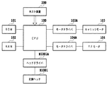
図1において、記録装置の外装部材内に収納されたシャーシM3019は、所定の剛性を有する複数の板状金属部材によって構成されて、記録装置の骨格を成すものであり、次のような各記録動作機構を保持する。自動給送部M3022は、用紙(被記録媒体)を装置本体内へと自動的に給送する。搬送部M3029は、自動給送部M3022から1枚ずつ送出される用紙を所定の記録位置へと導くと共に、その記録位置から排出部M3030へと用紙を導く。矢印Yは、用紙の搬送方向(副走査方向)である。記録位置に搬送された用紙は、記録部によって所望の記録が行われる。この記録部に対しては、回復部M5000によって回復処理が行われる。M2015は紙間調整レバー、M3006は、LFローラM3001の軸受けである。 In FIG. 1, a chassis M3019 housed in the exterior member of the recording apparatus is composed of a plurality of plate-shaped metal members having a predetermined rigidity and constitutes the skeleton of the recording apparatus. Holds the operating mechanism. The automatic feeding unit M3022 automatically feeds paper (recording medium) into the apparatus main body. The conveyance unit M3029 guides the sheets sent one by one from the automatic feeding unit M3022 to a predetermined recording position, and guides the sheet from the recording position to the discharge unit M3030. An arrow Y is the paper transport direction (sub-scanning direction). A desired recording is performed on the sheet conveyed to the recording position by the recording unit. Recovery processing is performed on the recording unit by the recovery unit M5000. M2015 is a paper gap adjusting lever, and M3006 is a bearing of the LF roller M3001.
記録部において、キャリッジM4001は、キャリッジ軸M4021によって矢印Xの主走査方向に移動可能に支持されている。このキャリッジM4001には、インクを吐出可能なインクジェット記録ヘッドH1001(図2参照)が着脱可能に搭載される。本例の記録ヘッドH1001は、図2のように、インクを貯留するインクタンクH1900と共に、記録ヘッドカートリッジH1000を構成する。インクタンクH1900としては、写真調の高画質なカラー記録を可能とするために、例えば、ブラック、ライトシアン、ライトマゼンタ、シアン、マゼンタおよびイエローの各色独立のインクタンクが用意されている。これらのインクタンクH1900のそれぞれは、記録ヘッドH1001に対して着脱自在となっている。 In the recording unit, the carriage M4001 is supported by the carriage shaft M4021 so as to be movable in the main scanning direction indicated by the arrow X. An ink jet recording head H1001 (see FIG. 2) capable of ejecting ink is detachably mounted on the carriage M4001. As shown in FIG. 2, the recording head H1001 of this example constitutes a recording head cartridge H1000 together with an ink tank H1900 that stores ink. As the ink tank H1900, for example, black, light cyan, light magenta, cyan, magenta, and yellow independent ink tanks are prepared in order to enable photographic-tone high-quality color recording. Each of these ink tanks H1900 is detachable from the recording head H1001.
記録ヘッドH1001は、インクを吐出するためのエネルギーとして、電気熱変換体から発生する熱エネルギーを利用するものであってもよい。その場合には、電気熱変換体の発熱によってインクに膜沸騰を生じさせ、そのときの発泡エネルギーによって、インク吐出口からインクを吐出することができる。 The recording head H1001 may use thermal energy generated from the electrothermal converter as energy for ejecting ink. In that case, film boiling occurs in the ink due to the heat generated by the electrothermal transducer, and the ink can be ejected from the ink ejection port by the foaming energy at that time.
回復部M5000には、記録ヘッドH1001におけるインク吐出口の形成面をキャップするキャップ(図示せず)が備えられている。このキャップには、その内部に負圧を導入可能な吸引ポンプを接続してもよい。その場合には、記録ヘッドH1001のインク吐出口を覆ったキャップ内に負圧を導入して、インク吐出口からインクを吸引排出させることにより、記録ヘッドH1001の良好なインク吐出状態を維持すべく回復処理(「吸引回復処理」ともいう)をすることができる。また、キャップ内に向かって、インク吐出口から画像の記録に寄与しないインクを吐出させることによって、記録ヘッドH1001の良好なインク吐出状態を維持すべく回復処理(「吐出回復処理」ともいう)をすることができる。 The recovery unit M5000 is provided with a cap (not shown) that caps the ink discharge port formation surface of the recording head H1001. A suction pump capable of introducing a negative pressure into the cap may be connected to the cap. In that case, a negative pressure is introduced into the cap covering the ink discharge port of the recording head H1001, and the ink is sucked and discharged from the ink discharge port to maintain a good ink discharge state of the recording head H1001. Recovery processing (also referred to as “suction recovery processing”) can be performed. Further, a recovery process (also referred to as “ejection recovery process”) is performed to maintain a good ink ejection state of the recording head H1001 by ejecting ink that does not contribute to image recording from the ink ejection port toward the inside of the cap. can do.
また、キャリッジM4001には、図1のように、キャリッジM4001上の所定の装着位置に記録ヘッドH1001を案内するためのキャリッジカバーM4002が設けられている。さらに、キャリッジM4001には、記録ヘッドH1001のタンクホルダーと係合して、記録ヘッドH1001を所定の装着位置にセットさせるヘッドセットレバーM4007が設けられている。ヘッドセットレバーM4007は、キャリッジM4001の上部に位置するヘッドセットレバー軸に対して回動可能に設けられており、記録ヘッドH1001と係合する係合部には、ばね付勢されるヘッドセットプレート(不図示)が備えられている。そのばね力によって、ヘッドセットレバーM4007は、記録ヘッドH1001を押圧しながらキャリッジM4001に装着する。 As shown in FIG. 1, the carriage M4001 is provided with a carriage cover M4002 for guiding the recording head H1001 to a predetermined mounting position on the carriage M4001. Further, the carriage M4001 is provided with a head set lever M4007 that engages with the tank holder of the recording head H1001 to set the recording head H1001 at a predetermined mounting position. The head set lever M4007 is provided so as to be rotatable with respect to a head set lever shaft positioned at the upper part of the carriage M4001. (Not shown) is provided. With the spring force, the head set lever M4007 is mounted on the carriage M4001 while pressing the recording head H1001.
図3は、このような記録装置における制御系の概略のブロック構成図である。 FIG. 3 is a schematic block diagram of a control system in such a recording apparatus.
図3において、CPU100は、本例のプリント装置の動作の制御処理やデータ処理等を実行する。ROM101は、それらの処理手順等のプログラムが格納され、またRAM102は、それらの処理を実行するためのワークエリアなどとして用いられる。記録ヘッドH1001からのインクの吐出は、CPU100が電気熱変換体などの駆動データ(記録データ)および駆動制御信号(ヒートパルス信号)をヘッドドライバH1001Aに供給することにより行われる。CPU100は、キャリッジM001を主走査方向に駆動するためのキャリッジモータ203をモータドライバ203Aを介して制御し、また用紙を副走査方向に搬送するためのP.Fモータ104をモータドライバ104Aを介して制御する。
In FIG. 3, the
以上のような構成のインクジェット記録装置によって記録を行う場合には、まず、ホスト装置200(図3参照)から外部I/Fを通して送出されてきた記録データをプリントバッファに一旦格納する。そして、キャリッジモータ103によってキャリッジM4001と共に記録ヘッドH1001を主走査方向させつつ、記録データに基づいて記録ヘッドH1001からインクを吐出させる記録動作と、P.Fモータ104によって用紙を副走査方向に所定量搬送する搬送動作と、を繰り返すことによって、用紙上に順次画像を記録する。
When recording is performed by the ink jet recording apparatus having the above configuration, first, recording data sent from the host apparatus 200 (see FIG. 3) through the external I / F is temporarily stored in the print buffer. A recording operation in which ink is ejected from the recording head H1001 based on recording data while the recording head H1001 is moved in the main scanning direction together with the carriage M4001 by the
(第1の実施形態)
図4から図9は、上述したインクジェット記録装置にも適応可能な本発明の第1の実施形態を説明するための図である。
(First embodiment)
FIGS. 4 to 9 are diagrams for explaining the first embodiment of the present invention that can be applied to the above-described inkjet recording apparatus.
図4および図5は、通常記録の際に形成されるドットの説明図である。本実施形態では、ブラックインクに関しては、そのインクを用いたテキスト(文字)などの画像の記録速度を重視する観点から、図4(a)のようにドット径を大きくすべく吐出量を30plとする。記録デューティーが100%均一のときは、図5(a)のように記録解像度600dpiの基本格子内(1×1の領域内)に1ドットを形成して、ブラックインクのベタ画像を記録する。一方、ブラック以外の色のインク(以下、「カラーインク」ともいう)に関しては、それらのインクを用いた記録画像の階調性や粒状性を重視する観点から、図4(b)のようにドット径を小さくすべく吐出量を5plとする。記録デューティーが100%均一のときは、図5(b)のように記録解像度600dpiの基本格子内に2ドットを重ねて形成して、カラーインクのベタ画像を記録する。図4(b)において、カラーインクの2つのドットは基本格子内においてずらされているが、それらのドットは基本格子内において重ねて形成されればよい。 4 and 5 are explanatory diagrams of dots formed during normal recording. In the present embodiment, with respect to the black ink, from the viewpoint of emphasizing the recording speed of an image such as text (character) using the ink, the discharge amount is set to 30 pl to increase the dot diameter as shown in FIG. To do. When the recording duty is 100% uniform, as shown in FIG. 5A, one dot is formed in a basic grid (in a 1 × 1 area) with a recording resolution of 600 dpi, and a solid image of black ink is recorded. On the other hand, with respect to inks of colors other than black (hereinafter also referred to as “color inks”), from the viewpoint of emphasizing the gradation and graininess of a recorded image using these inks, as shown in FIG. In order to reduce the dot diameter, the discharge amount is set to 5 pl. When the recording duty is 100% uniform, as shown in FIG. 5B, two dots are formed in a basic lattice with a recording resolution of 600 dpi to record a solid image of color ink. In FIG. 4B, the two dots of color ink are shifted in the basic grid, but these dots may be formed so as to overlap in the basic grid.
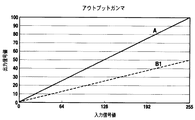
記録デューティーが100%未満の場合には、記録データの入力信号値を補正した後の出力信号値を用いて記録をする。この補正は、通常、アウトプットガンマ補正と呼ばれ、入力信号値に対して画像の記録濃度が比例するように補正するものである。図6中のAは、本例の通常記録時におけるアウトプットガンマ補正値である。実際には、用紙に対するドットのにじみなどを考慮し、アウトプットガンマ補正値は、図6中の下方に凸のカーブを描くような曲線上の値となる。ここでは説明の簡略化のために、アウトプットガンマの補正曲線を直線として説明する。アウトプットガンマ補正された出力信号はディザや誤差拡散などの量子化処理がなされ、その処理後のデータに基づき、インクが吐出されて画像が記録される。 When the recording duty is less than 100%, recording is performed using the output signal value after correcting the input signal value of the recording data. This correction is generally called output gamma correction and is performed so that the recording density of the image is proportional to the input signal value. A in FIG. 6 is an output gamma correction value during normal recording in this example. Actually, the output gamma correction value is a value on a curve that draws a downward convex curve in FIG. 6 in consideration of dot blurring on the paper. Here, for simplicity of explanation, the output gamma correction curve will be described as a straight line. The output signal subjected to output gamma correction is subjected to quantization processing such as dithering and error diffusion, and ink is ejected and an image is recorded based on the processed data.
図7は、記録動作を説明するためのフローチャートである。 FIG. 7 is a flowchart for explaining the recording operation.
記録装置に対して記録開始が指示され、被記録媒体、記録品位、記録画像、インク残量などの記録条件により、間引き記録を行うか否かを判断する(ステップS1)。間引き記録でない場合には、ドットを間引かない通常の記録(通常記録)を行う。間引き記録である場合、ブラックインクによって記録すべきドットに関しては、アウトプットガンマ補正により記録濃度を下げて、記録すべきドットを間引く(ステップS3)。図6中のB1は、ドットを50%間引くためのアウトプットガンマ補正値の一例である。また、カラーインクによって記録すべきドットに関しては、図4(b)のように基本格子に2ドット記録すべきところを図8(c)のように1ドットに減らして、50%の間引き処理をする(ステップS4)。このように、ブラックインクおよびカラーインクのドットの間引き処理をした後に、間引き記録を行う(ステップS5)。 The recording apparatus is instructed to start recording, and it is determined whether or not to perform thinning recording based on recording conditions such as a recording medium, recording quality, recorded image, and remaining ink amount (step S1). If not thinning recording, normal recording (normal recording) without thinning dots is performed. In the case of thinning recording, for the dots to be recorded with black ink, the recording density is lowered by output gamma correction, and the dots to be recorded are thinned (step S3). B1 in FIG. 6 is an example of an output gamma correction value for thinning out dots by 50%. Further, with respect to dots to be recorded with color ink, a place where two dots should be recorded on the basic grid as shown in FIG. 4B is reduced to one dot as shown in FIG. (Step S4). As described above, after the thinning process of the black ink and the color ink, the thinning recording is performed (step S5).
図6中のアウトプットガンマ補正値B1を用いることにより、図5(a)のような記録デューティー100%のブラックインクのベタ画像は、その記録ドットが図9(a)のように50%間引かれて記録されることになる。その場合には、図8(a),(b)のように、基本格子に対してブラックインクの1ドットまたは0ドットが記録されることになる。また、図5(b)のような記録デューティー100%のカラーインクのベタ画像は、その記録ドットが図9(b)のように50%間引かれて記録されることになる。 By using the output gamma correction value B1 in FIG. 6, a solid image of black ink having a recording duty of 100% as shown in FIG. 5A has a recording dot of 50% as shown in FIG. 9A. It will be drawn and recorded. In this case, as shown in FIGS. 8A and 8B, 1 dot or 0 dot of black ink is recorded on the basic lattice. Further, a solid image of color ink having a recording duty of 100% as shown in FIG. 5B is recorded with the recording dots thinned out by 50% as shown in FIG. 9B.
このように、ブラックインクの記録ドットに関しては、アウトプットガンマ補正による間引き処理であるため、基本格子に1ドットしか記録しない場合でも間引き記録が可能になる。また、カラーインクの記録ドットに関しては、間引き記録した場合にも基本格子に対して少なくとも1ドット以上記録されるため、画像劣化を抑えることができる。 As described above, since the black ink recording dots are thinning out by output gamma correction, thinning recording is possible even when only one dot is recorded in the basic lattice. In addition, with regard to the recording dots of color ink, at least one dot or more is recorded on the basic lattice even when thinning recording is performed, so that image deterioration can be suppressed.
本実施形態においては、アウトプットガンマ補正を用いた間引き処理と、基本格子に対するドットの記録数を減らすドット間引き処理を行うための2つの間引き手段を備え、ブラックインクのドットに関しては前者の間引き手段を用いて間引き記録し、カラーインクのドットに関しては後者の間引き手段を用いて間引き記録をする。この結果、1記録画素(基本格子)に対して1ドットしか記録しないブラックインクの記録ドットに関しても間引き記録を行うことができ、またカラーインクの記録ドットに関しては、カラー画像の画質の劣化を最小限に抑えた間引き記録を行うことができた。 The present embodiment includes two thinning means for performing thinning processing using output gamma correction and dot thinning processing for reducing the number of dots recorded on the basic lattice. For the black ink dots, the former thinning means is provided. Is used for thinning out recording, and the color ink dots are thinned out using the latter thinning means. As a result, it is possible to perform thinning recording even for black ink recording dots that record only one dot for one recording pixel (basic grid), and for color ink recording dots, degradation of color image quality is minimized. The thinning-out recording can be performed to a minimum.
(第2の実施形態)
図10から図14は、上述したインクジェット記録装置にも適応可能な本発明の第2の実施形態を説明するための図である。
(Second Embodiment)
10 to 14 are diagrams for explaining a second embodiment of the present invention that can be applied to the above-described ink jet recording apparatus.
図10は、通常記録の際に形成されるドットの説明図である。本実施形態では、ブラックインクに関しては、そのインクを用いた画像の記録速度を重視する観点から、図10(a)のようにドット径を大きくすべく吐出量30plとする。記録デューティーが100%均一のときは、図11(a)のように記録解像度600dpiの基本格子内に1ドットを形成して、ブラックインクのベタ画像を記録する。一方、カラーインクに関しては、それを用いた記録画像の階調性や粒状性を重視する観点から、高解像度で記録を行う。すなわち、図10(a)のように、600dpiの画像データを1200dpiの2×2のドットパターンに展開し、カラーインクのドット径を小さくすべく吐出量を5plとする。記録デューティーが100%均一のときは、図11(b)のように1200dpiの基本格子内に1ドットを形成して、カラーインクのベタ画像を記録する。 FIG. 10 is an explanatory diagram of dots formed during normal recording. In this embodiment, with respect to black ink, from the viewpoint of emphasizing the recording speed of an image using the ink, the discharge amount is set to 30 pl to increase the dot diameter as shown in FIG. When the recording duty is 100% uniform, as shown in FIG. 11A, one dot is formed in a basic grid with a recording resolution of 600 dpi, and a solid image of black ink is recorded. On the other hand, color ink is recorded at high resolution from the viewpoint of emphasizing the gradation and graininess of a recorded image using the color ink. That is, as shown in FIG. 10A, 600 dpi image data is developed into a 2 × 2 dot pattern of 1200 dpi, and the discharge amount is set to 5 pl to reduce the dot diameter of the color ink. When the recording duty is 100% uniform, one dot is formed in a 1200 dpi basic lattice as shown in FIG. 11B, and a solid image of color ink is recorded.
図12中のAは、本例の通常記録時におけるアウトプットガンマ補正値である。本例の場合、ブラックインクのドットに関しては、図12中の補正値Aの60%に相当するアウトプットガンマ補正値B2を用いることによって、間引き率40%の記録デューティー60%とする。また、カラーインクのドットに関しては、600dpiの画像データを1200dpiの2×2のドットパターンに展開する際に、1200dpiの2×2のマス目内に4つ形成すべきドット(図10(b)参照)を図13(c)のように半分の2つに間引くパターン(インデックスパターン)を用いて、記録デューティー50%の記録をする。 A in FIG. 12 is an output gamma correction value during normal recording in this example. In the case of this example, with respect to the dots of black ink, the output duty gamma correction value B2 corresponding to 60% of the correction value A in FIG. As for the color ink dots, when the 600 dpi image data is developed into a 1200 × 2 2 × 2 dot pattern, four dots should be formed in a 1200 × 2 × 2 square (FIG. 10B). 13), a recording with a recording duty of 50% is performed using a pattern (index pattern) that is thinned into two half as shown in FIG.
図12中のアウトプットガンマ補正値B2を用いることにより、図11(a)のような記録デューティー100%のブラックインクのベタ画像は、そのブラックインクのドットが図14(a)のように間引かれて記録されることになる。その場合には、図13(a),(b)のように、基本格子に対してブラックインクの1ドットまたは0ドットが記録されることになる。また、図10(b)のような記録デューティー100%のカラーインクのベタ画像は、そのカラーインクのドットが図14(b)のように50%間引かれて記録されることになる。 By using the output gamma correction value B2 in FIG. 12, a solid image of black ink having a recording duty of 100% as shown in FIG. 11A has a black ink dot as shown in FIG. 14A. It will be drawn and recorded. In that case, as shown in FIGS. 13A and 13B, 1 dot or 0 dot of black ink is recorded on the basic lattice. Further, a solid image of color ink having a recording duty of 100% as shown in FIG. 10B is recorded with the dots of the color ink thinned out by 50% as shown in FIG. 14B.
本実施形態においては、アウトプットガンマ補正を用いた間引き処理と、インデックスパターンを用いた間引き処理を行うための2つの間引き手段を備え、ブラックインクの記録ドットに関しては前者の間引き手段を用いて間引き記録し、カラーインクの記録ドットに関しては後者の間引き手段を用いて間引き記録をする。この結果、1記録画素(基本格子)に対して1ドットしか記録しないブラックインクの記録ドットに関しても間引き記録を行うことができ、またカラーインクの記録ドットに関しては、カラー画像の画質の劣化を最小限に抑えた間引き記録を行うことができた。 In the present embodiment, two thinning means for performing thinning processing using output gamma correction and thinning processing using an index pattern are provided, and black ink recording dots are thinned using the former thinning means. Recording is performed, and the recording dots of the color ink are thinned out by using the latter thinning means. As a result, it is possible to perform thinning recording even for black ink recording dots that record only one dot for one recording pixel (basic grid), and for color ink recording dots, degradation of color image quality is minimized. The thinning-out recording can be performed to a minimum.
(その他)
カラーインクのドットの間引き方式として、第1の実施形態においては基本格子内におけるドット数を減らすドット間引き方式を採用し、第2の実施形態においては、インデックスパターンを用いた間引き方式を採用した。前者の間引き方式による間引き率は、基本格子1つ当たりのドット数の逆数(第1の実施形態の場合は50%(=1/2))の倍数となり、後者の間引き方式による間引き率は、入力画像の基本格子に対するインデックスパターンの大きさの逆数(第2の実施形態の場合は25%(=1/4)の倍数となる。一方、ブラックインクのドットに関しては、アウトプットガンマ補正によって間引くため、濃度を自由に変更することができる。ブラックインクによって記録するテキスト(文字)を判別しやすくするためには、ブラックインクによる記録デューティーをカラーインクによる記録デューティーと同等かそれ以上とすることが望ましい。言い換えれば、ブラックインクのドットの間引き率に対して、カラーインクのドットの間引き率が同等かそれ以上であることが望ましい。第1の実施形態の場合、ブラックインクとカラーインクのドットの間引き率は同等の50%であり、また第2の実施形態の場合、ブラックインクのドットの間引き率は40%、かつカラーインクのドットの間引き率は50%である。
(Other)
As the color ink dot thinning method, the first embodiment employs a dot thinning method that reduces the number of dots in the basic lattice, and the second embodiment employs a thinning method using an index pattern. The thinning rate by the former thinning method is a multiple of the reciprocal of the number of dots per basic grid (in the first embodiment, 50% (= 1/2)), and the thinning rate by the latter thinning method is The reciprocal of the size of the index pattern with respect to the basic lattice of the input image (in the second embodiment, it is a multiple of 25% (= 1/4). On the other hand, the black ink dots are thinned out by output gamma correction. In order to make it easier to distinguish text (characters) recorded with black ink, the recording duty of black ink should be equal to or higher than that of color ink. In other words, the color ink dot thinning rate is the same as the black ink dot thinning rate. In the case of the first embodiment, the thinning ratio of the black ink and the color ink is equal to 50%, and in the case of the second embodiment, the black ink is thinned out. The rate is 40%, and the color ink dot thinning rate is 50%.
また、ブラックインクとカラーインクのドットの間引き率の関係は、上述した関係のみに特定されず任意に設定することができる。例えば、ブラックインクとカラーインクの特性の差、記録画像の種類(テキストやカラー画像等)などに応じて、最適に設定することができる。 Further, the relationship between the thinning rates of the black ink and the color ink dots is not limited to the above-described relationship and can be arbitrarily set. For example, it can be set optimally according to the difference in characteristics between black ink and color ink, the type of recorded image (text, color image, etc.), and the like.
また、上述した実施形態においては、ブラックインクを600dpiの記録格子に対して1ドット記録する場合について説明した。この場合において、ブラックインクによって記録するテキスト(文字)を判別しやすくするように、上述した第1、第2の実施形態におけるカラーインクのドットの間引き方式を用いて記録デューティーを調節することは困難である。本発明は、ブラックインクのドットを入力1画素(入力画像データの記録解像度における基本格子に対応する)に対して複数記録する場合にも有効であり、その場合には、上述したようなアウトプットガンマ補正による間引きの他、上述した第1、第2の実施形態におけるカラーインクのドットの間引き方式を用いることもできる。要は、ブラックインクとカラーインクの特性などに応じて、それらのドットの間引き方式を異ならせることができればよい。 In the above-described embodiment, the case has been described in which black ink is recorded by one dot on a 600 dpi recording grid. In this case, it is difficult to adjust the recording duty by using the color ink dot thinning method in the first and second embodiments described above so that the text (characters) recorded by the black ink can be easily identified. It is. The present invention is also effective when a plurality of black ink dots are recorded for one input pixel (corresponding to the basic grid in the recording resolution of the input image data). In addition to thinning by gamma correction, the above-described thinning method of color ink dots in the first and second embodiments can also be used. In short, it suffices if the dot thinning method can be made different depending on the characteristics of the black ink and the color ink.
なお、本発明は、複数の機器(例えばホストコンピュータ、インタフェイス機器、リーダ、プリンタなど)から構成されるシステム、あるいは一つの機器からなる装置(例えば、複写機、ファクシミリ装置など)にも適用することができる。 The present invention is also applicable to a system composed of a plurality of devices (for example, a host computer, an interface device, a reader, a printer, etc.) or a device composed of a single device (for example, a copier, a facsimile machine, etc.). be able to.
また、本発明の目的は、前述した実施形態の機能を実現するソフトウェアのプログラムコードを記録した記憶媒体(または記録媒体)を、システムあるいは装置に供給し、そのシステムあるいは装置のコンピュータ(またはCPUやMPU)が記憶媒体に格納されたプログラムコードを読み出し実行することによっても達成される。この場合、記憶媒体から読み出されたプログラムコード自体が前述した実施形態の機能を実現することになり、そのプログラムコード自体およびプログラムコードを記憶した記憶媒体は本発明を構成することになる。 Another object of the present invention is to supply a storage medium (or recording medium) in which a program code of software that realizes the functions of the above-described embodiments is recorded to a system or apparatus, and the computer (or CPU or CPU) of the system or apparatus. (MPU) can also be achieved by reading and executing the program code stored in the storage medium. In this case, the program code itself read from the storage medium realizes the functions of the above-described embodiments, and the program code itself and the storage medium storing the program code constitute the present invention.
また、コンピュータが読み出したプログラムコードを実行することにより、前述した実施形態の機能が実現されるだけでなく、そのプログラムコードの指示に基づき、コンピュータ上で稼働しているオペレーティングシステム(OS)などが実際の処理の一部または全部を行い、その処理によって前述した実施形態の機能が実現される場合も含まれる。 Further, by executing the program code read by the computer, not only the functions of the above-described embodiments are realized, but also an operating system (OS) running on the computer based on the instruction of the program code. A case where part or all of the actual processing is performed and the functions of the above-described embodiments are realized by the processing is also included.
さらに、記憶媒体から読み出されたプログラムコードが、コンピュータに挿入された機能拡張カードやコンピュータに接続された機能拡張ユニットに備わるメモリに書込まれた後、そのプログラムコードの指示に基づき、その機能拡張カードや機能拡張ユニットに備わるCPUなどが実際の処理の一部または全部を行い、その処理によって前述した実施形態の機能が実現される場合も含まれる。 Furthermore, after the program code read from the storage medium is written into a memory provided in a function expansion card inserted into the computer or a function expansion unit connected to the computer, the function is determined based on the instruction of the program code. The case where the CPU of the expansion card or the function expansion unit performs part or all of the actual processing and the functions of the above-described embodiments are realized by the processing is also included.
100 CPU
101 ROM
102 RAM
H1001 記録ヘッド
100 CPU
101 ROM
102 RAM
H1001 Recording head
Claims (6)
最終的な記録画像のブラックインクの濃度を低くするときに、前記ブラックインクに対応する多値の記録データが記録画像のブラックインクの濃度と比例関係となるように前記ブラックインクに対応する多値の記録データを補正する処理において、前記ブラックインクに対応する多値の記録データを変更してブラックインクのドット数を少なくするブラック記録制御手段と、
最終的な記録画像のカラーインクの濃度を低くするときに、1記録画素に形成するカラーインクのドットの数を定めた前記カラーインクに対応する多値の記録データを変更してカラーインクのドット数を少なくするカラー記録制御手段と、
を備えることを特徴とする記録装置。 In a recording apparatus capable of recording an image by forming dots of black ink and color ink on a recording medium based on binary recording data generated from multi- value recording data ,
The multi-value corresponding to the black ink is set so that the multi-value recording data corresponding to the black ink has a proportional relationship with the density of the black ink in the recorded image when the density of the black ink in the final recorded image is lowered. Black recording control means for reducing the number of dots of the black ink by changing the multi-value recording data corresponding to the black ink in the process of correcting the recording data of
When the density of the color ink in the final recorded image is lowered , the multi-valued recording data corresponding to the color ink in which the number of color ink dots formed on one recording pixel is determined is changed to change the color ink dot Color recording control means for reducing the number,
A recording apparatus comprising:
最終的な記録画像のブラックインクの濃度を低くするときに、前記ブラックインクに対応する多値の記録データが記録画像のブラックインクの濃度と比例関係となるように前記ブラックインクに対応する多値の記録データを補正する処理において、前記ブラックインクに対応する多値の記録データを変更してブラックインクのドット数を少なくするブラック記録制御手段と、The multi-value corresponding to the black ink is set so that the multi-value recording data corresponding to the black ink has a proportional relationship with the density of the black ink in the recorded image when the density of the black ink in the final recorded image is lowered. Black recording control means for reducing the number of dots of the black ink by changing the multi-value recording data corresponding to the black ink in the process of correcting the recording data of
最終的な記録画像のカラーインクの濃度を低くするときに、1記録画素に形成するカラーインクのドットの数を定めた前記カラーインクに対応する多値の記録データをドットパターンに基づいて前記カラーインクに対応する2値の記録データに変換する際にカラーインクのドット数を少なくするカラー記録制御手段と、When the density of the color ink of the final recorded image is lowered, the multi-valued recording data corresponding to the color ink in which the number of dots of the color ink formed on one recording pixel is determined is based on the dot pattern. Color recording control means for reducing the number of dots of color ink when converting into binary recording data corresponding to ink;
を備えることを特徴とする記録装置。A recording apparatus comprising:
最終的な記録画像のブラックインクの濃度を低くするときに、前記ブラックインクに対応する多値の記録データが記録画像のブラックインクの濃度と比例関係となるように前記ブラックインクに対応する多値の記録データを補正する処理において、前記ブラックインクに対応する多値の記録データを変更してブラックインクのドット数を少なくし、
最終的な記録画像のカラーインクの濃度を低くするときに、1記録画素に形成するカラーインクのドットの数を定めた前記カラーインクに対応する多値の記録データを変更してカラーインクのドット数を少なくする
ことを特徴とする記録方法。 In a recording method capable of recording an image by forming dots of black ink and color ink on a recording medium based on binary recording data generated from multi- value recording data ,
The multi-value corresponding to the black ink is set so that the multi-value recording data corresponding to the black ink has a proportional relationship with the density of the black ink in the recorded image when the density of the black ink in the final recorded image is lowered. in the process of correcting the recording data, to reduce the number of dots a black ink by changing the multi-valued print data corresponding to the black ink,
When the density of the color ink of the final recorded image is lowered, the multi-valued recording data corresponding to the color ink in which the number of the color ink dots to be formed in one recording pixel is changed to change the color ink dots A recording method characterized by reducing the number .
最終的な記録画像のブラックインクの濃度を低くするときに、前記ブラックインクに対応する多値の記録データが記録画像のブラックインクの濃度と比例関係となるように前記ブラックインクに対応する多値の記録データを補正する処理において、前記ブラックインクに対応する多値の記録データを変更してブラックインクのドット数を少なくし、The multi-value corresponding to the black ink is set so that the multi-value recording data corresponding to the black ink has a proportional relationship with the density of the black ink in the recorded image when the density of the black ink in the final recorded image is lowered. In the process of correcting the print data, the multi-value print data corresponding to the black ink is changed to reduce the number of black ink dots,
最終的な記録画像のカラーインクの濃度を低くするときに、1記録画素に形成するカラーインクのドットの数を定めた前記カラーインクに対応する多値の記録データをドットパターンに基づいて前記カラーインクに対応する2値の記録データに変換する際にカラーインクのドット数を少なくするWhen the density of the color ink of the final recorded image is lowered, the multi-valued recording data corresponding to the color ink in which the number of dots of the color ink formed on one recording pixel is determined is based on the dot pattern. Reduce the number of dots of color ink when converting to binary recording data corresponding to ink
ことを特徴とする記録方法。And a recording method.
Priority Applications (4)
| Application Number | Priority Date | Filing Date | Title |
|---|---|---|---|
| JP2003284384A JP4387721B2 (en) | 2003-07-31 | 2003-07-31 | Recording apparatus and recording method |
| US10/898,192 US7152948B2 (en) | 2003-07-31 | 2004-07-26 | Printing apparatus and printing method |
| CNB2004100704078A CN100434274C (en) | 2003-07-31 | 2004-08-02 | Printing apparatus and printing method |
| US11/500,884 US7264325B2 (en) | 2003-07-31 | 2006-08-09 | Printing apparatus and printing method |
Applications Claiming Priority (1)
| Application Number | Priority Date | Filing Date | Title |
|---|---|---|---|
| JP2003284384A JP4387721B2 (en) | 2003-07-31 | 2003-07-31 | Recording apparatus and recording method |
Publications (3)
| Publication Number | Publication Date |
|---|---|
| JP2005047240A JP2005047240A (en) | 2005-02-24 |
| JP2005047240A5 JP2005047240A5 (en) | 2007-03-08 |
| JP4387721B2 true JP4387721B2 (en) | 2009-12-24 |
Family
ID=34101096
Family Applications (1)
| Application Number | Title | Priority Date | Filing Date |
|---|---|---|---|
| JP2003284384A Expired - Fee Related JP4387721B2 (en) | 2003-07-31 | 2003-07-31 | Recording apparatus and recording method |
Country Status (3)
| Country | Link |
|---|---|
| US (2) | US7152948B2 (en) |
| JP (1) | JP4387721B2 (en) |
| CN (1) | CN100434274C (en) |
Families Citing this family (12)
| Publication number | Priority date | Publication date | Assignee | Title |
|---|---|---|---|---|
| JP4714906B2 (en) * | 2004-08-18 | 2011-07-06 | コニカミノルタエムジー株式会社 | Image recording method and image recording apparatus |
| US20060103857A1 (en) * | 2004-11-17 | 2006-05-18 | Lexmark International, Inc. | Method of reducing a consumption of imaging substance when forming an image |
| JP4137935B2 (en) * | 2005-11-11 | 2008-08-20 | シャープ株式会社 | Image processing apparatus, pattern detection method, program, and recording medium |
| JP2007160815A (en) * | 2005-12-16 | 2007-06-28 | Seiko Epson Corp | Printer, printing method, printing system and program |
| JP4315458B2 (en) * | 2006-03-31 | 2009-08-19 | キヤノン株式会社 | Inkjet recording apparatus, image processing apparatus, and image processing method |
| US7838865B2 (en) * | 2006-12-22 | 2010-11-23 | Palo Alto Research Center Incorporated | Method for aligning elongated nanostructures |
| US7838933B2 (en) * | 2006-12-22 | 2010-11-23 | Palo Alto Res Ct Inc | Printing method for high performance electronic devices |
| JP5131090B2 (en) * | 2007-11-16 | 2013-01-30 | セイコーエプソン株式会社 | Image processing apparatus, image processing method, and image processing program |
| JP2010012635A (en) * | 2008-07-01 | 2010-01-21 | Canon Inc | Recording device |
| JP5665453B2 (en) * | 2009-11-30 | 2015-02-04 | キヤノン株式会社 | Image processing apparatus and image processing method |
| CN103202691B (en) * | 2013-03-21 | 2014-12-10 | 深圳市理邦精密仪器股份有限公司 | Method and device for improving electrocardiogram waveform data printing efficiency |
| US9667828B2 (en) * | 2015-03-13 | 2017-05-30 | Kabushiki Kaisha Toshiba | Printing method |
Family Cites Families (6)
| Publication number | Priority date | Publication date | Assignee | Title |
|---|---|---|---|---|
| JPH06139348A (en) | 1992-10-28 | 1994-05-20 | Canon Inc | Image processing method and image processor |
| EP1162568B1 (en) * | 1993-05-27 | 2007-09-12 | Canon Kabushiki Kaisha | Ink jet recording method and apparatus |
| JP3919874B2 (en) | 1996-04-05 | 2007-05-30 | セイコーエプソン株式会社 | Inkjet recording device with high-speed printing mode |
| JP2000108387A (en) * | 1998-10-03 | 2000-04-18 | Copyer Co Ltd | Ink jet image forming apparatus |
| JP4018398B2 (en) * | 2001-02-09 | 2007-12-05 | キヤノン株式会社 | Color ink jet recording apparatus and color ink jet recording method |
| US7253923B2 (en) * | 2001-03-15 | 2007-08-07 | Seiko Epson Corporation | Image processing apparatus |
-
2003
- 2003-07-31 JP JP2003284384A patent/JP4387721B2/en not_active Expired - Fee Related
-
2004
- 2004-07-26 US US10/898,192 patent/US7152948B2/en not_active Expired - Fee Related
- 2004-08-02 CN CNB2004100704078A patent/CN100434274C/en not_active Expired - Fee Related
-
2006
- 2006-08-09 US US11/500,884 patent/US7264325B2/en not_active Expired - Fee Related
Also Published As
| Publication number | Publication date |
|---|---|
| US20050024407A1 (en) | 2005-02-03 |
| JP2005047240A (en) | 2005-02-24 |
| CN100434274C (en) | 2008-11-19 |
| US20060268039A1 (en) | 2006-11-30 |
| US7152948B2 (en) | 2006-12-26 |
| US7264325B2 (en) | 2007-09-04 |
| CN1579765A (en) | 2005-02-16 |
Similar Documents
| Publication | Publication Date | Title |
|---|---|---|
| US7264325B2 (en) | Printing apparatus and printing method | |
| JP4227627B2 (en) | Inkjet recording apparatus and image processing method | |
| US6846066B2 (en) | Recording apparatus for recording image by expanding the image in dot pattern | |
| JP4603820B2 (en) | Recording apparatus and recording method | |
| EP1396345B1 (en) | Ink-jet printing method, printing system, ink-jet printing apparatus, print data generating method, program and printer driver | |
| US20040141020A1 (en) | Ink-jet printing method and apparatus | |
| JP4965992B2 (en) | Inkjet recording apparatus, inkjet recording method, program, and storage medium | |
| JP4579557B2 (en) | Recording apparatus, control method therefor, and program | |
| US8976416B2 (en) | Image processing apparatus and method thereof | |
| JP2006001051A (en) | Inkjet recording method and inkjet recorder | |
| JP2006168073A (en) | Inkjet recording system | |
| JP2006001052A (en) | Sheet face preliminary discharging method and inkjet recorder | |
| JP2010130303A (en) | Print controller, printing apparatus, print control method, and computer program | |
| JP2008142901A (en) | Image formation controller and control method of image formation controller | |
| JP2006305993A (en) | Inkjet recorder, apparatus for supplying recorder with image data, and method for controlling recorder | |
| JP4424726B2 (en) | Inkjet recording apparatus and inkjet recording method | |
| JP2005032258A (en) | Printing method and printer using non-uniform resolution per raster | |
| JP4411028B2 (en) | Inkjet recording apparatus and inkjet recording system | |
| US8711424B2 (en) | Image processing apparatus, image printing apparatus and printing data generation method | |
| JP3915521B2 (en) | Printing that suppresses blurring of contours | |
| JP2009101667A (en) | Recording device and control method of recording device | |
| US20220318580A1 (en) | Apparatus, method, and storage medium | |
| JP2006224616A (en) | Recording method and recording system | |
| JP2004209765A (en) | Recorder and method of recording | |
| JP4289232B2 (en) | Image processing using threshold matrix |
Legal Events
| Date | Code | Title | Description |
|---|---|---|---|
| A621 | Written request for application examination |
Free format text: JAPANESE INTERMEDIATE CODE: A621 Effective date: 20060614 |
|
| A521 | Request for written amendment filed |
Free format text: JAPANESE INTERMEDIATE CODE: A523 Effective date: 20070123 |
|
| A977 | Report on retrieval |
Free format text: JAPANESE INTERMEDIATE CODE: A971007 Effective date: 20090518 |
|
| A131 | Notification of reasons for refusal |
Free format text: JAPANESE INTERMEDIATE CODE: A131 Effective date: 20090522 |
|
| A521 | Request for written amendment filed |
Free format text: JAPANESE INTERMEDIATE CODE: A523 Effective date: 20090721 |
|
| TRDD | Decision of grant or rejection written | ||
| A01 | Written decision to grant a patent or to grant a registration (utility model) |
Free format text: JAPANESE INTERMEDIATE CODE: A01 Effective date: 20090929 |
|
| A01 | Written decision to grant a patent or to grant a registration (utility model) |
Free format text: JAPANESE INTERMEDIATE CODE: A01 |
|
| A61 | First payment of annual fees (during grant procedure) |
Free format text: JAPANESE INTERMEDIATE CODE: A61 Effective date: 20091001 |
|
| R150 | Certificate of patent or registration of utility model |
Ref document number: 4387721 Country of ref document: JP Free format text: JAPANESE INTERMEDIATE CODE: R150 Free format text: JAPANESE INTERMEDIATE CODE: R150 |
|
| FPAY | Renewal fee payment (event date is renewal date of database) |
Free format text: PAYMENT UNTIL: 20121009 Year of fee payment: 3 |
|
| FPAY | Renewal fee payment (event date is renewal date of database) |
Free format text: PAYMENT UNTIL: 20131009 Year of fee payment: 4 |
|
| LAPS | Cancellation because of no payment of annual fees |