JP4386835B2 - System and method for acquiring and maintaining high resistance sticking in patch clamp recording - Google Patents
System and method for acquiring and maintaining high resistance sticking in patch clamp recording Download PDFInfo
- Publication number
- JP4386835B2 JP4386835B2 JP2004531155A JP2004531155A JP4386835B2 JP 4386835 B2 JP4386835 B2 JP 4386835B2 JP 2004531155 A JP2004531155 A JP 2004531155A JP 2004531155 A JP2004531155 A JP 2004531155A JP 4386835 B2 JP4386835 B2 JP 4386835B2
- Authority
- JP
- Japan
- Prior art keywords
- cell
- opening
- channel
- substrate
- cells
- Prior art date
- Legal status (The legal status is an assumption and is not a legal conclusion. Google has not performed a legal analysis and makes no representation as to the accuracy of the status listed.)
- Expired - Fee Related
Links
Images


Classifications
-
- G—PHYSICS
- G01—MEASURING; TESTING
- G01N—INVESTIGATING OR ANALYSING MATERIALS BY DETERMINING THEIR CHEMICAL OR PHYSICAL PROPERTIES
- G01N33/00—Investigating or analysing materials by specific methods not covered by groups G01N1/00 - G01N31/00
- G01N33/48—Biological material, e.g. blood, urine; Haemocytometers
- G01N33/50—Chemical analysis of biological material, e.g. blood, urine; Testing involving biospecific ligand binding methods; Immunological testing
- G01N33/53—Immunoassay; Biospecific binding assay; Materials therefor
- G01N33/543—Immunoassay; Biospecific binding assay; Materials therefor with an insoluble carrier for immobilising immunochemicals
- G01N33/54366—Apparatus specially adapted for solid-phase testing
- G01N33/54373—Apparatus specially adapted for solid-phase testing involving physiochemical end-point determination, e.g. wave-guides, FETS, gratings
-
- C—CHEMISTRY; METALLURGY
- C12—BIOCHEMISTRY; BEER; SPIRITS; WINE; VINEGAR; MICROBIOLOGY; ENZYMOLOGY; MUTATION OR GENETIC ENGINEERING
- C12M—APPARATUS FOR ENZYMOLOGY OR MICROBIOLOGY; APPARATUS FOR CULTURING MICROORGANISMS FOR PRODUCING BIOMASS, FOR GROWING CELLS OR FOR OBTAINING FERMENTATION OR METABOLIC PRODUCTS, i.e. BIOREACTORS OR FERMENTERS
- C12M35/00—Means for application of stress for stimulating the growth of microorganisms or the generation of fermentation or metabolic products; Means for electroporation or cell fusion
- C12M35/02—Electrical or electromagnetic means, e.g. for electroporation or for cell fusion
-
- G—PHYSICS
- G01—MEASURING; TESTING
- G01N—INVESTIGATING OR ANALYSING MATERIALS BY DETERMINING THEIR CHEMICAL OR PHYSICAL PROPERTIES
- G01N33/00—Investigating or analysing materials by specific methods not covered by groups G01N1/00 - G01N31/00
- G01N33/48—Biological material, e.g. blood, urine; Haemocytometers
- G01N33/483—Physical analysis of biological material
- G01N33/487—Physical analysis of biological material of liquid biological material
- G01N33/48707—Physical analysis of biological material of liquid biological material by electrical means
- G01N33/48728—Investigating individual cells, e.g. by patch clamp, voltage clamp
Landscapes
- Health & Medical Sciences (AREA)
- Life Sciences & Earth Sciences (AREA)
- Engineering & Computer Science (AREA)
- Biomedical Technology (AREA)
- Chemical & Material Sciences (AREA)
- Immunology (AREA)
- Physics & Mathematics (AREA)
- Urology & Nephrology (AREA)
- Biochemistry (AREA)
- Hematology (AREA)
- Molecular Biology (AREA)
- Biotechnology (AREA)
- General Health & Medical Sciences (AREA)
- Microbiology (AREA)
- Genetics & Genomics (AREA)
- General Physics & Mathematics (AREA)
- Organic Chemistry (AREA)
- Pathology (AREA)
- Medicinal Chemistry (AREA)
- Cell Biology (AREA)
- Food Science & Technology (AREA)
- Zoology (AREA)
- Analytical Chemistry (AREA)
- Bioinformatics & Cheminformatics (AREA)
- Wood Science & Technology (AREA)
- Sustainable Development (AREA)
- Electromagnetism (AREA)
- General Engineering & Computer Science (AREA)
- Biophysics (AREA)
- Apparatus Associated With Microorganisms And Enzymes (AREA)
- Investigating Or Analysing Biological Materials (AREA)
- Measuring Or Testing Involving Enzymes Or Micro-Organisms (AREA)
- Investigating Or Analyzing Materials By The Use Of Electric Means (AREA)
Description
本出願は2002年8月21日に出願した米国仮特許出願第60/404,886号に対する35U.S.C.119(e)に基づき優先権を主張し、その全内容がここに参照され援用される。 This application is 35 U.S. to US Provisional Patent Application No. 60 / 404,886, filed on August 21, 2002. S. C. Claim priority based on 119 (e), the entire contents of which are hereby incorporated by reference.
本発明は、パッチクランプ記録のための電極区画に細胞を連結する絶縁表面中の開口部と細胞との間の高電気抵抗固着を獲得し及び/又は維持するシステム及び方法に関する。ある態様において、その表面はパッチクランプマイクロピペットの開口部である。別の態様において、開口部はチップ上のパッチクランプ装置中の隙間(aperture)である。 The present invention relates to a system and method for obtaining and / or maintaining high electrical resistance adhesion between an opening in an insulating surface that couples a cell to an electrode compartment for patch clamp recording and the cell. In certain embodiments, the surface is an opening of a patch clamp micropipette. In another aspect, the opening is an aperture in the patch clamp device on the chip.
イオン−チャネルは重要な治療標的である。神経単位の伝達、心機能及び記憶は全てリガンド−開閉及び電圧−開閉イオン−チャネルの機能に決定的に依存している。加えて、心臓、消化管及び脳のような多くの器官における広い範囲の慢性及び急性の病態生理学的状態はイオンチャネルによって生じる。実際に、多くの現存する薬はイオン−チャネルに直接的又は間接的に関係がある受容体と結合する。例えば、抗−精神病の薬はドーパミン作動性、セロトニン作動性、コリン作動性及びグルタミン酸作動性の神経伝達に従事する受容体と相互作用する。 Ion-channels are important therapeutic targets. Neuronal transmission, cardiac function and memory are all critically dependent on ligand-switching and voltage-switching ion-channel functions. In addition, a wide range of chronic and acute pathophysiological conditions in many organs such as the heart, gastrointestinal tract and brain are caused by ion channels. In fact, many existing drugs bind to receptors that are directly or indirectly related to ion-channels. For example, anti-psychotic drugs interact with receptors that engage in dopaminergic, serotonergic, cholinergic and glutamatergic neurotransmission.
電圧クランプ法は細胞中のイオンチャネル活性を測定するための他の如何なる技術より優れている(例えば、ネエル及びザクマン,Nature260:799−802;ハミル等,1981,Pflugers Arch391:85−100;ザクマン及びネエル,1983,Single−Channel Recordingの中のpp.37−52,Eds.B.ザクマン及びE.ネエル.ニューヨーク及びロンドン,プレナムプレス参照)。 The voltage clamp method is superior to any other technique for measuring ion channel activity in cells (eg, Neel and Zakuman, Nature 260 : 799-802; Hamil et al., 1981, Pflugers Arch 391 : 85-100; Zakuman and Neel, 1983, pp. 37-52 in Single-Channel Recording, Eds. B. Zakuman and E. Neel, New York and London, Plenum Press).
電圧クランプ技術の間で、パッチクランプはpA範囲の電流を測定するために最も好適である(例えば、ネエル及びザクマン,1976,supra;ハミル等,1981,supra,ネエル及びザクマン,1983,supra参照)。パッチクランプ技術の変化は、当技術分野において知られているような細胞全体記録、インサイド−アウト記録、アウトサイド−アウト記録、及び穿孔されたパッチ記録のように利用されることが可能である。 Among voltage clamp techniques, patch clamps are most suitable for measuring currents in the pA range (see, eg, Neel and Zakuman, 1976, supra; Hamil et al., 1981, supra, Neel and Zakuman, 1983, supra). . Changes in patch clamp technology can be utilized such as whole cell recording, inside-out recording, outside-out recording, and perforated patch recording as known in the art.
細胞全体記録において、細胞内部及び電極溶液の間の電気的接続(及び化学的経路)を確立するために電極の先端を覆う細胞膜は吸引によって破裂されると信じられている。電極溶液は細胞中の細胞質の量に比べて非常に過剰な量であるため(約10μl対約1pl)、一定の受容体/イオン−チャネル複合体の膜貫通型のイオンの流れの方向及び規模を制御する手段を条件に、電極溶液中のイオン種を変化させることは細胞膜を越えて濃度勾配を生み出す。 In whole cell recording, it is believed that the cell membrane covering the tip of the electrode to rupture by suction to establish an electrical connection (and chemical pathway) between the cell interior and the electrode solution. The direction and magnitude of the transmembrane ion flow of a given receptor / ion-channel complex because the electrode solution is in excess of the amount of cytoplasm in the cell (about 10 μl vs. about 1 pl). Changing the ionic species in the electrode solution on the condition of controlling the flow rate creates a concentration gradient across the cell membrane.
インサイド−アウト、及びアウトサイド−アウトパッチクランプ構造において、細胞質環境は細胞全体からの膜パッチの切除によって喪失する(例えば,ネエル及びザクマン,1976,supra;ザクマン及びネエル,1983,supra参照)。インサイド−アウト及びアウトサイド−アウト構造の両者におけるパッチの切除を得るために、細胞は望ましくは細胞皿又は記録チャンバの底部へ付着される。強く分離された細胞の場合、例えばポリ−L−リジンを、チャンバの底部と細胞を固定するために使用することが可能である。 In inside-out and outside-out patch clamp structures, the cytoplasmic environment is lost by excision of membrane patches from whole cells (see, eg, Neel and Zakuman, 1976, supra; see Zakuman and Neel, 1983, supra). To obtain ablation of patches in both the inside-out and outside-out structures, the cells are desirably attached to the bottom of the cell dish or recording chamber. In the case of strongly separated cells, for example, poly-L-lysine can be used to fix the cell to the bottom of the chamber.
インサイド−アウト構造は膜の細胞質側を記録チャンバ中の溶液へさらすことを可能とする。従って、それは単一−チャネルの度合いにおける第二−メッセンジャー活性化イオン−チャネルの開閉特性を研究するための選択の方法である。よって、細胞質のシグナル伝達分子の効果又はイオン−チャネル機能における酵素的活性は本構造を用いて研究され得る。一方、アウトサイド−アウト構造は、パッチの細胞外の側の露呈を可能とする。従って、それはリガンド−開閉又は受容体−操作イオン−チャネルの活性を監視するために使用されることが可能である。 The inside-out structure allows the cytoplasmic side of the membrane to be exposed to the solution in the recording chamber. Thus, it is the method of choice for studying the opening and closing properties of second-messenger activated ion-channels at the single-channel degree. Thus, the effects of cytoplasmic signaling molecules or enzymatic activity in ion-channel function can be studied using this structure. On the other hand, the outside-out structure allows for the exposure of the extracellular side of the patch. It can therefore be used to monitor the activity of ligand-opening / closing or receptor-manipulating ion-channels.
一つの頻繁に使用される細胞全体構造の改質である、穿孔パッチモードもまた使用され得る(例えば,Pusch及びネエル,1988,supraの記載参照)。この技術において、穴はアンフォテリシン又はナイスタチン(例えば、Akaike等,1994,Jpn.J.Physiol.44:433−473;Falke等,1989,FEBS Lett.251:167;Bolard等,1991,Biochemistry30:5707−5715参照)のような細孔−作成蛋白質を用いて、細胞内信号伝達分子を損失することなくパッチされた細胞膜を横切る導電性の増加を生み出すために選択的に細胞膜中に作られる。定膜電位イオンチャネルを横切るイオン電流の測定に加えて、パッチクランプ技術が、公知の定電流又は時間依存性電流にて膜電圧を測定するために使用され得る。そして別の態様において、パッチクランプ技術は、開口容量槽における細胞−ベースバイオセンサーを提供し、ACモードにおけるバイオセンサーの膜を横切る膜の電気抵抗を測定することにより細胞膜における容量変化を監視するために使用されることが可能である。 A perforated patch mode, which is one frequently used modification of the whole cell structure, can also be used (see, for example, Pusch and Neel, 1988, supra). In this technique, the holes are amphotericin or nystatin (eg, Akake et al., 1994, Jpn. J. Physiol. 44 : 433-473; Falke et al., 1989, FEBS Lett. 251: 167; Borard et al., 1991, Biochemistry 30 : 5707. Using a pore-creating protein such as -5715) is selectively made in the cell membrane to produce an increase in conductivity across the patched cell membrane without loss of intracellular signaling molecules. In addition to measuring ion current across a constant membrane potential ion channel, patch clamp techniques can be used to measure membrane voltage at a known constant current or time dependent current. And in another aspect, the patch clamp technique provides a cell-based biosensor in an open volume reservoir to monitor capacitance changes in the cell membrane by measuring the electrical resistance of the membrane across the biosensor membrane in AC mode. Can be used.
パッチクランプは従来、先細のガラス製のマイクロピペットを用いて実施されている。しかしながら、近年シリコンチップのような固体基板上のパッチクランプ装置を開発することに多大な努力がなされている。概して、これらの基板は従来のパッチクランプ電極の開口部に相当する細胞の配置及び固着のための一つ以上の開口部を備えている。例えば、クレミック等は、国際公開第01/59447号パンフレットに、複数のパッチクランプ細胞にてパッチクランプ記録を実施するための複数の電極からなる平面的パッチクランプ電極配列について記載されている。 Patch clamping is conventionally performed using a tapered glass micropipette. However, much effort has been made in recent years to develop patch clamp devices on solid substrates such as silicon chips. In general, these substrates are provided with one or more openings for placement and fixation of cells corresponding to the openings of conventional patch clamp electrodes. For example, Cremic et al., In WO 01/59447, describe a planar patch clamp electrode array consisting of a plurality of electrodes for performing patch clamp recording with a plurality of patch clamp cells.
低ノイズ度合いは、パッチクランプ記録においてより良い信号対ノイズ比を提供する。パッチクランプの低ノイズ特性は、無傷の細胞の原形質膜上へガラスマイクロ電極又はパッチクランプピペットをしっかりと固着し、その結果隔離されたパッチを生じることによって達成される。ピペットと原形質膜との間の電気抵抗はバックグラウンドノイズを最小限にするために絶対不可欠であり、109オームを越えて「ギガシール」を形成すべきである。「ギガシール」形成の背後にある正確なメカニズムは議論されているが、塩−架橋、静電相互作用、及びファン・デル・ワールス力のような多様な相互作用がピペットのガラス表面及び細胞膜の脂質層中の親水性ヘッドとの間の相互作用を仲介することが提案されている(例えば、Corey及びStevens,1983,単一−チャネル記録中のpp.53−68,Eds.B.Sakmann及びE.Neher.ニューヨーク及びロンドン,プレナムプレス参照)。光学的条件の下、より高いフェムト−アンペア(10−15A)範囲における単一−チャネル電流は変化することが可能である。(例えば、電極と細胞との間の好ましくない固着によって引き起こされるような)GΩ−固着の形成を容易にするノイズを減少させるストラテジーとしては、ガラス電極の火造り又は薬剤例えばシグマコート(sigmacote)を用いたガラス電極の表面処理が挙げられるが、これらに限定されない。誘電性ノイズ及び容量性−抵抗性帯電ノイズはまた、都合のよい電極/ピペット形状を選択し、石英ガラスを使用し、そしてできるだけピペットの電荷を低めるためにピペットのガラス表面をシルガード(登録商標)(シリコン、PDMS)で被覆することにより減少することが可能である。 A low noise measure provides a better signal-to-noise ratio in patch clamp recording. The low noise properties of patch clamps are achieved by firmly anchoring a glass microelectrode or patch clamp pipette onto the intact cell plasma membrane, resulting in isolated patches. Electrical resistance between the pipette and the plasma membrane is essential in order to minimize the background noise, should form a "giga seal" more than 10 9 ohms. Although the exact mechanism behind the formation of “Gigaseal” has been discussed, a variety of interactions such as salt-crosslinking, electrostatic interactions, and van der Waals forces are responsible for lipids on the glass surface and cell membrane of pipettes. It has been proposed to mediate the interaction between the hydrophilic heads in the layer (eg Corey and Stevens, 1983, pp. 53-68, Eds. B. Sakmann and E in single-channel recording. Neher, New York and London, see Plenum Press). Under optical conditions, the single-channel current in the higher femto-ampere ( 10-15 A) range can vary. Strategies to reduce noise that facilitates the formation of GΩ-sticking (eg, caused by undesired sticking between the electrode and the cell) include glass electrode firing or chemicals such as sigmacoat. Although the surface treatment of the used glass electrode is mentioned, it is not limited to these. Dielectric noise and capacitive-resistive charging noise also select a convenient electrode / pipette shape, use quartz glass, and Sylgard® pipette glass surface to reduce pipette charge as much as possible It can be reduced by coating with (silicon, PDMS).
しかしながら、固体基板チップと従来のパッチクランプマイクロピペットとの両者に対して好ましい電気的固着特性にて付着した細胞を獲得し、維持することが困難であることは立証されている。両者の技術を備えた細胞全体記録構造を得るための典型的な成功率は約50%である。更に、記録を得るためにパッチクランプマイクロピペットに対して思い通りの位置に細胞を保持することが可能な時間は、めったに20分を越えない。 However, it has proven difficult to obtain and maintain cells attached with favorable electrical anchoring properties to both solid substrate chips and conventional patch clamp micropipettes. The typical success rate for obtaining a whole cell recording structure with both techniques is about 50%. Furthermore, the time allowed to hold the cells in the desired position relative to the patch clamp micropipette to obtain a record rarely exceeds 20 minutes.
本発明の目的及び特徴は以下の詳細な説明及び添付の図面を参照してより一層理解されることが可能である。図は実物大ではない。以下の図において、「P」は圧力を示し、「V」はボルトを示している。 The objects and features of the present invention may be better understood with reference to the following detailed description and accompanying drawings. The figure is not full scale. In the following drawings, “P” indicates pressure and “V” indicates bolt.
本発明は電極区画に細胞を連結する開口部を規定する表面と細胞との間の高電気抵抗固着を発生させるシステム及び方法を提供する。細胞膜が表面に対して固着されると、細胞膜は電極区画の内部にて電極と電気的に連通する。 The present invention provides a system and method for generating a high electrical resistance bond between a cell and a surface defining an opening connecting the cell to an electrode compartment. When the cell membrane is secured to the surface, the cell membrane is in electrical communication with the electrode inside the electrode compartment.
ある態様において、本発明は細胞を電極区画に連結する表面と細胞との間の固着を最適化する改質された表面を提供する。例えば、ある態様において、表面は非平面であり、表面に対してよりしっかりとした固着を生み出す細胞での圧迫を生み出す。望ましくは、表面は突出している。開口部を規定する表面は隙間(aperture)パッチクランプ配列装置のようなチップ上のパッチクランプ装置の一部であることが可能であり、或いはパッチクランプマイクロピペットの先端であることが可能である。望ましくは、固着が形成されたときに発生する電気抵抗は少なくとも100Mオーム、少なくとも1Gオーム、少なくとも10Gオーム、又は少なくとも100Gオームである。 In certain embodiments, the present invention provides a modified surface that optimizes adhesion between the cell and the surface connecting the cell to the electrode compartment. For example, in certain embodiments, the surface is non-planar, creating a pressure on the cell that creates a tighter bond to the surface. Desirably, the surface is protruding. The surface defining the opening can be part of a patch clamp device on a chip, such as an aperture patch clamp array device, or can be the tip of a patch clamp micropipette. Desirably, the electrical resistance generated when a bond is formed is at least 100 M ohms, at least 1 G ohms, at least 10 G ohms, or at least 100 G ohms.
本発明はまた、細胞チャンバの開口部と細胞との間に形成された固着の電気抵抗を極大化するための非平面素子からなる細胞チャンバからなるチップ上のパッチクランプ装置を提供する。この態様において、細胞チャンバは、チャンバの底部の一つ以上の電気素子、及び、細胞を分離して一つ以上の電気素子と細胞との間の直接的な接触を防止する電解質溶液を包含する電極区画を規定する。ある態様において、細胞チャンバ中の非平面素子はピラミッド型、円錐型、楕円型又はドーナツ型である。別の態様において、非平面素子は細胞を受け入れる陥凹部からなる。望ましくは、チップ上のパッチクランプ装置は、複数の細胞チャンバからなる配列装置であり、そして少なくとも一つの細胞チャンバは非平面素子からなる。より望ましくは、実質的に全ての細胞チャンバが非平面素子からなる。 The present invention also provides a patch clamp device on a chip comprising a cell chamber composed of a non-planar element for maximizing the electrical resistance of adhesion formed between the opening of the cell chamber and the cell. In this embodiment, the cell chamber includes one or more electrical elements at the bottom of the chamber and an electrolyte solution that separates the cells and prevents direct contact between the one or more electrical elements and the cells. Define the electrode compartment. In certain embodiments, the non-planar elements in the cell chamber are pyramidal, conical, elliptical or donut shaped. In another embodiment, the non-planar element consists of a recess that receives cells. Preferably, the patch clamp device on the chip is an array device composed of a plurality of cell chambers, and at least one cell chamber is composed of a non-planar element. More desirably, substantially all cell chambers are comprised of non-planar elements.
本発明の別の態様において、電極区画に細胞膜を連結する開口部を規定する表面は表面にて高電気抵抗固着の形成を最適化する表面化学を提供するように改質されている。望ましくは、表面は親水性分子からなり、或いは親水性にされるよう処理される。例えば、表面は過酸化物、アンモニア又は硝酸のような化学薬品或いはRCA処置を用いて化学洗浄にさらされることが可能である。 In another aspect of the invention, the surface defining the opening connecting the cell membrane to the electrode compartment is modified to provide a surface chemistry that optimizes the formation of high electrical resistance anchors at the surface. Desirably, the surface consists of hydrophilic molecules or is treated to be hydrophilic. For example, the surface can be subjected to chemical cleaning using chemicals such as peroxide, ammonia or nitric acid or RCA treatment.
ある望ましい実施の形態において、そのように処理された表面は、パッチクランプ配列装置のようなチップ上のパッチクランプ装置の表面である。望ましくは、固着がそのような表面にて形成されたときに発生する電気抵抗は少なくとも100Mオーム、少なくとも1Gオーム、少なくとも10Gオーム、又は少なくとも100Gオームである。 In certain desirable embodiments, the surface so treated is the surface of a patch clamp device on a chip, such as a patch clamp array device. Desirably, the electrical resistance generated when a bond is formed on such a surface is at least 100 M ohms, at least 1 G ohms, at least 10 G ohms, or at least 100 G ohms.
本発明はまた、一つ以上の細胞を受け入れる一つ以上の細胞チャンバを含む基板からなるシステム(例えば、マイクロ流体チップ又はバイオセンサー)を提供する。細胞チャンバは(例えば、チップ上のパッチクランプ装置において見られるような)電極区画を形成しても良く或いは(例えば、パッチクランプマイクロピペットによって提供されるような)電極区画に近接するよう細胞を位置決めするために細胞を受け入れても良い。基板は適切な細胞チャンバへ細胞を配送するためのもう一つのマイクロチャネルからなっていて良い。圧力、光ピンセット、電気浸透、誘電泳動及び交流又は直流電流の一つ以上をマイクロチャネルから適切な細胞チャンバへ細胞を送るために使用しても良い。 The present invention also provides a system (eg, a microfluidic chip or biosensor) comprising a substrate that includes one or more cell chambers that receive one or more cells. The cell chamber may form an electrode compartment (eg, as found in a patch clamp device on a chip) or position cells close to the electrode compartment (eg, as provided by a patch clamp micropipette) May accept cells to do. The substrate may consist of another microchannel for delivering cells to a suitable cell chamber. One or more of pressure, optical tweezers, electroosmosis, dielectrophoresis and alternating current or direct current may be used to deliver cells from the microchannel to the appropriate cell chamber.
望ましくは、基板は、細胞チャンバ中の一つ以上の細胞に近接する流体の流れを提供するための少なくとも一つの流体源からなる。流体の流れは電極区画から細胞を分離するための開口部を規定する表面と細胞との間の高電気抵抗固着を確立し及び/又は維持するために使用される。ある態様において、流体の流れは細胞チャンバ中へ開口する出口からなるマイクロチャネルを通過して運搬される。別の態様において、基板は複数のマイクロチャネルからなり、各々が細胞チャンバ中へ流体の流れを運搬するための出口を有している。望ましくは、そのシステムは、一つ以上の出口にて静水圧を制御する流体制御機構からなる。一つ以上のチャネルでの静水圧はプログラム学習による及び/又はフィードバック信号に応答するシステムと連通する処理装置によって変化させることが可能である。ある態様では、複数のチャネルの各々にて静水圧が異なる。 Desirably, the substrate comprises at least one fluid source for providing a fluid flow proximate to one or more cells in the cell chamber. The fluid flow is used to establish and / or maintain a high electrical resistance bond between the cell and the surface defining an opening for separating the cell from the electrode compartment. In some embodiments, the fluid flow is conveyed through a microchannel consisting of an outlet opening into the cell chamber. In another embodiment, the substrate consists of a plurality of microchannels, each having an outlet for carrying a fluid flow into the cell chamber. Preferably, the system comprises a fluid control mechanism that controls the hydrostatic pressure at one or more outlets. The hydrostatic pressure in one or more channels can be varied by program learning and / or by a processor in communication with the system responsive to the feedback signal. In one embodiment, the hydrostatic pressure is different in each of the plurality of channels.
本システムは更にチャネルの入口に対する細胞チャンバの位置を読み取るため及び/又は入口に対する細胞チャンバ中の細胞を読み取るための読取機構からなっていて良い。 The system may further comprise a reading mechanism for reading the position of the cell chamber relative to the inlet of the channel and / or for reading cells in the cell chamber relative to the inlet.
望ましくは、読取機構は処理装置と連通しており、平行移動が処理装置からの指示(例えば、プログラムされた指示又はフィードバック信号の結果として発生する指示)に応答して起こる。ある態様において、処理装置は読取率、読取方向、読取加速度及び読取数の一つ以上を制御する。 Preferably, the reading mechanism is in communication with the processing device and the translation occurs in response to an instruction from the processing device (eg, an instruction generated as a result of a programmed instruction or feedback signal). In one aspect, the processing device controls one or more of a reading rate, a reading direction, a reading acceleration, and a reading number.
望ましくは、少なくとも二つの隣接するチャネルから出る水流は開口容量内部にて平行であり層状である。しかしながら、本システムはチャネルのセット(少なくとも二つの隣接するチャネル)からなることが可能であり、ここにおいて、少なくとも一つのセットが平行で層状の流れを運搬し、一方少なくとも一つの別のセットは平行でも層流でもない流れを運搬する。ある態様において、流れは異なる速度で流れる。流体は電気泳動及び/又は電気浸透及び/又はポンピングを含む多くの異なる方法によってチャネルからチャンバへ運搬されることが可能である。 Desirably, the water streams exiting at least two adjacent channels are parallel and lamellar within the open volume. However, the system can consist of a set of channels (at least two adjacent channels), where at least one set carries parallel and laminar flow, while at least one other set is parallel. But it carries streams that are not laminar. In certain embodiments, the flows flow at different speeds. The fluid can be transported from the channel to the chamber by many different methods including electrophoresis and / or electroosmosis and / or pumping.
一態様において、チャネルの縦軸は実質的に平行である。チャネルは、直線配列、二次元配列、又は三次元配列にて配置されることが可能であり、処理チャンバ、センサーチャンバ、槽及び/又は廃棄チャネルを包含することが可能であり、容器又はマルチウェルプレートと相互作用し得る。ある態様において、本システムは少なくとも一つの流体の流れを細胞チャンバ中へ運搬するための少なくとも一つの入口チャネルと、細胞チャンバから流体を除去する少なくとも一つの出口又は排水チャネルからなる。別の態様において、出力チャネルは入力チャネルの上に重なっていることが可能である(すなわち、三次元構造)。望ましくは、少なくとも一つの入力チャネルの縦軸に対して、少なくとも一つの出力又は排出チャネルの縦軸は平行であるが、異なる平面に位置する。陰圧が隣接した出力又は排出チャネルに加えられると同時に、陽圧が入力チャネルに加えられることによって、U型の流体流がチャンバ内部で生じ得る。U型の流体の流れは、電極区画に細胞を連結する表面に対して細胞を位置決め及び/又は固着するための細胞に対する圧力を生み出すために使用されることが可能である。 In one aspect, the longitudinal axes of the channels are substantially parallel. The channels can be arranged in a linear array, a two-dimensional array, or a three-dimensional array, and can include processing chambers, sensor chambers, tanks and / or waste channels, containers or multiwells Can interact with the plate. In certain embodiments, the system comprises at least one inlet channel for transporting at least one fluid flow into the cell chamber and at least one outlet or drainage channel for removing fluid from the cell chamber. In another aspect, the output channel can overlap the input channel (ie, a three-dimensional structure). Preferably, the longitudinal axis of at least one output or discharge channel is parallel to the longitudinal axis of at least one input channel, but is located in a different plane. By applying a positive pressure to the input channel while a negative pressure is applied to the adjacent output or exhaust channel, a U-shaped fluid flow can occur within the chamber. The U-shaped fluid flow can be used to create pressure on the cells to position and / or anchor the cells relative to the surface connecting the cells to the electrode compartment.
ある好ましい態様において、一つ以上の流体の流れは、電極区画から細胞を分離する開口部を規定する一つ以上の表面と細胞チャンバ中の一つ以上の細胞との間の高電気抵抗固着を生み出すために使用される。例えば、流体の流れは、(細胞チャンバを移動させることにより、又はマイクロピペットを移動させることの何れかにより、或いは細胞チャンバとマイクロピペットの両方を移動させることにより、)細胞チャンバに近接するよう位置決めされたパッチクランプマイクロピペットと細胞との間の高電気抵抗固着を生み出すために使用される。流体の流れの方向及び流体の流れを介して加えられる圧力を制御することにより、高電気抵抗を備えた固着(100Mオーム以上、望ましくは1Gオーム以上)が生み出される。 In certain preferred embodiments, the one or more fluid flows provide high electrical resistance adhesion between one or more surfaces defining an opening separating cells from the electrode compartment and one or more cells in the cell chamber. Used to produce. For example, the fluid flow is positioned closer to the cell chamber (either by moving the cell chamber or by moving the micropipette, or by moving both the cell chamber and the micropipette). Used to create a high electrical resistance bond between the applied patch clamp micropipette and the cell. By controlling the direction of fluid flow and the pressure applied through the fluid flow, a stick with high electrical resistance (100 M ohms or higher, preferably 1 G ohms or higher) is created.
本発明は更に電極区画に細胞を連結する開口部を規定する表面と細胞膜との間の高電気抵抗固着を発生させる方法を提供する。その方法は、表面に対して細胞を押し付け、表面での高電気抵抗固着を獲得するために、細胞を流体の流れにさらすことからなる。望ましくは、固着は長時間、すなわち約20分より長く、約30分より長く、約1時間より長く、約2時間より長く、又は約5時間より長く維持される。 The present invention further provides a method for generating a high electrical resistance bond between a cell membrane and a surface defining an opening connecting cells to an electrode compartment. The method consists of subjecting the cells to a fluid flow in order to press the cells against the surface and obtain a high electrical resistance anchoring at the surface. Desirably, sticking is maintained for an extended period of time, ie, greater than about 20 minutes, greater than about 30 minutes, greater than about 1 hour, greater than about 2 hours, or greater than about 5 hours.
固着は上記のような改質された表面を提供することにより(例えば、非平面又は突出した表面を提供することにより、及び/又は表面を親水性にすることにより)増強されても良い。吸引又は電圧の一つ以上が開口部に加えられても良く、更に固着の電気抵抗が極大化される。 Sticking may be enhanced by providing a modified surface as described above (eg, by providing a non-planar or protruding surface and / or by making the surface hydrophilic). One or more of suction or voltage may be applied to the opening, and the electrical resistance of the fixation is maximized.
ある好ましい態様において、生み出された固着は、電極区画中の電極と細胞膜との間の電気的な連通を確立し、細胞膜の電気特性を測定可能とする。ある態様において、本方法はパッチクランプ記録を得るために使用される。記録された電気特性は一つ以上の細胞応答及び/又は細胞特性をモニターするために使用されても良く、細胞表面積、細胞膜伸縮、イオンチャネル浸透性、細胞からの内部小胞の放出、細胞膜からの小胞の回収、細胞内カルシウムのレベル、イオンチャネル誘発電気特性(例えば、電流、電圧、膜容量等)又は生存能力を含むがこれに限定されない。 In certain preferred embodiments, the created anchorage establishes electrical communication between the electrode in the electrode compartment and the cell membrane, allowing the electrical properties of the cell membrane to be measured. In some embodiments, the method is used to obtain patch clamp recordings. The recorded electrical properties may be used to monitor one or more cellular responses and / or cellular properties, including cell surface area, cell membrane stretch, ion channel permeability, release of internal vesicles from cells, from cell membranes Vesicle collection, intracellular calcium levels, ion channel-induced electrical properties (eg, current, voltage, membrane capacity, etc.) or viability, but are not limited thereto.
本発明は、細胞の電気特性を記録するための一つ以上の電極と細胞膜を連結する表面の開口部との細胞膜の最適な接触を迅速に獲得し、そして安定して維持するシステム、システム構成要素及び方法を提供し、その結果細胞は一つ以上の電極と電気的に連通する。ある態様において、表面はパッチクランプマイクロピペットの開口部である。別の態様において、開口部はチップ上のパッチクランプ装置、例えばパッチクランプ配列装置中の細胞チャンバの開口部である。望ましくは、電解質溶液は細胞を一つ以上の電極から分離する。 The present invention is a system, system configuration, which quickly obtains and stably maintains the optimal contact of the cell membrane with one or more electrodes for recording the electrical properties of the cell and the opening in the surface connecting the cell membrane Elements and methods are provided so that cells are in electrical communication with one or more electrodes. In certain embodiments, the surface is an opening of a patch clamp micropipette. In another embodiment, the opening is an opening in a cell chamber in a patch clamp device on a chip, such as a patch clamp array device. Desirably, the electrolyte solution separates the cells from the one or more electrodes.
本発明は更に電極区画からの細胞膜を分離する表面の開口部と、細胞膜との間の固着の電気抵抗を極大化し、細胞膜と開口部との間の固着の電気抵抗を極大化するためのシステムを提供する。本発明はまた、開口部を規定する表面での最適な形状及び/又は表面トポグラフィー;(例えば、表面にて親水性基を提供する)開口部を規定する表面での最適な表面化学;及び開口部に近接するよう位置決めされた細胞膜に近接する流体流の一つ以上を提供することによって開口部にて最適な構造を提供する方法も提供する。 The present invention further maximizes the electrical resistance of the adhesion between the cell membrane and the opening, and maximizes the electrical resistance of the adhesion between the cell membrane and the opening. I will provide a. The present invention also provides an optimal shape and / or surface topography at the surface defining the opening; an optimal surface chemistry at the surface defining the opening (eg, providing a hydrophilic group at the surface); and Also provided is a method of providing an optimal structure at the opening by providing one or more fluid streams proximate to the cell membrane positioned proximate the opening.
本発明のシステム及び方法は、例えば、卵母細胞の内部潅流、パッチクランプ電気生理学、脳薄片記録、細胞表面の受容体−リガンド相互作用、カルシウム画像化研究、共焦点顕微鏡検査、及び生体内マイクロ透析のような技術に使用され得る。本発明のシステムはまたリガンド依存性イオンチャネル、電圧依存性イオンチャネル、G−蛋白質共役型受容体、シナプスを横切る活性、分子運搬装置、細胞と細胞の相互作用及びイオンポンプの特性を測定するため、そしてこれらの生体分子のモジュレータ(作動薬又は拮抗薬)を選別するためにも使用され得る。 The systems and methods of the present invention include, for example, oocyte internal perfusion, patch clamp electrophysiology, brain slice recording, cell surface receptor-ligand interactions, calcium imaging studies, confocal microscopy, and in vivo microscopy. It can be used for techniques such as dialysis. The system of the present invention is also for measuring ligand-gated ion channels, voltage-gated ion channels, G-protein coupled receptors, cross-synaptic activity, molecular transport devices, cell-cell interactions and ion pump properties. And can also be used to screen for modulators (agonists or antagonists) of these biomolecules.
以下の定義は、以下の明細書中にて使用される特定の用語のために規定される。 The following definitions are provided for specific terms used in the following specification.
明細書及び請求項にて使用されるように、単数形「a」、「an」及び「the」は、文脈が明らかに異なるように述べていない限り複数の意味も含む。例えば、用語「an opening」は複数の開口部を含む。用語「an ion−channel」は複数のイオンチャネルを含む。用語「an opening」又は「the opening」は複数の開口部を指すことが可能である。 As used in the specification and claims, the singular forms “a”, “an”, and “the” include plural meanings unless the context clearly dictates otherwise. For example, the term “an opening” includes a plurality of openings. The term “an ion-channel” includes a plurality of ion channels. The term “an opening” or “the opening” can refer to a plurality of openings.
ここにおいて使用されるように、「パッチクランプ装置」はパッチクランプ記録を獲得するために好適な装置である。一般的に、そのような装置は電極から細胞膜を分離するための絶縁表面からなる。表面は、開口部を規定する内腔中の電解質溶液を通過して電極へ細胞を接続する開口部からなり、その結果細胞は(例えば、電極によって生み出された電界にさらされ、電流や電圧のような電気信号をもとの電極へ送信することが可能な)電極と電気的に連通する。ここにおいて使用されるように、「パッチクランプ装置」はパッチクランプ配列装置のようなチップ上の装置や、概して内部電極からなるパッチクランプマイクロピペットからなる従来のパッチクランプ器具の両者を指す。「チップ上の装置」において、絶縁表面は、各々が細胞を受け入れる複数の細胞チャンバ又はウェルからなるウェハ又はチップの状態に一般的に製作されている。細胞チャンバの底部は一つ以上の電極と連携する電気接触域からなり、一方、チャンバの開口部は細胞を受け入れる。従来のパッチクランプ装置のマイクロピペットのような細胞チャンバは、細胞を電極に連結する電解質溶液で満たされており、その結果細胞は電極に連通する。 As used herein, a “patch clamp device” is a suitable device for obtaining a patch clamp record. In general, such devices consist of an insulating surface for separating the cell membrane from the electrode. The surface consists of openings that connect the cells to the electrodes through the electrolyte solution in the lumen that defines the openings, so that the cells are exposed to the electric field generated by the electrodes (for example, current and voltage). Such electrical signals can be transmitted to the original electrode). As used herein, “patch clamp device” refers to both on-chip devices, such as patch clamp array devices, and conventional patch clamp instruments, generally consisting of patch clamp micropipettes consisting of internal electrodes. In “device on chip”, the insulating surface is typically fabricated in the form of a wafer or chip consisting of a plurality of cell chambers or wells each receiving cells. The bottom of the cell chamber consists of an electrical contact area associated with one or more electrodes, while the opening of the chamber receives cells. A cell chamber, such as a micropipette of a conventional patch clamp device, is filled with an electrolyte solution that connects the cells to the electrodes so that the cells communicate with the electrodes.
ここにおいて使用されるように、用語「電極」は電気信号を伝達し伝導する装置を指す。 As used herein, the term “electrode” refers to a device that transmits and conducts electrical signals.
ここにおいて使用されるように、用語「電解質溶液」はマイクロピペット内部又はパッチクランプ配列装置の細胞チャンバ内部の溶液を指す。細胞の生体膜を通過するイオン電流を測定するために使用される特定の電極溶液が通常選択され、その結果それは細胞の細胞内溶液と同等である。浴溶液及び電解質溶液は典型的には細胞の生体膜を通過するイオン電流を測定するときと異なるように選択され、しかしながら、それらは同じであっても良い。 As used herein, the term “electrolyte solution” refers to a solution inside a micropipette or inside a cell chamber of a patch clamp array device. The particular electrode solution used to measure the ionic current through the cell's biological membrane is usually selected so that it is equivalent to the intracellular solution of the cell. The bath solution and the electrolyte solution are typically selected differently than when measuring the ionic current through the biological membrane of the cell; however, they may be the same.
ここにおいて使用されるように、用語「浴溶液」は、パッチクランプマイクロピペットの外部又は細胞チャンバの外部の細胞を取り囲む溶液又は媒体を指す。望ましくは、細胞の生体膜を通過するイオン電流を測定するために使用される浴溶液が通常選択され、その結果、それは細胞が生体内でさらされる外部イオン環境と同等である。 As used herein, the term “bath solution” refers to a solution or medium that surrounds cells outside a patch clamp micropipette or outside a cell chamber. Desirably, the bath solution used to measure the ionic current through the cell's biological membrane is usually selected so that it is equivalent to the external ionic environment to which the cell is exposed in vivo.
ここにおいて使用されるように、用語「開口部」は、穴、割れ目又は切れ目のような隙間(aperture)又は口(orifice)の何れをも指す。開口部は如何なる形状又は形式を取ることが可能であり;例えば、実質的に、楕円形、円形、四角形又は多面体であって良い。ここに記載されるパッチクランプシステムにて使用された開口部は約0.1ミクロン乃至約100ミクロンの寸法の範囲である。しかしながら、開口部は少なくとも約0.01μm、少なくとも約0.05μm、少なくとも約0.1μm、少なくとも約10μm、少なくとも約15μm、少なくとも約20μm、少なくとも約50μm、少なくとも約75μm、又は少なくとも約100μmの範囲であることが可能である。 As used herein, the term “opening” refers to either an aperture or an orifice, such as a hole, crack or cut. The opening can take any shape or form; for example, it can be substantially elliptical, circular, square or polyhedral. The openings used in the patch clamp system described herein range in size from about 0.1 microns to about 100 microns. However, the opening is in the range of at least about 0.01 μm, at least about 0.05 μm, at least about 0.1 μm, at least about 10 μm, at least about 15 μm, at least about 20 μm, at least about 50 μm, at least about 75 μm, or at least about 100 μm. It is possible that there is.
ここにおいて使用されるように、「開口部を規定する表面」は、開口部を含み、電極区画に細胞を接続する表面を指す。該して、開口部を規定する表面は細胞膜に連結する表面の一部(例えば、固着が形成されるにつれて細胞膜が接触するマイクロピペットの縁、及びマイクロピペット先端の内部表面、或いは、チップ上の装置の場合、細胞チャンバに対して固着されるとき細胞が接触する細胞チャンバの縁、及び細胞チャンバの壁の一部)を指す。 As used herein, “surface defining an opening” refers to a surface that includes an opening and connects cells to an electrode compartment. Thus, the surface defining the opening is a portion of the surface that connects to the cell membrane (eg, the edge of the micropipette where the cell membrane contacts as the bond is formed, and the inner surface of the micropipette tip, or on the tip) In the case of a device, it refers to the edge of the cell chamber and the part of the cell chamber wall that the cell contacts when secured to the cell chamber).
ここにおいて使用されるように、「電極区画」は、開口部を備えた表面に一つ以上の電極を連結させる電解質溶液を包含する内腔及び一つ以上の電極を指し、それが開口部にて電界を発生し、或いは電流又は電圧のような電気信号を記録のために受け入れることが可能である。 As used herein, an “electrode compartment” refers to a lumen and one or more electrodes that contain an electrolyte solution that connects one or more electrodes to a surface with an opening, which is in the opening. It is possible to generate an electric field or to accept an electrical signal such as current or voltage for recording.
ここにおいて使用されるように、「細胞チャンバ」とは、一般的に一つ以上の細胞を受け入れるための基板中のチャンバ、ウェル、くぼみ又は槽を指す。従来のパッチクランプ装置に適した細胞ベースバイオセンサーの状況において、細胞チャンバはパッチクランプマイクロピペットに近接して細胞を受け入れそして位置決めするためのチャンバである。チャンバは一般的に開口容積(すなわち、少なくとも部分的にカバーされていない)であり、浴溶液を包含する。チップ上のパッチクランプ装置の状況において、チャンバは一般的に単一細胞を受け入れることに適しており、チャンバの底部にてひとつ以上の電極を包含する。チャンバは望ましくは、チャンバ中に受け入れられた細胞の動きを制限し、チャンバの底部にて電極と電気的に連通する細胞を維持するための電解質溶液からなるように設計される。 As used herein, “cell chamber” generally refers to a chamber, well, indentation or bath in a substrate for receiving one or more cells. In the context of cell-based biosensors suitable for conventional patch clamp devices, the cell chamber is a chamber for receiving and positioning cells in proximity to the patch clamp micropipette. The chamber is generally an open volume (ie, at least partially uncovered) and includes a bath solution. In the context of a patch clamp device on a chip, the chamber is generally suitable for receiving a single cell and includes one or more electrodes at the bottom of the chamber. The chamber is desirably designed to consist of an electrolyte solution for limiting the movement of cells received in the chamber and maintaining the cells in electrical communication with the electrodes at the bottom of the chamber.
ここにおいて使用されるように、用語「細胞膜」とは、生体区画を取り囲む脂質二重層を指し、天然又は合成細胞(例えば、リポソームのような)、膜小胞、又はその一部の膜が挙げられる。用語「細胞膜」は、そのような膜からなる完全な細胞、細胞の一部、合成細胞又は合成細胞の一部を網羅する。 As used herein, the term “cell membrane” refers to a lipid bilayer that surrounds a biological compartment, including natural or synthetic cells (such as liposomes), membrane vesicles, or a portion of a membrane thereof. It is done. The term “cell membrane” covers a complete cell, part of a cell, synthetic cell or part of a synthetic cell consisting of such a membrane.
ここにおいて使用されるように、「パッチ」記録とは、パッチクランプ装置がパッチクランプ装置の開口部に対して固着された膜パッチを通過するイオン電流を収集する記録を指す。 As used herein, “patch” recording refers to recording in which the patch clamp device collects ionic current through a membrane patch secured to an opening of the patch clamp device.
ここにおいて使用されるように、「細胞全体の記録」とは、膜のパッチが破裂されるセットアップを指し、細胞の内部へ直接電気的にアクセスすることを生じさせる。 As used herein, “whole cell recording” refers to a setup in which a membrane patch is ruptured, resulting in direct electrical access to the interior of the cell.
ここにおいて使用されるように、用語「ガラス」とは、三酸化二硼素、酸化アルミニウム又は五酸化リンと共に融解される、但しこれに限定されないが、ケイ酸塩によって典型的には作られた原料の大きな部類の何れをも指す。 As used herein, the term “glass” refers to a raw material typically made with, but not limited to, diboron trioxide, aluminum oxide or phosphorus pentoxide. Refers to any of the large categories.
ここにおいて使用されるように、用語「高電気抵抗固着」とは、電極区画から細胞を分離する表面の開口部と、細胞膜との間の固着を指し、その完全性は高電気抵抗によって示され、これは望ましくは約100MΩ以上、約200MΩ以上、約300MΩ以上、約400MΩ以上、約500MΩ以上、約600MΩ以上、約700MΩ以上、約800MΩ以上、約900MΩ以上、約1GΩ以上、約1.2GΩ以上、約1.3GΩ以上、約1.4GΩ以上、約1.5GΩ以上、約1.6GΩ以上、約1.7GΩ以上、約1.8GΩ以上、約1.9GΩ以上、約2GΩ以上、約10以上、約20、約30、約40、約50、約60、約70、約80、約90、約100、約150又は200GΩである。 As used herein, the term “high electrical resistance sticking” refers to the sticking between the opening of the surface that separates the cells from the electrode compartment and the cell membrane, the integrity of which is indicated by the high electrical resistance. This is preferably about 100 MΩ or more, about 200 MΩ or more, about 300 MΩ or more, about 400 MΩ or more, about 500 MΩ or more, about 600 MΩ or more, about 700 MΩ or more, about 800 MΩ or more, about 900 MΩ or more, about 1 GΩ or more, about 1.2 GΩ or more. About 1.3 GΩ or more, about 1.4 GΩ or more, about 1.5 GΩ or more, about 1.6 GΩ or more, about 1.7 GΩ or more, about 1.8 GΩ or more, about 1.9 GΩ or more, about 2 GΩ or more, about 10 or more , About 20, about 30, about 40, about 50, about 60, about 70, about 80, about 90, about 100, about 150 or 200 GΩ.
ここにおいて使用されるように、「マイクロチャネル」とは、二つの壁、底部、少なくとも一つの入口及び少なくとも一つの出口からなる基板中の溝を指す。一つの態様において、マイクロチャネルはまた天盤を有する。用語「マイクロ」は寸法の下限値を暗示するものではなく、用語「マイクロチャネル」は一般的に「チャネル」と同義に使用される。望ましくは、マイクロチャネルは約0.1μm乃至約1000μmの寸法の範囲であり、より望ましくは1μm乃至約500μmの範囲である。 As used herein, “microchannel” refers to a groove in a substrate that consists of two walls, a bottom, at least one inlet and at least one outlet. In one embodiment, the microchannel also has a roof. The term “micro” does not imply a lower dimension limit, and the term “microchannel” is generally used synonymously with “channel”. Desirably, the microchannel ranges in size from about 0.1 μm to about 1000 μm, and more desirably in the range from 1 μm to about 500 μm.
ここにおいて使用されるように、用語「実質的に分離した水性流れ」とは、層流と平行した流れを指す。 As used herein, the term “substantially separated aqueous stream” refers to a stream parallel to the laminar flow.
ここにおいて使用されるように、用語「受容体」とは、リガンド分子と特異的に相互作用することが可能な巨大分子を指す。受容体は細胞膜、ゴルジ膜又は核膜のような脂質二重膜と連携し得、細胞の細胞質中の遊離又は結合分子として存在し得、又は基板に固定され得る。 As used herein, the term “receptor” refers to a macromolecule capable of specifically interacting with a ligand molecule. Receptors can be associated with lipid bilayers such as cell membranes, Golgi membranes or nuclear membranes, can be present as free or binding molecules in the cytoplasm of the cell, or can be immobilized on a substrate.
ここにおいて使用されるように、用語「連通する」とは、あるシステムの能力又はあるシステムの構成成分を指し、別のシステム又はあるシステムの構成成分からの入力データ又は信号を受け、そして入力データに応答して出力応答を提供する。「出力」はデータの形態であって良く、或いはシステム又はシステムの構成要素によってとられたアクション又はシステム又はシステムの構成要素によって(例えば、検出器へ)運搬された信号の形態であっても良い。例えば、電極と「電気に連通」した細胞とは、電極からの信号(例えば、電圧又は電流等)を受け入れ、(例えば電流のような)電気特性における測定可能な変化の形態における信号に対する応答を提供する細胞を指す。 As used herein, the term “communicate” refers to the ability of a system or a component of a system to receive input data or signals from another system or a component of a system, and input data. Provides an output response in response to. “Output” may be in the form of data, or may be in the form of an action taken by the system or system component or a signal carried by the system or system component (eg, to a detector). . For example, a cell “in electrical communication” with an electrode accepts a signal (eg, voltage or current) from the electrode and responds to the signal in the form of a measurable change in electrical properties (eg, current). Refers to the cell to be provided.
ここにおいて使用されるように、「細胞との電気的な連通を確立するための非平面素子からなる実質的に平面の基板」とは、基板の表面に対して表面が高められ又は低められた素子からなる基板を指し、ここにおいて素子は、実質的に平面の基板の表面に対して異なる平面そして互いに異なる平面に存在する少なくとも二つの点からなる。例えば、「非平面素子」はピラミッド型、ドーナツ型、実質的に平面の表面に付着されたピペット先端の形態であって良く、又は複数の積層された平面素子からなっていて良い。 As used herein, a “substantially planar substrate of non-planar elements for establishing electrical communication with cells” refers to a surface that is raised or lowered relative to the surface of the substrate. Refers to a substrate composed of elements, where the element consists of at least two points that lie in different planes and different planes relative to the surface of the substantially planar substrate. For example, a “non-planar element” may be in the form of a pyramid, donut, pipette tip attached to a substantially planar surface, or may comprise a plurality of stacked planar elements.
ここにおいて使用されるように、「測定可能な応答」とは、既知の技術にふさわしい制御を使用して測定されるようなバックグラウンドと著しく異なる応答を指す。 As used herein, a “measurable response” refers to a response that is significantly different from the background as measured using controls appropriate to known techniques.
ここにおいて使用されるように、「記録」とは、パッチクランプ分析において得られるような加工された電気信号から得られたデータを収集し及び/又は保存することを指す。 As used herein, “recording” refers to collecting and / or storing data obtained from processed electrical signals as obtained in patch clamp analysis.
バイオセンサーにおける高電気抵抗固着を生み出すパラメータ
細胞膜の主構成要素は、5nmの厚さの細胞被覆二重層を形成する液晶性脂質の不均一混合物である。脂質膜は滑らかな表面を形成せず、不規則で突出に満ちた表面を形成する。
The main component of parameter cell membranes that produce high electrical resistance anchoring in biosensors is a heterogeneous mixture of liquid crystalline lipids that form a 5 nm thick cell-coated bilayer. Lipid membranes do not form smooth surfaces, but irregular and full of protrusions.
高柔軟性の脂質二重層は細胞骨格によって安定化され、これは蛋白質フィラメントの動的システムである。柔軟性の液晶性二重層と安定した(しかし静止した)細胞骨格との組合せは、細胞に柔軟性及び機械安定性の両方の独特の特性を生じさせる。 The highly flexible lipid bilayer is stabilized by the cytoskeleton, which is a dynamic system of protein filaments. The combination of a flexible liquid crystalline bilayer and a stable (but quiescent) cytoskeleton gives the cells unique properties of both flexibility and mechanical stability.
脂質二重層はエントロピー的に促進された変動を常に受ける。これらの変動は一般的に細胞骨格によって抑制されるが、未だ10nmのオーダの振幅及び〜0.5μmの波長を有している可能性がある。これらの変動は膜の伸縮の導入によって効率的に抑えられる。 Lipid bilayers are subject to entropy-promoted fluctuations at all times. These variations are generally suppressed by the cytoskeleton, but may still have an amplitude on the order of 10 nm and a wavelength of ˜0.5 μm. These fluctuations can be effectively suppressed by introducing membrane expansion and contraction.
大半の細胞の外部に、糖蛋白質及び糖脂質の結合し(再)吸着した膜の低密度の被覆物が見出される。この被覆物は糖衣と呼ばれ、数十乃至数百ナノメータの厚さを有する。糖衣の主な機能の一つはその他の細胞との非常に密接な接触を防ぐことである。 On the exterior of most cells, a low density coating of the membrane that is bound (re) adsorbed with glycoproteins and glycolipids is found. This coating is called sugar coating and has a thickness of tens to hundreds of nanometers. One of the main functions of sugar coating is to prevent very close contact with other cells.
細胞は、「鍵及び錠の力」を仲介する細胞付着分子を主に介して天然基質に付着する。しかしながら、非特異的性質の異なる力は、パッチクランプ記録のために電極へ細胞を連結する絶縁表面の開口部へ細胞を固着することに従事する細胞付着及び特に固有でない付着において重要な役割を果たす。従来のパッチクランプ装置において、この状況はパッチクランプマイクロピペットの先端にて観察される。パッチクランプ配列装置のようなチップ上の装置において、この状況は、一般的にチャンバの底部にて電極バックプレートに対する位置に細胞を保持する細胞チャンバの開口部にて観察される。そのような非特異的な力は、反発する特性と引き付ける特性との両者を備えており、細胞と細胞接触表面との間の界面距離への異なる依存を示し、共に一つ又はいくつかの最小値を備えたポテンシャル面を生み出す。細胞が許容する制限された変型可能性による制約に加えて、エネルギー表面の状況が界面の距離及び拡大と接触の安定性とを決定する。 Cells attach to natural substrates primarily through cell adhesion molecules that mediate “key and lock forces”. However, different forces of non-specific nature play an important role in cell attachment and especially non-specific attachment engaged in anchoring cells to openings in insulating surfaces that connect cells to electrodes for patch clamp recording . In conventional patch clamp devices, this situation is observed at the tip of the patch clamp micropipette. In devices on a chip such as a patch clamp arrangement, this situation is generally observed at the opening of the cell chamber that holds the cells in position relative to the electrode backplate at the bottom of the chamber. Such non-specific forces have both repulsive and attractive properties, exhibiting different dependence on the interfacial distance between the cell and the cell contact surface, both with one or several minimum Creates a potential surface with a value. In addition to the constraints imposed by the limited deformability that cells allow, the energy surface conditions determine the distance and expansion of the interface and the stability of the contact.
細胞膜の糖衣中のオリゴ糖鎖の圧縮による斥力は、10−100nmの界面距離にて相互作用を左右し、そしてより近くへ接近した場合に克服されねばならない。密接な接触を確立するために克服されねばならない別の反発力は、脂質膜のエントロピー的に促進された変動に由来するものである。より短い距離において考慮すべきその他の力は、静電気二重層力(electrostatic double−layer force)、水和力及びファン・デル・ワールス力である。これらの力はパッチクランプの開口部を規定する表面の化学的状況及び細胞基質の素材に関連する。 The repulsion due to the compression of oligosaccharide chains in the cell membrane sugar coat affects the interaction at an interface distance of 10-100 nm and must be overcome when approaching closer. Another repulsive force that must be overcome to establish intimate contact comes from entropically promoted fluctuations in lipid membranes. Other forces to be considered at shorter distances are electrostatic double-layer force, hydration power and van der Waals forces. These forces are related to the chemical state of the surface defining the patch clamp opening and the material of the cell matrix.
純粋な脂質の小胞はガラスへ固着するので、電極区画(例えば、電解質溶液及び一つ以上の電極)から細胞を分離する絶縁表面の開口部と、細胞との間の高抵抗固着の形成に脂質のみが関与する可能性が高い。 Pure lipid vesicles adhere to the glass, thus creating a high-resistance anchor between the opening in the insulating surface that separates the cells from the electrode compartment (eg, electrolyte solution and one or more electrodes) and the cells. It is likely that only lipids are involved.
例えば、通常のパッチクランプピペットで形成されたギガ固着(gigaseal)の性質は開始条件によって変化する。固着のいくつかは、おそらく媒体中の崩壊堆積物によって汚染されていない「きれい細胞」及び理想的なピペット表面/形状の存在により、細胞表面がピペットと接触することで自然発生的に形成され、しかしながらほとんどの場合、ピペット内部の圧力がより低いはずであり、その結果脂質膜がピペット中へ吸い込まれる。圧力を低めた後に形成される固着のために、ピペット全域にわたる膜のドームがしばしばピペットわずか上空に位置する。 For example, the nature of the gigaseal formed with a conventional patch clamp pipette varies with the starting conditions. Some of the sticking is formed spontaneously when the cell surface comes into contact with the pipette, possibly due to the presence of “clean cells” and ideal pipette surfaces / shapes that are not contaminated by decay deposits in the medium, In most cases, however, the pressure inside the pipette should be lower so that the lipid membrane is drawn into the pipette. Because of the sticking that forms after lowering the pressure, the membrane dome across the pipette is often located slightly above the pipette.
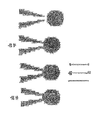
ギガ固着(gigaseal)抵抗を獲得するために界面距離がいかに小さくなくてはならないかは、固着の形状及び脂質膜と固着表面との間の接触面積の拡大によって変化する(図1B参照)。しかしながら、細胞表面の細胞外に付着した分子(例えば、細胞受容体)が存在するとき、全ての固着のために、細胞接触表面又は固着表面は許容される以上に脂質膜により接近されなくてはならない。短い距離において、ファン・デル・ワールス力は非常に強くなり、そこから逃れることが不可能な最小値のエネルギーにて、細胞又はその一部を動かないようにする恐れがある。従って、生物学的に「通常」な状況にて適切な距離を維持するために何かが必要であり、細胞膜の異なる点での糖衣及び局所的な粗さが、ファン・デル・ワールス力が弱くその他の力によってバランスされることが可能である別の細胞との間の界面距離の形成を可能とする。細胞膜を電極区画から分離する表面の開口部と細胞膜との間のギガシールを得るために、これらの細胞膜の距離−保持機構は効果的な方法で妨害されなくてはならない。 How small the interfacial distance must be in order to obtain a gigaseal resistance depends on the shape of the anchor and the enlargement of the contact area between the lipid membrane and the anchoring surface (see FIG. 1B). However, when there are molecules attached extracellularly on the cell surface (eg cell receptors), for all anchoring, the cell contact surface or anchoring surface must be closer to the lipid membrane than allowed. Don't be. At short distances, van der Waals forces become so strong that they can keep a cell or a part of it from moving with the minimum amount of energy that cannot escape. Therefore, something is needed to maintain the proper distance in biologically “normal” situations, and sugar coatings and local roughness at different points of the cell membrane can help van der Waals forces. Allows the formation of an interfacial distance between another cell that is weak and can be balanced by other forces. In order to obtain a giga-seal between the surface opening that separates the cell membrane from the electrode compartment and the cell membrane, these cell membrane distance-retention mechanisms must be disturbed in an effective manner.
(1)電極区画から細胞を分離する表面の形状特性
電極区画から細胞を分離する開口部を規定する突出した表面は、開口部と細胞膜との間の分離距離を極小化し、細胞と開口部の表面との間の接触点にて電気抵抗を増大させるために重要であるということが、本発明の発明事項である。細胞表面に存在する分子の存在が開口部を規定する表面に対する細胞膜の親密な付着を妨害している。これは、細胞画に付着した分子が細胞膜の表面と開口部を規定する表面との間の親密な接触を妨害するスペーサとして作用するので、平面又は陥凹しているかの何れかの表面について特に断言される。一方、開口部を規定する突出した表面については、その他の形状を備えている場合と比較してこれらの分子が非常に容易に移動されるので、細胞外に付着した分子の存在は分離距離の決定についてあまり気にしなくて良い。
(1) Shape characteristics of the surface separating cells from the electrode compartment The protruding surface defining the opening separating cells from the electrode compartment minimizes the separation distance between the opening and the cell membrane, It is an inventive matter of the present invention that it is important to increase the electrical resistance at the point of contact with the surface. The presence of molecules present on the cell surface prevents intimate attachment of the cell membrane to the surface defining the opening. This is especially true for either planar or recessed surfaces, as molecules attached to the cell compartment act as spacers that prevent intimate contact between the surface of the cell membrane and the surface defining the opening. Affirmed. On the other hand, on the protruding surface that defines the opening, these molecules are moved much more easily than when they have other shapes, so the presence of molecules attached to the outside of the cell is the separation distance. Don't worry too much about the decision.
(1)開口部を規定する表面と細胞膜との間の初期接触面が非常に小さく、(2)細胞表面に加えられることが可能な(吸引に夜或いは細胞膜への圧力による)局所的圧迫及び応力が非常に高いので、この移動は開口部を規定する突出した表面にとって起こり得る。相俟って、これらの二つの効果は、細胞膜表面と開口部を規定する突出した表面との間の初期接触領域にて、細胞外に付着した分子の移動を引き起こし、従って、二つの表面の間の分離距離を劇的に減少させる。この導入された圧力は、脂質膜のエントロピー的に促進された変動を抑え、膜表面の凹凸を平らにする膜伸張を増加させる。 (1) the initial contact surface between the surface defining the opening and the cell membrane is very small, and (2) local compression (at night to suction or by pressure on the cell membrane) that can be applied to the cell surface and Because the stress is so high, this movement can occur for the protruding surface that defines the opening. Together, these two effects cause the movement of molecules attached to the outside of the cell at the initial contact region between the cell membrane surface and the protruding surface defining the opening, and thus the two surface Dramatically reduces the separation distance between. This introduced pressure suppresses the entropy-promoted variation of the lipid membrane and increases membrane stretch that flattens the membrane surface irregularities.
図1Bに例示したその他の重要な要因は、細胞と表面との間の固着の質における開口部を規定する表面の形状の効果である。膜の表面と開口部を規定する表面との間の分離距離について、円筒状の内面/外面を備えた開口部を規定する突出した表面は平面のものより高抵抗固着を得ることについて優れている。これは、電流が電極区画から細胞膜へ運搬される電極区画から細胞膜を分離する絶縁表面について例示される。電流の流路を断片に分けることにより、突出した表面のため、電流路に沿った漏れ電流の一定の断面積によって、各々が同等に長い流路断片が各々総固着抵抗と同等に寄与するということを示すことが可能である。 Another important factor illustrated in FIG. 1B is the effect of the shape of the surface defining the opening in the quality of adhesion between the cell and the surface. With respect to the separation distance between the membrane surface and the surface defining the opening, the protruding surface defining the opening with the cylindrical inner / outer surface is superior in obtaining a higher resistance anchor than the planar one. . This is illustrated for an insulating surface that separates the cell membrane from the electrode compartment where current is carried from the electrode compartment to the cell membrane. By dividing the current flow path into pieces, because of the protruding surface, each of the equally long flow path pieces contributes to the total fixed resistance due to the constant cross-sectional area of the leakage current along the current path. It is possible to show that.
一方、開口部からなる平面の表面に対して細胞が固着されるとき、異なる減少が生じる。そのような固着を介して電流が漏れるとき、開口部から放射方向へ漏れる。この場合、開口部からなる平面の表面と細胞との間に形成された固着の放射状の断片の各々からの抵抗の寄与率は断片の半径に反比例する。これは、漏れは電流路に沿って増加し得、その結果電流密度は減少し、形状の非効率性を例示していることを意味する。 On the other hand, a different reduction occurs when cells are attached to a planar surface consisting of openings. When current leaks through such sticking, it leaks radially from the opening. In this case, the resistance contribution from each of the anchoring radial fragments formed between the planar surface of the opening and the cell is inversely proportional to the radius of the fragment. This means that leakage can increase along the current path, resulting in a decrease in current density, illustrating shape inefficiencies.
固着面の抵抗の依存もまた図1A及びB中に提示されるシミュレーションに用いられている方程式中に見られる。 The sticking surface resistance dependence is also seen in the equations used in the simulation presented in FIGS. 1A and B.
平面の形状について、抵抗Rは、
R=1/2πσd・ln(ro/ri)
より算出され、ここにおいてσは電解質の導電性、dは界面の裂溝の寸法、roは固着面の外径、そしてriは固着面の内径(すなわち、開口部の半径)である。
For a planar shape, the resistance R is
R = 1 / 2πσd · ln (r o / r i )
Where σ is the electrolyte conductivity, d is the interface fissure size, r o is the outer diameter of the anchoring surface, and r i is the inner diameter of the anchoring surface (ie, the radius of the opening).
円筒形の形状について、抵抗Rは、
R=α/[r2π−(r−d)2π]σ
より算出され、ここにおいてαはピペットの軸方向の固着の長さ、rはピペット内径、そしてdはピペット内壁/外壁と脂質膜との間の界面距離である。
For cylindrical shapes, the resistance R is
R = α / [r 2 π− (r−d) 2 π] σ
Where α is the length of axial fixation of the pipette, r is the pipette inner diameter, and d is the interfacial distance between the pipette inner / outer wall and the lipid membrane.
シミュレーションにおいて、σは16mS/cmと設定される。 In the simulation, σ is set to 16 mS / cm.
(2)開口部を規定する表面の化学表面特性
図1Aは、電極区画から細胞膜を分離する開口部を規定する表面と細胞膜との間の距離を極小化することの重要性、或いはいくつかの形状を保持しているので、開口部を規定する表面と細胞膜との間の増大した接触表面の重要性を例示する。
(2) Chemical surface characteristics of the surface defining the opening . FIG. 1A shows the importance of minimizing the distance between the surface defining the opening separating the cell membrane from the electrode compartment and the cell membrane, or Since it retains its shape, it illustrates the importance of the increased contact surface between the surface defining the opening and the cell membrane.
従って、ある態様において、本発明は細胞とそのような開口部との間の固着抵抗を極大化する方法を提供し、その結果、パッチクランプ記録の効果を極大化する。経験的に、表面が親水性であるとき、脂質膜とそのような開口部を規定する表面との間の引力相互作用は極大化されることが見出された。表面をより親水性にすると、引力相互作用がより強くなる。強い引力はより大きな接触面積を提供し、二つの表面の間のより短い分離距離を提供し、その結果高固着抵抗をもたらす。 Accordingly, in certain embodiments, the present invention provides a method for maximizing the adhesion resistance between cells and such openings, thereby maximizing the effectiveness of patch clamp recording. Empirically, it has been found that when the surface is hydrophilic, the attractive interaction between the lipid membrane and the surface defining such openings is maximized. The more hydrophilic the surface, the stronger the attractive interaction. A strong attractive force provides a larger contact area and a shorter separation distance between the two surfaces, resulting in a high sticking resistance.
強い引力はより大きな接触面積を供給し、分析された先端及び細胞の間の表面相互作用エネルギーは細胞を変形させるのに十分である。 Strong attraction provides a larger contact area, and the surface interaction energy between the analyzed tip and cell is sufficient to deform the cell.
図3A及びBにおいて、未処理カバースリップと加水分解されたカバースリップとでの脂質小胞の接触面積の違いが示される。多くの場合、強い相互作用はより短い界面距離を反映する。接触表面から脂質膜を遊離するためには更なるエネルギーが必要なので、固着抵抗における好ましい効果に加えて、強い相互作用もまた付着の安定性を増大させる。多数のストラテジーがより高い親水性表面を達成するために実行され得る。ある態様において、ガラス(すなわち、SiO2)表面は、RCA−1洗浄ステップを用いて表面を加水分解することにより、例えば、70−80℃の水、過酸化水素及びアンモニア(H2O:H2O2:NH3 5:1:1)の溶液中に表面を10分間漬け、続いて脱イオン化された水中にてすすぐことにより、或いは表面を火炎−処理することにより、或いは高荷電ポリマーで表面を被覆することにより、その生来の状態と比較してより親水性にされる。 In FIGS. 3A and B, the difference in lipid vesicle contact area between untreated and hydrolyzed coverslips is shown. In many cases, strong interactions reflect shorter interface distances. In addition to the positive effect on anchoring resistance, strong interactions also increase the stability of the attachment, as additional energy is required to release the lipid membrane from the contact surface. A number of strategies can be implemented to achieve a higher hydrophilic surface. In some embodiments, the glass (ie, SiO 2 ) surface is hydrolyzed using an RCA-1 cleaning step, for example, water, hydrogen peroxide and ammonia (H 2 O: H at 70-80 ° C.). 2 O 2 : NH 3 5: 1: 1) soaking the surface for 10 minutes, followed by rinsing in deionized water, or by flame-treating the surface, or with a highly charged polymer Coating the surface makes it more hydrophilic compared to its native state.
(3)高電気抵抗固着の形成における流体流の影響
(例えば、流体を流すことにより生じる)余分な力の追加は、表面に対して細胞膜を最初に固着するときにシステムの力を平衡にシフトする。これは新たなエネルギー最小値を作り出し、本システムがもとのエネルギーの最大値を越えるようにし、新たな最小値をもたらすことが可能である。電極区画から細胞膜を分離する開口部を規定する表面にゆるく付着した細胞膜を制御された速度及び方向性の液体流にさらすことにより、細胞膜は細胞膜と表面との間の固着の抵抗を増大させ安定化することが可能である。
(3) The effect of fluid flow in the formation of a high electrical resistance anchor (eg, caused by flowing fluid) adds extra force to shift the system force to equilibrium when the cell membrane is first anchored to the surface. To do. This creates a new energy minimum, allowing the system to exceed the original energy maximum, resulting in a new minimum. By exposing the loosely attached cell membrane to the surface defining the opening separating the cell membrane from the electrode compartment to a controlled velocity and directional liquid flow, the cell membrane increases and stabilizes the adhesion between the cell membrane and the surface. It is possible to
パッチクランプ細胞における液体流の効果は、細胞における流れによりもたらされた力(ストークス抗力)に起因する。この力は以下の方程式から計算されることが可能である:
F=6πrηv
ここにおいて、Fは力、rは細胞の半径、vは流体の速度そしてηは流体の粘度である。この関係は低レイノルズ数流及び球形粒子に対して有効である。
The effect of fluid flow in patch clamp cells is due to the force (Stokes drag) caused by the flow in the cells. This force can be calculated from the following equation:
F = 6πrηv
Where F is the force, r is the radius of the cell, v is the velocity of the fluid and η is the viscosity of the fluid. This relationship is valid for low Reynolds number flows and spherical particles.
1センチポイズの粘度を備えた水性媒体中の5−μm−半径の球形の細胞を通り過ぎる2mm/sの流速は、結果として〜200pNの力である。相対的に、同じ細胞に作用する沈殿作用の力は〜0.4pNである。 A flow rate of 2 mm / s through a 5-μm-radius spherical cell in an aqueous medium with a viscosity of 1 centipoise results in a force of ˜200 pN. In comparison, the force of precipitation acting on the same cells is ˜0.4 pN.
実施の単純化のため以下の記載では圧力−駆動流を強調したが、マイクロチャネル中の液体を輸送するための多数の適切な手段を設計することが可能であり、電気浸透流、表面伸張駆動流、移動壁駆動流、温度勾配駆動流、超音波誘発流、及び剪断駆動流が挙げられるが、これに限定されない。これらの技術は当技術分野において知られており、そしてまた2002年2月12日に出願された米国仮特許出願公開第60/356,377号公報に記載されており、その全体がここに参照として組み込まれる。 For simplicity of implementation, the following description has emphasized pressure-driven flow, but many suitable means for transporting liquids in microchannels can be designed, electroosmotic flow, surface extension driven Flow, moving wall driven flow, temperature gradient driven flow, ultrasonically induced flow, and shear driven flow. These techniques are known in the art and are also described in US Provisional Patent Application No. 60 / 356,377, filed Feb. 12, 2002, which is hereby incorporated by reference in its entirety. Incorporated as.
パッチクランプを用いた長時間のイオンチャネル活性を記録する能力は、細胞表面相互作用の高電気固着抵抗及び安定性に非常に依存している。ここでは、流体条件の範囲のもとでの「ギガシール」の改良された安定性が記載されている。特に、細胞が非常に長い記録に使用されるとき、考慮の必要がある受容体脱感作のみならず、細胞内システム及び代謝産物の低下によって引き起こされる細胞の生活能力賀寿分に機能を果たさないといった、その他の考慮すべき事柄もある。しかしながら、多くの受容体及びイオンチャネルシステムのために、これらの要因がわずかな役割しか果たさず、パッチクランプ記録は本発明のシステム及び方法を用いて単一細胞に数時間の実施されることが可能である。 The ability to record long-term ion channel activity using patch clamps is highly dependent on the high electroadhesion resistance and stability of cell surface interactions. Here, the improved stability of “Giga Seal” under a range of fluid conditions is described. In particular, when cells are used for very long recordings, they function not only for receptor desensitization that needs to be considered, but also for the vitality of the cells caused by a decline in intracellular systems and metabolites. There are other considerations, such as no. However, for many receptor and ion channel systems, these factors play a minor role and patch clamp recordings can be performed on a single cell for several hours using the system and method of the present invention. Is possible.
表面処理及び開口部の形状の最適化に加えて、以下の結果、真正面からの流体流によって生じた押す力が、開口部を規定する表面に向かって細胞を効果的に押し付け、細胞と表面との間の固着を非常に安定化することを可能とし、細胞の電気特性の測定を(例えば、パッチクランプ記録)増大した高固着抵抗で長時間可能としたことが実証されている。 In addition to the surface treatment and optimization of the shape of the opening, the following results result in the pushing force generated by the fluid flow from directly in front effectively pushing the cell towards the surface defining the opening, It has been demonstrated that it is possible to greatly stabilize the adhesion between the cells and to measure the electrical properties of the cells (eg patch clamp recording) for a long time with increased high adhesion resistance.
パッチクランプ記録装置の効率を増大させるシステム、システム構成要素及び方法
ある態様において、本発明は長時間、例えば約20分以上、望ましくは約1時間以上、約2時間以上、約3時間以上、約4時間以上、又は約5時間以上細胞膜の電気特性の測定を実施するシステム、システム構成要素及び方法を提供する。
Systems, system components and methods for increasing the efficiency of a patch clamp recording device In some embodiments, the present invention provides a long time, for example about 20 minutes or more, desirably about 1 hour or more, about 2 hours or more, about 3 hours or more, about Systems, system components and methods are provided for performing measurements of cell membrane electrical properties for 4 hours or more, or about 5 hours or more.
ある態様において、本発明によるシステムは、一つ以上の電極からなる電極区画、電解質溶液を受け入れ電極を細胞膜へ電気的に連結するための内腔、及び内腔と流体状態で連通する開口部を規定する表面からなる。ある態様において、内腔はパッチクランプマイクロピペットの空洞部分である。別の態様において、内腔は、パッチクランプ配列装置のようなチップ上のパッチクランプ装置中に細胞を受け入れるための細胞チャンバの一部である。望ましくは、細胞膜は電解質溶液との接触を介して電極と電気的に連通する。 In certain embodiments, a system according to the present invention comprises an electrode compartment comprising one or more electrodes, a lumen for receiving an electrolyte solution and electrically connecting the electrode to a cell membrane, and an opening in fluid communication with the lumen. It consists of a defined surface. In certain embodiments, the lumen is a cavity portion of a patch clamp micropipette. In another embodiment, the lumen is part of a cell chamber for receiving cells into a patch clamp device on a chip, such as a patch clamp array device. Desirably, the cell membrane is in electrical communication with the electrode through contact with the electrolyte solution.
ここにおいて使用されるように、電解質溶液を包含する内腔及び電極は「電極区画」を規定する。場合によって、電気素子は電極区画の一部を形成することが可能である。内腔と連通する開口部を規定する表面は電極区画と細胞との間、より望ましくは電極区画と、細胞膜が存在する浴溶液との間の仕切りとしての機能を果たす。 As used herein, the lumen and electrode containing the electrolyte solution define an “electrode compartment”. In some cases, the electrical element can form part of the electrode compartment. The surface defining the opening that communicates with the lumen serves as a partition between the electrode compartment and the cells, more preferably between the electrode compartment and the bath solution in which the cell membrane is present.
好適な表面としては、ガラス(例えば、表面がパッチクランプマイクロピペットの一部であるとき)又は炭素ベースポリマー、シリコンベースポリマー、プラスチック及びそれらの改質又は処理された形態のような、ポリマーが挙げられる。 Suitable surfaces include polymers such as glass (eg when the surface is part of a patch clamp micropipette) or carbon-based polymers, silicon-based polymers, plastics and their modified or treated forms. It is done.
望ましくは、開口部を規定する表面は非平面であり、より望ましくは突出している。開口部を規定する表面がチップ上の装置の隙間(aperture)からなるとき、望ましくは隙間(aperture)での表面トポグラフィーもまた突出しており、その結果開口部は装置を形成する絶縁表面の残余物と異なる平面に存在し、望ましくは少なくとも約1μm−1000μm、そして望ましくは少なくとも約1μm−100μmまで絶縁表面の残余物より高い。一般的に、突出部の寸法は細胞表面に応力を生じさせるのに十分大きいように選択される。 Desirably, the surface defining the opening is non-planar and more desirably protrudes. When the surface defining the opening consists of a device aperture on the chip, preferably the surface topography at the aperture is also protruding, so that the opening is a residual of the insulating surface forming the device. Present in a different plane, preferably at least about 1 μm-1000 μm, and preferably at least about 1 μm-100 μm higher than the remainder of the insulating surface. In general, the dimensions of the protrusions are selected to be large enough to cause stress on the cell surface.
別の方法として又は加えて、表面は、例えば、上記のようなRCA洗浄方法又は火炎処理又は化学処理によって、表面の少なくとも細胞膜含有部分を親水性にするために処理される。 Alternatively or in addition, the surface is treated to render at least the cell membrane-containing portion of the surface hydrophilic, for example by RCA cleaning methods or flame treatment or chemical treatment as described above.
別の方法として又は加えて、開口部での表面特性は、高電気抵抗固着の形成を増強するために改質されて良い。例えば、細胞はリーブ、カラム、ロッド及び表面の突起部のようなナノスケールの構造を配置し、相互作用し、反応することが示されており、そしてこれらの相互作用は細胞運動、位置決め、そして表面へ付着させる能力のために重要であることが実証されている。従って、ナノ構造の表面は、固着工程において重要であるようであり、そして長時間の記録のための安定した固着を提供するようである。ナノ構造は当技術分野において知られた方法を使用して、例えばハード又はソフトリソグラフィ、蒸着又は原子間力顕微鏡検査(AFM)によって、電極区画から細胞を分離するため、表面において生じさせることが可能である。 Alternatively or in addition, the surface properties at the opening may be modified to enhance the formation of high electrical resistance anchoring. For example, cells have been shown to place, interact, and react with nanoscale structures such as leaves, columns, rods and surface protrusions, and these interactions are cell movements, positioning, and It has proven important for its ability to adhere to surfaces. Thus, the surface of the nanostructure appears to be important in the anchoring process and seems to provide stable anchoring for long time recording. Nanostructures can be generated at the surface to separate cells from the electrode compartment using methods known in the art, for example by hard or soft lithography, vapor deposition or atomic force microscopy (AFM) It is.
別の好ましい態様において、パッチクランプ配列装置のようなチップ上の装置中に、細胞チャンバそれ自身の表面トポグラフィーが細胞チャンバの開口部と細胞膜との間の固着を極大化するために設計される。ある態様において、チャンバは、チャンバ内部の細胞の動きを制限し及び/又は開口部を規定する表面に対して細胞を位置決めすることを補助する非平面表面機構からなり、細胞と細胞接触表面との間の固着の電気抵抗を増大させる(例えば、図4及び図6参照)。例えば、ピラミッド型の構造が細胞チャンバの底部にて微細製作されることが可能である。ある態様において、ピラミッド型構造の先端は細胞を受け入れるよう陥凹型である。 In another preferred embodiment, in a device on a chip, such as a patch clamp array device, the surface topography of the cell chamber itself is designed to maximize the adhesion between the cell chamber opening and the cell membrane. . In certain embodiments, the chamber comprises a non-planar surface mechanism that limits cell movement within the chamber and / or assists in positioning the cell relative to the surface defining the opening, and the cell and cell contact surface Increase the electrical resistance of the adhesion between them (see, eg, FIGS. 4 and 6). For example, a pyramidal structure can be microfabricated at the bottom of the cell chamber. In certain embodiments, the tip of the pyramidal structure is recessed to accept cells.
望ましくは、細胞チャンバは比較的浅い。ここで使用されているように、用語「浅い」は細胞がチャンバ内部で自由に動くことをチャンバ内部で拘束され、その結果、細胞がチャンバ内部でその位置を実質的に変化しない、すなわち細胞に電流を配送するために細胞はセンサーの細胞接触表面の直径の約2倍未満しか動かないという事実を指す。この場合における流体流は、細胞と連通するマイクロチャネルの使用を介して提供され得るが、さもなければ電解質溶液からなる細胞チャンバの部分へそれらの内容物を提供しない。一つ以上の流動チャネル及び/又はバルブは細胞膜の迅速な溶液交換(すなわち、潅流)を許容するため本発明の装置中へ組み込まれることが可能である。 Desirably, the cell chamber is relatively shallow. As used herein, the term “shallow” constrains a cell to move freely within the chamber so that the cell does not substantially change its position within the chamber, ie It refers to the fact that in order to deliver current, the cell moves less than about twice the diameter of the cell contact surface of the sensor. Fluid flow in this case can be provided through the use of microchannels in communication with the cells, but otherwise does not provide their contents to the portion of the cell chamber that consists of the electrolyte solution. One or more flow channels and / or valves can be incorporated into the device of the present invention to allow rapid solution exchange (ie, perfusion) of the cell membrane.
パッチクランプ配列装置のようなチップ上の装置において、細胞膜は望ましくは開口部からなる表面に近接して設置される。配列装置の個別のチャンバへの細胞の付加はそれらを分解することにより、例えばnQUAD吸引ディスペンサを使用することにより仲介することができる。電気泳動、吸引、電圧パルスの使用等のような、その他の方法が細胞を位置決めするために使用されることが可能である。 In an on-chip device such as a patch clamp array device, the cell membrane is desirably placed in close proximity to the surface comprising the opening. The addition of cells to the individual chambers of the array device can be mediated by disassembling them, for example by using an nQUAD suction dispenser. Other methods such as electrophoresis, aspiration, use of voltage pulses, etc. can be used to position the cells.
ある態様において、圧力−駆動流は、基板中のマイクロ流体チャネルからチップ上のパッチクランプ装置の適切な細胞チャンバへの細胞の動きを操作するために使用される。細胞の経路指定は、複数のマイクロチャネルからなる基板中のチャネルの分岐をブロックすること、当技術分野において知られているようなバルブを用いること、その結果細胞を大量の溶液流とともに別の選択されたチャネル中へ移動させることによって影響されることが可能である。 In certain embodiments, pressure-driven flow is used to manipulate the movement of cells from the microfluidic channel in the substrate to the appropriate cell chamber of the patch clamp device on the chip. Cell routing blocks the branching of channels in a substrate consisting of multiple microchannels, uses valves as known in the art, so that cells can be selected differently with a large volume of solution flow Can be influenced by moving into the designated channel.
加えて、又は別の方法として、緩衝溶液のようなイオンを含有した流れに二つ以上の電極の間に電圧差又は電荷勾配を印加することにより運動を作り出すために電気浸透を使用することが可能である。中性の(荷電されていない)細胞は流れによって運ばれることが可能である。例えば、米国特許出願公開第20020049389号公報の記載を参照。 In addition, or alternatively, electroosmosis can be used to create motion by applying a voltage difference or charge gradient between two or more electrodes in an ion-containing stream, such as a buffer solution. Is possible. Neutral (uncharged) cells can be carried by the flow. For example, see the description of US Patent Application Publication No. 20020049389.
誘電泳動は、誘電体の動きを作り出すと信じられており、これは正味荷電を有していないが、互いに関してプラス又はマイナスに帯電した領域を有している。細胞の存在において交流の非同時の電界は細胞を電気的に分極させ、その結果誘電泳動力が生じる。粒子及び懸濁媒体の誘電分極に依存して、誘電体粒子は高い電界の強さ又は低い電界の強さの領域のいずれかに向かって移動する。生きている細胞の分極率は細胞の種類に依存し、これは細胞分離のための原理を例えば差動誘電泳動力によって提供し得る。例えば、米国特許出願公開第20020058332号公報の記載を参照。 Dielectrophoresis is believed to create dielectric motion, which has no net charge but has positively or negatively charged regions with respect to each other. In the presence of cells, alternating non-simultaneous electric fields polarize the cells electrically, resulting in dielectrophoretic forces. Depending on the dielectric polarization of the particles and the suspending medium, the dielectric particles move towards either high electric field strength or low electric field strength regions. The polarizability of living cells depends on the cell type, which can provide the principle for cell separation, for example by differential dielectrophoretic forces. For example, see the description of US Patent Application Publication No. 20020058332.
レーザ又は最適な光ピンセットのような光の集束ビームで細胞をゆがめ移動させるために、放射圧もまた使用することが可能である。 Radiation pressure can also be used to distort and move cells with a focused beam of light, such as a laser or optimal optical tweezers.
別の態様において、本システムは2002年2月12日に出願された米国仮特許出願公開第60/356,377号公報に記載のような細胞ベースバイオセンサーの一部であり、その全体がここに参照として組み込まれる。この態様において、細胞、又はその一部は細胞含有容器(receptacle)又は槽(reservoir)内部に設置され、浴溶液にさらされる。細胞含有容器は望ましくは開口容積区画と連通する一つ以上の流体源から流体を受け入れることが可能な底部及び壁面からなる開口容積区画である。バイオセンサーは、細胞、チャンバ又は電極区画を移動させることにより細胞へ近接するようになることが可能な電極区画からなる。細胞チャンバは、流体の流れ、試薬及び/又は細胞それ自体を細胞チャンバへ提供する複数のマイクロチャネルからなるマイクロ流体装置の一部であって良い。上記方法の一つ以上、すなわち、圧力−駆動流、電気浸透、誘電泳動、放射圧(例えば、光ピンセット)等を用いてチャネルから細胞チャンバ中へ一つ以上の細胞を送ることが可能である。 In another aspect, the system is part of a cell-based biosensor as described in US Provisional Patent Application Publication No. 60 / 356,377, filed February 12, 2002, the entirety of which is here Incorporated by reference. In this embodiment, the cells, or portions thereof, are placed inside a cell containing receptacle or reservoir and exposed to a bath solution. The cell-containing container is desirably an open volume compartment consisting of a bottom and a wall capable of receiving fluid from one or more fluid sources in communication with the open volume compartment. A biosensor consists of an electrode compartment that can be brought into close proximity to the cell by moving the cell, chamber or electrode compartment. The cell chamber may be part of a microfluidic device consisting of a plurality of microchannels that provide fluid flow, reagents and / or cells themselves to the cell chamber. One or more of the above methods can be used to deliver one or more cells from the channel into the cell chamber using pressure-driven flow, electroosmosis, dielectrophoresis, radiation pressure (eg, optical tweezers), etc. .
細胞チャンバの精密な形状は、パッチクランプマイクロピペットのような少なくとも一つの電極区画に近接する一つの細胞又はその一部、複数の細胞又はその一部を保持することが可能である限り、限定されない。この態様において、チャンバは典型的には無傷な細胞と生理的に混合可能な浴溶液を包含する。少なくとも一つの電極区画(例えば、マイクロピペット)は電極区画内部の電極と細胞膜との間の好適な電気的連通を維持するための電解質溶液を包含する。電極区画中の一つ以上の電極に細胞を電気的に連結する電極溶液が流れることが可能な開口部を規定する表面によって、細胞は電極区画から分離される。 The precise shape of the cell chamber is not limited as long as it is possible to hold one cell or part thereof, a plurality of cells or part thereof proximate to at least one electrode compartment, such as a patch clamp micropipette. . In this embodiment, the chamber typically contains a bath solution that is physiologically compatible with intact cells. At least one electrode compartment (eg, a micropipette) includes an electrolyte solution for maintaining suitable electrical communication between the electrode inside the electrode compartment and the cell membrane. Cells are separated from the electrode compartment by a surface that defines an opening through which an electrode solution that electrically connects the cells to one or more electrodes in the electrode compartment can flow.
細胞は流体流を用いて電極区画に近接するよう移動させることが可能である。開口容積チャンバ中の一つ以上の流体の流れは、米国仮特許出願公開第60/356,377号公報に記載されているような開口容積チャンバ中へ供給するマイクロチャネルの使用を介して生じさせられ得、細胞上に押す力を提供するために使用されることが可能である。別の方法として又は加えて、光ピンセットを用いて又は電極区画それ自身を移動させることにより(例えば、電極区画がパッチクランプマイクロピペットからなるときのような微細位置決め装置の使用を介して)細胞を移動することが可能である。細胞チャンバそれ自身は、例えば細胞チャンバ内部の電気浸透流を生じさせるか、電極区画に向かうその動きを促進するために細胞を分極する適切な電極区画に近接するよう細胞を位置決めすることを援助するための電界を生じさせるために一つ以上の電気素子を含むよう形状が定められることが可能である。 Cells can be moved closer to the electrode compartment using fluid flow. The flow of one or more fluids in the open volume chamber is generated through the use of a microchannel that feeds into the open volume chamber as described in US Provisional Patent Application Publication No. 60 / 356,377. Can be used and used to provide a pushing force on the cell. Alternatively or in addition, cells can be removed using optical tweezers or by moving the electrode compartment itself (eg, through the use of a micropositioning device such as when the electrode compartment consists of a patch clamp micropipette) It is possible to move. The cell chamber itself assists in positioning the cell in close proximity to the appropriate electrode compartment, for example to create an electroosmotic flow inside the cell chamber or to polarize the cell to facilitate its movement towards the electrode compartment The shape can be defined to include one or more electrical elements to generate an electric field for the purpose.
流体流はまた、電極区画から細胞を分離する開口部を規定する表面と細胞膜との間の固着の電気抵抗を増大させるために使用されることが可能である。例えば、表面の開口部にゆるく付着した細胞は液体の流れを提供する流体流源の出口に近接して設置されることが可能である。細胞は流れにさらされているものの、開口部を規定する表面と接する細胞膜の面積が劇的に増大し、安定な固定が生じる(例えば、実施例3及び図参照)。 The fluid flow can also be used to increase the electrical resistance of adhesion between the surface defining the opening separating the cells from the electrode compartment and the cell membrane. For example, cells loosely attached to a surface opening can be placed in close proximity to the outlet of a fluid flow source that provides a flow of liquid. Although the cells are exposed to flow, the area of the cell membrane in contact with the surface defining the opening increases dramatically, resulting in stable fixation (see, eg, Example 3 and Figure).
従って、ある態様において、細胞膜は流れからの圧力を受ける流体の流れに十分に近接して設置される。この圧力は電極区画から細胞膜を分離する表面の開口部と、細胞膜との間の固着の形成を容易にし、或いは固着を増強させる。流体の流れは、上記のような細胞ベースバイオセンサー中の開口容積チャンバのような細胞を包含するチャンバへ供給され得る。チップ上のパッチクランプ装置において、流体の流れは、当技術分野においてありきたりな方法を用いて装置中に微細製作されたマイクロ流体チャネルを通過して細胞へ供給され得る。 Thus, in some embodiments, the cell membrane is placed sufficiently close to the fluid flow that is subject to pressure from the flow. This pressure facilitates or enhances adhesion between the cell membrane and the opening in the surface that separates the cell membrane from the electrode compartment. The fluid flow can be supplied to a chamber containing cells, such as an open volume chamber in a cell-based biosensor as described above. In a patch clamp device on a chip, fluid flow can be delivered to cells through microfabricated channels microfabricated in the device using routine methods in the art.
望ましくは、流体流源は0.01mm/s乃至100cm/s、望ましくは0.1mm/s乃至10cm/sの範囲の流速で液体の流れを提供する。 Desirably, the fluid flow source provides a liquid flow at a flow rate in the range of 0.01 mm / s to 100 cm / s, preferably 0.1 mm / s to 10 cm / s.
従って、ある態様において、本発明は、一つ以上の細胞を含むチャンバ又は槽に入る少なくとも一つの出口からなる流体流源を有する細胞ベースバイオセンサーを提供する。流体流源は、一つ以上の細胞へ流体の流れを提供することが可能な少なくとも一つのマイクロチャネルからなっていることが可能である(例えば、図2A及びB、及び図10A及びBを参照)。別の態様において、流体流源は、一つ以上の細胞の位置をマイクロピペットの先端に対して位置決めし及び/又は維持するための複数の流体の流れを提供するため複数の出口からなる。複数の出口は、例えばマイクロチャネルを基板上に積み重ねた状態のように単一平面又は多数の平面に存在させて良い(図示せず)。多数の流体流源は、異なる方向、すなわち、例えば互いに垂直のように流れる流体の流れを提供する単一基板の一部として提供されることが可能であり(例えば、図11A及びB参照)、細胞接触表面の面に対して斜めに細胞を動かすことが可能である。流体流源の更なる構造は2002年2月12日に出願された米国仮特許出願第60/356,377号に記載されており、その全体がここに参照として組み込まれる。 Accordingly, in certain embodiments, the present invention provides a cell-based biosensor having a fluid flow source consisting of at least one outlet that enters a chamber or bath containing one or more cells. The fluid flow source can consist of at least one microchannel capable of providing fluid flow to one or more cells (see, eg, FIGS. 2A and B and FIGS. 10A and B). ). In another aspect, the fluid flow source comprises a plurality of outlets to provide a plurality of fluid flows for positioning and / or maintaining the position of one or more cells relative to the tip of the micropipette. The plurality of outlets may be present in a single plane or multiple planes (not shown), such as, for example, stacked microchannels on a substrate. Multiple fluid flow sources can be provided as part of a single substrate that provides fluid flows that flow in different directions, eg, perpendicular to each other (see, eg, FIGS. 11A and B); It is possible to move the cells obliquely with respect to the surface of the cell contact surface. Additional structures for fluid flow sources are described in US Provisional Patent Application No. 60 / 356,377, filed February 12, 2002, which is hereby incorporated by reference in its entirety.
高電気抵抗固着を形成するための上記方法に加えて、固着の電気抵抗を増強するために細胞を電極区画から分離する表面の開口部に吸引を加えることが可能である。別の方法として又は加えて、一つ以上の電圧パルスを開口部に印加して固着の電気抵抗を増強させる(例えば、マイクロピペットの内部電極或いはパッチクランプ配列の一つ以上の電極を用いる)。 In addition to the above method for forming a high electrical resistance anchor, it is possible to apply suction to a surface opening that separates the cells from the electrode compartment to enhance the electrical resistance of the anchor. Alternatively or additionally, one or more voltage pulses are applied to the aperture to increase the electrical resistance of the anchor (eg, using an internal electrode of a micropipette or one or more electrodes of a patch clamp array).
上記の一連は、例えば図7に図示される。 The above series is illustrated in FIG. 7, for example.
別の方法として、一連の出来事は以下のとおりであって良い:
電極区画から細胞膜を分離するための開口部からなる表面は、細胞膜を移動させるか、表面を移動させるか或いは細胞膜と表面との両者を移動させることの何れかによって細胞膜に隣接して位置決めされる。わずかな吸引及び/又はいくつかの電圧パルスが開口部に加えられる。
Alternatively, the sequence of events may be as follows:
The surface comprising the opening for separating the cell membrane from the electrode compartment is positioned adjacent to the cell membrane by either moving the cell membrane, moving the surface, or moving both the cell membrane and the surface. . A slight suction and / or several voltage pulses are applied to the opening.
表面にゆるく保持された細胞膜(例えば、表面から0.01μm未満)は液体の流れを提供する流体流源の出口へ近接して設置される。細胞膜は流体の流れにさらされているものの、表面と接する膜の表面積が劇的に増大し、安定な固定が生じる。所定の時間の後、又は思い通りの抵抗の電気測定値に到達したとき、細胞は流体の流れから外れ、すぐに、好適な記録の構成に到達するまで更なる吸引又は更なる電圧が表面に加えられる、すなわち多数の連続的な測定値を著しく越えて変化しない。 A cell membrane loosely held on the surface (eg, less than 0.01 μm from the surface) is placed in close proximity to the outlet of the fluid flow source that provides liquid flow. Although the cell membrane is exposed to fluid flow, the surface area of the membrane in contact with the surface increases dramatically, resulting in stable fixation. After a predetermined time, or when the desired electrical measurement of resistance is reached, the cell is removed from the fluid flow and immediately, additional suction or additional voltage is applied to the surface until a suitable recording configuration is reached. That is, it does not change significantly beyond a number of consecutive measurements.
上記の一連は図8に図示される。 The above sequence is illustrated in FIG.
別の方法として、一連の出来事は以下のとおりであって良い。電極区画から細胞を分離するための表面は細胞に隣接して位置決めされ、及び/又は細胞は表面に隣接して位置決めされる。吸引が表面に加えられ、及び/又は、好適な細胞記録の構造に到達するまで、ひとつ以上の電圧パルスが表面に加えられる。ある望ましい態様において、細胞接触表面に保持された細胞は、所望の電気抵抗が得られるまで液体の流れに近接して設置される。この一連は図9に示される。 Alternatively, the sequence of events may be as follows: The surface for separating cells from the electrode compartment is positioned adjacent to the cells and / or the cells are positioned adjacent to the surface. One or more voltage pulses are applied to the surface until suction is applied to the surface and / or a suitable cellular recording structure is reached. In certain desirable embodiments, the cells held on the cell contact surface are placed in close proximity to the liquid flow until the desired electrical resistance is obtained. This series is shown in FIG.
図6は、細胞がパッチクランプ配列装置中の電極区画から細胞を分離するための開口部を規定する突出した表面へ導かれる実施の形態の例を示している。絶縁表面の一般的に平面部分に対して垂直な流体の流れが細胞上に押す力を及ぼすために提供される。装置が多数の電極区画からなるとき、ベース表面に対して90°以上又は未満の角度にて(図10)又はこの平面に対して垂直に(図11)流れの中の細胞を移動させることによりそのような区画に対し細胞は更に複数の開口部に自動的に位置決めされることが可能である。吸引圧力及び/又は電圧も開口部に加えられ、その結果細胞は各々の電極区画の開口部へ引き付けられ、或いは引っ張られる。別の方法として、誘電泳動を当技術分野において知られているように使用することが可能であり、上記のようなその他の交流(ac)方法も使用することが可能である。 FIG. 6 illustrates an example embodiment in which cells are directed to a protruding surface that defines an opening for separating cells from an electrode compartment in a patch clamp array device. A flow of fluid perpendicular to the generally planar portion of the insulating surface is provided to exert a pushing force on the cell. When the device consists of multiple electrode compartments, by moving the cells in the flow at an angle of 90 ° or more relative to the base surface (FIG. 10) or perpendicular to this plane (FIG. 11) For such compartments, the cells can further be automatically positioned in a plurality of openings. A suction pressure and / or voltage is also applied to the openings so that the cells are attracted or pulled to the openings of each electrode compartment. Alternatively, dielectrophoresis can be used as is known in the art, and other alternating current (ac) methods as described above can also be used.
上記のシステムは、一般的に一つ以上の細胞膜の電気特性を測定することからなる如何なる方法においても使用されることが可能である。本方法において用いるその好適な細胞又は蛋白質としては、細菌、酵母菌、昆虫及び細胞が挙げられるがこれに限定されない。例えば、バチルスspp.、大腸菌、ストレプトコッカスspp.、ストレプトマイセスspp.、シュードモナスspp.を使用することが可能である。その他の低級真核生物と同様に、Saccharomyces cerevisiae, Candida albicans, Candida maltosa, Hansenulapolymorpha, Kluyveromyces fragilis, Kluyveromyces lactis, Pichia guillerimondii, Pichia pastoris, Schizosaccharomyces pombe 及び Yarrowia lipolytic のような酵母細胞も使用されることが可能である。 The above system can be used in any method that generally consists of measuring the electrical properties of one or more cell membranes. Suitable cells or proteins used in the method include, but are not limited to, bacteria, yeast, insects and cells. For example, Bacillus spp. Escherichia coli, Streptococcus spp. Streptomyces spp. Pseudomonas spp. Can be used. Like other lower eukaryotes, yeasts such as Saccharomyces cerevisiae, Candida albicans, Candida maltosa, Hansenulapolymorpha, Kluyveromyces fragilis, Kluyveromyces lactis, Pichia guillerimondii, Pichia pastoris, Schizosaccharomyces pombe lytic can be used. It is.
Aedes aegypti, Autographa californica, Bombyx mori, Drosophila melanogaster, Spodoptera frugiperda, 及び Trichoplusia ni といった昆虫細胞株も使用され得るが、これに限定されない。 Insect cell lines such as, but not limited to, Aedes aegypti, Autographa californica, Bombyx mori, Drosophila melanogaster, Spodoptera frugiperda, and Trichoplusia ni can also be used.
哺乳類細胞株としては、チャイニーズハムスター卵巣(CHO)細胞、ヒーラ細胞、新生児ハムスター腎臓(BHK)細胞、サル腎臓細胞(COS)、ヒト肝細胞癌細胞(例えば、Hep G2)、マディン−ダービーウシ腎臓(MDBK)細胞NIH/3T3,293細胞(ATCC#CRL 1573),COS−7,293,BHK,CHO,TM4,CV1,VERO−76,HELA,MDCK,BRL3A,W138,Hep G2,MMT060562,TRI細胞及びその他のもののようなアメリカン・タイプ・カルチャー・コレクション(ATCC)から入手可能な不死化細胞株が挙げられるが、これに限定されない。鳥細胞株の既知の実施例は、ニワトリB細胞株「DT−40」である。 Mammalian cell lines include Chinese hamster ovary (CHO) cells, HeLa cells, newborn hamster kidney (BHK) cells, monkey kidney cells (COS), human hepatocellular carcinoma cells (eg, Hep G2), Madin-Derby cow kidney ( MDBK) cells NIH / 3T3, 293 cells (ATCC # CRL 1573), COS-7, 293, BHK, CHO, TM4, CV1, VERO-76, HELA, MDCK, BRL3A, W138, Hep G2, MMT060562, TRI cells and Immortalized cell lines available from American Type Culture Collection (ATCC) such as, but not limited to, others. A known example of an avian cell line is the chicken B cell line “DT-40”.
特定の動物細胞としては、白血病L1210細胞(現代薬理学,pp.1121−1129(1978));モルモット心臓細胞(生理学会誌397:237−258(1988);ヒトデ卵細胞(一般生理学会誌70:269−281(1977))及び除神経されたカエル筋繊維(ネエル等、ネイチャー260(1976年4月29日)が挙げられるが、これに限定されない。 Specific animal cells include leukemia L1210 cells (modern pharmacology, pp. 1121-1129 (1978)); guinea pig heart cells (Physiological Society 397: 237-258 (1988); starfish egg cells (General Physiological Society 70: 269-). 281 (1977)) and denervated frog muscle fibers (Neel et al., Nature 260 (Apr. 29, 1976)), but are not limited thereto.
本発明のシステム及び方法を使用して分析された細胞としては、組み換え遺伝子生成物を発現するようにトランスフェクトされた細胞が挙げられる。例えば、細胞は適切なcDNAを有するそのような細胞をトランスフェクトすることによって特定のイオンチャネルを発現するよう設計されることが可能である(例えば、米国特許第5,670,335号明細書を参照)。 Cells analyzed using the systems and methods of the present invention include cells that have been transfected to express a recombinant gene product. For example, cells can be designed to express specific ion channels by transfecting such cells with the appropriate cDNA (see, eg, US Pat. No. 5,670,335). reference).
上述のように、人工細胞又は小胞もまた、そのような細胞の膜中へ挿入された組み換え技術によって作られた蛋白質の有り無しにかかわらず、使用されることが可能である。例えば、米国特許第5,795,782号明細書及び米国特許第6,022,720号明細書を参照。 As mentioned above, artificial cells or vesicles can also be used with or without proteins made by recombinant techniques inserted into the membrane of such cells. See, for example, US Pat. No. 5,795,782 and US Pat. No. 6,022,720.
従って、ある態様において、細胞膜を電極区画から分離する開口部を規定する表面からなるシステムが提供され、細胞膜は開口部に十分に近接するよう設置され、細胞膜と表面との間で高電気抵抗固着(例えば、少なくとも約1Gオームの抵抗)が形成される条件にさらされる。ある態様において、開口部を規定する表面は非平面であり、望ましくは突出している。もう一つの方法として、又は追加の方法として、表面は親水性である。ある態様において、流体流は開口部を規定する表面に近接して形成する固着にて細胞膜を位置決めするために使用される。もう一つの方法として、又は追加の方法として、流体流は既に形成された固着の電気抵抗を極大化するために使用される。望ましくは、細胞膜を横切る電圧又は電流のような細胞膜の電気特性の測定値の少なくとも一つが得られる。より望ましくは、細胞を取り囲んでいる浴溶液中の条件及び/又は剤に細胞が応答した後又は細胞が応答するときに電気特性が測定される。 Accordingly, in one aspect, a system is provided that comprises a surface that defines an opening that separates a cell membrane from an electrode compartment, the cell membrane being placed sufficiently close to the opening, and a high electrical resistance anchor between the cell membrane and the surface. (E.g., a resistance of at least about 1 Gohm) is exposed to conditions under which In certain embodiments, the surface defining the opening is non-planar and desirably protrudes. Alternatively or additionally, the surface is hydrophilic. In certain embodiments, the fluid stream is used to position the cell membrane with a bond formed proximate to the surface defining the opening. Alternatively, or in addition, the fluid flow is used to maximize the electrical resistance of the already formed bond. Desirably, at least one measurement of an electrical property of the cell membrane, such as a voltage or current across the cell membrane, is obtained. More desirably, the electrical properties are measured after or when the cells respond to the conditions and / or agents in the bath solution surrounding the cells.
剤の例としては、蛋白質、DNA、RNA、PNA、受容体作用薬、受容体拮抗薬、神経伝達物質、神経伝達物質類似体、酵素阻害剤、イオンチャネルモジュレータ、G−蛋白質共役型受容体モジュレータ、輸送阻害剤、ホルモン、ペプチド、毒素、抗体、製薬剤、化学物質、プリン作動薬、コリン作動薬、セロトニン作動薬、ドーパミン作動薬、麻酔薬、ベンゾジアゼピン、バルビタール酸塩、ステロイド、アルコール、金属カチオン、カンナビノイド、コレシストキニン、サイトカイン、興奮性アミノ酸、GABA作動薬、ガングリオシド、ヒスタミン作動薬、メラトニン、神経ペプチド、神経毒、エンドセリン、NO化合物、オピオイド、シグマ受容体リガンド、ソマトスタチン、タキキニン、アンギオテンシン、ボンベシン、ブラジキニン、プロスタグランジン及びこれらの剤の組合せが挙げられるが、これに限定されない。 Examples of agents include proteins, DNA, RNA, PNA, receptor agonists, receptor antagonists, neurotransmitters, neurotransmitter analogs, enzyme inhibitors, ion channel modulators, G-protein coupled receptor modulators Transport inhibitors, hormones, peptides, toxins, antibodies, pharmaceuticals, chemicals, purinergic drugs, cholinergic drugs, serotonin agonists, dopamine agonists, anesthetics, benzodiazepines, barbitalates, steroids, alcohols, metal cations , Cannabinoid, cholecystokinin, cytokine, excitatory amino acid, GABA agonist, ganglioside, histamine agonist, melatonin, neuropeptide, neurotoxin, NO compound, opioid, sigma receptor ligand, somatostatin, tachykinin, angiotensin, bombesin , Brazi Nin, prostaglandins and combinations of these agents include, but are not limited thereto.
イオンチャネル又は輸送蛋白質をエンコードする遺伝子の検討は、被検遺伝子による細胞の平行トランスフェクションによって、続いてここに記載されているようなイオン電流のスクリーニングによって、実行されることが可能である。 Examination of genes encoding ion channels or transport proteins can be performed by parallel transfection of cells with a test gene, followed by screening of ionic currents as described herein.
ここに記載されるシステムはまた、化合物の薬理学的特性を特徴付け、そして用量反応データを得る化合物ライブラリのスクリーニングに有効であり得る。 The systems described herein can also be useful for screening compound libraries that characterize the pharmacological properties of compounds and obtain dose response data.
本発明の器具及び方法のために使用され得る剤の例としては、薬物、受容体作用薬、受容体拮抗薬、神経伝達物質、神経伝達物質類似体、酵素阻害剤、イオンチャネルモジュレータ、G−蛋白質共役型受容体モジュレータ、輸送阻害剤、ホルモン、ペプチド、毒素、抗体、製薬剤、化学物質及びこれらの剤の組合せが挙げられる。 Examples of agents that can be used for the devices and methods of the present invention include drugs, receptor agonists, receptor antagonists, neurotransmitters, neurotransmitter analogs, enzyme inhibitors, ion channel modulators, G- Examples include protein-coupled receptor modulators, transport inhibitors, hormones, peptides, toxins, antibodies, pharmaceuticals, chemical substances, and combinations of these agents.
本発明のシステム及び方法のために使用し得る特定の剤としては、プリン作動薬、コリン作動薬、セロトニン作動薬、ドーパミン作動薬、麻酔薬、ベンゾジアゼピン、バルビタール酸塩、ステロイド、アルコール、金属カチオン、カンナビノイド、コレシストキニン、サイトカイン、興奮性アミノ酸、GABA作動薬、ガングリオシド、ヒスタミン作動薬、メラトニン、神経ペプチド、神経毒、エンドセリン、NO化合物、オピオイド、シグマ受容体リガンド、ソマトスタチン、タキキニン、アンギオテンシン、ボンベシン、ブラジキニン、プロスタグランジン及びこれらの剤の組合せが挙げられる。 Specific agents that can be used for the systems and methods of the invention include purine agonists, cholinergic agents, serotonin agonists, dopamine agonists, anesthetics, benzodiazepines, barbitalates, steroids, alcohols, metal cations, Cannabinoid, cholecystokinin, cytokine, excitatory amino acid, GABA agonist, ganglioside, histamine agonist, melatonin, neuropeptide, neurotoxin, endothelin, NO compound, opioid, sigma receptor ligand, somatostatin, tachykinin, angiotensin, bombesin, Examples include bradykinin, prostaglandins, and combinations of these agents.
本発明は、ここに以下の実施例に関して更に例示される。当然のことながら以下のものは実施例のためでしかなく、細部に対する変更は本発明の範囲内に入る場合常になされ得る。 The invention will now be further illustrated with reference to the following examples. It will be appreciated that the following are only for the purpose of example, and changes to the details can be made whenever it falls within the scope of the invention.
実施例1 パッチクランプマイクロピペットの形状を模倣するチップベース突出構造の製作
多くの方法はパッチクランプ測定を実施するために好適な形状を有する突出した細胞接触表面を微細製作するために存在する。ここには、ある特定の手段が記載されており、これによって細胞チャンバ中のピラミッド型の構造の先端にて円形の開口部が微細製作される。
Example 1 Fabrication of a chip-based protruding structure that mimics the shape of a patch clamp micropipette Many methods exist for microfabrication of protruding cell contact surfaces having a suitable shape for performing patch clamp measurements. Here, a specific means is described, whereby a circular opening is microfabricated at the tip of a pyramidal structure in the cell chamber.
フォトリソグラフィのためのマスクをJEOL JBX−5DII電子ビームリソグラフィシステム(中反射(medium reflective)4”クロムマスク及びシプリーUV5レジスト、50keV acc.電圧、線量15μC/cm−2、露光電流5nA)で書き込む標準e−ビームを使用して作製した。レジストを2000rpmにて60秒スピンコートし、250nmのレジストを生じさせ、露光前に熱板上にて130℃で10分間弱焼付けした。パターンを130℃のオーブンにて20分間後露光焼付けし、シプリーMF24−A中にて60秒現像し、DI水中にてすすぎ、そして反応性イオンエッチャー(etcher)中にて灰色にした(プラズマサーム(Plasmatherm)RIE m−95,30s,50W,250mトル,10ccm O2)。クロムを1−2分間バルザーズクロムエッチ#4(Balzers chrome etch#4)中にてエッチングした。シプリー1165リムーバを用いてマスクの残ったレジストを剥ぎ取り、アセトン、イソプロパノール及びDI水にてすすいだ。700nmの熱成長二酸化ケイ素で二面磨き上げられ全厚さ380μmのA3”、[100]、低N−ドープシリコンウェハを反応性イオンエッチャー(プラズマサーム(Plasmatherm)RIE m−95(30s,50W,250mトル,10ccm O2)中にて洗浄し、シプリーS−1813フォトレジストで4000rpmにてスピンコートし、1.3μmのレジストを生じさせ、そしてCarl Suess MA6マスクアライナー上を400nmの波長にて110mJ/cm−2の線量で露光した。パターンNo.1のユニット細胞は450−550μm2で構成されており、ウェハの質及び厚さが二乗の寸法で測定された(例えば、図4A参照)。 Standard for writing masks for photolithography with JEOL JBX-5DII electron beam lithography system (medium reflective 4 "chrome mask and Shipley UV5 resist, 50 keV acc. Voltage, dose 15 μC / cm -2 , exposure current 5 nA) The resist was spin-coated at 2000 rpm for 60 seconds to produce a 250 nm resist and weakly baked on a hot plate for 10 minutes at 130 ° C. before exposure. Post-exposure bake in oven for 20 minutes, developed in Shipley MF24-A for 60 seconds, rinsed in DI water, and grayed out in reactive ion etcher (Plasmatherm RIE m -95, 30s, 50 , 250 meters torr, 10 ccm O 2). Chromium was etched C. in 1-2 minutes Balzers's chrome etch # 4 (Balzers chrome etch # 4 ). Shipley 1165 remover using stripping the remaining resist of the mask, acetone Rinse with isopropanol and DI water.A3 ", [100], low N-doped silicon wafers, polished to two sides with 700 nm thermally grown silicon dioxide and with a total thickness of 380 μm, are made into reactive ion etchers (Plasmatherm). ) Wash in RIE m-95 (30 s, 50 W, 250 mTorr, 10 ccm O 2 ), spin coat with Shipley S-1813 photoresist at 4000 rpm to yield 1.3 μm resist, and Carl Suess MA6 Mask aligner The top was exposed with a dose of 110 mJ / cm −2 at a wavelength of 400 nm, the pattern No. 1 unit cell was composed of 450-550 μm 2 , and the wafer quality and thickness were measured in square dimensions. (See, for example, FIG. 4A).
ウェハをシプリーMF319中にて45秒間現像し、DI水中にてすすぎ、そして反応性イオンエッチャー(etcher)(プラズマサーム(Plasmatherm)RIE m−95,30s,50W,250mトル,10ccm O2)中にて灰色にした(ashed)。ウェハを最終的に10分間130℃にて強焼きした。ウェハの反対側を同じ方法によってS−1813レジストでコートし、10分間130℃にて迅速に強焼きした。二酸化ケイ素をシオテック(SioTech)緩衝化酸化エッチングで12−14分エッチングし、DI水中にてすすいだ。ウェハの残ったレジストをアセトンで剥ぎ取り、イソプロパノール及びDI水中にてすすいだ(図4B)。ウェハを異方性エッチング液(25%テトラメチルアンモニウム水酸化物の水性溶液)の浴中へ漬け、おおよそ9.5時間90℃にてエッチングした(図4C)。エッチング比率は典型的には0.65μm×分−1であり、異方性は40:1であった。ウェハの残った二酸化ケイ素を剥ぎ取り、RCA−1(NH3:H2O2:H2Oの75℃での1:1:5混合物)に10分間漬け、2%のHFに10分間漬け、そしてRCA−2(HCl:H2O2:H2Oの80℃での1:1:5混合物)に10分間漬けた。 Wafers were developed in Shipley MF319 for 45 seconds, rinsed in DI water, and in a reactive ion etcher (Plasmatherm RIE m-95, 30 s, 50 W, 250 mTorr, 10 ccm O 2 ). Ashed. The wafer was finally baked at 130 ° C. for 10 minutes. The opposite side of the wafer was coated with S-1813 resist by the same method and baked rapidly at 130 ° C. for 10 minutes. Silicon dioxide was etched with a SioTech buffered oxidation etch for 12-14 minutes and rinsed in DI water. The remaining resist on the wafer was stripped with acetone and rinsed in isopropanol and DI water (FIG. 4B). The wafer was immersed in a bath of anisotropic etchant (25% tetramethylammonium hydroxide aqueous solution) and etched for approximately 9.5 hours at 90 ° C. (FIG. 4C). The etching ratio was typically 0.65 μm × min− 1 and the anisotropy was 40: 1. The remaining silicon dioxide on the wafer is stripped off and soaked in RCA-1 (NH 3 : H 2 O 2 : H 2 O 1: 1: 5 mixture at 75 ° C.) for 10 minutes and soaked in 2% HF for 10 minutes. And soaked in RCA-2 (a 1: 1: 5 mixture of HCl: H 2 O 2 : H 2 O at 80 ° C.) for 10 minutes.
ウェハを、すすぎ及び乾燥を組み合わせて最終的にDI水ですすいだ。ウェハを1050℃にて25分間熱的に酸化し、約300nmの二酸化ケイ素を産出させた(図4E)。ウェハのパターン化されていない側をシプリーS−1813フォトレジストで4000rpmにてスピンコートし、1.3μmのレジストを生じさせ、マスクNo.2(パターンNo.2のユニット細胞は1μmの円と一致する)を介してCarl Suess MA6マスクアライナー上を400nmの波長にて110mJ/cm−2の線量で露光した。ウェハをシプリーMF319中にて45秒間現像し、DI水中にてすすぎ、そして反応性イオンエッチャー(etcher)(プラズマサーム(Plasmatherm)RIE m−95,30s,50W,250mトル,10ccm O2)中にて灰色にした(ashed)(図4F)。二酸化ケイ素を同様のシステム(プラズマサーム(Plasmatherm)RIE m−95,15分,100W,100mトル,32ccm CF4、8ccmH2、1ccmO2)でエッチングした(図4G)。露光されたシリコンを、STS多重深部反応性イオンエッチャー(etcher)中にて、SF6をエッチングガスとして、C4F8を不活性化ガスとして使用して、800WのRF電力(RF power)、一定のAPC角度の68%にて操作してエッチングし、エッチング時間は0.5秒の超過時間を含み7秒であり、不活性化時間は1秒の超過時間を含み4秒であった。パターンを、シリコン中に埋もれたピラミッド型の二酸化ケイ素構造に到るまでエッチングした(図4G)。隙間(aperture)の底部の露光された二酸化ケイ素を、ピラミッド型の構造の上端中に隙間(aperture)を生成する反応性イオンエッチャー(プラズマサーム(Plasmatherm)RIE m−95,30分,100W,100mトル,32ccm CF4、8ccmH2、1ccmO2)にてエッチングした(図4H)。 The wafer was finally rinsed with DI water combined with rinsing and drying. The wafer was thermally oxidized at 1050 ° C. for 25 minutes to yield about 300 nm of silicon dioxide (FIG. 4E). The unpatterned side of the wafer was spin coated with Shipley S-1813 photoresist at 4000 rpm to yield a 1.3 μm resist. 2 (pattern cell No. 2 unit cells coincide with a 1 μm circle) was exposed on a Carl Suses MA6 mask aligner at a wavelength of 400 nm at a dose of 110 mJ / cm −2 . Wafers were developed in Shipley MF319 for 45 seconds, rinsed in DI water, and in a reactive ion etcher (Plasmatherm RIE m-95, 30 s, 50 W, 250 mTorr, 10 ccm O 2 ). Ashed (FIG. 4F). Silicon dioxide was etched with a similar system (Plasmatherm RIE m-95, 15 min, 100 W, 100 mTorr, 32 ccm CF 4 , 8 ccm H 2 , 1 ccm O 2 ) (FIG. 4G). The exposed silicon is 800 W RF power (RF power) in an STS multiple deep reactive ion etcher using SF 6 as an etching gas and C 4 F 8 as an inert gas, Etching was performed at 68% of a constant APC angle, the etching time was 7 seconds including an overtime of 0.5 seconds, and the inactivation time was 4 seconds including an overtime of 1 second. The pattern was etched until it reached a pyramidal silicon dioxide structure buried in silicon (FIG. 4G). Reactive ion etcher (Plasmatherm RIE m-95, 30 min, 100 W, 100 m) that produces exposed silicon dioxide at the bottom of the aperture and creates an aperture in the top of the pyramidal structure. Torr, 32 ccm CF 4 , 8 ccm H 2 , 1 ccm O 2 ) (FIG. 4H).
ウェハを、今回はマスクNo.3(パターンNo.3のユニット細胞は50μmの円と一致する)を介してCarl Suess MA6マスクアライナー上を400nmの波長にて110mJ/cm−2の線量でもう一度露光した。ウェハをシプリーMF319中にて45秒間現像し、DI水に中てすすぎ、そして反応性イオンエッチャー(etcher)(プラズマサーム(Plasmatherm)RIE m−95,30s,50W,250mトル,10ccmO2)中にて灰色にした(ashed)(図4I)。二酸化ケイ素を同じシステムでエッチングした(プラズマサーム(Plasmatherm)RIE m−95,15分、100W,100mトル,32ccmCF4、8ccmH2,1ccmO2)。構造を最終的に、STS多重深部反応性イオンエッチャー(etcher)中にて、その周囲のシリコンをエッチングすることによりSF6をエッチングガスとして、C4F8を不活性化ガスとして使用して、800WのRF電力(RF power)、一定のAPC角度の68%にて操作して解放し、エッチング時間は0.5秒の超過時間を含み7秒であり、不活性化時間は1秒の超過時間を含み4秒であった。 For the wafer, this time with mask no. 3 (pattern No. 3 unit cells coincide with a 50 μm circle) was exposed once more on a Carl Suses MA6 mask aligner at a wavelength of 400 nm with a dose of 110 mJ / cm −2 . Wafers are developed in Shipley MF319 for 45 seconds, rinsed in DI water, and in a reactive ion etcher (Plasmatherm RIE m-95, 30 s, 50 W, 250 mtorr, 10 ccmO 2 ). Ashed (FIG. 4I). Silicon dioxide was etched with the same system (Plasmatherm RIE m-95, 15 min, 100 W, 100 mTorr, 32 ccm CF 4 , 8 ccm H 2 , 1 ccm O 2 ). The structure is finally etched in the STS multiple deep reactive ion etcher by etching the surrounding silicon using SF 6 as the etching gas and C 4 F 8 as the inert gas, Operate and release at 68W of constant APC angle with 800W RF power (RF power), Etching time is 7 seconds including 0.5 seconds excess time, Deactivation time exceeds 1 second It was 4 seconds including time.
構造の5−10μmを見ることが可能となるまで、パターンをエッチングした(図4J)。ウェハの残ったレジストをアセトンで剥ぎ取り、イソプロパノール及びDI水中にてすすぎ、そして、反応性イオンエッチャー(etcher)(プラズマサーム(Plasmatherm)RIE m−95,30s,50W,250mトル,10ccmO2)中にて灰色にした(ashed)。図4L及び4Lはその結果得られた微細製作された構造のSEM画像を示している。 The pattern was etched until 5-10 μm of the structure could be seen (FIG. 4J). The remaining resist on the wafer is stripped with acetone, rinsed in isopropanol and DI water, and in a reactive ion etcher (Plasmatherm RIE m-95, 30 s, 50 W, 250 mtorr, 10 ccmO 2 ). Ashed. 4L and 4L show SEM images of the resulting microfabricated structures.
実施例2 標準的なガラス表面と比較した火炎処理され加水分解された表面に対するリポソームの付着
如何に基質の表面特性が脂質膜の付着に影響するかを調査するために、我々はモデルシステムとして、脱水/再水和技術により調製された巨大単層リポソームを使用した。外部応力のない状況における遊離リポソームは、固定部を有する流動的な袋として考えられることが可能であり、その形状は、
ED=1/2kc∫(c1+c2−c0)2dS+k’c∫c1c2dS
によって示されるそれらの最小たわみエネルギーによってのみ決定され、ここにおいて、c1及びc2は主曲率であり、c0は脂質分子の好ましい分子充填から発生する自然曲率であり、kc及びk’cは各々弾性たわみ係数及び鞍型斜角係数(saddle splay modulu)である。小胞を固定球状位相(fixed spherical topology)で処理する場合、ガウス分布の項(方程式の右側の第二項)は無視することが可能である。巨大単層小胞は脂質膜と化学的に改質された表面との間の相互作用を研究するために有益な制御モデルを提供する。
Example 2 In order to investigate how the attachment of liposomes to a flame treated and hydrolyzed surface compared to a standard glass surface affects the attachment of the lipid membrane, we have as a model system: Giant unilamellar liposomes prepared by a dehydration / rehydration technique were used. Free liposomes in the absence of external stress can be thought of as a fluid bag with a fixed part, whose shape is
E D = 1/2 k c ∫ (c 1 + c 2 −c 0 ) 2 dS + k ′ c ∫c 1 c 2 dS
Is determined only by their minimum deflection energy, where c 1 and c 2 are the principal curvatures, c 0 is the natural curvature arising from the preferred molecular packing of lipid molecules, and k c and k ′ c Are respectively an elastic deflection coefficient and a saddle-type bevel modulus. When processing vesicles with fixed spherical topology, the terms of the Gaussian distribution (the second term on the right side of the equation) can be ignored. Giant unilamellar vesicles provide a valuable control model to study the interaction between lipid membranes and chemically modified surfaces.
小胞が基板に付着する場合、表面相互作用からの寄与率は方程式中に含まれていなくてはならない。付着した小胞はもはや伸張自由ではなく、面積拡大による側膜伸張もまた考慮しなくてはならない。水の静電遮蔽によって、全てのコロイド状の力は非常に狭い範囲なので、それらはリポソーム−固体接合部分にて単独で作用することに近似させることが可能である。これらの力を一つの接触電位中へ集中させると、小胞の自由エネルギーへの接着性の寄与率φは、
Eκ=−φA*,
で書きあらわすことが可能であり、ここにおいて、A*は小胞膜の固定された部分の接触面積である。
If the vesicles are attached to the substrate, the contribution from surface interactions must be included in the equation. The attached vesicles are no longer free to stretch and the lateral membrane stretching due to area expansion must also be taken into account. Because of the electrostatic shielding of water, all colloidal forces are in a very narrow range, so they can be approximated to work alone at the liposome-solid interface. When these forces are concentrated in one contact potential, the adhesive contribution ratio φ to the free energy of the vesicle is
E κ = −φA * ,
Where A * is the contact area of the fixed part of the vesicle membrane.
軟弱な膜表面のブラウン運動によって、粘着性リポソームの接触面積は、それがその均衡に到達するまで徐々に増大する。固定された小胞の表面自由エネルギーは次に接着力、横への伸張及びたわみ剛性の間のバランスによって生じる;
ED=1/2kc∫(c1+c2−c0)2dS+k’c∫c1c2dS−φA*
Due to the Brownian motion of the soft membrane surface, the contact area of the sticky liposomes gradually increases until it reaches its equilibrium. The surface free energy of the fixed vesicles is then generated by a balance between adhesion, lateral extension and deflection stiffness;
E D = 1/2 k c ∫ (c 1 + c 2 −c 0 ) 2 dS + k ′ c ∫c 1 c 2 dS−φA *
その結果として、固定された小胞の形状はシステムにおける粘着力の強さを反映する。低接触電位にて、固定された小胞は大部分が円形で非常に小さな接触面積しか備えておらず、この種の小胞基質相互作用は一般的に弱い接着状態として示される。接触電位が増加すると、小胞は基板表面とより強く相互作用し、面取りされた球形又はドーム状の形状として現れる。この種の相互作用はしばしば「強接着状態」と称される。接触電位が非常に高い場合、システムにおける接着力は、4−10mN/mの側膜伸張にて脂質小胞において典型的に起こる伸張−誘発小胞溶解をもたらす。この場合、小胞は破裂して基板上に広がる。 As a result, the shape of the fixed vesicle reflects the strength of the adhesion in the system. At low contact potentials, fixed vesicles are mostly circular and have only a very small contact area, and this type of vesicle substrate interaction is generally indicated as a weak adhesion. As the contact potential increases, the vesicle interacts more strongly with the substrate surface and appears as a chamfered sphere or dome shape. This type of interaction is often referred to as “strong adhesion”. When the contact potential is very high, the adhesive force in the system results in stretch-induced vesicle lysis typically occurring in lipid vesicles with lateral membrane stretch of 4-10 mN / m. In this case, the vesicle bursts and spreads on the substrate.
化学的に改質された表面上の脂質膜接着性の強さを組織的に研究するためのモデルシステムとしてリポソームを使用する場合、以下の手順が使用される:
リポソーム調製
蛍光標識された単層リポソームを作成するために、脱水/再水和技術を使用した。リポソーム(100mg/ml)及び蛍光膜染料(DiO 0.5mg/ml)を原液としてクロロホルム中へ溶解した。Criado及びKellerによって記述された脱水/再水和方法を改質2に使用した。簡潔にいうと、5μlの脂質分散物(1mg/ml)をカバースリップ上に載せ、溶液を次に4℃にて真空乾燥機中で脱水状態にした。脂質フィルムを部分的に脱水し、次に慎重にPBS緩衝液(トリズマ塩基(Trizma base)5mM,K3PO430mM,KH2PO430mM,MgSO41mM,EDTA0.5mM,pH7.8)で水和した。数分後、巨大単層リポソームが形成され始めた。
When using liposomes as a model system for systematically studying the strength of lipid membrane adhesion on chemically modified surfaces, the following procedure is used:
Liposome preparation A dehydration / rehydration technique was used to create fluorescently labeled unilamellar liposomes. Liposomes (100 mg / ml) and fluorescent membrane dye (DiO 0.5 mg / ml) were dissolved in chloroform as stock solutions. The dehydration / rehydration method described by Criado and Keller was used for modification 2 . Briefly, 5 μl of lipid dispersion (1 mg / ml) was placed on a coverslip and the solution was then dehydrated at 4 ° C. in a vacuum dryer. The lipid film is partially dehydrated and then carefully washed with PBS buffer (
顕微鏡操作及び微細遠隔操作
全ての試験をライカPLフルオター(Fluotar)40×の対物レンズを備えた倒立顕微鏡(ライカ、DM IRB,ウェッツラー,ドイツ)及び水圧微細遠隔操作システム(高目盛遠隔操作機:ナリシゲMWH−3,東京、粗遠隔操作機:ナリシゲMC−35A、東京)にて実施した。ピンセットとして炭素繊維微小電極(直径5μm,ダガン社、ミネアポリス、ミネソタ、U.S.A.)を制御する微小遠隔操作機を用いてリポソームを遠隔操作した。
Microscope operation and fine remote operation All tests for Leica PL Fluotar 40x objective microscope (Leica, DM IRB, Wetzlar, Germany) and hydraulic fine remote control system (high scale remote control: Narishige) MWH-3, Tokyo, Coarse remote controller: Narishige MC-35A, Tokyo). Liposomes were remotely manipulated using a micro teleoperator that controlled carbon fiber microelectrodes (
488nmのスペクトル線の干渉フィルタを通過してAr+レーザ(スペクトラ−フィジックス2025−05,488nm)の出力を送ることにより蛍光画像化を実施し、続いて、ディスクを高速回転させ、密着を崩壊しレーザ光線を散乱させた。レーザ光線をレンズによって集め、フルオレセインフィルタ(ライカI−3)を通過して対物レンズ(ライカPLフルオター、40×)中へ送り、蛍光染料を励起させた。蛍光を対物レンズ及びCCDカメラ(C2400−41H,ハママツフォトニクスK.K.、日本)により集め、アルゴス20により制御し、画像処理プロセッサ(ハママツフォトニクスノードンAB、ソールナ、スウェーデン)を画像を捕捉するために使用した。スーパーVHS(パナソニックS−VHS AG−5700、ストックホルム、スウェーデン、25Hzフレーム回収率)を用いて記録を作成した。微分干渉コントラスト画像化のために同じカメラ設定を使用した。アルゴス20システム及びアドビプレミア並びにフォトショップグラフィックソフトウェアを用いてデジタル画像編集を実施した。
Fluorescence imaging is performed by sending the output of an Ar + laser (Spectra-Physics 2025-05, 488 nm) through an interference filter with a spectral line of 488 nm, followed by high-speed rotation of the disk to disrupt the adhesion. The laser beam was scattered. The laser beam was collected by a lens and passed through a fluorescein filter (Leica I-3) and into an objective lens (Leica PL Fluorator, 40 ×) to excite the fluorescent dye. Fluorescence is collected by objective lens and CCD camera (C2400-41H, Hamamatsu Photonics KK, Japan), controlled by
表面改質
試験に使用したホウケイ酸塩カバースリップ(24×60×0.17mm、クニッテルグレイザー, ドイツ)はRCA−1洗浄プロトコルを使用して改質された表面であった。要するに、カバースリップは10分間脱イオン化された水、過酸化水素及びアンモニア(H2O:H2O2:NH3 5:1:1、75℃)の溶液中で煮沸し、続いて脱イオン化された水中にてすすいだ。表面の対照として、エタノール中にてすすぎ、続いて脱イオン化された水中で迅速にすすぐことで洗浄されたホウケイ酸塩カバースリップを使用した。カバースリップは表面処理/洗浄の直後に使用した。
The borosilicate cover slip (24 × 60 × 0.17 mm, Kunitelglazer, Germany) used for the surface modification test was a surface that was modified using the RCA-1 cleaning protocol. In short, the coverslip is boiled in a solution of deionized water, hydrogen peroxide and ammonia (H 2 O: H 2 O 2 : NH 3 5: 1: 1, 75 ° C.) for 10 minutes followed by deionization. Rinse under water. As a surface control, a borosilicate coverslip rinsed in ethanol followed by a quick rinse in deionized water was used. The cover slip was used immediately after the surface treatment / cleaning.
薬品
クロロホルム、EDTA(チトリプレックスIII)、硫酸マグネシウム及びリン酸二水素カリウムはメルク社製(ダルムシュタット、ドイツ)であった。トリズマ塩基、リン酸カリウム、大豆レシチン(II型−S)はシグマ社製(セントルイス、MO)であった。DiO(3,3’−ジオクタデシルオキサカルボシアニン過塩素酸塩)はモレキュラプローブ社製(ライデン、オランダ)であった。グリセロールはJ.T.ベーカー社製、脱イオン化水はミリQシステム由来(ミリポア社、ベッドフォード、MA)が使用された。
The chemical chloroform, EDTA (Chitriplex III), magnesium sulfate and potassium dihydrogen phosphate were from Merck (Darmstadt, Germany). Trizma base, potassium phosphate, and soybean lecithin (type II-S) were from Sigma (St. Louis, MO). DiO (3,3′-dioctadecyloxacarbocyanine perchlorate) was manufactured by Molecular Probes (Leiden, The Netherlands). Glycerol is described in J. T.A. The deionized water manufactured by Baker was derived from the MilliQ system (Millipore, Bedford, MA).
これらの試験に使用したリポソームは大豆レシチン(SBL)から調製され、これはホスファチジルコリン(45,7%)ホスファチジルエタノールアミン(22.1%),ホスファチジルイノシトール(18.4%),ホスファチジン酸(6.9%)及びその他(6.9%)からなる不均一混合物である(アバンティ極性脂質社製の極性脂質抽出組成物)。SBL脂質は約120mVのゼータ電位を備えた負の正味荷電を有する。この実施例において使用される基板は、脱イオン化された水及びエタノールで洗浄された剥き出しのホウケイ酸塩カバースリップ(関連基板(reference substrate))又はRCA−1で表面改質されたホウケイ酸塩カバースリップであった。RCA−1処理の効果はホウケイ酸塩基板の表面の親水性を増加させることである。 The liposomes used in these studies were prepared from soy lecithin (SBL), which was phosphatidylcholine (45,7%), phosphatidylethanolamine (22.1%), phosphatidylinositol (18.4%), phosphatidic acid (6. 9%) and others (6.9%) (polar lipid extraction composition manufactured by Avanti Polar Lipid). SBL lipids have a negative net charge with a zeta potential of about 120 mV. The substrate used in this example is a bare borosilicate coverslip (reference substrate) washed with deionized water and ethanol or a borosilicate surface modified with RCA-1. It was a slip. The effect of the RCA-1 treatment is to increase the hydrophilicity of the surface of the borosilicate substrate.
図3Bの蛍光顕微鏡写真に見られるように、関連基板(reference substrate)上に固定化したリポソームは、実質的には無傷の球体であるように見え、小胞−基板相互作用が弱い接着状態であったことを示す。リポソームがRCA−1処理されたホウケイ酸塩基板上に置かれた場合、小胞−基板相互作用は非常に強く、表面を固定化された小胞は扁平の半円形であるように見えた(図3C)。この試験は従って、表面改質された基板で膜の接着性が非常に強いということを明らかにしている。その結果として、ホウケイ酸塩基板の表面改質はSBL膜とホウケイ酸塩表面との間の有効な接触電位の顕著な増加をもたらした。この効果は、平面的なパッチクランプ細胞接触表面において高抵抗固着を獲得し維持するために非常に重要である。固着抵抗は適切な表面処理によって劇的に増加する。 As can be seen in the fluorescence micrograph of FIG. 3B, the liposomes immobilized on the reference substrate appear to be essentially intact spheres with a weakly attached vesicle-substrate interaction. It shows that there was. When liposomes were placed on a RCA-1 treated borosilicate substrate, the vesicle-substrate interaction was very strong and the surface-immobilized vesicles appeared to be flat semicircular ( FIG. 3C). This test therefore reveals that the adhesion of the film is very strong with the surface modified substrate. As a result, surface modification of the borosilicate substrate resulted in a significant increase in the effective contact potential between the SBL film and the borosilicate surface. This effect is very important for obtaining and maintaining high resistance sticking at the planar patch clamp cell contact surface. Sticking resistance increases dramatically with proper surface treatment.
実施例3 流体流を用いたパッチクランプ固着の安定性
マイクロチャネルをポリマー、ポリジメチルシロキサン(PDMS)中に成型し、これらを次にガラスカバースリップ上に不可逆的に固着して、4つの壁を有する閉鎖チャネルを形成した。
Example 3 Stability of Patch Clamp Adhesion Using Fluid Flow Microchannels are molded into a polymer, polydimethylsiloxane (PDMS), which are then irreversibly attached onto a glass cover slip to attach four walls. A closed channel was formed.
用いた手順は以下の通りである:
(1)ウェハを第一に洗浄することによりフォトレジストへの良好な接着性を確保し、続いてウェハ上にネガティブフォトレジスト(SU8−50)の層(〜50μm)をスピンコーティングすることによりPDMSを成型するために使用されるシリコンマスターを製作した。このネガティブフォトレジストの層を次に弱焼付けしフォトレジスト中に含まれた溶媒を蒸発させた。マスクアライナーを備えたフォトリソグラフィを、e−ビーム書き込みを用いて調製された適切なパターンを有するフォトマスクを用いて実行した。露光されたウェハを次に焼付け、適切な現像液(例えば、プロピレングリコールメチルエーテルアセテート)中にて露光されていないフォトレジストを洗い流すことにより現像した。
(2)この現像されたウェハ(マスター)は、トリデカフルオロ−1,1,2,2−テトラヒドロオクチル−1−トリクロロシラン数百マイクロリットルを有する真空で数時間シラン化すること(silanizing)により不動態化された表面であった。
(3)脱気PDMSプレポリマーをシリコンマスターの頂部に注ぎ、オーブンに入れ60℃で2時間硬化させた。
(4)マイクロチャネル特性を含む硬化したPDMSモールドを、次に酸素プラズマ中にて〜1分間酸化した後、ガラス基板へ不可逆的に固着した。本実施例において使用したチャネルの寸法はおおよそ100μmの幅及び50μmの深さであった。
The procedure used is as follows:
(1) The wafer is first cleaned to ensure good adhesion to the photoresist, followed by spin coating a negative photoresist (SU8-50) layer (~ 50 μm) on the wafer. The silicon master used for molding was manufactured. This layer of negative photoresist was then lightly baked to evaporate the solvent contained in the photoresist. Photolithography with a mask aligner was performed using a photomask with an appropriate pattern prepared using e-beam writing. The exposed wafer was then baked and developed by washing away the unexposed photoresist in a suitable developer (eg, propylene glycol methyl ether acetate).
(2) The developed wafer (master) is silanized for several hours in a vacuum having several hundred microliters of tridecafluoro-1,1,2,2-tetrahydrooctyl-1-trichlorosilane. It was a passivated surface.
(3) The degassed PDMS prepolymer was poured onto the top of the silicon master, placed in an oven and cured at 60 ° C. for 2 hours.
(4) The cured PDMS mold containing microchannel properties was then oxidized in oxygen plasma for ˜1 minute and then irreversibly adhered to the glass substrate. The dimensions of the channel used in this example were approximately 100 μm wide and 50 μm deep.
ここに記載された試験は単純な単一−チャネル構造を使用した。適切な寸法を有する鋭い穴−穿孔機でPDMSを貫通する滑らかな穴を第一に開けることにより、このマイクロチャネルをポリエチレンチュービングへ相互作用させた。穿孔された穴よりわずかに大きい外径を有するポリエチレンチュービングが穴中へ挿入され、チュービングがPDMSのゴム上の性質によって圧力シールを形成した。ポリエチレンチューブを適切な大きさ(内径)を有するシリンジの針へ接続し、これをシリンジへ接続した。流体流を促進するため制御された圧力を高精度シリンジポンプ(CMA/100,マイクロ注入ポンプ、Camegei Medicin)で完成させた。 The tests described here used a simple single-channel structure. This microchannel was allowed to interact with polyethylene tubing by first drilling a smooth hole through the PDMS with a sharp hole-perforator with appropriate dimensions. A polyethylene tubing having an outer diameter slightly larger than the perforated hole was inserted into the hole, and the tubing formed a pressure seal due to the rubbery nature of PDMS. The polyethylene tube was connected to a syringe needle having an appropriate size (inner diameter), and this was connected to the syringe. The controlled pressure to facilitate fluid flow was completed with a high precision syringe pump (CMA / 100, microinfusion pump, Camegei Medicine).
パッチクランプ試験を細胞全体構造にて実施した。細胞全体記録用のピペットを肉厚の1.5mmの外径及び0.86mmの内径を有するホウケイ酸ガラスキャピラリ(ハーバード器具LTD、イーデンブリッジ、ケント、UK)から製作した。先端の直径及び電気抵抗は各々〜2.5μM及び5−15MΩであった。おおよその直列抵抗は常に50MΩより大きく、保持電位は直列抵抗による電圧エラーのために修正された。パッチクランプ電極溶液は100−mMのKCI,2−mMのMgCl2,1−mMのCaCl2,11−mMのEGTA及び10−mMのHEPESを含み;pHはKOHで7.2に調整された。全ての試験を室温(18−22℃)にて実行した。 A patch clamp test was performed on the whole cell structure. Pipettes for whole cell recording were made from borosilicate glass capillaries (Harvard Instruments LTD, Eden Bridge, Kent, UK) having a wall thickness of 1.5 mm outer diameter and 0.86 mm inner diameter. The tip diameter and electrical resistance were ˜2.5 μM and 5-15 MΩ, respectively. The approximate series resistance was always greater than 50 MΩ and the holding potential was corrected for voltage errors due to series resistance. Patch clamp electrode solution contained 100-mM of KCI, 2-mM of MgCl 2, 1-mM of CaCl 2, 11-mM of EGTA and 10-mM of HEPES; pH was adjusted to 7.2 with KOH . All tests were performed at room temperature (18-22 ° C).
信号をアクソパッチ200A(アクソン株式会社、カリフォルニア、U.S.A)パッチ−クランプ増幅器で、−70mVの保持電位にて記録し、デジタル化し、コンピュータハードドライブ(サンプル周波数10kHz,フィルタ周波数200Hz、8極ベッセルフィルタ)に記憶させ、そしてPC及びクランプフィット(Clampfit)8.1ソフトウェア(アクソン株式会社)を用いて分析した。マイクロチャネル構造を含有する試験チャンバを40×及び10×の対物レンズ(ニコン、日本)を備えた倒立顕微鏡試料台に取り付けた。走査速度を記録するためのビデオに接続されたCCDカメラ(ハママツ)が顕微鏡に取り付けられ、ビデオのためのサンプリング速度は25Hzであった。微小遠隔操作機(ナリシギ、日本)に加えてこの設備をファラデー箱内部の振動隔離テーブル上に設置した。パッチクランプ増幅器、デジデータ(Digidata)ボード、フィルタ、ビデオ及びPCを箱の外部に保ち、回線周波数からの干渉を最小化した。
The signal was recorded with an Axopatch 200A (Axon Corporation, California, USA) patch-clamp amplifier at a holding potential of -70 mV, digitized, and computer hard drive (sample frequency 10 kHz,
接着性PC−12細胞をペトリ皿中の円形のカバースリップ上で2−6日間培養した(抗生物質及びアンチミオコチン(antimyocotin)(0.2%), 牛胎仔血清(10%)及びL−グルタミン)の補充されたDMEM/F12培養液)。パッチクランプ試験の前に、10HEPES,140NaCl,5KCl,1CaC12,1MgCl2,10D−グルコース(pH7.4)を(mM単位で)含む:HEPES−塩緩衝液中で細胞を洗浄し分離させ開口緩衝液槽中のマイクロチャネルの出口に設置した。
Adherent PC-12 cells were cultured on circular coverslips in Petri dishes for 2-6 days (antibiotics and antimyocotin (0.2%), fetal calf serum (10%) and L- DMEM / F12 culture medium supplemented with glutamine). Before the
チャネルの出口を離れる流体の流れはパッチされた細胞上に流体抵抗を及ぼし、これはF=6πrηνから算出されることが可能であり、ここにおいてFは力、rは細胞の半径、νは流体の速度そしてηは流体の粘度である。1センチポイズの粘度を備えた水性媒体中の5−μm−半径の球形の細胞を通り過ぎる2mm/sの流速は、結果として〜200pNの力である。相対的に、同じ細胞に作用する沈殿作用の力は〜0.4pNである。ピペットの座面へ向かって細胞を押すこの力は、細胞−ピペット固着を効果的に安定化させ、パッチクランプ測定が長時間実行されることを可能にするということが見い出された。例えば、細胞は40分を越えて、時として110分もの長い間、通常細胞全体の構造に維持されることが可能であった。これは、外力を加えることのない状況にて吊るされていない(free−hanging)細胞を供えた従来のパッチクランプシステムにおいて観察される安定時間、典型的には10乃至20分の範囲、と比較して進歩がある。この増加した機械的固着の安定はまた図5に例示されるような増加した電気固着抵抗をもたらす。 The fluid flow leaving the channel outlet exerts a fluid resistance on the patched cells, which can be calculated from F = 6πrην, where F is the force, r is the cell radius, and ν is the fluid. The speed and η are the viscosity of the fluid. A flow rate of 2 mm / s through a 5-μm-radius spherical cell in an aqueous medium with a viscosity of 1 centipoise results in a force of ˜200 pN. In comparison, the force of precipitation acting on the same cells is ˜0.4 pN. It has been found that this force of pushing the cells towards the pipette seat effectively stabilizes the cell-pipette adhesion and allows patch clamp measurements to be performed for extended periods of time. For example, cells could be maintained in the whole cell structure, usually over 40 minutes, sometimes as long as 110 minutes. This compares to the stabilization time observed in conventional patch clamp systems with free-hanging cells in the absence of external forces, typically in the 10-20 minute range. There is progress. This increased mechanical anchoring stability also results in increased electrical anchoring resistance as illustrated in FIG.
図5に示される測定値を得るために、流体流を加圧された空気によって駆動させ、PC12細胞を細胞全体の構造にパッチクランプし、HBS流中にチャネル出口から〜約25μmに設置した。3mm/sの流速が用いられ細胞をチャネルに対して固定された位置に保持した。抵抗値の増加が10個の細胞について算出され、平均増加は56%±24%であった。固着抵抗の増加は流体の流れにさらされる前の固着の強さと無関係であった。細胞が流体中に設置される前及び後の漏れ電流の差異から固着の増加が算出された。 To obtain the measurements shown in FIG. 5, the fluid stream was driven by pressurized air, PC12 cells were patch-clamped to the whole cell structure and placed ~ 25 μm from the channel outlet in the HBS stream. A flow rate of 3 mm / s was used to hold the cells in a fixed position relative to the channel. The increase in resistance value was calculated for 10 cells with an average increase of 56% ± 24%. The increase in sticking resistance was independent of the strength of the sticking before exposure to fluid flow. The increase in adherence was calculated from the difference in leakage current before and after the cells were placed in the fluid.
ここに記載されていることの変化、変更及び他の実施は、本発明の精神と範囲から逸脱せず当業者の心に浮かぶであろう。 Changes, modifications and other implementations described herein will occur to those skilled in the art without departing from the spirit and scope of the invention.
ここに引用された参考文献、特許、特許公報及び国際出願は全てその完全な状態にてここに参考のため包含される。 All references, patents, patent publications and international applications cited herein are hereby incorporated by reference in their entirety.
Claims (99)
細胞チャンバが細胞との電気的連通を確立し及び/又は維持する少なくとも一つの非平面素子からなり、
非平面素子が開口部を規定する表面を有し、表面が細胞チャンバの壁の一部からなる開口部を規定し、
第一のチャネルが細胞チャンバの側面で連通し、前記第一のチャネルが非平面素子の開口部を規定する表面に付着している細胞にて陽圧流を働かせるための流体流を提供し、
第二のチャネルが開口部を規定する表面との接触を引き入れる細胞にて陰圧を作り出すための細胞チャンバの壁の開口部を規定する表面の側面で連通し、
高電気抵抗固着が細胞と第一のチャネルからの流体流の陽圧と第二のチャネルからの陰圧の組み合わせによって開口部を規定する表面の間で確立され及び/又は維持されるマイクロ流体チップ基板。A microfluidic chip substrate,
The cell chamber comprises at least one non-planar element that establishes and / or maintains electrical communication with the cell;
The non-planar element has a surface defining an opening, the surface defining an opening comprising a portion of a cell chamber wall;
A first channel communicates with a side of the cell chamber, and the first channel provides a fluid flow for exerting a positive pressure flow on the cell attached to the surface defining the opening of the non-planar element;
A second channel communicates with the side of the surface defining the opening of the wall of the cell chamber to create a negative pressure in the cell that draws contact with the surface defining the opening;
A microfluidic chip in which high electrical resistance anchoring is established and / or maintained between the surface defining the opening by a combination of positive pressure of fluid flow from the cell and the first channel and negative pressure from the second channel substrate.
第一のチャネルが細胞チャンバの側面で連通し、前記第一のチャネルが非平面素子の開口部を規定する表面に付着している細胞にて陽圧流を働かせるための流体流を提供し、
第二のチャネルが開口部を規定する表面との接触を引き入れる細胞にて陰圧を作り出すための細胞チャンバの壁の開口部を規定する表面の側面で連通し、
高抵抗固着が細胞と第一のチャネルからの流体流の陽圧と第二のチャネルからの陰圧の組み合わせによって開口部を規定する表面の間で確立され及び/又は維持されるシステム。A system comprising a mechanism for providing a fluid flow for establishing and maintaining electrical resistance adhesion between a cell and a conductive element comprising a substantially planar substrate in communication with at least one conductive element A substantially planar structure comprising a fluidic chip substrate, the cell chamber comprising at least one non-planar element that establishes and / or maintains electrical communication with the cells, the non-planar element defining a surface defining the opening Having an opening whose surface comprises a part of the wall of the cell chamber,
A first channel communicates with a side of the cell chamber, and the first channel provides a fluid flow for exerting a positive pressure flow on the cell attached to the surface defining the opening of the non-planar element;
A second channel communicates with the side of the surface defining the opening of the wall of the cell chamber to create a negative pressure in the cell that draws contact with the surface defining the opening;
A system in which high resistance anchoring is established and / or maintained between a surface defining an opening by a combination of positive pressure of fluid flow from a cell and a first channel and negative pressure from a second channel.
マイクロ流体チップ基板は、
細胞チャンバが細胞との電気的連通を確立し及び/又は維持する少なくとも一つの非平面素子からなり、
非平面素子が開口部を規定する表面を有し、表面が細胞チャンバの壁の一部からなる開口部を規定し、
第一のチャネルが細胞チャンバの側面で連通し、前記第一のチャネルが非平面素子の開口部を規定する表面に付着している細胞にて陽圧流を働かせるための流体流を提供し、
第二のチャネルが開口部を規定する表面との接触を引き入れる細胞にて陰圧を作り出すための細胞チャンバの壁の開口部を規定する表面の側面で連通し、
高電気抵抗固着が細胞と第一のチャネルからの流体流の陽圧と第二のチャネルからの陰圧の組み合わせによって開口部を規定する表面の間で確立され及び/又は維持される
マイクロ流体チップ基板からなるシステム。A system comprising a mechanism for providing a fluid flow to establish and maintain electrical resistance adhesion between a cell and a conductive element comprising:
Microfluidic chip substrate
The cell chamber comprises at least one non-planar element that establishes and / or maintains electrical communication with the cell;
The non-planar element has a surface defining an opening, the surface defining an opening comprising a portion of a cell chamber wall;
A first channel communicates with a side of the cell chamber, and the first channel provides a fluid flow for exerting a positive pressure flow on the cell attached to the surface defining the opening of the non-planar element;
A second channel communicates with the side of the surface defining the opening of the wall of the cell chamber to create a negative pressure in the cell that draws contact with the surface defining the opening;
High electrical resistance anchoring is established and / or maintained between the surface defining the opening by a combination of positive pressure of fluid flow from the cell and the first channel and negative pressure from the second channel.
A system consisting of a microfluidic chip substrate .
マイクロ流体チップ基板を提供し、マイクロ流体チップ基板は細胞チャンバが細胞との電気的連通を確立し及び/又は維持する少なくとも一つの非平面素子からなり、非平面素子が開口部を規定する表面を有し、表面が細胞チャンバの壁の一部からなる開口部を規定し、
第一のチャネルが細胞チャンバの側面で連通し、前記第一のチャネルが非平面素子の開口部を規定する表面に付着している細胞にて陽圧流を働かせるための流体流を提供し、
第二のチャネルが開口部を規定する表面との接触を引き入れる細胞にて陰圧を作り出すための細胞チャンバの壁の開口部を規定する表面の側面で連通し、
よって高電気抵抗固着の生成は細胞と第一のチャネルからの流体流の陽圧と第二のチャネルからの陰圧の組み合わせによって開口部を規定する表面の間で確立され及び/又は維持される方法。A method of creating an electrical resistance bond between a cell contact surface and a cell comprising exposing the cell to at least one fluid flow, the method comprising:
A microfluidic chip substrate is provided, the microfluidic chip substrate comprising at least one nonplanar element in which the cell chamber establishes and / or maintains electrical communication with the cell, the nonplanar element defining a surface defining the opening. Having an opening whose surface comprises a part of the wall of the cell chamber,
A first channel communicates with a side of the cell chamber, and the first channel provides a fluid flow for exerting a positive pressure flow on the cell attached to the surface defining the opening of the non-planar element;
A second channel communicates with the side of the surface defining the opening of the wall of the cell chamber to create a negative pressure in the cell that draws contact with the surface defining the opening;
Thus, the generation of high electrical resistance anchoring is established and / or maintained between the surface defining the opening by a combination of positive pressure of fluid flow from the cell and the first channel and negative pressure from the second channel. Method.
a)細胞チャンバが細胞との電気的連通を確立し及び/又は維持する少なくとも一つの非平面素子を有し、前記非平面素子が細胞を電極区画から分離する開口部を規定する表面を有し、マイクロ流体チップ基板の切り離せない部分であり、表面が細胞チャンバの壁の一部からなる開口部を規定し、
b)第一のチャネルが前記細胞チャンバの側面で連通し、非平面素子の開口部を規定する表面に付着している細胞にて陽圧流を働かせるための非平面素子に対する流体流を提供するように配置され、
c)第二のチャネルが前記細胞チャンバの側面で開口部を規定する表面との接触を引き入れる細胞にて陰圧を作り出すため細胞チャンバの壁の開口部を規定する表面と連通し、前記細胞チャンバ、前記第一のチャネル及び前記第二のチャネルがそれぞれ二つの壁及び底部からなり、壁は前記マイクロ流体チップ基板の高さと平行であり底部は前記マイクロ流体チップ基板の高さと垂直であり、よって高電気抵抗固着は細胞と第一のチャネルからの流体流の陽圧と第二のチャネルからの陰圧の組み合わせによって開口部を規定する表面の間で確立され及び/又は維持されるマイクロ流体チップ基板。The microfluidic chip substrate has a length, width and height, the height being the smallest dimension, the microfluidic chip substrate a) the cell chamber establishes and / or maintains electrical communication with the cells At least one non-planar element, the non-planar element having a surface defining an opening for separating cells from the electrode compartment, and the non-separable part of the microfluidic chip substrate , the surface of the wall of the cell chamber Defining a partial opening,
b) A first channel communicates at the side of the cell chamber to provide fluid flow to the nonplanar element for exerting positive pressure flow on the cells attached to the surface defining the opening of the nonplanar element. Placed in
c) a second channel communicates with the surface defining the opening of the wall of the cell chamber to create a negative pressure in the cell that draws contact with the surface defining the opening at the side of the cell chamber; The first channel and the second channel each comprise two walls and a bottom, the wall being parallel to the height of the microfluidic chip substrate and the bottom being perpendicular to the height of the microfluidic chip substrate , A microfluidic chip in which high electrical resistance anchoring is established and / or maintained between a surface defining an opening by a combination of positive pressure of fluid flow from the cell and the first channel and negative pressure from the second channel Board .
Applications Claiming Priority (2)
| Application Number | Priority Date | Filing Date | Title |
|---|---|---|---|
| US40488602P | 2002-08-21 | 2002-08-21 | |
| PCT/US2003/026125 WO2004018690A1 (en) | 2002-08-21 | 2003-08-20 | System and method for obtaining and maintaining high resistance seals in patch clamp recordings |
Publications (3)
| Publication Number | Publication Date |
|---|---|
| JP2005536751A JP2005536751A (en) | 2005-12-02 |
| JP2005536751A5 JP2005536751A5 (en) | 2006-10-05 |
| JP4386835B2 true JP4386835B2 (en) | 2009-12-16 |
Family
ID=31946777
Family Applications (1)
| Application Number | Title | Priority Date | Filing Date |
|---|---|---|---|
| JP2004531155A Expired - Fee Related JP4386835B2 (en) | 2002-08-21 | 2003-08-20 | System and method for acquiring and maintaining high resistance sticking in patch clamp recording |
Country Status (6)
| Country | Link |
|---|---|
| US (2) | US7390650B2 (en) |
| EP (1) | EP1546348A4 (en) |
| JP (1) | JP4386835B2 (en) |
| AU (1) | AU2003269975A1 (en) |
| DE (1) | DE60334580D1 (en) |
| WO (1) | WO2004018690A1 (en) |
Families Citing this family (20)
| Publication number | Priority date | Publication date | Assignee | Title |
|---|---|---|---|---|
| WO2003046171A1 (en) * | 2001-11-27 | 2003-06-05 | Cellectricon Ab | A method for combined sequential agent delivery and electroporation for cell structures and use thereof |
| US7456012B2 (en) * | 1997-11-06 | 2008-11-25 | Cellectricon Ab | Method and apparatus for spatially confined electroporation |
| CA2475348A1 (en) * | 2002-02-12 | 2003-08-21 | Cellectricon Ab | Systems and methods for rapidly changing the solution environment around sensors |
| US8232074B2 (en) | 2002-10-16 | 2012-07-31 | Cellectricon Ab | Nanoelectrodes and nanotips for recording transmembrane currents in a plurality of cells |
| JP4394916B2 (en) * | 2003-09-19 | 2010-01-06 | 独立行政法人科学技術振興機構 | Artificial lipid bilayer membrane formation apparatus, artificial lipid bilayer membrane formation method, and use thereof |
| US8058056B2 (en) * | 2004-03-12 | 2011-11-15 | The Regents Of The University Of California | Method and apparatus for integrated cell handling and measurements |
| JP2006149227A (en) * | 2004-11-25 | 2006-06-15 | Fujitsu Ltd | Apparatus and method for capturing minute object |
| US7608417B2 (en) | 2005-11-14 | 2009-10-27 | Panasonic Corporation | Cell electro-physiological sensor and method of manufacturing the same |
| US8293524B2 (en) | 2006-03-31 | 2012-10-23 | Fluxion Biosciences Inc. | Methods and apparatus for the manipulation of particle suspensions and testing thereof |
| US8712542B2 (en) | 2008-11-04 | 2014-04-29 | Boston Scientific Neuromodulation Corporation | Deposited conductive layers for leads of implantable electric stimulation systems and methods of making and using |
| JP6037717B2 (en) | 2011-12-20 | 2016-12-07 | 国立研究開発法人科学技術振興機構 | Planar patch clamp device, electrode unit for the device, and cell ion channel current measurement method |
| JP6381176B2 (en) * | 2013-03-08 | 2018-08-29 | 日本電信電話株式会社 | Lipid bilayer membrane supporting substrate and method for producing the same |
| CN103205360B (en) * | 2013-04-07 | 2014-12-24 | 中国科学院力学研究所 | Cytomechanics device capable of synchronously realizing suction loading and fluorescence observation |
| TW201536915A (en) | 2013-08-30 | 2015-10-01 | Japan Science & Tech Agency | Planar patch clamp device and planar patch clamp system |
| CN103571819B (en) * | 2013-10-11 | 2015-03-25 | 中国科学院广州生物医药与健康研究院 | Method for forming high-resistance seal with quick rupture of membrane by quickly improving membrane permeability |
| CN106033069B (en) * | 2015-03-10 | 2019-05-28 | 中国科学院生物物理研究所 | Single Vesicle fusion and recycling and its patch-clamp detection device coupled with calcium channel |
| WO2016161081A1 (en) | 2015-04-03 | 2016-10-06 | Fluxion Biosciences, Inc. | Molecular characterization of single cells and cell populations for non-invasive diagnostics |
| CN109001903B (en) * | 2018-05-28 | 2020-10-02 | 西安石油大学 | High-order mode optical tweezers based on biconical four-mode optical fiber and test method thereof |
| CN114002131B (en) * | 2021-09-30 | 2024-05-31 | 中国科学院深圳先进技术研究院 | Cell electrochemistry and electrophysiology combined detection device and detection method |
| CN113865832B (en) * | 2021-10-16 | 2023-11-10 | 南京拓恒无人系统研究院有限公司 | Sensor for detecting optical fiber performance |
Family Cites Families (34)
| Publication number | Priority date | Publication date | Assignee | Title |
|---|---|---|---|---|
| JP2993982B2 (en) | 1988-10-21 | 1999-12-27 | モレキユラー デヴアイシズ コーポレイシヨン | Method and apparatus for detecting the effect of a cell-acting agent on living cells |
| US5137817A (en) * | 1990-10-05 | 1992-08-11 | Amoco Corporation | Apparatus and method for electroporation |
| US5449492A (en) * | 1992-01-15 | 1995-09-12 | List Electronics | Device for determining concentration-dependent electrophysiological parameters in a series of measurements |
| US5501662A (en) * | 1992-05-22 | 1996-03-26 | Genetronics, Inc. | Implantable electroporation method and apparatus for drug and gene delivery |
| US5597699A (en) * | 1992-09-30 | 1997-01-28 | Lanzara; Richard G. | Method for determining drug compositions to prevent desensitization of cellular receptors |
| AU6254894A (en) | 1993-03-05 | 1994-09-26 | University Of Wollongong, The | Pulsed electrochemical detection using polymer electroactive electrodes |
| WO1996010170A1 (en) | 1994-09-29 | 1996-04-04 | The Board Of Trustees Of The Leland Stanford Junior University | Capillary-based separation methods for identifying bioactive analytes in a mixture |
| DE19529371C3 (en) | 1995-08-10 | 2003-05-28 | Nmi Univ Tuebingen | Microelectrode array |
| US6762036B2 (en) * | 1995-11-08 | 2004-07-13 | Trustees Of Boston University | Cellular physiology workstations for automated data acquisition and perfusion control |
| US6280967B1 (en) * | 1996-08-02 | 2001-08-28 | Axiom Biotechnologies, Inc. | Cell flow apparatus and method for real-time of cellular responses |
| WO1998022819A1 (en) * | 1996-11-16 | 1998-05-28 | Nmi Naturwissenschaftliches Und Medizinisches Institut An Der Universität Tübingen In Reutlingen Stiftung Bürgerlichen Rechts | Array of microelements, method of contacting cells in a liquid environment and method for the production of an array of microelements |
| DE69836736T2 (en) * | 1997-05-01 | 2007-10-04 | Sophion Bioscience A/S | DEVICE FOR AUTOMATIC ELECTRODE POSITIONING |
| SE9704076D0 (en) | 1997-11-06 | 1997-11-06 | Holdingbolaget Vid Goeteborgs | Method for permeabilization of cell structures and use thereof |
| DE19841337C1 (en) * | 1998-05-27 | 1999-09-23 | Micronas Intermetall Gmbh | Intracellular manipulation of biological cell contents, assisting injection or removal of substances or cell components |
| GB9812783D0 (en) | 1998-06-12 | 1998-08-12 | Cenes Ltd | High throuoghput screen |
| EP1124939B1 (en) * | 1998-10-08 | 2003-04-23 | AstraZeneca AB | Microfabricated cell injector |
| US6193647B1 (en) * | 1999-04-08 | 2001-02-27 | The Board Of Trustees Of The University Of Illinois | Microfluidic embryo and/or oocyte handling device and method |
| DE19936302A1 (en) * | 1999-08-02 | 2001-02-15 | Niels Fertig | Biochip, used in probe for investigating ion channels, has substrate with opening(s) to receive cell membrane with ion channel(s) |
| IL148650A0 (en) | 1999-10-01 | 2002-09-12 | Sophion Bioscience As | Substrate and a method for determining and/or monitoring electrophysiological properties of ion channels |
| DE10010081A1 (en) * | 2000-03-02 | 2001-09-13 | Nmi Univ Tuebingen | Apparatus for an electro-physiological study of biological material comprises an array of measurement electrodes on the carrier and a counter electrode within the sample vessel |
| US7011939B2 (en) * | 2000-03-22 | 2006-03-14 | Abbott Laboratories | Apparatus and method for electrophysiological testing |
| US20030129581A1 (en) * | 2000-06-06 | 2003-07-10 | Owen David Geraint | Patch-clamping method and apparatus |
| DE10032568A1 (en) * | 2000-07-05 | 2002-01-24 | Nmi Univ Tuebingen | Device and method for electrically contacting biological cells suspended in a liquid |
| EP1311848A2 (en) | 2000-07-07 | 2003-05-21 | Bristol-Myers Squibb Company | Electrophysiology configuration suitable for high throughput screening of compounds for drug discovery |
| US6969449B2 (en) * | 2000-07-10 | 2005-11-29 | Vertex Pharmaceuticals (San Diego) Llc | Multi-well plate and electrode assemblies for ion channel assays |
| EP1178315A1 (en) * | 2000-07-31 | 2002-02-06 | Albrecht Dr.med. Priv.Doz. Lepple-Wienhues | Method and apparatus for examining cells using the patch clamp method |
| CA2422762A1 (en) * | 2000-09-18 | 2002-03-21 | President And Fellows Of Harvard College | Differential treatment of selected parts of a single cell with different fluid components |
| AU2001287472A1 (en) | 2000-09-19 | 2002-04-02 | Cytion Sa | Sample positioning and analysis system |
| GB2371626B (en) * | 2000-10-11 | 2005-03-16 | Axon Instr Inc | Parallel electrode assembly and method of positioning cells for electrophysiological testing |
| EP1225216A1 (en) * | 2001-01-08 | 2002-07-24 | Niels Fertig | Device for investigating ion channels in membranes |
| JP2004528539A (en) * | 2001-02-09 | 2004-09-16 | スミスクライン ビーチャム コーポレーション | Apparatus and methods for high throughput patch clamp assays |
| AU2002307218A1 (en) * | 2001-03-24 | 2002-10-08 | Aviva Biosciences Corporation | Biochips including ion transport detecting structures and methods of use |
| ATE354635T1 (en) | 2002-04-17 | 2007-03-15 | Sophion Bioscience As | SUBSTRATE AND METHOD FOR MEASURING ELECTROPHYSIOLOGICAL PROPERTIES OF CELL MEMBRANES |
| US8232074B2 (en) * | 2002-10-16 | 2012-07-31 | Cellectricon Ab | Nanoelectrodes and nanotips for recording transmembrane currents in a plurality of cells |
-
2003
- 2003-08-20 JP JP2004531155A patent/JP4386835B2/en not_active Expired - Fee Related
- 2003-08-20 US US10/645,834 patent/US7390650B2/en not_active Expired - Fee Related
- 2003-08-20 AU AU2003269975A patent/AU2003269975A1/en not_active Abandoned
- 2003-08-20 DE DE60334580T patent/DE60334580D1/en not_active Expired - Lifetime
- 2003-08-20 EP EP03751872A patent/EP1546348A4/en not_active Ceased
- 2003-08-20 WO PCT/US2003/026125 patent/WO2004018690A1/en active Search and Examination
-
2008
- 2008-06-06 US US12/156,965 patent/US20090047676A1/en not_active Abandoned
Also Published As
| Publication number | Publication date |
|---|---|
| DE60334580D1 (en) | 2010-11-25 |
| AU2003269975A1 (en) | 2004-03-11 |
| WO2004018690A1 (en) | 2004-03-04 |
| US20090047676A1 (en) | 2009-02-19 |
| EP1546348A1 (en) | 2005-06-29 |
| JP2005536751A (en) | 2005-12-02 |
| US20040110307A1 (en) | 2004-06-10 |
| EP1546348A4 (en) | 2005-12-14 |
| US7390650B2 (en) | 2008-06-24 |
Similar Documents
| Publication | Publication Date | Title |
|---|---|---|
| JP4386835B2 (en) | System and method for acquiring and maintaining high resistance sticking in patch clamp recording | |
| US10725021B2 (en) | Muscle chips and methods of use thereof | |
| US6699697B2 (en) | Planar patch clamp electrodes | |
| US8232074B2 (en) | Nanoelectrodes and nanotips for recording transmembrane currents in a plurality of cells | |
| US7387715B2 (en) | Sample positioning and analysis system | |
| CN101821626B (en) | Bilayers | |
| US7201836B2 (en) | Multiaperture sample positioning and analysis system | |
| EP1040349B1 (en) | Positioning and electrophysiological characterization of individual cells and reconstituted membrane systems on microstructured carriers | |
| JP5103185B2 (en) | Spatially limited electroporation method and apparatus | |
| US20120040370A1 (en) | Systems and methods for rapidly changing the solution environment around sensors | |
| JP2005091305A (en) | Forming device of artificial lipid bilayer, forming method of artificial lipid bilayer, and its utilization | |
| US20130140192A1 (en) | Method of Producing a Lipid Bilayer and Microstructure and Measuring Arrangement | |
| JP4394917B2 (en) | Current measuring device with artificial lipid bilayer membrane | |
| US20040120854A1 (en) | Silicon-wafer based devices and methods for analyzing biological material | |
| US20040168912A1 (en) | Planar patch clamp electrodes | |
| EP1801586B1 (en) | System for obtaining and maintaining high-resistance seals in patch clamp recordings | |
| JP2010511412A (en) | System and method for rapidly changing solution environment around sensor | |
| WO2006030523A1 (en) | Lipid substitution method in artificial lipid double membrane, artificial lipid double membrane obtained by that method, equipment for producing artificial lipid double membrane, and ion permeation measuring equipment | |
| Danelon et al. | Micro-and nanostructured devices for the investigation of biomolecular interactions | |
| JP2014035343A (en) | Handling method of lipid membrane vesicle and substrate support lipid membrane | |
| Lehnert et al. | Patch-Clamp Microsystems: A revolution in electrophysiology? | |
| van Uitert | Investigating cellular electroporation using planar membrane models and miniaturized devices | |
| Upadhye | Developing instrumentation for multi-parametric investigation of mechanisms of mechanosensitivity in ion channels | |
| Wittenberg | Strategies for Elucidating the Biophysical Mechanisms of Exocytosis using Liposomes and PC12 Cells |
Legal Events
| Date | Code | Title | Description |
|---|---|---|---|
| A521 | Written amendment |
Free format text: JAPANESE INTERMEDIATE CODE: A523 Effective date: 20060816 |
|
| A621 | Written request for application examination |
Free format text: JAPANESE INTERMEDIATE CODE: A621 Effective date: 20060816 |
|
| A131 | Notification of reasons for refusal |
Free format text: JAPANESE INTERMEDIATE CODE: A131 Effective date: 20081015 |
|
| A601 | Written request for extension of time |
Free format text: JAPANESE INTERMEDIATE CODE: A601 Effective date: 20090114 |
|
| A602 | Written permission of extension of time |
Free format text: JAPANESE INTERMEDIATE CODE: A602 Effective date: 20090121 |
|
| A601 | Written request for extension of time |
Free format text: JAPANESE INTERMEDIATE CODE: A601 Effective date: 20090216 |
|
| A602 | Written permission of extension of time |
Free format text: JAPANESE INTERMEDIATE CODE: A602 Effective date: 20090223 |
|
| A521 | Written amendment |
Free format text: JAPANESE INTERMEDIATE CODE: A523 Effective date: 20090316 |
|
| A131 | Notification of reasons for refusal |
Free format text: JAPANESE INTERMEDIATE CODE: A131 Effective date: 20090729 |
|
| A521 | Written amendment |
Free format text: JAPANESE INTERMEDIATE CODE: A523 Effective date: 20090817 |
|
| TRDD | Decision of grant or rejection written | ||
| A01 | Written decision to grant a patent or to grant a registration (utility model) |
Free format text: JAPANESE INTERMEDIATE CODE: A01 Effective date: 20090911 |
|
| A01 | Written decision to grant a patent or to grant a registration (utility model) |
Free format text: JAPANESE INTERMEDIATE CODE: A01 |
|
| A61 | First payment of annual fees (during grant procedure) |
Free format text: JAPANESE INTERMEDIATE CODE: A61 Effective date: 20090929 |
|
| R150 | Certificate of patent or registration of utility model |
Free format text: JAPANESE INTERMEDIATE CODE: R150 |
|
| FPAY | Renewal fee payment (event date is renewal date of database) |
Free format text: PAYMENT UNTIL: 20121009 Year of fee payment: 3 |
|
| FPAY | Renewal fee payment (event date is renewal date of database) |
Free format text: PAYMENT UNTIL: 20131009 Year of fee payment: 4 |
|
| R250 | Receipt of annual fees |
Free format text: JAPANESE INTERMEDIATE CODE: R250 |
|
| R250 | Receipt of annual fees |
Free format text: JAPANESE INTERMEDIATE CODE: R250 |
|
| LAPS | Cancellation because of no payment of annual fees |