JP4386574B2 - Multi-layered PN code spreading in multi-user communication systems - Google Patents
Multi-layered PN code spreading in multi-user communication systems Download PDFInfo
- Publication number
- JP4386574B2 JP4386574B2 JP2000516440A JP2000516440A JP4386574B2 JP 4386574 B2 JP4386574 B2 JP 4386574B2 JP 2000516440 A JP2000516440 A JP 2000516440A JP 2000516440 A JP2000516440 A JP 2000516440A JP 4386574 B2 JP4386574 B2 JP 4386574B2
- Authority
- JP
- Japan
- Prior art keywords
- code
- signal
- predetermined
- spread spectrum
- spreading
- Prior art date
- Legal status (The legal status is an assumption and is not a legal conclusion. Google has not performed a legal analysis and makes no representation as to the accuracy of the status listed.)
- Expired - Lifetime
Links
Images


Classifications
-
- H—ELECTRICITY
- H04—ELECTRIC COMMUNICATION TECHNIQUE
- H04B—TRANSMISSION
- H04B1/00—Details of transmission systems, not covered by a single one of groups H04B3/00 - H04B13/00; Details of transmission systems not characterised by the medium used for transmission
- H04B1/69—Spread spectrum techniques
- H04B1/707—Spread spectrum techniques using direct sequence modulation
- H04B1/7073—Synchronisation aspects
- H04B1/7075—Synchronisation aspects with code phase acquisition
- H04B1/7077—Multi-step acquisition, e.g. multi-dwell, coarse-fine or validation
-
- H—ELECTRICITY
- H04—ELECTRIC COMMUNICATION TECHNIQUE
- H04B—TRANSMISSION
- H04B1/00—Details of transmission systems, not covered by a single one of groups H04B3/00 - H04B13/00; Details of transmission systems not characterised by the medium used for transmission
- H04B1/69—Spread spectrum techniques
- H04B1/707—Spread spectrum techniques using direct sequence modulation
-
- G—PHYSICS
- G06—COMPUTING; CALCULATING OR COUNTING
- G06F—ELECTRIC DIGITAL DATA PROCESSING
- G06F7/00—Methods or arrangements for processing data by operating upon the order or content of the data handled
- G06F7/58—Random or pseudo-random number generators
- G06F7/582—Pseudo-random number generators
- G06F7/584—Pseudo-random number generators using finite field arithmetic, e.g. using a linear feedback shift register
-
- H—ELECTRICITY
- H04—ELECTRIC COMMUNICATION TECHNIQUE
- H04B—TRANSMISSION
- H04B1/00—Details of transmission systems, not covered by a single one of groups H04B3/00 - H04B13/00; Details of transmission systems not characterised by the medium used for transmission
- H04B1/69—Spread spectrum techniques
- H04B1/707—Spread spectrum techniques using direct sequence modulation
- H04B1/7073—Synchronisation aspects
- H04B1/7075—Synchronisation aspects with code phase acquisition
-
- H—ELECTRICITY
- H04—ELECTRIC COMMUNICATION TECHNIQUE
- H04B—TRANSMISSION
- H04B7/00—Radio transmission systems, i.e. using radiation field
- H04B7/14—Relay systems
- H04B7/15—Active relay systems
- H04B7/204—Multiple access
- H04B7/216—Code division or spread-spectrum multiple access [CDMA, SSMA]
-
- H—ELECTRICITY
- H04—ELECTRIC COMMUNICATION TECHNIQUE
- H04J—MULTIPLEX COMMUNICATION
- H04J13/00—Code division multiplex systems
- H04J13/0007—Code type
- H04J13/0022—PN, e.g. Kronecker
-
- H—ELECTRICITY
- H04—ELECTRIC COMMUNICATION TECHNIQUE
- H04B—TRANSMISSION
- H04B1/00—Details of transmission systems, not covered by a single one of groups H04B3/00 - H04B13/00; Details of transmission systems not characterised by the medium used for transmission
- H04B1/69—Spread spectrum techniques
- H04B1/707—Spread spectrum techniques using direct sequence modulation
- H04B1/7073—Synchronisation aspects
- H04B1/7075—Synchronisation aspects with code phase acquisition
- H04B1/70755—Setting of lock conditions, e.g. threshold
-
- H—ELECTRICITY
- H04—ELECTRIC COMMUNICATION TECHNIQUE
- H04B—TRANSMISSION
- H04B2201/00—Indexing scheme relating to details of transmission systems not covered by a single group of H04B3/00 - H04B13/00
- H04B2201/69—Orthogonal indexing scheme relating to spread spectrum techniques in general
- H04B2201/707—Orthogonal indexing scheme relating to spread spectrum techniques in general relating to direct sequence modulation
- H04B2201/70716—Quadrature
Abstract
Description
【0001】
【発明の属する技術分野】
この発明は、無線データあるいは無線電話システム、そして衛星通信システムのようなスペクトラム拡散通信システムに関する。特に、この発明は、異なる期間あるいはチップレートを有するレイヤー化された、あるいはオーバーレイされたPN拡散し特定されたコードを用いてスペクトラム拡散通信信号を生成し、特定しそして取得する方法と装置に関わる。
【0002】
【従来の技術】
多元接続通信のシステムや技術の変化は、符号分割多元接続(CDMA)スペクトラム拡散技術のような多くのシステムユーザ間の情報転送を発展させた。多元接続通信システムにおけるCDMA技術は、1990年2月13日に出願された“衛星または地上中継器を使用するスペクトル拡散多元接続通信システム”と題する米国特許第4,901,307号や、1997年11月25日に出願された“独立した受信者の位相と電力を追跡するスペクトラム拡散通信システムにおける全スペクトラム送信電力を用いる方法と装置”と題する米国特許第5,691,974号に開示されており、この特許は本発明の譲受人に譲渡されており、参考のためにここに組み込んだ。
【0003】
これらの特許は、多くの一般的な移動あるいは遠隔システムユーザあるいは加入者が、他のシステムユーザあるいは接続される公衆電話交換網を通じるように要求された信号受信者と通信するためのトランシーバを用いる通信システムを開示する。このシステムユーザは、CDMAスペクトラム拡散通信信号を用いてゲートウェイや衛星、あるいは地上局(またセルサイトやセルと呼ばれる)を通じて通信する。
【0004】
典型的なスペクトラム拡散通信システムでは、1つあるいはそれ以上の予め選択された疑似ランダムノイズ(PN)符号シーケンスのセットやペアが変調するのに用いられるか、あるいは「拡散」ユーザ情報が、通信信号としての送信のための搬送波上で、変調に先立って予め決められたスペクトルバンドを通じて合図する。PN拡散は、従来よりよく知られるようにスペクトラム拡散送信の方法の一つであり、データ信号に隠れたものより大きなバンド幅で通信信号を生成する。フォワードリンクとも呼ばれる、基地局あるいはゲートウェイとユーザの通信リンクにおいて、PN拡散コードあるいは2進シーケンスは、マルチパス信号間と同様に、異なる基地局から送信された信号間、あるいは異なるビーム、衛星、あるいはゲートウェイの信号間を区別するのに用いられる。
【0005】
これらのコードは、一般に、異なる拡散コードを作る隣接したビームあるいはセル間で、与えられたセルあるいはビーム、タイムシフトあるいはオフセット内のすべての通信信号によって分けられる。このタイムオフセットは、ビーム間のハンドオフや基本的な通信システムタイミングに関係する信号タイミングを決定するのに有効な特有のビーム識別情報を提供する。
【0006】
一般的なCDMAスペクトラム拡散通信システムでは、チャネライズコードは、セル内で異なるユーザに向けた信号間を、あるいはフォワードリンクで衛星ビームあるいはサブビーム内で送信されたユーザ信号間を区別するのに用いられる。つまり、各ユーザのトランシーバは、「カバリング」あるいは「チャネライズ」直交コードを用いたフォワードリンク上で自身の直交チャネルを持つ。ウォルシュ関数は、一般に、地上システムでは64コードチップのオーダの、また衛星システムでは128コードチップのオーダの典型的な長さで、チャネライズコードを実行するのに用いられる。この取り決めにおいて、64チップあるいは128チップの各ウォルシュ関数は、一般にウォルシュシンボルと呼ばれる。
【0007】
CDMA信号処理で用いられる変調技術に基づくPNコードは、スペクトラム的に類似した通信信号が素早く識別されるのを認める。これは、異なる伝搬経路を横切る信号が、他の信号とすぐに識別されることを容認し、提供されるパスの長さの差は、PNコードチップ期間を超過して、相対的な伝搬遅延を引き起こす。もし、おおよそ1.22MHzのPNチップレートが用いられたならば、スペクトラム拡散通信システムは、1マイクロ秒以上のパス遅延あるいは到着時間によって異なる信号間、あるいは信号パス間を見分け、識別することができる。
【0008】
ワイドバンドCDMA技術は、マルチパスフェージングのような問題をより難なく解決し、比較的高い信号利得を提供する。しかしながら、信号ダイバーシチのいくつかの形態は、一般にフェージングの有害な影響や、通信システム内で関係のあるユーザや衛星あるいはソースムーブメントの前に取得したあるいは復調した信号に関係する付加的な問題をいっそう減じる。長距離でのこのような動きは、実質的な動的変化をパス長に引き起こす。一般に、ダイバーシチの3タイプは、時間周波数そして空間ダイバーシチを含むスペクトラム拡散通信システムに用いられる。タイムダイバーシチは、信号成分の誤り訂正、あるいは単純な反復とタイムインターリーブを用いて手に入り、そして周波数ダイバーシチの形態は、ワイドバンド幅に信号エネルギを拡散することにより本質的に提供される。空間ダイバーシチは、一般に異なるアンテナあるいは通信信号ビームを通じた多様な信号パスを用いて提供される。
【0009】
一般的なCDMAスペクトラム拡散通信システムは、フォワードリンクユーザ端末通信に関するコヒーレント変調および復調の使用を熟慮している。このようなアプローチを用いた通信システムでは、「パイロット」信号(あるいは他の既知の信号)がゲートウェイあるいは衛星とユーザ、そして基地局とユーザのリンクに関するコヒーレント位相リファレンスとして用いられる。つまり、典型的にデータ変調を含まないパイロット信号は、サービス範囲の与えられた範囲を通じて基地局あるいはゲートウェイによって送信される。単一のパイロットは、一般にCDMAチャネル、FDMチャネルあるいはいくつかのシステムでサブビームと呼ばれ、各周波数で用いられる各ゲートウェイあるいは基地局によって一般に送信される。このパイロットは、共通のソースからCDMAチャネルを用いるすべてのユーザで分割される。衛星を用いるゲートウェイで生じる各衛星ビーム、あるいは周波数、あるいはサブビーム内で衛星システムがパイロットを転送する間に、一般に、各セクタは、それ自身、別個のパイロット信号を持つ。これは、他と識別し、そのうえ、信号取得を容易にする間に、ビームやセル間の識別をする信号を提供する。
【0010】
パイロットは、初期のシステムの同期を得るのに、ユーザ端末によって使用され、強い時間、周波数そして送信信号とチャネル利得リファレンスを追跡する位相を提供する。パイロット信号から得られた位相情報は、通信システムあるいはユーザ情報信号のコヒーレント復調のための位相リファレンスとして用いられる。パイロット信号は一般にデータ変調を含んでいないから、これらは本質的に、搬送波周波数上で変調されるPN拡散コードからなる。時には、PN拡散コードは、パイロットコードシーケンスと呼ばれる。PN拡散コードは、識別可能なパイロット信号を達成すお互いに関して言えば、一般にタイムシフトされる。
【0011】
パイロット信号は、一般に、受信した通信信号に関係のある信号あるいはビーム強度を測定するのに用いられる。多くのシステムでは、パイロット信号は、また一般に典型的なトラヒック、あるいは信号対雑音比や干渉余地として提供される他のデータ信号よりも高い電力レベルで送信される。この、より高い電力レベルはまた、比較的広いバンドで、そして低コストな位相追跡回路を用いるパイロット搬送位相の追跡を非常に正確に行う間に、高速で達成されるパイロット信号を初期に取得検索することを可能にする。
【0012】
通信リンクを確立する過程の部分にて、ユーザ端末は、不明の搬送波オフセットの前に、「サーチャレシーバ」あるいは単に「サーチャ」と呼ばれ、パイロット位相とPN拡散コードタイミングとを同期させるためのレシーバを用いる。いくつかの技術とデバイスは、このサーチャの機能を提供するのに用いられていた。このような一つの技術が、1992年4月28日に出願された“CDMAセルラ電話システムのダイバーシチレシーバ”と題する米国特許第5,109,390号に開示されており、この特許は本発明の譲受人に譲渡されており、参考のためにここに組み込んだ。
【0013】
パイロット取得/同調と信号復調過程で関係づけられた問題の一つは、ユーザがパイロット信号を取得するために必要な時間の量である。より正確には、他の通信信号を復調するのにも用いるため、生成されたパイロット信号に用いられる位相あるいはPN拡散コードのタイミングを取得するのに必要な時間の量である。
【0014】
地上中継局ベースのシステムにおいて、このような地上に置かれる無線セルラ電話サービスは、32,687チップ長の比較的長いPNコードシーケンスが用いられ、これは、1.2288Mチップ/秒(Mcps)のオーダでチップレートの時間を計る。この長さは、多くの近接したセルを有するシステムにおける微分信号で有用である。このような無線システムは、終始一貫して強いパイロット信号を持ち、取得時間は、この長さに対して短いままでいられる。つまり、強いパイロット信号と、そしてドップラ周波数変位がほとんどないか、全くなく、あるいは類似した結果を伴えば、正確な位相、あるいは信号タイミングを選択し、そして確認するのに要する時間は、まだ比較的短い。しかしながら、衛星ベースのシステムでは、周波数上のドップラ効果と、より電力が低いパイロット信号と一緒にパイロット信号電力が低下することは、一般にパイロット信号タイミングを取得し確認するのに要する時間は長くなる。
【0015】
それゆえに、より短いPN拡散コードは、仮定、確認などを試すために費やす時間が長くなることを見込んで、本質的に全体的な検索時間あるいは取得時間を短縮するのを助けるために、熟慮される。このタイプの通信環境では、1024チップ長のオーダのPNコードは、熟慮され、これは、上述のチップレートでは約833μ秒のコード長となる。多くのシステムは、チャネルをビットのブロックあるいは「フレーム」の中に生成する情報をひとまとめにし、ここで、フレーム同期がビットが使われる前に必要とされる。正確な意味では、その次の情報ビットの過程は、フレーム内で位置づけの機能である。このようなデータフレームは、一般に20から80ミリ秒の長さで、これは、もっと短いPNコードで機能する時に、適当なフレームを決める際に問題を生じる。それ自身によって短いPNコードは、多くの解けないフレームタイミングの仮定を残したままである。正しいフレームタイミングは、異なる仮定の試行錯誤によってのみ見つけられる。フレームタイミングにおけるこの不確実な状態は、情報チャネルあるいは信号の取得を遅らせる。
【0016】
あいにく、パスは、ゲートウェイ−衛星間と衛星−ユーザ間から転送された信号のために遅れ、あるいはトランシーバもまたPNコードを短くするための大きな問題を生じる。この隔たりは、地球の低軌道でさえ、引き起こされ、信号上の重要なパス遅延を課し、これは衛星の軌道位置に依存することを広く異ならせることを可能とする。これは、信号が互いに並べられた状態から別のやり方でオフセットされるように、互いに関係のあり、かなり変化した異なる衛星あるいは信号源に関する信号タイムオフセットに終わり、これは、適切な信号の識別を妨げる。つまり、信号は、7ミリ秒のオーダでパス遅延のダイナミックレンジによって影響され、これは、もはや時間的に十分に分離できなく、そしてビームあるいは信号源として適切に識別されることはできない。少量の再導入した好ましくない時間の遅れによって、PN拡散コードを延長することの明白な解決は、信号取得を遅らせる。
【0017】
【発明が解決しようとする課題】
それゆえに、比較的高い信号遅延パスとより低い電力のパイロット信号を補償することが信号受信と関係する衛星の動きに関係づけられている間に、短時間で信号復調に必要な位相とビームの識別情報をレシーバが取得できるようにするために、必要とされるものは、拡散フォワードリンク信号に関する新しい技術である。
【0018】
スペクトラム拡散通信システムにおける通信信号の取得や処理に関して、上述や従来見受けられる問題を考慮すると、この発明の一つの目的は信号取得を改善することにある。
【0019】
この発明の一つの利点は、確認のために信号の区別を保ち続け、情報チャネルタイミングに対する同期を改善する際に、信号識別のために信号取得に関して短いPNシーケンスを使用するようにすることである。
【0020】
【課題を解決するための手段】
これらや他の目的、利点そしてこの発明の目的は、スペクトラム拡散通信システムにおける拡散信号についての方法や装置で実現され、このシステムでは、ディジタル情報信号は、予め選択された、スペクトラム拡散変調信号を生成するためのコードを拡散する疑似ランダムノイズ(PN)を用いて、バンド幅拡散である。例示的な通信システムは、複数のゲートウェイタイプの基地局から通信信号を受信し、これらを受信機を備える1あるいは多数の移動機やポータブル局に転送する多数の衛星中継局を用いる、無線データあるいは電話のシステムである。このようなシステムにおける情報信号は、一般に必要に応じてアナログからディジタルに変換され、そしてその時、誤りの検出や訂正の目的でシステムユーザに転送される前にインターリーブされるとともに符号化される。この符号化された信号は、1あるいはそれ以上の情報信号をチャネル化する直交関数と合成される。
【0021】
好ましい実施形態では、第1のPN拡散コードは、予め選択された第1のコード長と第1の期間あるいは周波数性で生成される。このコードは、インナコードと呼ばれる。第2のPNコードシーケンスは、第2の予め決められたコード長を用い、第1のそれより実質的に長い期間で生成される。このコードは、アウタコードと呼ばれる。このPNコードは、第1と第2のPN生成器を用いて、それぞれ生成可能である。いくつかのシステムでは、PNコード生成デバイスや回路は、コードあるいはシーケンスのいくつかを生成するのに時分割で行う。第2のPNコードあるいはコード生成器についての更新あるいは生成のレート、あるいは「チップレート」は、第1のそれの更新あるいは生成のレートより非常に小さい。
【0022】
一般に、第1のPN拡散コードは、第1の拡散の手段あるいはエレメントに入力され、ここで、送信される情報信号を拡散するのに用いられ、この結果、第1のスペクトラム拡散信号が生成される。この結果の第1のスペクトラム拡散信号は、第2の拡散エレメントに入力され、ここで第2のPNコードシーケンスと合成され、第2の拡散信号を生成する。一般に、乗算器は、PNコードと信号を各ステップで合成するのに用いられる。この結果の拡散信号は、搬送波信号上で変調する送信回路に転送され、通信システムによる送信によって1あるいはそれ以上のシステムユーザに続く。
【0023】
しかしながら、この発明の別の形態では、第2のPNコードは、情報信号と合成され、それから第1のPNコードは、この結果を拡散するのに用いられる。代わりに、2つのコードが合成されて、実質的にインナコードを修正したアウタコードである特有の拡散コードを生成し、これはそれから情報信号の拡散に用いられる。
【0024】
例示的なスペクトラム拡散システムでは、情報信号は、同相チャネルと直交相チャネルに同様に適用され、そして第1の拡散エレメントは、第1の多項式関数を用い、一方のチャネルについて同相PNチップコードを生成するPNコード生成器と、第2の異なる多項式関数を用い、他方のチャネルについて直交相PNチップコードを生成する第2のPNコード生成器とを用いる。第2の拡散エレメントは、また別の多項式関数を用い、第3のPNチップコードを生成する第3のPNコード生成器を用いる。
【0025】
第1のPN拡散コードの全期間は、第2のPNコードの1チップ期間に等しく、そしてこのPNコードの各期間は、同時に始まるように同期される。これらのコードは、例えば、m個のシーケンスPNコードの予め選択された部分として実行されるか、あるいは最大長の線形シーケンスPNコードの長さに増長される。より短いPN拡散コードが非干渉な好ましい信号レベルを維持する「インナ」コードを形成するのに対して、より長い、PNコードあるいはコードシーケンスの全コード期間は、システムタイミングが取得しやすい「アウタ」コードを形成する。この全体の影響としては、第1の信号の取得をかなり維持するが、信号の識別を改善するとともに、信号タイミングに同期する。
【0026】
1024のコード長の第1のPNコードが用いられる時、この発明に第2のPNコードにとって有用と分かるコードシーケンスは、288チップで、チップの値が、-1-1 1-1 1-1-1 1 1-1-1-1 1-1 1 1-1-1-1-1-1 1-1 1の系列か組で始まり、残りのチップが終わりまで 1 である。代わりに、有用なコードが、-1-1-1 1 1-1 1-1-1 1-1 1 1 1-1 1 1 1-1-1-1-1-1-1-1-1-1 1 1 1 … 1でもよい。他の有用なコードは、特徴的な多項式Q(z)=1+z3+z4+z6+z9で生成され、この時288チップシーケンスを用いる。
【0027】
この発明の他の形態では、拡散エレメントは、ROMやRAMのようなデータストレージ手段やメモリエレメントに予め選択したPNコードを蓄積することにより、実施可能である。コードは、それから訂正され、そして入力として、一致する情報を受信する乗算器に供給するか、あるいは入力として信号を拡散する。
【0028】
第2のPNコードは、訂正されたコードを1チップ遅延エレメントに通し、そして、遅延されていないコードを受信する他の乗算器に入力することにより、差分符号化され、位相コヒーレントに関する要求を減じる。この乗算器は、遅らされたPNコードと遅らされていないPNコードとの間の生成物を形成し、そして、その生成物を差分符号化出力として提供する。その代わりに、データストレージは、第2のPNコードシーケンスの差分符号化バージョンを保持する。
【0029】
通信システムの受信側では、このような多層化されたスペクトラム拡散通信信号のタイミングは、通信信号を搬送波から抽出するためにはじめに復調し、それから逆拡散する受信機を用いて、取得される。逆拡散器あるいは逆拡散手段は、第2のあるいはインナPN拡散コードと受信したスペクトラム拡散信号を合成して、第1のレベルあるいは中間の逆拡散信号を生成する。アキュムレータは、この逆拡散信号を第2のPNコードあるいは第1のコードのチップ期間にわたって蓄積し、そして連続して蓄積された信号間の位相シフトを差分検出するか、あるいは蓄積された信号を復号する。検出された信号は、マッチトフィルタ処理に供され、そして、その結果、予め設定された閾値と比較される。さらに、この比較に用いられた閾値は、予め選択され、あるいは、第1のPNコード期間にわたって検出された信号の大きさについての平均値を決めることにより生成される。
【0030】
【発明の実施の形態】
この発明は、ビームの改善あるいは信号源の識別を行うスペクトラム拡散通信システムにおいて、情報信号を拡散、あるいはスペクトラム拡散変調する新しい技術を提供する。この識別は、時間遅延の測定やソフトハンドオフの信号タイミングや位置決定処理の決定などに有用である。この創意に富んだ技術は、ビームやその源を正確に識別するために、ユーザ端末によって受信された各ビームを復調および処理する重要な要求を除去する。
【0031】
これは、第1のPN拡散コードあるいはコードセット、および第2のPNコードシーケンスメンスあるいは関数を、要求された情報拡散信号に適用することにより達成される。第2のPNコードシーケンスは、第1のPN拡散コードに同調するが、第1のPNシーケンスのチップ期間より長いチップ期間でコードチップを使用する。つまり、第2のコードチップは、第2のPNコードの各コードチップが第1のPNコードあるいはコードシンボルの全期間に延長されるために、第1のコードチップに関係するレートで時間が計られる。第2のPNコードは、「アウタ」コードを形成し、これは、信号源、ここからのビームの識別を改善し、信号取得を容易にする。第1のPNコードは、信号の分離および差分の要求されるレベルを提供する「インナ」拡散コードを形成し、そして互いの干渉からビームを妨げる。アウタコードは、はじめに「オーバレイ」、あるいは生成される「レイヤード」PNコードと判断される。共に、インナとアウタのコードは、迅速な信号取得やハンドオフを用いてより強いビームや信号源の識別を行う間に、動くかあるいは相互に作用して、要求されるワイドバンド拡散関数を維持する新しい型の拡散関数あるいはコードを形成する。
【0032】
この発明における、無線電話システムのような例示的な無線通信システムを図1に示す。図1に図示される通信システム10は、遠隔あるいは移動ユーザ端末とシステムゲートウェイあるいは基地局との間の通信に、スペクトラム拡散変調技術を用いる。図1に示す通信システムの部分では、1つの基地局12と、2つの衛星14と16と、2つの2つの関連づけられたゲートウェイあるいはハブ24と26が、2つの移動局あるいはユーザ端末20と22、あるいはその他と通信を行うことが示されている。この発明は、衛星と地上ベースの通信システムの一方あるいは両方に有用で、そのうえこの技術に精通する者にとって明白であるある。
【0033】
移動局あるいはユーザ端末20と22は、それぞれ(これに限定しないが)セルラ電話や、データトランシーバあるいは転送デバイス(例えばコンピュータ、情報携帯端末、ファクシミリ)あるいはページングあるいは位置決定受信機のような無線通信デバイスを持つか含んでいる。一般に、このような端末は、要求に応じたハンドヘルドか車載のどちらか一方である。ここで、ユーザ端末22は、ポータブルハンドヘルド電話のように示される。ユーザ端末は、移動機として説明するが、この発明の教えは、遠隔無線サービスが要求されるところであれば、固定端末あるいは他の形式の端末にも適用できる。後者の形式のサービスは、世界の多くの遠隔地と通信リンクを設立する衛星に用いるのに、特にふさわしい。さらに、無線サービスは、「戸外」の場所と同様に、屋内構造のエリアにも提供できる。
【0034】
この例では、衛星14と16は、一般に地上の領域で重なり合わないように分けてカバーするように指示された「スポット」内で、多重ビームを提供することが熟慮されている。一般に、周波数の異なる多重ビームは、CDMAチャネル、あるいは「サブビーム」、FDMA信号、周波数のスロットあるいはチャネルと呼ばれ、同じ領域を重なるように指示される。しかしながら、異なる衛星、あるいは地上のセルサイトのアンテナパターンについてのビームの守備範囲あるいはサービスエリアが、提案された通信システムのデザインやサービスの形式に応じて与えられた領域に、完全にあるいは部分的に重なっても良いことが難なく理解される。空間ダイバーシチは、これらの通信領域あるいはデバイス間で達成される。例えば、それぞれが異なる周波数で異なる形態のユーザが異なる組に提供され、あるいは、重なった地上の領域で、与えられたユーザ端末が多重周波数と多重サービスプロバイダの両方、またはこの一方を用いる。
【0035】
図1では、いくつかの可能な信号パスがユーザ端末20と22と基地局12あるいは衛星14aと16を通じて、1つまたはそれ以上のゲートウェイあるいは集中されたハブ24と26との間で、確立される通信が図示されている。基地局12とユーザ端末20と22との間の通信リンクの基地局−ユーザ部分は、それぞれライン30と32で図示されている。衛星14を通じた、ゲートウェイ24と26とユーザ端末20と22との間の通信リンクの衛星−ユーザ部分は、それぞれライン34と36で図示されている。衛星16を通じたゲートウェイ24と26とユーザ端末20と22との間の通信リンクの衛星−ユーザ部分は、それぞれライン38と40で図示されている。これらの通信リンクのゲートウェイ−衛星の部分は、ライン42、44、46および48の系列により図示されている。このラインの矢尻は、各通信リンク、フォワードリンクかリバースリンクのどちらかについての例示的な信号指令を示し、明確な目的にためだけに存在し、いかなる実際の信号パターンや物理的制限を示すものではない。
【0036】
図1に見受けられるように、通信システム10は、一般にシステムコントローラとスイッチネットワーク28を用い、移動電話交換所(MTSO)と呼ばれ、基地局と通信する。MTSO28は、一般にゲートウェイあるいは基地局に関する広帯域制御システムを実現するためのインターフェイスと処理回路を備え、そして公衆交換電話網(PSTN)と基地局およびユーザ端末との間の電話呼のルーティング制御を行う。ゲートウェイは、一般に、直接PSTNとインターフェイス接続し、この機能にはMTSOの使用を必要としない。代わりに、衛星と通信する地上実施指令制御センタ(GOCC)のような他の制御指示センタは、一般に、ゲートウェイや基地局に接続し、PNや直交関数のコード指定を含むある種の操作を通じて広帯域制御システムを提供する。GOCCやMTSO28を様々なシステムゲートウェイや基地局に接続する通信リンクは、これに限定されるものではないが、専用電話線や、光ファイバリンク、マイクロウェーブあるいは専用衛星通信リンクといった既知の技術を用いて確立される。
【0037】
図1には衛星が2つだけ図示されているが、一般にこの通信システムは、軌道面を横切る多様な衛星14あるいは16を用いる。マルチ衛星通信システムの種類は、多数のユーザ端末を提供する低地球軌道(LEO)で8つの異なる軌道面を巡回する約48種類以上の衛星を用いる例示的なシステムを提案する。しかしながら、従来に精通するものならば、この発明の教えが、他の軌道距離や星位を含む様々な衛星システムやゲートウェイの配置にどのように適用されるか難なく理解するだろう。
【0038】
囲まれる地理的な領域内で、基地局は直接通信するための地上アンテナを用いるのに対して、基地局やゲートウェイといった術語は、時々従来において、衛星を通じた直接通信を行う専門化された基地局と認識されるゲートウェイと区別なく用いられ、移動する中継エレメントや中継局を通じて通信リンクを保持するような関連する機能を持つ。また中央制御センタは、一般にゲートウェイや衛星と相互に作用する時に行う機能をもっと持つ。ユーザ端末は、好みによりいくつかの通信システムで、時として加入者端末、移動端末、あるいは移動局、あるいは単に「ユーザ」、「移動機」、あるいは「加入者」と呼ばれる。
【0039】
前述したように、各基地局やゲートウェイは、守備範囲の領域で「パイロット搬送波」信号を送信する。衛星システムについては、この信号は、それぞれ衛星「ビーム」内で送信され、そして衛星によって提供されるゲートウェイより始まる。単一のパイロットは、衛星−ユーザ間ビーム周波数(サブビーム)で、一般に各ゲートウェイや基地局から送信される。このパイロットは、上記ビームにわたって、信号を受信するすべてのユーザによって分割される。この技術は、多くのトラヒックチャネルやユーザ信号搬送波を、キャリア位相リファレンスについての共有なパイロット信号に分けることを可能とする。
【0040】
パイロット信号は、各ビーム、セルあるいはセクタ毎に相対的に異なるコードタイミングオフセットを持つが、一般に、通信システムを通じた同じPN拡散コードやコードセットを用いる。与えられた衛星位置内で、各ビームは、近隣のビームのパイロットからタイムオフセットされたPNコードのパイロットを持つ。異なるビームが基本的なPN拡散コードシーケンスの異なるタイムオフセットを用いるのに対して、与えられたビームやセルの守備範囲内のユーザ端末の運用は、単一のPN拡散コードを分割する。これにより、信号解析ができたり、あるいは干渉が抑制でき、そして、ビームが他と確立しやすくできる。1つのパイロット信号シーケンスを用いることにより、すべてのパイロット信号コード位相から探した1つと同期するシステムタイミングをユーザ端末が見つけることが可能となる。これに代わって、異なるPN拡散コード(生成多項式)が、いくつかのゲートウェイや基地局の間で用いられる。衛星通信システムにおいて、PNコードの異なる組は、各軌道面内で使用のために割り当てることができる。各通信システムの設計は、従来より分かっている要因に従い、システム内でPN拡散コードやタイミングオフセットの配分を指定する。
【0041】
各PNシーケンスは、拡散されたベースバンド通信信号よりずっと高い周波数で予め選択されたPNコード期間にわたって生じる「チップ」の系列からなる。一般的なチップ周波数やチップレートは、PN符号シーケンス長や1024チップの期間でおおよそ1.2288MHzである。しかしながら、前述したように、従来技術に精通する者に明らかなで、従来より知られる要因に従って設計された各通信システム内で指定されるように、このコード長は、コード分離を増やし、あるいはサーチ時間を減じるように調整できる。このようなシーケンスについての例示的な生成回路が、1993年7月13日に出願された“高速オフセット調整を行う2つ長さの疑似ランダムノイズシーケンス生成器の電力”と題する米国特許第5,228,054号に開示されており、この特許は本発明の譲受人に譲渡されており、参考のためにここに組み込んだ。
【0042】
CDMA通信システムを実現する送信部や基地局の部分あるいはゲートウェイ装置についての例示的な設計が図2に図示される。一般的なゲートウェイにおいて、このようないくつかの送信部あるいはシステムは、同時に多くのユーザ端末にサービスを提供したり、いつでもいくつかの衛星やビームに対して活用される。ゲートウェイで使用される送信部の数は、従来よりよく知られる、システムの複雑さや視野内の衛星数、加入者許容量、ダイバーシチ選択度などの要因で決定される。また、各通信システムの設計は、信号に転送に用いられる送信部に有効なアンテナ数を指定する。
【0043】
図2に示すように、このシステム内でMTSOから、あるいは他の信号合成器から生じる信号は、ディジタルリンク50を用いて、受信加入者に送信するための適切な送信変調器に接続される。ディジタルリンク50を構築するために用いられるこの回路は、よく知られ、そして一般に種々の既知のディジタルデータ切り換えや蓄積部品を備える。またディジタルリンク50は、一般に、ディジタル送信処理についての情報信号を用意するためのアナログ−ディジタル変換回路あるいは素子を備える。送信変調器52は、予定された受信者端末に送信するデータや情報信号をスペクトラム拡散し、この結果の信号を送信電力制御/増幅器54に入力し、ここで、外部出力信号として用いられる最終的な送信電力が制御される。例示的な送信変調回路52の構成と制御に関したさらなる詳細が、“CDMAセルラ電話における信号波形の生成に関するシステムと方法”と題する米国特許第5,103,459号に開示されており、この特許は本発明の譲受人に譲渡されており、参考のためにここに組み込んだ。
【0044】
送信電力制御/増幅器54の出力は、ゲートウェイで使用される他の送信電力制御や増幅回路の出力と加算される。このように増幅された信号は、同じ送信周波数でなおかつ同じビームで、他のユーザ端末に向けられる。この加算は、よく知られた信号加算エレメントや手段56内で達成されるか、あるいは用いられる。信号加算器56の出力は、適当な搬送波周波数に変換するためにアナログ送信機58に供給され、それから増幅され、衛星を通じてユーザ端末に放射するために、1またはそれ以上のアンテナに出力される。制御プロセッサ60は、生成と、パイロット、同期チャネル、およびページングチャネル、そして他の信号と加算される前に送信電力制御/増幅器54との接続と、アンテナへの出力を制御する。
【0045】
情報信号システムユーザや加入者に送信される前に、基本的なディジタル通信信号を生成するために、必要に応じて、はじめにディジタル化し、そして要求に応じてエンコードすると共にインターリーブする。また特定のユーザを呼び出す信号は、ユーザのフォワードリンクに割り当てた別の直交拡散機能やコードシーケンスによって変調される。つまり、一般にウォルシュコードといった、特有の守備する直交コードは、1つのセルやビーム内で、異なるユーザあるいは加入者の信号を識別するのに用いられる。また、この、与えられた周波数のフォワードリンクでコード化されたものは、チャネルと呼ばれる。このような直交拡散関数は、はじめにPN拡散コードと合成され、そしてそれから単一の守備し、拡散するステップに適用されるけれども、時としてチャネライズコードと呼ばれる。
【0046】
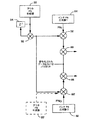
送信変調器52を実現する例示的な信号変調設計を、図3により詳細に図示する。図3において、変調器52は、畳み込み符号化や、受信、誤りの検出や訂正の機能を提供するためのデータシンボルのインターリーブによって、符号化のために、エンコーダ70とインターリーバ72を備える。畳み込み符号化、受信そしてインターリーブに関する技術は、ディジタルデータの送信のために準備する他の技術のように、従来よりよく知られている。この発明の教えによれば、拡散に先立ってディジタルデータを準備する方法に限定されるものでない。それからインターリーバ72からのデータシンボルは、指定された直交コード、ここではコード生成器74より供給されるウォルシュコードで直交して符号化され、覆われる。生成器74からのコードは、1あるいはそれ以上の論理エレメント76を用いてシンボルデータと乗算、あるいは合成される。符号化データと同様に、直交コードのチップレートは、従来より熟練者によってよく理解されている要因により決定される。
【0047】
ウォルシュコードによって覆われる前あるいは後に、またインターリーブされたデータは、乗算器76の入力か出力のどちらか直列に接続される第2の論理エレメント78で2進のPNUシーケンスと乗算される。このシーケンスは、PNコード生成器80によって提供され、そして各ユーザ端末により、あるいは各ユーザ端末について生成された特有のPNシーケンスに一致する。コード生成器80は、この目的のために配置された既知のいろいろなエレメントを用いて構成される。ユーザ端末アドレスあるいはユーザIDは、システムユーザ間で識別するための付加的な要素が提供されるのが習慣であった。これに代わって、データ通信用暗号標準(DES)やユーザ固有キーを用いる暗号化器のような非線形データ暗号化生成器は、要求に応じてPN生成器に代わって活用される。PNUコードは、しばしば高チップレートで非常に長いコードで生成され、それから19200キロビット/秒のような低レートを提供するために間引きする。2進の「0」と「1」の値が、直交コードとPNUコード内のチップを実施するために用いられる時には、乗算器は排他的論理和ゲートのような論理回路によって実現できる。
【0048】
また送信変調回路は、2つのPN生成器82と84を備え、これは、それぞれ同相(I)と直交(Q)チャネルについての2つの異なる拡散コードPNIPNQを生成する。これらの生成器は、適当なインターフェイスエレメントを用いて、いくつかの送信器の間で時間を分割する。このようなシーケンスに関する例示的な生成回路が、1993年7月13日に出願された“高速オフセット調整を用いた2つの長さの疑似ランダムノイズシーケンス生成器の電力”と題する米国特許第5,228,054号に開示されており、この特許は本発明の譲受人に譲渡されており、参考のためにここに組み込んだ。これに代わって、PNコードは、ROMやRAMのような記憶エレメントに、自動的な割り出しと番地付けでテーブルを見つけだす形式のように、予め設定できる。また、これらのPN拡散コードは、いくつかの適用において、90゜位相がずれた同じコードである。
【0049】
また、PN生成器82と84は、適切なPN拡散コードの出力について予め設定した時間の遅れやオフセットを供給する制御プロセッサからのビームあるいはセルの識別信号に一致する1つの入力信号に、少なくとも応答する。拡散コードPNIやPNQを生成する2つのPN生成器だけが図示されているが、より多く、あるいはより少ない生成器を用いて、多くの他のPN生成器を計画して実現できることは容易に理解される。
【0050】
乗算器76から出力された直交符号化されたシンボルデータは、一対の論理エレメントかあるいは乗算器86と88を用いて、拡散コードPNIやPNQによって乗算される。同じデータは、両乗算器に入力され、そして独立したコードによって合成あるいは変調される。それから、この結果の信号は、適当な電力制御増幅回路である、送信電力コントローラ54とアナログ送信機58に転送される。それから、この結果のPN拡散直交符号化出力信号は、一般に単一の通信信号である一対の直交正弦曲線を複位相する変調することにより、RF搬送波上で、一般的なバンドパスフィルタリングされ、そして変調される。しかしながら、この発明の教えで、他の変調を用いることができるのは、たやすく明白になるであろう。
【0051】
この結果の信号は、他のフォワードリンク信号と加算される前に、さらに増幅され、そしてフィルタリングされ、ゲートウェイのアンテナから放射される。このフィルタリング、増幅および変調処理は、従来に置いてよく理解されている。周知のように、他の実施形態は、送信信号を形成するためのこれらの処理のいくつかの順序を入れ替えてもよい。この型の送信装置の処理における付加的な詳細は、前述の米国特許第5,103,459号に見受けられる。
【0052】
また前述の装置と処理は、符号化もインターリーブも施されていないデータがある場合は除いて、パイロット信号を生成するようにしている。代わって、一定レベルの信号は、特有のコードで覆われ、そしてそれから論理エレメント86と88を用いて拡散される。ここで要求されるならば、受信あるいは変化しないパターンの形状の、あるいは不変のフレーム構造のデータは、またパイロット信号を整備するであろう。つまり、一般に、パイロット信号についてのチャネルを形成するのに用いられる直交関数は、すべて1やすべて0、あるいは所々1や0が混ざる構造のパターンでよく知られる受信パターンといった一定値を持つ。代わりに、またこのパイロット信号は、要求されてはいないが、一般に送信電力コントローラ54とアナログ送信機58によって処理される時、ビームの縁の安定した受信のために十分なエネルギを補償するために、より多くの電力が供給される。一旦、RF搬送波上で変調されると、パイロット信号は、要求に応じてゲートウェイにより、各ビームか、あるいはCDMAチャネルに転送される。
【0053】
上述の技術は、地上のセルラや無線システムに有効なPN拡散に要求されるレベルを提供するのに対して、前述したような例示的な衛星中継の際に、ある欠点を持つ。衛星の適用例した時や、あるいは多少複雑にした地上の適用例では、一般に使われるPN拡散コードは、十分早い信号取得を行うには長すぎる。しかしながら、前一般に衛星ベースの中継器に期待されるように、述したようなより長い信号遅延の状態あるいは、より低い電力や減じたパイロット信号で用いる時は、短いPN拡散コードは、実用的な代用として提供されることはない。つまり、より低いパイロット信号あるいは種々の信号パス遅延からなる付加的な問題は、短いPNコードの信号取得における不確実性を増大させ、徐々に取得時間を増大させる。それゆえに、より短いPNコードの適用は、最新の衛星通信システムの設計に実用的に用いられるかは分からない。
【0054】
この発明は、長いあるいは比較的短いPN拡散コードのどちらかを用いた時に結びつく問題を、乗算レベルあるいは「レイヤード」PN拡散技術を採用することにより乗り越える。他の方法を見ると、この発明は、PN拡散コードと特有の識別器あるいはアウタPNコードシーケンスの組み合わせにより、新しく高く特殊化されたあるいは強い拡散コードを生成する。特に、この新しい拡散コードは、取得時間を増大することなく拡散コードのタイムスケールを増大する。この新しい拡散技術は、信用できる方法で信号取得の時間を減じ、スペクトラム拡散通信システムにおけるユーザ端末による通信信号の受信と復調の方法を改善する。
【0055】
この発明で用いられるCDMA通信システムを実施するのに有効な拡散装置の例示的な形態を図4と図5に示す。図4の拡散器では、前述したように、信号合成器あるいは乗算器86と88によって、予め符号化、インターリーブ、そして直交変調されたデータあるいは情報信号が受信される。この点で、はじめの、あるいは「インナ」PN拡散コードPNIとPNQは、前述のようにインナコード生成器82と84から適用される。これは、IチャネルとQチャネルのスペクトラム拡散通信信号を生成する。これらの信号は、はじめのレベルあるいはPNIとPNQ拡散コードによるレイヤで拡散あるいは変調されたと考えられる。しかしながら、スペクトラム拡散信号の転送を送信電力コントローラとアナログ送信エレメントに転送するのに代わって、前に示したように、PN拡散の第2のレベルを適用する。
【0056】
図4に示すように、少なくとも1つの追加のPNコード生成器90は、拡散コードPNIとPNQのタイミングと同期し、ずっと長い期間のPNコードを生成する。このコードは、前述したように周知の装置を用いて生成されるか、あるいは、信号処理の間に、後の訂正のための記憶エレメントに予め蓄積される。
【0057】
上述したように、一般的なインナPNコードは、約1024チップあるいはそれ以上の長さで、約833μ秒の間隔あるいはコード期間にわたって、約1.2288Mcps(メガチップ/秒)のレートに適用される。新しいアウタPNコードは、約255から288のチップの長さで、約240ミリ秒の間隔あるいはコード期間にわたって、約1200チップのより遅いレートに適用される。他のコード長(チップ数に換算して)が明らかにこの発明の教えの範囲内になるが、ここで述べている例示的な形態は、図示する目的のために288チップだけ用いる。インナPN拡散コードよりずっと長いコード期間を持つアウタコードシーケンスが、単に求められる。
【0058】
新しいアウタPNコードのために用いられるシーケンスは、適度な疑似ランダムノイズ2進シーケンスである。例として288チップ長については、最大mのシーケンス(2m−1)は、用いられないが、より長いmシーケンスの一部は用いられ、時々「チョップ」シーケンスと呼ばれる。ユーザによってアウタPNタイミングの取得時間を最小化するために、スペクトラム的に白いシーケンスが好まれるが、しかしこの発明の目的としては求められない。インナコードが「複素」コードであるのに対して、アウタコードは、一般に「実」コードである。
【0059】
コード長は、従来より熟練者に知られるように、特定の通信システムに関係するあるタイミングに関係して選択され、相関器や他の信号取得装置のハードウェア的な制約に従う。つまり、全体的なコード長は、パス遅延とフレームタイミングのあいまいさを解消するように求められる時間の長さに関係して選択されるが、コードチップの長さや期間は、他の要素間で相関器の制約に基づいて選択される。この例として、1つのインナ拡散コード期間(コード長)は、単一のアウタPNコードチップの期間に含まれる。アウタPN拡散コードは、インナPNシーケンス(パイロット信号)や、データとウォルシュ符号(トラヒック信号)を変調して、用いられる最終的な拡散シーケンスを生成する。
【0060】
それからアウタPN拡散コードは、コンバイナ86と88の出力と合成される。この合成は、乗算によって直接生じるのに対して、より大きな範囲の周波数オフセットにわたるパフォーマンスと処理が、差分符号化スキームを用いることにより改善される。この差分符号化は、約2つのアウタPNチップの期間に位相コヒーレントに関する要求を減じる。それゆえに、好ましい形態では、PNコード生成器90からのアウタコード出力は、乗算器92と遅延エレメント94とを用いて第1に差分符号化される。アウタPNコードは、1つの入力として、乗算器92の出力に接続される入力を有する遅延エレメント94から第2の入力を受信する乗算器92に供給される。エレメント94による遅延を用いた値は、アウタPNコードチップレートによって決定されるように、1チップ期間である。このループバック配置は、時間kのアウタPNコード内の各チップと時間k−1(1チップ遅延について)の前のチップとの間の生成物を形成する。これは、付加的なNRZ(+1),NRZ(−1)型で覆うような、コード化されたPNシーケンスを供給する。1つの形態では、「0」の値は、前のチップがないから、第1のチップを符号化するのに用いられる。
【0061】
最初の位の差あるいは差分符号化が、前述であるのに対して、従来に精通する者は、他の遅延や、前述の単一の位よりも高い位の差が用いられることを理解するであろう。しかしながら、これは、チャネルにおいてより長いコヒーレント時間を要求し、そして多くのシステムで有効でないかもしれない。第1の位の差の近似だけでなく、第2の位の差の近似も、いくつかの応用に有効であろう。例えば、DDPSKのような計画は、より少ないコヒーレントを要求するであろう。それゆえに、これは、コヒーレント、差分、そして第2の位の差分の探索を含むように拡張されるはずである。しかしながら、第1および第2の位の差分は、おそらくたいていの応用に十分である。差分符号化されたPNシーケンスは、乗算器92から2つの乗算器96と98のそれぞれに転送される。乗算器96と98は、それぞれ第2の入力として、1つの入力と、PNIあるいはPNQの拡散情報信号の1つとして、符号化されたPNシーケンスをそれぞれ受信する。それから、これらの信号は、差分符号化アウタPNシーケンスによって拡散PNI信号あるいは拡散PNQ信号が共に乗算される。これらは、インナおよびアウタPNコードによってIとQのチャネルについて拡散されたスペクトラム拡散変調信号となる。これらの変調信号は、それぞれ、多重拡散あるいは他の処理で生じた好ましくない信号成分を取り除くための2つのベースバンドFIRフィルタ100Aと100Bの1つを通じて転送される。
【0062】
図5の拡散器において、予め符号化、インターリーブ、そして直交して覆われたデータあるいは情報信号が、以前のように、信号合成器あるいは乗算器86と88によって受信される。しかしながら、最初の、あるいは「インナ」PN拡散コードPNIとPNQは、2つの乗算器96´と98´にそれぞれ適用される。乗算器96´と98´は、それぞれインナコード生成器82と84から、1つの入力として符号化されたアウタPNシーケンスと、2つ目の入力としてインナPNコードを受信する。それから、合成あるいは2つのコードからの生成物は、乗算器86と88に入力として適用される。これに代わって、アウタPNコードは、ダッシュをつけて示されるエレメント90´による差分処理なしに適用される。
【0063】
アウタとインナのPN拡散コードと符号化されたデータシンボルの関係は、さらに詳細に図6に図示される。覆われたデータシンボルは、この例では、チップ長が128で、システムクロックが1.2288Mcpsの拡散コードレートに設定されている。これは、長さ128のコードをチャネル化するのにふさわしいが、64のような他の長さでは、要求されるように用いられる。これは、インナPN拡散コード期間(1024チップ)あたり、(それぞれ128チップの)8コードシンボルとなる。
【0064】
アウタPNコード(チップ)は、インナPNコード期間全体にわたって一定のままである、つまり、1つの一定な値のアウタPNチップは、1024のPNチップの期間をまかなう。それゆえに、正しく同期された検索によって、ユーザ端末は、はじめにインナPNコードタイミングを取得し、それからアウタPNコードタイミングを決めて、要求されたタイミング制御を達成する。しかしながら、アウタPNチップの限界が生じる時は、ユーザ端末は、この接触方法を知るべきであり、十分に近似できる。この情報は、ユーザ端末の受信機が、不正確なタイミングの結果を導いたり、供給したりする境界を越えて信号のエネルギを1つにすることを防止するのに用いられる。それゆえに、図6に示すように、アウタPNチップの限界は、既知のシステムタイミングを用いて、インナPNコード期間の範囲で生じるように調整される。
【0065】
ゲートウェイは、一旦、スペクトラム拡散通信信号を用意し、それらを衛星を通じて送信すると、これらは、種々のユーザによって受信され、適切な信号タイミングが決まる。ユーザ端末の受信し、逆拡散し、そして前述したようなPN符号化技術を用いた通信信号の検出あるいは復号を行う受信機の部分は、図7の一部に図示されている。図7に示すこのユーザ端末は、例えば、これに限定されるものではないが、ポータブルあるいは移動セルラあるいは衛星電話といった無線通信のデバイスとして存在する。
【0066】
図7に図示する受信機の部分は、通信信号を受信して、そしてアナログ受信機あるいは受信システム104に転送する、アンテナ102を少なくとも用いる。受信された通信信号は、アナログ受信機104にてダウンコンバートされ、そして、適当なIFあるいはベースバンド周波数に変換される前に増幅され、そして、フィルタリングされ増幅される。それから、この結果の増幅された信号は、適当なクロックレートでディジタル化され、そして少なくとも1つのディジタルデータ受信機106Aと、少なくとも1つのサーチャ受信機108に出力される。これらの出力は、同相と直交位相のチャネル信号を合成したものであることを明確にするために図示したものであるが、しかし、一般に分けられたIとQのチャネルの形式で示される。
【0067】
付加的なディジタルデータ受信機106B−106Nは、いくつかのシステム設計で随意選択な信号ダイバーシチを行うのに用いられる。従来に精通する者は、用いる受信機の数を決定する、一般にダイバーシチが可能なレベル、複雑さ、製造の信頼性、コストなど、上記数に関する初期選択を提供するのに用いる要因を難なく理解するであろう。サーチャ受信機の数は、1つ以上で、また従来の技術に精通する者によって理解されているように、通信システムの複雑さ、探索されるチャネル数、要求される信号取得速度、タイミング制限などに依存する。
【0068】
またユーザ端末は、サーチャ受信機108と同様に、ディジタルデータ受信機106A−106Nに接続される制御プロセッサ110を少なくとも1つ備える。制御プロセッサ110は、一般に、数ある機能のうち、特に基本信号処理、タイミング、電力およびハンドオフの制御や調整、ダイバーシチ、ダイバーシチの合成機能、そして信号搬送波で用いる周波数の選択を持つ。制御プロセッサ110によってしばしば実行される他の基本制御機能は、信号送信や受信の処理の部分で用いられる、疑似ランダムノイズ(PN)符号シーケンスや直交関数やコードシーケンスの選択や巧みな操作である。これは、様々な信号を取得するのに必要な、位相やPN符号タイミングオフセットを有する。
【0069】
データ受信機106A−106Nの出力は、ダイバーシチ合成器と復号器112に接続され、これは、プロセッサ110の制御下でディジタルベースバンド回路114に信号を出力する。ベースバンド回路は、処理の残りや、情報を他の端末と相互に転送するユーザ端末で用いられる表示エレメントを備える。つまり、一時的あるいは長期のディジタルメモリのような信号やデータの蓄積エレメント、LCDやビデオディスプレイのスクリーン、スピーカ、キーパッド端末、そしてハンドセットのような入出力デバイス、A/D変換エレメント、ボコーダと他の音声とアナログ信号処理を行うエレメント、従来より知られるエレメントを用いる加入者ベースバンド回路のすべての形成部品である。図7に示すように、これらのいくつかは、制御プロセッサ110の制御下で、場合によっては通信中に制御される。
【0070】
特定のディジタルデータ受信機を通じた通信リンクを確立、あるいは維持するために、1つあるいはそれ以上のサーチャ受信機108が、予め設定されたPNコードとコードタイムオフセット、そしてドップラ周波数空間に基づいて、信号を取得するために受信した通信信号をくまなく調べるように設定される。つまり、アナログ受信機から受信したデータを定期的に探索し、パイロット(あるいは他の要求される信号)が存在するかどうか決定する、あるいは受信された信号がその次の信号の受信と復号に用いるのに適切なパイロット信号であるかをはじめに決定する。多くのシステムでは、最も強い信号は、パイロット信号であるが、しかし、これは要求されたものではなく、おそらくいくつかの衛星通信システムに関する場合ではない。つまり、パイロット信号は、適正かつ効率的、迅速な追跡と取得を引き受ける一般的なトラヒックチャネル信号に比例する付加的な電力が割り当てられる。しかしながら、発明の処理は、PNコードタイミングが適正な間、パイロット信号であるか否か、あるいは弱いパイロット信号であるか否かによらず、必ず最も強い信号を用いることができる。
【0071】
パイロット(あるいは他の)信号タイミングが取得された時を決定する1つの方法は、パイロット信号PNコード位相の「仮定」として算定された位相オフセットを確立、あるいは選択し、それから、これらを、通信信号と、伴って生じる雑音とを局地的に生成されたリファレンスPN拡散コードに、そのタイミングオフセットを適用したものを用いて逆拡散することにより、テストする。それから、関連のある信号内の信号チップからなるエネルギは、予め設定された時間にわたって統合され、そして1つあるいはそれ以上の予め決められた閾値と比較される。蓄えられたエネルギは、ローカルリファレンスと信号PN拡散コードが同じタイミングの時、最大となるか、あるいは少なくともある閾値を越える。
【0072】
PNコードタイミング探索を決定するエネルギ測定に有用な装置は、時として検定統計量の計算と呼ばれ、1996年11月19日に出願された“多元ウォルシュチャネルを用いたマルチユーザ通信システムにおける信号取得”と題する米国特許第5,577,025号や、“CDMA通信システムにおける探索取得を行う方法と装置”と題する米国特許第5,644,591号に開示されており、この特許は本発明の譲受人に譲渡されており、参考のためにここに組み込んだ。
【0073】
新しいアウタ拡散あるいはPNコードを用いる信号取得のための例示的な装置を図8に図示する。この装置の操作は、前述に参照される特許に開示される装置を用いるように、2つのPNコードあるいはコードセットの一番奥がすでに取得されたものと仮定する。つまり、ユーザ端末回路は、インナPNコードに関する適当なタイムオフセットをすでに決定している。このような第1のレベルの信号取得の後に、算定されあるいは決められた、インナPN拡散コードに関するタイムオフセットは、それから、インナPNコードに関する受信信号の逆拡散に用いられて、アウタPNコード拡散データシンボルとして供給される。
【0074】
逆拡散は、局部的に生成されたPNI-inner拡散コードとPNQ-inner拡散コードを、逆拡散器あるいは相関エレメント120に入力として入力することによって行われる。それから、これらのコードは、予め決められたインナPNコードタイムオフセットを用いて、受信通信信号として適用される。逆拡散器120の出力は、一対のアキュムレータあるいは累積加算エレメント122Aと122Bに入力される。アキュムレータ122Aと122Bは、IかQのどちらか一方のチャネルについて逆拡散器の出力を、インナPNコードの期間にわたって累積する。各アウタPN「チップ」期間は、インナPNコード(シンボル)期間にわたって、延長するから、シンボルエネルギは、この期間にわたって累積し、各アウタPNコードチップについてのエネルギを提供する。図8に示すIkとQkの値は、k番目のIとQのアウタ拡散コードPNチップに相当し、これは、例示的な形態では、1024のIとQのインナ拡散コードチップを累積することによってなるものである。他の拡散コード長は、結果として、他の異なる蓄積期間あるいはチップ数に一致する。
【0075】
アウタPNコードをIkとQkの値から取得するには、ユーザ端末の受信機は、はじめに、信号のフィードフォワード差分復号を行わなければならない。この復号が達成するための例示的な技術は、一般にデータ復調で用いられる内積構造を用いる。上述の構造や、データ復調についてのその操作は、“パイロット搬送波内積回路”と題する米国特許第5,506,865号に開示されており、この特許は本発明の譲受人に譲渡されており、参考のためにここに組み込んだ。
【0076】
上述の特許に開示される技術において、内積は、パイロット信号から導かれるデータ信号ベクトルとリファレンスベクトルの間で形成される。一般的なデータベクトルは、直交チャネライズコードの長さである64あるいは128チップのシンボル長を有する。しかしながら、データ信号の受信環境が一定なら、現在の「シンボル」期間は、1024インナチップであり、そして最新の(Ik,Qk)信号ベクトルは、リファレンスベクトルよりむしろ、前の信号ベクトルを内積がとられる。同じアウタPNコードは、IとQの両チャネルで用いられ、そしてこれらのチャネルのうち一方における1つのアウタPNチップの平均値(チップエネルギE)が下式となる。
【数1】

ここで、ECは、受信された信号チップのエネルギ、E{IK}は、Iチャネルの平均値、E{QK}は、Qチャネルの平均値である。
アウタPNチップkに関係する内積は、下式となる。
dk=IkIk-1+QkQk-1
アウタ拡散コードPNチップkが前者k−1と同じ時、dkの平均値は、単に(1024)2Ec(コード長2乗時間チップエネルギ)である。しかしながら、もし、アウタPNチップが互いに異なると、dkの平均値は、−(1024)2Ecで、要求される差分復号が達成される。
【0078】
内積処理を用いた受信チップの差分復号は、図8の左側に概略的に示されている。アキュムレータ122Aの出力は、乗算器124Aに1つの入力として供給され、そして、アキュムレータ122Bの出力は、乗算器124Bに1つの入力として供給される。また同時に、アキュムレータ122Aと122Bの出力は、それぞれ一対の遅延エレメント126Aと126Bに入力として供給される。これらの遅延エレメントの出力は、順にそれぞれ第2の入力として乗算器124Aと124Bに供給される。遅延エレメント126Aと126Bは、乗算器に入力する前に、IKとQKの信号に関する1つのアウタPNチップ期間に遅延を与える。これにより、乗算器124Aと124Bにて、各PNチップkとその前者との間の生成物を形成する。
【0079】
それから、乗算器124Aと124Bによりk番目とk−1番目のIとQのチップについて形成された生成物は、差分符号化して転送されたアウタ拡散コードPNに相当する内積値dkを生成する加算エレメントや加算器128を用いて、互いに加算される。それから、復号されたPNコードチップシーケンスdkは、アウタPNコードのローカルバージョンの異なる時間のオフセットに反して、関連づけられる。なぜなら、アウタPN拡散コードは、およそ240ミリ秒のより長い期間を持つから、単一のアウタPN期間(288アウタPNチップ)内で適切な配置を探索する確率を最大化することは重要である。さもなければ、重要な時間の総量は過ぎて、そして本質的に、次に期間が始まるのを待つ間、さらに信号処理を行うことに無駄に費やす。
【0080】
これは、マッチトフィルタの扱い方が相関処理を実施するのに有用であることを示唆している。概念的に、マッチトフィルタは、Wメモリエレメントのタップされた遅延ライン、つまりフィルタ長Wである。このタップ重みは、アウタPNの最初のWビットで、重み付けされた出力のすべてのWは、新しいアウタ拡散コードPNチップが受信されフィルタ内に取り込まれる毎に、アキュムレータによって加算される。それからアキュムレータの出力は、閾値と比較される。閾値を超えたフィルタ出力は、アウタPN拡散コードの適切な配列を明らかにする。マッチトフィルタを用いると、1あるいは2期間内でパイロットを取得する可能性は非常に高いはずである。より長いフィルタは、短いフィルタより、探索の確率に優れるが、実現コストがよりかかる。
【0081】
このマッチトフィルタの扱い方は、図8に示され、ここでは、マッチトフィルタ130は、入力としてシーケンスdk値を受信するように接続され、そして相関出力を比較エレメントあるいは比較器136に供給する。比較器136は、フィルタ130からの相関出力が要求される閾値を超えたときは、出力指示を生成する。比較器136の出力は、アウタPN拡散に用いられる選択されたタイミングオフセット値が適切な時、選択あるいは指示する既知の探索と取得回路と共に用いられる。
【0082】
前述の例では、アウタPNチップの中間到着時間は、0.833ミリ秒で、従来に精通したものに知られる種々のハードウェアかソフトウェアのエレメントのどちらか一方を用いてマッチトフィルタがフィルタリング操作を実施することを可能とする。例えば、サーキュラバッファは、このフィルタを実現するのに用いられる。
【0083】
なぜなら、各アウタPNチップは、1024のインナPNチップの和から導かれるから、アウタPNチップは、インナPNチップに関する30dBの「処理利得」から利益を受ける。この利得は、アウタp自動相関機能(ACF)のピークとオフピークの間の差の最大値(Rmax)が、インナPN拡散コードについての場合より、取得性能を決定するのにさらに重要であることを表している。最も大きいオフピークACF値のいくつかだけは、雑音の付加によって閾値を超えるのに十分大きい。それ故に、アウタPNコードを選択するのに関わる主の基準は、適正な部分的相関ウィンドウサイズ(すなわちマッチトフィルタ長)に関する最大オフピーク相関値で最小化される。
【0084】
なぜなら、アウタコードチップは、インナコードチップより長い約1000(1024)まで続くから、24のアウタチップに基づく相関は、24のインナチップに基づく相関より信号エネルギが大きい1000回を統合する。さらにより長い、仮に約2048チップのインナコードにわたって統合されれば、信号エネルギをさらに10回以上供給するだろう。相関処理への相対的な効果の例を、図9に示す。図9においては、曲線162が、より短いアウタPNコードを用いるマッチトフィルタを用いた時の応答を示すのに対して、応答曲線160は、より長いPN拡散コードを用いた時の例示的な相対的なピークとオフピーク応答を示す。この利益は、非常に明白である。
【0085】
前述のマッチトフィルタの探索配列は、平均受信アウタPNチップエネルギに関して計測された時だけ、適正に働く。単純であるが効果的な閾値の設定方法は、(1024)2WEcの配列の時の平均相関結果と(1024)2RmaxEcの誤った配列の時の最大平均結果との間の中程の値に設定することである。
【0086】
一般にこの型の閾値を設定することは、自動閾値制御(ATC)のいくつかの形式が、閾値を正しく較正するのに用いられることが要求される。このようなATCは、内積出力の大きさが(1024)2Ecの判定を生成するから、比較的、実現しやすい。これらの出力サンプルは、単なるフィルタに送られ、ここで、多少の雑音を取り除くために平均化され、そして要求される閾値を生成する(W+Rmax)/2の要素によって計測された平均となる。この手法は、図8下段の右側に図示され、ここでは、また大きさ情報エレメント132が内積値dkのシーケンスを受信するために接続される。大きさ情報エレメント132は、受信した入力シーケンスの相対的な大きさを示す出力を生成する。それからこの大きさは、閾値フィルタ134に入力として供給され、ここで順に、値が平均され、この結果は、要求されるリファレンス閾値を生成する(W+Rmax)/2の要素によって平均されて計測される。それから、このリファレンス閾値は、比較器136に入力として供給される。これに代わって、大きさエレメント132と閾値フィルタ134は、1つまたはそれ以上の付加的なマッチトフィルタ(図示しない)と、閾値との比較よりも複数のマッチトフィルタ出力間の比較による探索で置き換えられる。例えば、マッチトフィルタ出力は、全部のアウタPN期間について選択され、そしてそれから最も大きい出力値が選択される。
【0087】
この発明を実現するのに考えられるべき、いくつかの別の側面がある。第1に、時間と周波数の追跡器が、インナPN拡散コードのタイミングを追跡するユーザ端末受信機で用いられる。このような周波数追跡器の使用は、前に参照した信号取得特許でさらに詳細に論じられている。これらの追跡器は、アウタPN取得の前に従事させられ、操作する。これは、用いられる1024長の取得にわたって、信号をできるだけコヒーレントに保つ。これらの追跡器は、アウタPNチップ境界を越え、あるいはこの境界外にわたらないように、これらの取得を設定することにより、アウタPN変調に影響しないように作られる。しかしながら、パイロットフィルタは、望まれるようにアウタPN変調に影響しなくないから、このような周波数追跡器は、逆拡散器からの直接入力を受信すべきである。
【0088】
第2に、アウタPN拡散コードのローカルバージョンの生成は、アウタPN取得の間、止める。一旦、アウタPNタイミングが決定されると、それからローカルアウタPN生成器は、アウタコードを受信データから取り出し始める。
【0089】
第3に、アウタPN拡散コード取得は、周波数追跡器がほとんど一様な操作の状態になるまで、始めるべきではない。もし、追跡器がまだ過渡的なモードにある時に取得が始まったら、周波数誤りの変化としてEcに見られる変動のため、閾値の較正は有効にしてはならない。閾値が有効になった時のいくつかの決定方法が、一般に必要とされる。潜在的に、確認ステージからの測定は、Ecと相当する閾値とを算定するのに用いられる。それから、アウタPN取得は、実際の閾値がこの算定の90%に達するまで、可能にされない。一旦、内積値が有効であると見なされると、WアウタPNチップの遅延は、また探索閾値テストが可能にされる前にマッチトフィルタを「ロード」するために、許される。
【0090】
前述したこの発明に実施形態は、信号取得に関して従来に対する進歩を述べたのに対して、特定のアウタPN拡散コードシーケンスを用いることにより、さらなる改善が成し遂げられることが発見される。つまり、あるシーケンスあるいはアウタPN拡散コードを構成するシーケンスの型は、この発明の技術を適用するときに、さらに性能が改善される。発明の解析とそのようなシーケンスの使用は、以下を提供する。
【0091】
一般に、Wのサイズの増大や適当なコードの選択は、誤りの確率(失敗と疑似警報)を小さくする。しかしながら、Rmaxの値がWの増加に伴って増加するならば、通信システムの性能の改善は、Wのサイズの増加のように非常に限られるから、適切なコードの選択は、重要である。これは、以下に示す式により失敗の確率を算出する近似を用いることで見受けられる。
【数2】
ここで、I0は、有効な信号の受信に基づく干渉信号レベルである。
もし、Ec/I0とNについての値、インナPNコードの長さが固定され、そして一定となる項のすべてが信号一定Cと合成されるならば、この関係は、以下の単純化された式に換算される、
【数3】
各アウタPN期間に疑似警報に関する複数の機会があり、そして、この機会における統計量が自動相関機能の対応する値に応じて変化するから、疑似警報の確率を正確に算出することは、さらに難しい。しかしながら、疑似警報の確率は、失敗の確率のように、(W−Rmax)/√Wの関数として減少することは、確かな真実である。とても雑な近似として、疑似警報の確率は、疑似警報に関する複数の機会のために、同じくらいの大きさのオーダによって、Pmissより高いと言われる。疑似警報の確率をより正確にはっきりさせることは、一般にシュミレーションに頼るのが一番良い。
【0094】
前述の第2の関係を監視することより、Wをできるだけ小さく保つ間に、一般にWとRとの間の差を最大化することで最も良い性能を引き出せることが分かる。もちろん、Wを小さく保つことは、またハードウェアの観点からも望ましい。
【0095】
最良のコードは、部分的な信号に基づく基準の選択やすべての相関の代わりにコード相関を用いることにより、この発明で最良なコードが選択される。長さ288の2進シーケンスを可能とする2288すべてにわたる徹底的な探索は、いつでもユーザ端末が信号を取得したがるようにするものではないが、しかしふさわしいコードを見つけるための通信システムの設計が行われる間、1度あるいはそれ以上、なされる。このような探索は、さもなくば、過度に長く、そして望まない通信遅延として存在する。それ故に、最善より幾分小さいが、非常に有用、あるいは効果的な近似が開発された。
【0096】
この技術あるいは近似に関して、長さWのマッチトフィルタがはじめに選ばれる。それからコードは、構造[A A A … B]を用いて長さWの部分列から生成、あるいは組み立てられる。例えば、Wが24チップ(マッチトフィルタ長24)の長さを持つように選ばれると、全PNコード長は288チップである。それから、「A」と「B」の部分列は、共に長さ24で、「B」は、合計11回[すなわち(288チップ−24チップ)/24チップで、11の「B」の使用となる]だけ表れる。それから、マッチトフィルタは、受信機はいつも、全288コード長の24アウタチップの部分列に対して、「A」の相関をとるから、「A」の部分列を用いて組み立てられる。これは、全シーケンスを用いて相関をとるより、ずっと早い操作である。
【0097】
ユーザ端末受信機のタイミングがアウタPNコードと適正に設定される時、得られる相関値は、「A」あるいは「B」の選択に関係なくW(24)である。つまり、相関値は、設定された信号および設定されないときの0についてWの全受信チップを反映する。1つの目標は、「A」と「B」の周期的な相関のすべてが最小化し、そして、繰り返すPNコードの過渡の領域あるいは部分「AB」と「BA」でのAの相関がまた最小化するような「A」と「B」についての値を選択することである。出願人はが「B」の部分列についてのチップ値の効果的な選択は、「+1」あるいは「−1」のどちらかのすべてのチップを作ることであることを発見した。この近似は、最良の「A」についての徹底的な探索を行うことを可能にし、大き過ぎないWを供給し、そして比較的容易に生成するアウタ拡散コードを生成する。
【0098】
前述の探索技術の形態は、Rmaxが0の時の長さ24(W=24)に一致する非常によいコードの証明を導く。見分けられたコードは、mシーケンスあるいは疑似ランダムノイズの探索を切りつめるように、他の試された技術によって発達したコードより小さい(W=24について)大きさのいくつかの次数の誤りの確率を生成する。−21dBのEc/I0において、疑似警告の10-4未満の確率は、失敗に関してさらに小さい確率で期待できる。それゆえ、以下に述べるコードを用いることは、小さな誤りの確率とマッチトフィルタをできるだけ短く保つことの間のよいトレードオフとして見ることができると信じられる。
【0099】
このコードの最初の24ビット、いわゆる「A」部分は、
[ -1 -1 1 -1 1 -1 -1 1 1 -1 -1 -1 1 -1 1 1 -1 -1 -1 -1 -1 1 -1 1 ]
で、残りビットのすべてと「B」の部分は「1」である。「1」を「0」に、そして「−1」を「1」に写像することは、アウタPNが、蓄積と訂正で以下のような、もっとコンパクトな8進法形式に変換できる。
6 5 4 7 2 3 7 2 0 … 0
つまり、+/−1の形式は、相関と干渉を調べるのに有用であるが、PN生成器は、通常、0,1の形式に基づいており、8進コードは、符号化システムに共通して用いられる。
【0100】
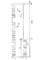
フィルタ処理に関して288チップ期間にわたる、このようなコードのタイミングの零を図10に図示した。図10において、有用なアウタコード170は、264チップあるいはビットの一定値「1」の部分174が続く24ビット可変部分172を用いて示される。また、比較のために、この発明を実現するのに有用であるはずのより長い疑似ランダムノイズコード176の部分は、後述するように示される。
【0101】
図4に示したようにデータ上で操作するハードウェア内でエンコードされていないバージョンを蓄積し、そして差分符号化器を提供するよりはむしろ、ゲートウェイ送信回路内で差分コード化アウタPNコードあるいはシーケンスを蓄積する方がさらに便利である。これは、ゲートウェイによって処理される多くのチャネルそれぞれについて、乗算器92と遅延エレメント94を削除することによってハードウェアを縮小する。この削除を達成するために、慣例では、{1,−1}の記法で1を初期設定し、あるいは{0,1}の記法で0を初期設定する送信機で用いられるメモリや蓄積エレメント内で差分符号化されたシーケンスを蓄積することが採用される。このアプローチと差分コード化されたPNコードの蓄積を用いて、前述から、このシーケンスの最初の差分符号化された24ビットは、以下のようになり、残る264ビットあるいはチップは「−1」である。
[ -1 1 1 -1 -1 1 -1 -1 -1 1 -1 1 1 -1 -1 -1 1 -1 1 -1 1 1 -1 -1 ]
あいにく、このアウタPN拡散コードの差分符号化バージョンを蓄積するのに小さな欠点がある。アウタPNコードの1つの完全な期間にわたって差分符号化を仕上げた後、送信機あるいは差分符号化メモリの状態、すなわち蓄積される値は、アウタPN期間の始まりに存在するものの反対である。これは、繰り返しアウタPNシーケンスをコード化することが、2×288チップの周期性を持つ差分コードシーケンスを生成し、残りの半分のシーケンスが最初の半分を補足するものであることを意味する。
【0102】
様々なアプローチが、この小さな複雑さを説明するのに用いられる。第1に、エンコードされていないアウタPNコードは、1つの期間にわたって蓄積され、そしてリアルタイムで差分符号化される。第2に、差分符号化されたアウタPN拡散コードの全2×288ビットは、1つのアウタPN期間にわたって蓄積される。第3に、符号化されていないアウタPNコードシーケンス内の48ビットと264ビットの間のどこかで、単一のビットが値内でトグルされる。この単純な動作は、Rmax=0を保持し、そして符号化されたアウタPNの期間を288ビットに等しくする。第4に、符号化されていないアウタPNコード内の24ビットは、トグルされる。この動作は、264のひとつなぎの「1」を保持し、符号化されたアウタPN拡散コードの期間の288ビットに等しくする。しかし、性能は、Rmaxが今2に等しいから、この後者の技術で犠牲になる。
【0103】
Wが24に等しいとき、前述したアウタPNコードは、Rmaxは0に等しくなるが、|R|maxは8に等しい。もし、いくつかの理由で、|R|maxについての小さな値で、アウタPNコードを用いるのに望ましくなくならば、以下の8進形式か2進形式は、|R|maxの値を4に等しくする。
7 1 3 2 1 0 7 7 7 … 7
[ -1 -1 -1 1 1 -1 1 -1 -1 1 -1 1 1 1 -1 1 1 1 -1 -1 -1 -1 -1 -1 -1 -1 -1 1 1 1…1 ]
シュミレーションは、前に選択されたPN拡散コードと図8の取得回路を用いて実行される。Ec/I0が−22dBと同じくらい低い強さのパイロット信号を用いる時でさえ、誤りの確率は、あまりに小さいので、10万回の試行で生じる単一の誤り、失敗や疑似警報のどちらでもない。つまり、システムが不正確にPN拡散コードタイミングが正しいか正しくないかをそれぞれ示す確率である。3.4×10-6のオーダでのEc/I0が−22dBで、ATC方法についての分析的な近似が失敗の確率を算出した。Ec/I0の値がさらに−25dBに減じた時、失敗の確率に関する解析的な近似は、約1×10-3であった。ATC方法を用いた時、10万回の試行に相当する結果は、約2.6×10-4の失敗の確率と、約7×10-4の疑似警報の確率であった。最大値を取り出す方法を用いた時、前を参照すると、10万回の試行で、失敗の確率は、1×10-5未満であり、疑似警報の確率は、1×10-5未満である。つまり、失敗や疑似警報が無い状態は、10万回の試行に見られる。
【0104】
さらにより小さい誤りの確率が望まれるなら、1つのコスト効果アプローチは、第2の観察テストを要求することである。これは、単に、生じたアウタPNコード探索の後に288アウタチップの期間の間待ち、そしてタイミング決定テストを繰り返すことにより容易に実現される。タイミングの独立したテストの両方で疑似警告となる確率は、単一の観察の疑似警告確率の2乗である。例えば、Ec/I0が−25dBにおけるATC方法で第2の観察を用いると、疑似警報の確率が7×10-4から約4.9×10-7に変化する。このような第2の観察に関係する時間のペナルティは、240ミリ秒である。
【0105】
前述のPNコードは、短いランダムな観察部分、24チップ長、および264チップの長い一定部分からなるアウタPNコードとなる。また、観察される代わりのPNコードは、疑似ランダムノイズを全288チップ長にわたって観察し、そしてmシーケンスを切りつめるように単に形成される。
【0106】
このアウタコードは、長さ511のmシーケンスから切り取られた部分列である。特徴的な多項式は下式で示される。
Q(z)=1+z3+z4+z6+z9
コードのような生成のための例示的な生成構造は、図11のガロアLFSR設定で示される。初期状態(レジスタの中身)は、[000010010]であるべきである。選択されたシーケンスの最初の9チップは、左端を最初のチップとして、「010000110」である。この生成器は、288クロックを計時氏、そしてそれから、要求されたコードシーケンスを提供する最初の状態にリセットする。つまり、アウタPNシーケンスは、288チップ、あるいは1アウタチップ期間を繰り返す。
【0107】
これは、相関ウィンドウサイズ48において最大12のオフピーク相関を持つコードとなる。これは、長さ24のマッチトフィルタについて特に最高の状態にされた以前のコードより、より性能を発揮する。この切りつめていないコードは、Simon著の「スペクトラム拡散通信」第1巻の表5.8に見られる。
【0108】
しかしながら、前述の形態で用いられるマッチトフィルタ探索方法は、この代わりのPNコードでは十分に役割を果たさないかもしれない。例えフィルタ長が約2倍の48ビットであったとしても、正しい信号タイミングを検出しない確率(1−Pdetect)は、固定された疑似警報の確率を与える、代わりのコードについての大きさのオーダより大きい。それゆえに、PNコード取得回路についての他の形態を以下に示す。基本的な概念は、差分復号エレメント124A、124Bおよび128の出力からアウタPNチップのブロックを集め、そしてそれからアウタPN拡散コードについてのローカルリファレンスのすべての可能な配置に対して、このブロックの関連づけする構成からなる。個の相関プロセスを達成する信号取得のアーキテクチャを図12に示す。
【0109】
図12では、信号取得装置の逆拡散と差分復号の部分が、図8に示した配列から変わっていないままである。しかしながら、アウタPNコードチップdkを受信するマッチトフィルタ130は、今、バッファ140とブロック相関器142で置き換える。バッファ140やブロック相関器142で用いられるブロックデータのサイズは、従来より知られるように、明確な適用や通信システムの操作パラメータに従って決定される。つまり、回路の複雑さやデータのブロックの処理の時間、および取得の速度や正確さに関する要求が、これらのサイズを決める。
【0110】
図示の目的のためだけに、48チップのサイズが、この形態で論じられる代表的な値として用いられる。この例では、バッファ140は、48のアウタPNコードチップ、あるいは48のアウタチップ期間にわたるチップを集め、それからこれらをブロック相関器142に処理のためにブロックデータとして転送する。一旦、データはブロック相関器142の外に転送されると、受信を開始し、次の48アウタチップをバッファする。
【0111】
例示的なブロック相関器142のより詳細な描写が、図13に図示されている。復号されたアウタPNコードチップのブロックが相関器142に転送されると、独立したチップは、データブロックと呼ばれる蓄積あるいはメモリエレメント144にDATA(47)を通じて連続した目折りの位置DATA(0)に蓄積される。アウタPNコードのローカル2進(このモデルでは+1/−1)のコピーが、アウタコードブロックと呼ばれるメモリエレメント146のPN(287)を通じた連続するメモリ位置PN(0)の系列に蓄積される。これらの各ブロックは、アキュムレータ148に入力として接続される出力ラインあるいはバスを持つ。データブロック144の出力は、アキュムレータ148へのデータ入力が指示され、そしてアウタコードブロック146の出力は、アキュムレータ148の加算/減算制御入力が指示される。
【0112】
PNアウタコードブロック146から回収された2進値は、データブロック144から回収された最新のデータ値が、最新のアキュムレータの中身と加算あるいは減算されたか否かを決定するために、アキュムレータ148の加算/減算ラインを制御するのに用いられる。アキュムレータ148は、各ローカルPNコードオフセットタイムにおいてローカルPN拡散コードとデータとの相関を計算あるいは生成する。一般に、1つのタイムオフセットは、データを通じて288の各パスについて試される。
【0113】
最も大きい相関値とそれに対応するインデックスは、他のメモリ位置150に蓄積され、ここで、アキュムレータ148の部分を形成する。それから、このインデックス値は、適正なアウタPN拡散コード配置の最良の見積もりとして、コントローラ110あるいは、他の信号取得回路に報告される。この処理で用いられるステップの疑似ランダムコードの表現は、以下で示される。これらのステップは、復号されたアウタPNコードチップの新しいブロックがブロック相関器142に転送される毎に、繰り返される。
【0114】
ブロック相関器142にて行われる処理ステップは、以下の疑似ランダムコードのステップで表される。
RmaxとRmax_iの値を「0」の設定する。
For Ri = 0 to 287
R = 0
For j = 0 to 47
R = R + Data(j) * PN( (Ri + j)mod 288 )
End For
If R > Rmax
Rmax = R
Rmax_i = Ri
End If
End For
これは、R、Rmax、Rmax_iの値を0に等しくする最初の設定によってデータを処理し、ここで「i」は、特定の時間に関するインデックス値あるいはコードに関する位相オフセットである。つまり、コードによるチップの数は、オフセットである。それから、0から287まで変化する各Riについて、Rの値は、以下の関係式に従って、jが0から47までの48データの値それぞれについて決定される。
R = R + Data(j) * PN( (Ri + j)mod 288 )
各時間Rは、Rmaxと比較され決定され、もし決められたRの値が最新の蓄積されたRmaxの値より大きいならば、その時は、RmaxにRの値と等しく設定し、そしてRmax_iは、Riに等しく設定される。それゆえに、各時間でRがRmaxを超えるなら、このRの値は、新しいRmaxの値として選択され、そして生成されたRiの値は、Rmax_iとして記録される。処理の最後には、Rmax_iについての値が要求されたタイミング情報として提供される。
【0115】
第1の申し込まれたPNコードに対する第2のそれの1つの欠点は、第1にメモリや関係するストレージと訂正の回路を形式において、活用するためのハードウェアを必要とすることである。このPNコードはまた、復号されたアウタチップのバッファと処理を行うブロックのために、より高い相対的な計算レートを必要とする。同時に、より長いブロック長を用いる時でさえ、(信号ブロックに基づく)探索と疑似警報状態は、第1の申し込まれたPNコードを見つけるのと同じくらい良いかそうでないかもしれない。しかしながら、おおよそ等しいことが期待されるが、代わりのアウタPNコードの伸張性と、すべてのアウタPN期間を待つことなく繰り返される探索の機会が、付加的な計算機の複雑さの価値のある。それゆえに、もっとランダムなアウタコードは、特別なコード[ABB…B]の代わりに用いることができる。これは、Wが48のより長い相関ウィンドウがまた使用できることを意味する。PNコードの適切なテーブルは、文献より見つけられるほど十分に長いことが分かる。テーブルからのコードの1つは、Wが24の時に一致する特別なコードの性能に等しい(あるいは少しだけ良い)性能を発揮する。
【0116】
前に述べたように、アウタPNタイミングについての第2の監視、あるいは適正なタイミング取得を確かめる配置、あるいは第1の申し込まれたPNコードの配置をとることは、PNコードの「B」の期間と「A」の部分の再読込を通じて待つことが求められる。つまり、アウタPNコードの面白い部分までほとんど240ミリ秒(アウタPNコード期間)のパスは、再びもう一度マッチトフィルタ130に読み込まれる。代わりのPNコードのアプローチでは、第2の監視は、復号されたアウタPNコードチップのちょうどその次のブロックで用いられる。例えば、48の復号されたチップのブロックサイズを用いれば、相関のテストの処理あるいは処理すること(288のデータパスのそれぞれをテストする)は、1つのアウタPN期間の間、何度か繰り返される。取得させる能力は、代わりのPNコードを用いた単一のテストによって一般に提供される付加的な計算機の複雑さを埋め合わせる以上に、効果的に待つ期間なく繰り返すテストに基づいて決定される。
【0117】
もっとランダムなアウタPNコードを用いることの付加的な利点は、代わりのアウタPNコードのすべての部分が情報を運ぶことである。これは、復号されたチップのいかなるブロックも用いられるから、代わりのアウタPN拡散コードは、バースト誤りの環境でもっと強くなる。これに対して、第1の申し込まれたPN拡散コードの「A」に限られた部分だけは、使用される。加えて、長い固定された部分を用いるPN拡散コードは、ここでは長さNが24のマッチトフィルタを用いて性能を最高にするように特に設計されているから、のばせない。メモリや相関器のブロックサイズなどを増大するような、取得回路の部分の変更が行われたままならば、コードの「B」の部分は、可変できず、性能を改善できない。しかしながら、すべての長さにわたってもっと正確な疑似ランダムノイズである代わりのPN拡散コードは、修正する義務がもっとある。
【0118】
前の状態で、この操作は、インナコードの「第1」とアウタコードの「第2」は必要でない。「第1」と「第2」の使用は、図示の明確さと説明の表記の利便差を目的とする。いくつかの特別に仕立てられた、2つのコードを生成する特徴を持つ新しいより長いコードを生成するに従って、これは、実際、事実上見られる。送信側(送信機)あるいはデータ復調器に関する操作の順番は、どちらかの方法、つまり、どちらかの順でこれらの拡散シーケンスを適用することにより、行われる。インナコードの最初は、データに、それからアウタコードに適用され、あるいはアウタコードと、それからインナコードを適用する。代わりに、操作は、その時、拡散に用いられるコードの別の組み合わせとして行われる。しかしながら、サーチャ受信機は、行われる操作の順序に影響されやすい。ここで、インナコードは逆拡散され、あるいは最初に逆拡散するのに用いられる。つまり、それは、サーチャにおける取得目的に関して問題となり、ここでそれはインナPNコードの第1とアウタPNシーケンスの第2である。
【0119】
取得処理が「2つのステップ」の処理で、時として発明者によって「クリンチング」と呼ばれることを明確にすべきである。実際は、無線のデバイスあるいは電話の第1は、即座にインナコードを取得し、そしてその後、アウタコードを取得する。この「2つのステップ」のアプローチと用いることは、仮定の数が大きく減じることを意味する。これは、通信システムにこのアプローチを用いるための基礎になる誘因を提供した。
【0120】
1つは、インナとアウタのコードのタイミングの認識が無くて始めても、取得について考えることができる。インナコードのたくさんの仮定は、コードタイミングが見つかったと信じられる間でテストされる。かなり少ない仮定があり、そしてこれは時間のビットを取得する。アウタコードは、この時間の間、全く無視される。この点で、インナコードタイミングは、1チップが決定し、1024チップが曖昧な状態、例えば、相当する曖昧な値を生成する他のインナコード長で取得される。それから、良い仮定(コードの同期一致)があると信じられ、受信波形が、検出あるいは見つけられたインナコードで逆拡散する後のアウタ検出器に入力される。アウタ検出器は、アウタオフセットが何であるかを決定して、その結果、いくつかの付加的なタイミング情報となるか、あるいはこれを供給する。この第2のステップは、1024チップの決定(インナコード長)と1024×288チップの曖昧さ(インナタイムアウタコード長)を用いて、タイミングを達成する。この全体的な結果は、1チップの決定と294912チップの曖昧さのタイミングを持つことである。
【0121】
通信システムでアウタコードが達成するものを再強調し、アウタコードが例示的なチャネル化や、ユーザやユーザ信号の分離を行わないことを指摘すべきである。2つのPNコードの組み合わせが、通常のセルラリバースリンクで用いられる時、ロングコード(拡散コードではない)は、チャネル化を行う。ここで、アウタコードは、インナコードのみを用いて効果を上げるより、より長い時間のスケールを用いて効果的に通信システムを提供する。それは、重要な取得時間を増大することなく行う。この結果のより長いタイムスケールは、少なくとも2つの効果を提供する。第1に、周期的冗長検査(CRC)のような、複数のフレームタイミングの仮定をテストする、たくさんのエラーメトリックの計算を必要とすることなくフレームタイミングを提供する。第2に、アウタPNオフセットにより、ビームの曖昧でない確認を許容する。インナPNコードは、あまりに短い(要求される長さと期間が用いられる時)ので、パスを確立するパス遅延の変化に比例できない。
【0122】
取得時間についての効果は、タイミングが2つのステップで取得できるので、最小化されることである。はじめに、インナコードタイミングが可能なn=1024が試され、そしてそれからm=288のアウタコードタイミングが試される。それゆえに、n+mのトータル1312の仮定が試される。インナコードが単にタイミングの曖昧さを解決するのに十分長く作られるならば、n×m=294912の仮定をテストする必要がある。言い換えれば1つの軸が1024インナオフセットで、残る軸が288アウタオフセットである、タイミングの仮定の2次元グリッドについて探さなければならない。しかしながら、創意に富んだアウタPNの使用は、無線デバイスにグリッドで各セルをテストするよりはむしろ1つの次元を一時に探させる。
【0123】
結果として、15ミリ秒の順序のオフセットでアウタPNタイミングを適用することにより、パス遅延が変化しても一様に、ビーム識別を行うのに十分な時間が認められる。これは、衛星システムにおいてゲートウェイを有する場所に移るハンドオフセットのネゴシエーションと、ハンドオフセットのソフト合成についてのシステムタイムからパイロット信号のオフセットを決定するためや、位置決めのためのデルタtや時間あるいは位相さを正確に測定するのに有用である。これは、ビームを識別するために、それぞれ新しいビームを独立に復調し、そして処理する必要を除去する。
【0124】
差分符号化シーケンスとして、アウタONコードを用いることは、アウタPNタイミング取得の期間で電話や他の受信デバイスの性能を改善する。アウタPNコードは、周波数オフセットのより大きなレンジにわたって操作する差分スキームを用いて、探索され、そして復号される。スペクトル的に汚れのないシーケンスは、要求されなくても、取得に必要とされる時間を縮小するために、好まれる。どの適正な疑似ランダム2進シーケンスも、アウタコードのために用いられる。
【0125】
前述した好ましい実施形態は、従来に精通する者がこの発明を作りあるいは使用することを可能にする。これらの形態の種々の変形は、従来に精通する者に容易に明白であり、ここに定義される一般的な原理は、この発明の機能を利用することなしに、他の実施形態に適用することは、可能である。このように、この発明は、ここに示した形態に限定されるものではないが、しかし最も広い範囲が矛盾無くここに開示された原理や新しい形に一致する。
【図面の簡単な説明】
【図1】 例示的な無線通信システムの概観の概要を示す図。
【図2】 ゲートウェイの送信ステージを示すブロック図。
【図3】 図2に示した送信ステージの送信変調器を示す図。
【図4】 この発明の原理に従って構築され動作する図3の送信変調器の2重ステージのPN拡散部を示す図。
【図5】 この発明の原理に従って構築され動作する図3の送信変調器の2重ステージのPN拡散部を示す図。
【図6】 例示的な相関するインナとアウタのPN拡散コードとPN識別コードタイミングを示す図。
【図7】 ユーザ端末受信機を示す図。
【図8】 図7の受信機に関する2重レベルPNコード相関器と信号取得回路を示す図。
【図9】 より長いコードを用いて、与えられたマッチトフィルタとコード合成の間で統合されたエネルギの相対的な差を示す図。
【図10】 指定されたコードについての例示的な関係を示す図。
【図11】 図8あるいは図12の取得回路で用いられる例示的なコード生成器を示す図。
【図12】 他の2重のPNコード相関器と信号取得回路を示す図。
【図13】 図12の取得回路で用いられる例示的なブロック相関器を示す図。[0001]
BACKGROUND OF THE INVENTION
The present invention relates to wireless data or wireless telephone systems and spread spectrum communication systems such as satellite communication systems. In particular, the present invention relates to a method and apparatus for generating, identifying and obtaining a spread spectrum communication signal using layered or overlaid PN spread and identified codes having different periods or chip rates. .
[0002]
[Prior art]
Changes in systems and technologies for multiple access communications have developed information transfer between many system users, such as code division multiple access (CDMA) spread spectrum technology. CDMA technology in a multiple access communication system is disclosed in US Pat. No. 4,901,307 entitled “Spread Spectrum Multiple Access Communication System Using Satellites or Terrestrial Repeaters” filed on February 13, 1990, 1997, and the like. No. 5,691,974, filed Nov. 25, entitled “Method and Apparatus for Using Full Spectrum Transmit Power in Spread Spectrum Communication System Tracking Independent Receiver Phase and Power” This patent is assigned to the assignee of the present invention and incorporated herein by reference.
[0003]
These patents use a transceiver for many common mobile or remote system users or subscribers to communicate with other system users or signal recipients required to go through the connected public switched telephone network. A communication system is disclosed. This system user communicates through gateways, satellites, or ground stations (also called cell sites or cells) using CDMA spread spectrum communication signals.
[0004]
In a typical spread spectrum communication system, a set or pair of one or more pre-selected pseudo-random noise (PN) code sequences are used to modulate, or “spread” user information is transmitted in the communication signal. The signal is transmitted through a predetermined spectrum band prior to modulation on the carrier wave for transmission. As is well known in the art, PN spreading is one of spread spectrum transmission methods, and generates a communication signal with a larger bandwidth than that hidden behind a data signal. In a base station or gateway-user communication link, also referred to as the forward link, the PN spreading code or binary sequence can be used between signals transmitted from different base stations, as well as between different beams, satellites, or Used to distinguish between gateway signals.
[0005]
These codes are generally separated by all communication signals within a given cell or beam, time shift or offset between adjacent beams or cells that make up different spreading codes. This time offset provides unique beam identification information that is useful for determining signal timing related to handoff between beams and basic communication system timing.
[0006]
In a typical CDMA spread spectrum communication system, channelization codes are used to distinguish between signals destined for different users within a cell or between user signals transmitted in a satellite beam or sub-beam on the forward link. . That is, each user's transceiver has its own orthogonal channel on the forward link using a “covering” or “channelized” orthogonal code. The Walsh function is typically used to execute channelized codes with a typical length on the order of 64 code chips for terrestrial systems and 128 code chips for satellite systems. In this arrangement, each Walsh function of 64 chips or 128 chips is commonly referred to as a Walsh symbol.
[0007]
A PN code based on the modulation technique used in CDMA signal processing allows a spectrally similar communication signal to be quickly identified. This allows signals that cross different propagation paths to be readily distinguished from other signals, and the difference in provided path lengths exceeds the PN code chip period and causes relative propagation delays. cause. If a PN chip rate of approximately 1.22 MHz is used, the spread spectrum communication system can distinguish and distinguish between different signals or signal paths with path delays or arrival times of 1 microsecond or more. .
[0008]
Wideband CDMA technology solves problems such as multipath fading more easily and provides a relatively high signal gain. However, some forms of signal diversity generally add to the detrimental effects of fading and additional problems related to signals acquired or demodulated prior to the relevant user, satellite or source movement in the communication system. Reduce. Such movement over long distances causes substantial dynamic changes in path length. In general, three types of diversity are used in spread spectrum communication systems including temporal frequency and spatial diversity. Time diversity is obtained using error correction of signal components, or simple repetition and time interleaving, and a form of frequency diversity is provided essentially by spreading signal energy over a wide bandwidth. Spatial diversity is typically provided using a variety of signal paths through different antennas or communication signal beams.
[0009]
A typical CDMA spread spectrum communication system contemplates the use of coherent modulation and demodulation for forward link user terminal communications. In a communication system using such an approach, a “pilot” signal (or other known signal) is used as a coherent phase reference for the gateway or satellite and user and base station-user links. That is, a pilot signal that typically does not include data modulation is transmitted by a base station or gateway through a given range of service coverage. A single pilot is commonly referred to as a sub-beam in CDMA channels, FDM channels or some systems and is generally transmitted by each gateway or base station used at each frequency. This pilot is divided by all users using CDMA channels from a common source. In general, each sector has its own separate pilot signal while the satellite system transfers pilot within each satellite beam, or frequency, or sub-beam that occurs at a gateway using a satellite. This provides a signal that distinguishes between beams and cells while distinguishing from others and facilitating signal acquisition.
[0010]
The pilot is used by the user terminal to obtain initial system synchronization and provides a strong time, frequency, and phase tracking the transmitted signal and channel gain reference. The phase information obtained from the pilot signal is used as a phase reference for coherent demodulation of the communication system or user information signal. Since pilot signals generally do not include data modulation, they essentially consist of a PN spreading code that is modulated on the carrier frequency. Sometimes the PN spreading code is called a pilot code sequence. PN spreading codes are generally time shifted in terms of each other to achieve an identifiable pilot signal.
[0011]
The pilot signal is generally used to measure a signal or beam intensity related to the received communication signal. In many systems, pilot signals are also transmitted at higher power levels than typical traffic, or other data signals that are typically provided as signal-to-noise ratios or room for interference. This higher power level is also an early acquisition and retrieval of pilot signals that are achieved at high speeds while performing relatively accurate tracking of the pilot carrier phase over a relatively wide band and using a low cost phase tracking circuit. Make it possible to do.
[0012]
In the part of the process of establishing the communication link, the user terminal is called a “searcher receiver” or simply “searcher” before the unknown carrier offset, and a receiver for synchronizing the pilot phase and the PN spreading code timing. Is used. Several technologies and devices have been used to provide this searcher functionality. One such technique is disclosed in US Pat. No. 5,109,390 entitled “CDMA Cellular Telephone System Diversity Receiver” filed on April 28, 1992, which is incorporated herein by reference. It has been assigned to the assignee and is incorporated here for reference.
[0013]
One problem associated with pilot acquisition / tuning and signal demodulation processes is the amount of time required for a user to acquire a pilot signal. More precisely, it is the amount of time required to obtain the phase used for the generated pilot signal or the timing of the PN spreading code because it is also used to demodulate other communication signals.
[0014]
In a terrestrial relay based system, such a land-based wireless cellular telephone service uses a relatively long PN code sequence of 32,687 chips long, which is 1.2288 Mchips per second (Mcps). Measure chip rate on order. This length is useful for differential signals in systems with many adjacent cells. Such a radio system has a consistently strong pilot signal from start to finish, and the acquisition time can remain short for this length. That is, with a strong pilot signal and little or no Doppler frequency displacement, or similar results, the time required to select and verify the correct phase or signal timing is still relatively low. short. However, in satellite-based systems, the reduction in pilot signal power along with the frequency Doppler effect and the lower power pilot signal generally increases the time required to acquire and verify pilot signal timing.
[0015]
Therefore, shorter PN spreading codes are deliberately considered to help reduce overall search time or acquisition time, in anticipation of increased time spent testing assumptions, confirmations, etc. The In this type of communication environment, a PN code on the order of 1024 chips is considered, which results in a code length of about 833 microseconds at the chip rate described above. Many systems bundle the information that creates a channel into a block or “frame” of bits, where frame synchronization is required before the bits are used. In a precise sense, the next information bit process is a function of positioning within the frame. Such data frames are typically 20 to 80 milliseconds long, which creates problems in determining the proper frame when working with shorter PN codes. A short PN code by itself leaves many unresolved frame timing assumptions. The correct frame timing can only be found by trial and error with different assumptions. This uncertain state in frame timing delays information channel or signal acquisition.
[0016]
Unfortunately, the path is delayed due to signals transferred from the gateway-satellite and satellite-user, or the transceiver also creates a major problem for shortening the PN code. This gap is caused even in the Earth's low orbit and imposes a significant path delay on the signal, which makes it possible to vary widely depending on the satellite's orbital position. This results in signal time offsets for different satellites or signal sources that are related and significantly changed so that the signals are offset in an otherwise different way from being aligned with each other, which can be used to identify the appropriate signal. Hinder. That is, the signal is affected by the dynamic range of the path delay on the order of 7 milliseconds, which can no longer be adequately separated in time and can not be properly identified as a beam or signal source. The obvious solution to extending the PN spreading code with a small amount of unintroduced undesired time delays delays signal acquisition.
[0017]
[Problems to be solved by the invention]
Therefore, while compensating for the relatively high signal delay path and the lower power pilot signal is related to the movement of the satellite associated with signal reception, the phase and beam required for signal demodulation in a short period of time. What is needed is a new technique for spreading forward link signals to enable the receiver to obtain identification information.
[0018]
In view of the above-mentioned and conventional problems associated with acquisition and processing of communication signals in a spread spectrum communication system, one object of the present invention is to improve signal acquisition.
[0019]
One advantage of the present invention is that it keeps the signal differentiated for verification and uses a short PN sequence for signal acquisition for signal identification in improving synchronization to information channel timing. .
[0020]
[Means for Solving the Problems]
These and other objects, advantages and objects of the present invention are realized in a method and apparatus for spread signals in a spread spectrum communication system, in which a digital information signal generates a preselected spread spectrum modulated signal. Bandwidth spread using pseudo-random noise (PN) that spreads the code to do. An exemplary communication system uses a number of satellite relay stations to receive communication signals from a plurality of gateway-type base stations and transfer them to one or many mobile or portable stations with receivers, or wireless data or It is a telephone system. Information signals in such systems are generally converted from analog to digital as needed, and are then interleaved and encoded before being transferred to the system user for error detection and correction purposes. This encoded signal is combined with an orthogonal function that channels one or more information signals.
[0021]
In a preferred embodiment, the first PN spreading code is generated with a preselected first code length and a first period or frequency. This code is called an inner code. The second PN code sequence is generated using a second predetermined code length and in a period substantially longer than the first. This code is called an outer code. The PN code can be generated using the first and second PN generators. In some systems, the PN code generation device or circuit performs time division to generate some of the codes or sequences. The update or generation rate, or “chip rate”, for the second PN code or code generator is much less than the first it's update or generation rate.
[0022]
In general, the first PN spreading code is input to the first spreading means or element, where it is used to spread the information signal to be transmitted, resulting in the generation of a first spread spectrum signal. The The resulting first spread spectrum signal is input to the second spreading element, where it is combined with the second PN code sequence to generate a second spread signal. In general, a multiplier is used to combine a PN code and a signal at each step. This resulting spread signal is transferred to a transmitter circuit that modulates on the carrier signal and follows one or more system users by transmission by the communication system.
[0023]
However, in another form of the invention, the second PN code is combined with the information signal, and then the first PN code is used to spread the result. Instead, the two codes are combined to produce a unique spreading code that is substantially an inner code modified outer code, which is then used to spread the information signal.
[0024]
In the exemplary spread spectrum system, the information signal is similarly applied to the in-phase and quadrature channels, and the first spreading element uses a first polynomial function to generate an in-phase PN chip code for one channel And a second PN code generator that uses a second different polynomial function and generates a quadrature PN chip code for the other channel. The second spreading element uses a third PN code generator that uses another polynomial function to generate a third PN chip code.
[0025]
The total period of the first PN spreading code is equal to one chip period of the second PN code, and each period of this PN code is synchronized to start at the same time. These codes are executed, for example, as a preselected portion of m sequence PN codes or are increased to the length of the maximum length linear sequence PN code. A shorter PN spreading code forms an “inner” code that maintains a non-interfering favorable signal level, whereas a longer PN code or code sequence full code period is an “outer” that is easy to obtain system timing. Form a code. The overall effect is to maintain the acquisition of the first signal considerably, but improve signal identification and synchronize with signal timing.
[0026]
When a first PN code with a code length of 1024 is used, the code sequence found to be useful for the second PN code in this invention is 288 chips, and the value of the chip is -1-1 1-1 1-1 -1 1 1-1-1-1 1-1 1 1-1-1-1-1-1 1-1 Start with a series or group of 1s, and the remaining chips are 1 until the end. Instead, a useful code is -1-1-1 1 1-1 1-1-1 1-1 1 1 1-1 1 1 1-1-1-1-1-1-1-1-1 -1 1 1 1… 1 may be used. Another useful code is the characteristic polynomial Q (z) = 1 + zThree+ zFour+ z6+ z9At this time, the 288 chip sequence is used.
[0027]
In another embodiment of the present invention, the diffusion element can be implemented by storing a preselected PN code in a data storage means such as ROM or RAM or a memory element. The code is then corrected and supplied as input to a multiplier that receives the matching information or spreads the signal as input.
[0028]
The second PN code is differentially encoded by passing the corrected code through a one-chip delay element and inputting it into another multiplier that receives the undelayed code, reducing the requirement for phase coherence. . The multiplier forms a product between the delayed PN code and the undelayed PN code and provides the product as a differentially encoded output. Instead, the data storage holds a differentially encoded version of the second PN code sequence.
[0029]
On the receiving side of the communication system, the timing of such a spread spectrum spread communication signal is obtained using a receiver that first demodulates and then despreads the communication signal to extract it from the carrier. The despreader or despreading unit combines the second or inner PN spread code and the received spread spectrum signal to generate a first level or intermediate despread signal. The accumulator accumulates this despread signal over the chip period of the second PN code or first code, and detects the phase shift between successively accumulated signals or decodes the accumulated signal To do. The detected signal is subjected to matched filtering and as a result, compared with a preset threshold. Further, the threshold used for this comparison is preselected or generated by determining an average value for the magnitude of the signal detected over the first PN code period.
[0030]
DETAILED DESCRIPTION OF THE INVENTION
The present invention provides a new technique for spreading or spread spectrum modulating an information signal in a spread spectrum communication system for improving a beam or identifying a signal source. This identification is useful for time delay measurement, soft handoff signal timing, position determination processing, and the like. This inventive technique eliminates the significant requirement to demodulate and process each beam received by the user terminal in order to accurately identify the beam and its source.
[0031]
This is accomplished by applying a first PN spreading code or code set and a second PN code sequence or function to the requested information spreading signal. The second PN code sequence is tuned to the first PN spreading code, but uses a code chip with a chip period longer than the chip period of the first PN sequence. That is, the second code chip is timed at a rate related to the first code chip because each code chip of the second PN code is extended to the entire period of the first PN code or code symbol. It is done. The second PN code forms an “outer” code, which improves the identification of the signal source, the beam therefrom, and facilitates signal acquisition. The first PN code forms an “inner” spreading code that provides the required level of signal separation and difference and prevents the beams from interfering with each other. The outer code is first determined to be “overlay” or generated “layered” PN code. Together, the inner and outer codes move or interact to maintain the required wideband spreading function while using faster signal acquisition and handoff to identify stronger beams and sources. Create a new type of spreading function or code.
[0032]
An exemplary wireless communication system, such as a wireless telephone system, in this invention is shown in FIG. The
[0033]
Mobile stations or
[0034]
In this example,
[0035]
In FIG. 1, several possible signal paths are established between
[0036]
As can be seen in FIG. 1, the
[0037]
Although only two satellites are shown in FIG. 1, in general, this communication system uses
[0038]
Within the enclosed geographic area, base stations use terrestrial antennas for direct communication, whereas terms such as base station and gateway are sometimes traditionally specialized bases for direct communication through satellites. It is used without distinction from a gateway recognized as a station, and has a related function of maintaining a communication link through a moving relay element or relay station. In addition, the central control center generally has more functions when interacting with gateways and satellites. User terminals are sometimes called subscriber terminals, mobile terminals, or mobile stations, or simply “users”, “mobile devices”, or “subscribers” in some communication systems depending on preference.
[0039]
As described above, each base station or gateway transmits a “pilot carrier” signal in the field of defense. For satellite systems, this signal is transmitted in a satellite “beam” and begins with a gateway provided by the satellite. A single pilot is generally transmitted from each gateway or base station at a satellite-user beam frequency (sub-beam). This pilot is split across all the beams by all users receiving signals. This technique makes it possible to divide many traffic channels and user signal carriers into a shared pilot signal for the carrier phase reference.
[0040]
The pilot signal has a code timing offset that is relatively different for each beam, cell, or sector, but generally uses the same PN spreading code or code set throughout the communication system. Within a given satellite position, each beam has a PN code pilot that is time offset from the pilots of neighboring beams. Whereas different beams use different time offsets of the basic PN spreading code sequence, the operation of user terminals within a given beam or cell coverage splits a single PN spreading code. Thereby, signal analysis can be performed, interference can be suppressed, and a beam can be easily established with others. Using one pilot signal sequence allows the user terminal to find a system timing that is synchronized with one found from all pilot signal code phases. Instead, different PN spreading codes (generator polynomials) are used between several gateways and base stations. In a satellite communication system, different sets of PN codes can be assigned for use in each orbital plane. The design of each communication system specifies allocation of PN spreading codes and timing offsets in the system according to known factors.
[0041]
Each PN sequence consists of a sequence of “chips” that occur over a preselected PN code period at a much higher frequency than the spread baseband communication signal. A typical chip frequency and chip rate is approximately 1.2288 MHz for a PN code sequence length and a period of 1024 chips. However, as noted above, this code length increases code separation or search as specified within each communication system designed according to previously known factors, as will be apparent to those familiar with the prior art. Can be adjusted to reduce time. An exemplary generator circuit for such a sequence is shown in US Pat. No. 5, filed Jul. 13, 1993, entitled “Power of a two-length pseudo-random noise sequence generator with fast offset adjustment”. No. 228,054, which is assigned to the assignee of the present invention and incorporated herein by reference.
[0042]
An exemplary design for a transmitter, base station portion or gateway device implementing a CDMA communication system is illustrated in FIG. In a typical gateway, several such transmitters or systems serve a number of user terminals at the same time, or are always utilized for several satellites and beams. The number of transmitters used in the gateway is determined by factors such as the well-known system complexity, the number of satellites in the field of view, subscriber tolerance, diversity selectivity, and the like. In addition, the design of each communication system specifies the number of antennas that are effective for the transmitter used for transferring signals.
[0043]
As shown in FIG. 2, signals originating from MTSO or other signal synthesizers within this system are connected using
[0044]
The output of the transmission power control /
[0045]
Before being transmitted to the information signaling system user or subscriber, in order to generate a basic digital communication signal, it is first digitized, if necessary, encoded and interleaved as required. The signal for calling a particular user is modulated by another orthogonal spreading function or code sequence assigned to the user's forward link. That is, a unique defensive orthogonal code, typically a Walsh code, is used to identify different user or subscriber signals within a cell or beam. Also, this coded on the forward link of a given frequency is called a channel. Such an orthogonal spreading function is sometimes combined with a PN spreading code and then applied to a single defensive and spreading step, but is sometimes called a channelized code.
[0046]
An exemplary signal modulation design for implementing transmit
[0047]
Before or after being covered by the Walsh code, and also the interleaved data is binary PN at a
[0048]
The transmission modulation circuit also comprises two
[0049]
The
[0050]
The orthogonally encoded symbol data output from the
[0051]
This resulting signal is further amplified, filtered and radiated from the gateway antenna before being summed with other forward link signals. This filtering, amplification and modulation process is well understood in the art. As is well known, other embodiments may interchange some order of these processes to form the transmitted signal. Additional details in the processing of this type of transmitter can be found in the aforementioned US Pat. No. 5,103,459.
[0052]
The above-described apparatus and processing generates a pilot signal except when there is data that has not been encoded or interleaved. Instead, a constant level signal is covered with a unique code and then spread using
[0053]
While the techniques described above provide the level required for effective PN spreading for terrestrial cellular and wireless systems, there are certain drawbacks in the exemplary satellite relay as described above. In satellite applications, or in terrestrial applications that are somewhat complicated, commonly used PN spreading codes are too long to obtain sufficiently fast signal acquisition. However, as expected in general satellite-based repeaters, short PN spreading codes are practical when used with longer signal delay conditions as described above, or with lower power or reduced pilot signals. It is not offered as a substitute. That is, the additional problem of lower pilot signals or various signal path delays increases the uncertainty in acquiring a short PN code signal and gradually increases the acquisition time. Therefore, it is not known whether the application of shorter PN codes can be used practically in the design of modern satellite communication systems.
[0054]
The present invention overcomes the problems associated with using either long or relatively short PN spreading codes by employing multiplication level or “layered” PN spreading techniques. Looking at other methods, the present invention generates a new highly specialized or strong spreading code by a combination of a PN spreading code and a unique identifier or outer PN code sequence. In particular, this new spreading code increases the time scale of the spreading code without increasing the acquisition time. This new spreading technique reduces the time for signal acquisition in a reliable manner and improves the method of receiving and demodulating communication signals by user terminals in a spread spectrum communication system.
[0055]
FIGS. 4 and 5 show exemplary forms of spreading apparatuses effective for implementing the CDMA communication system used in the present invention. In the spreader of FIG. 4, as described above, data or information signals that have been previously encoded, interleaved, and orthogonally modulated are received by the signal synthesizers or
[0056]
As shown in FIG. 4, the at least one additional
[0057]
As described above, a typical inner PN code is applied at a rate of about 1.2288 Mcps (megachips / second) over an interval or code period of about 833 μs, with a length of about 1024 chips or more. The new outer PN code is about 255 to 288 chips long and is applied at a slower rate of about 1200 chips over an interval or code period of about 240 milliseconds. Although other code lengths (in terms of number of chips) are clearly within the teachings of the present invention, the exemplary embodiment described herein uses only 288 chips for purposes of illustration. An outer code sequence with a much longer code period than the inner PN spreading code is simply sought.
[0058]
The sequence used for the new outer PN code is a moderate pseudo-random noise binary sequence. For example, for a 288 chip length, a maximum of m sequences (2m-1) is not used, but part of the longer m-sequence is used and is sometimes referred to as a “chop” sequence. In order to minimize the acquisition time of the outer PN timing by the user, a spectrally white sequence is preferred, but is not required for the purposes of this invention. The inner code is a “complex” code, whereas the outer code is generally a “real” code.
[0059]
As known to those skilled in the art, the code length is selected in relation to a certain timing related to a specific communication system, and is subject to the hardware constraints of the correlator and other signal acquisition devices. In other words, the overall code length is selected in relation to the length of time required to eliminate path delay and frame timing ambiguity, but the length and duration of the code chip can vary between other factors. Selected based on correlator constraints. In this example, one inner spreading code period (code length) is included in the period of a single outer PN code chip. The outer PN spreading code modulates the inner PN sequence (pilot signal) or data and Walsh code (traffic signal) to generate the final spreading sequence to be used.
[0060]
The outer PN spreading code is then combined with the outputs of
[0061]
Whereas the first order difference or differential encoding is described above, those skilled in the art understand that other delays or higher order differences than the single position described above are used. Will. However, this requires longer coherent time in the channel and may not be effective in many systems. Not only the approximation of the first order difference, but also the approximation of the second order difference may be useful for some applications. For example, plans such as DDPSK will require less coherence. This should therefore be extended to include searching for coherent, differential, and second order differences. However, the difference between the first and second places is probably sufficient for most applications. The differentially encoded PN sequence is transferred from the
[0062]
In the spreader of FIG. 5, previously encoded, interleaved and orthogonally covered data or information signals are received by signal synthesizers or
[0063]
The relationship between the outer and inner PN spreading codes and the encoded data symbols is illustrated in more detail in FIG. In this example, the covered data symbols are set to a spreading code rate having a chip length of 128 and a system clock of 1.2288 Mcps. This is suitable for channelizing
[0064]
The outer PN code (chip) remains constant throughout the inner PN code period, that is, one constant value outer PN chip covers a period of 1024 PN chips. Therefore, with a correctly synchronized search, the user terminal first obtains the inner PN code timing and then determines the outer PN code timing to achieve the required timing control. However, when the outer PN chip limit occurs, the user terminal should know this contact method and can approximate it well. This information is used to prevent the user terminal receiver from unifying the signal energy beyond the boundaries that lead to or provide inaccurate timing results. Therefore, as shown in FIG. 6, the outer PN chip limit is adjusted to occur in the range of the inner PN code period using known system timing.
[0065]
Once the gateway prepares the spread spectrum communication signals and transmits them through the satellite, they are received by various users and the appropriate signal timing is determined. The portion of the receiver that receives the user terminal, despreads, and detects or decodes the communication signal using the PN coding technique as described above is illustrated in part of FIG. The user terminal shown in FIG. 7 is present as a wireless communication device such as, but not limited to, a portable, mobile cellular, or satellite telephone.
[0066]
The receiver portion illustrated in FIG. 7 uses at least an
[0067]
Additional digital data receiver 106B−106NIs used to provide optional signal diversity in some system designs. Those skilled in the art will have no difficulty understanding the factors used to provide the initial choice for the above numbers, such as the level of diversity, complexity, manufacturing reliability, cost, etc. that determine the number of receivers to use. Will. The number of searcher receivers is one or more, and as understood by those familiar with the prior art, the complexity of the communication system, the number of channels searched, the required signal acquisition rate, timing limitations, etc. Depends on.
[0068]
Similarly to the
[0069]
Data receiver 106A−106NIs connected to a diversity synthesizer and
[0070]
In order to establish or maintain a communication link through a particular digital data receiver, one or
[0071]
One way to determine when pilot (or other) signal timing is acquired is to establish or select a phase offset calculated as a “hypothesis” of the pilot signal PN code phase, which is then used as a communication signal. And the accompanying noise are despread using a locally generated reference PN spreading code to which the timing offset is applied. The energy consisting of signal chips within the relevant signal is then integrated over a preset time and compared to one or more predetermined thresholds. The stored energy is maximized or at least exceeds a certain threshold when the local reference and the signal PN spreading code are at the same timing.
[0072]
An apparatus useful for energy measurement to determine PN code timing search, sometimes called test statistic calculation, filed November 19, 1996, "Signal Acquisition in Multi-User Communication Systems Using Multiple Walsh Channels". U.S. Pat. No. 5,577,025 entitled "" and U.S. Pat. No. 5,644,591 entitled "Method and Apparatus for Performing Search Acquisition in a CDMA Communication System". It has been assigned to the assignee and is incorporated here for reference.
[0073]
An exemplary apparatus for signal acquisition using a new outer spread or PN code is illustrated in FIG. The operation of this device assumes that the innermost of two PN codes or code sets have already been acquired, using the device disclosed in the above-referenced patent. That is, the user terminal circuit has already determined an appropriate time offset for the inner PN code. After such first level signal acquisition, the calculated or determined time offset for the inner PN spreading code is then used for despreading the received signal for the inner PN code to provide the outer PN code spreading data. Supplied as a symbol.
[0074]
Despreading is a locally generated PNI-innerSpreading code and PNQ-innerThis is done by inputting the spreading code as an input to a despreader or
[0075]
Outer PN code IkAnd QkIn order to obtain from this value, the receiver of the user terminal must first perform feedforward differential decoding of the signal. An exemplary technique for accomplishing this decoding uses an inner product structure commonly used in data demodulation. The structure described above and its operation for data demodulation is disclosed in US Pat. No. 5,506,865 entitled “Pilot Carrier Product Product”, which is assigned to the assignee of the present invention, Incorporated here for reference.
[0076]
In the technique disclosed in the above-mentioned patent, the inner product is formed between a data signal vector derived from a pilot signal and a reference vector. A typical data vector has a symbol length of 64 or 128 chips, which is the length of the orthogonal channelization code. However, if the reception environment of the data signal is constant, the current “symbol” period is 1024 inner chips and the latest (Ik, Qk) The signal vector is inner product of the previous signal vector rather than the reference vector. The same outer PN code is used in both I and Q channels, and the average value (chip energy E) of one outer PN chip in one of these channels is:
[Expression 1]
Where ECIs the energy of the received signal chip, E {IK} Is the average value of the I channel, E {QK} Is the average value of the Q channel.
The inner product related to the outer PN chip k is given by the following equation.
dk= IkIk-1+ QkQk-1
When the outer spreading code PN chip k is the same as the former k-1, dkThe average value of is simply (1024)2Ec(Code length squared time chip energy). However, if the outer PN chips are different from each other, dkThe average value of-(1024)2EcThus, the required differential decoding is achieved.
[0078]
The differential decoding of the receiving chip using the inner product process is schematically shown on the left side of FIG. Accumulator 122AOutput of the multiplier 124AAs one input to the accumulator 122BOutput of the multiplier 124BAs one input. At the same time, the accumulator 122AAnd 122BOutput from each of the pair of delay elements 126.AAnd 126BSupplied as input. The outputs of these delay elements are in turn multipliers 124 as second inputs, respectively.AAnd 124BTo be supplied. Delay element 126AAnd 126BBefore I input to the multiplierKAnd QKA delay is given in one outer PN chip period for the other signals. Thus, the multiplier 124AAnd 124BA product is formed between each PN chip k and the former.
[0079]
Then multiplier 124AAnd 124BThe products formed for the kth and (k-1) th I and Q chips are the inner product value d corresponding to the outer spreading code PN transferred by differential encoding.kAre added to each other using an adder element or an
[0080]
This suggests that the matched filter handling is useful for performing correlation processing. Conceptually, a matched filter is a tapped delay line of W memory elements, ie a filter length W. This tap weight is the first W bits of the outer PN, and all Ws of the weighted output are added by the accumulator every time a new outer spreading code PN chip is received and incorporated into the filter. The accumulator output is then compared to a threshold value. A filter output that exceeds the threshold reveals an appropriate arrangement of outer PN spreading codes. With a matched filter, the probability of acquiring a pilot within one or two periods should be very high. Longer filters have better search probabilities than shorter filters, but are more expensive to implement.
[0081]
The way to handle this matched filter is shown in FIG. 8, where the matched
[0082]
In the above example, the outer arrival time of the outer PN chip is 0.833 milliseconds, and the matched filter performs a filtering operation using one of various hardware or software elements known to those familiar with the prior art. Can be implemented. For example, a circular buffer is used to implement this filter.
[0083]
Because each outer PN chip is derived from the sum of 1024 inner PN chips, the outer PN chip benefits from a 30 dB “processing gain” with respect to the inner PN chip. This gain is the maximum difference between the peak and off-peak of the outer p autocorrelation function (ACF) (Rmax) Is more important for determining acquisition performance than for the inner PN spreading code. Only some of the largest off-peak ACF values are large enough to exceed the threshold by adding noise. Therefore, the main criterion involved in selecting the outer PN code is minimized with the maximum off-peak correlation value for the proper partial correlation window size (ie matched filter length).
[0084]
Because the outer code chip lasts up to about 1000 (1024), which is longer than the inner code chip, the correlation based on 24 outer chips integrates 1000 times that has a higher signal energy than the correlation based on 24 inner chips. Even longer, if integrated over an inner code of about 2048 chips, would provide signal energy more than 10 times. An example of the relative effect on the correlation process is shown in FIG. In FIG. 9, curve 162 shows the response when using a matched filter with a shorter outer PN code, whereas response curve 160 is an exemplary response when using a longer PN spreading code. Relative peak and off-peak responses are shown. This benefit is very obvious.
[0085]
The matched filter search arrangement described above works properly only when measured with respect to the average received outer PN chip energy. A simple but effective threshold setting method is (1024)2WEcThe average correlation result for the sequence of (1024)2RmaxEcSet it to a value in the middle between the maximum average result for the wrong sequence.
[0086]
Setting this type of threshold generally requires that some form of automatic threshold control (ATC) be used to correctly calibrate the threshold. Such an ATC has an inner product output size of (1024).2EcThis determination is relatively easy to implement. These output samples are simply sent to a filter where they are averaged to remove some noise and produce the required threshold (W + R).max) / 2 is the average measured by the element. This technique is illustrated on the right side of the lower part of FIG. 8, where the
[0087]
There are several other aspects that should be considered to implement the invention. First, a time and frequency tracker is used in a user terminal receiver that tracks the timing of the inner PN spreading code. The use of such a frequency tracker is discussed in further detail in the previously referenced signal acquisition patents. These trackers are engaged and operated prior to outer PN acquisition. This keeps the signal as coherent as possible over the 1024 length acquisition used. These trackers are made so as not to affect the outer PN modulation by setting these acquisitions so that they do not cross or exceed the outer PN chip boundary. However, such a frequency tracker should receive a direct input from the despreader because the pilot filter does not affect the outer PN modulation as desired.
[0088]
Second, the generation of the local version of the outer PN spreading code stops during outer PN acquisition. Once the outer PN timing is determined, the local outer PN generator then begins to retrieve the outer code from the received data.
[0089]
Third, outer PN spreading code acquisition should not begin until the frequency tracker is in a nearly uniform operation. If acquisition begins when the tracker is still in a transient mode, the frequency error changes as EcThreshold calibration should not be enabled due to the variations seen in Several methods of determining when the threshold value is valid are generally required. Potentially, the measurement from the confirmation stage is EcAnd the corresponding threshold value. Then, outer PN acquisition is not enabled until the actual threshold reaches 90% of this calculation. Once the dot product value is deemed valid, the W outer PN chip delay is also allowed to “load” the matched filter before the search threshold test is enabled.
[0090]
While the above-described embodiments of the present invention described an improvement over the prior art with respect to signal acquisition, it has been discovered that further improvements can be achieved by using specific outer PN spreading code sequences. That is, the performance of a sequence or a sequence type constituting an outer PN spreading code is further improved when the technique of the present invention is applied. Analysis of the invention and the use of such sequences provide the following.
[0091]
In general, increasing the size of W or selecting an appropriate code reduces the probability of error (failures and false alarms). However, RmaxIf the value of increases with increasing W, the choice of the appropriate code is important, since the improvement in communication system performance is very limited, such as the increase in the size of W. This can be seen by using an approximation that calculates the probability of failure by the following equation.
[Expression 2]
Where I0Is the interference signal level based on the reception of a valid signal.
If Ec/ I0If the values for N and N, the length of the inner PN code is fixed, and all of the constant terms are combined with the signal constant C, this relationship is reduced to the following simplified formula:
[Equation 3]
Since there are multiple opportunities for false alarms in each outer PN period, and the statistics at this opportunity change according to the corresponding values of the autocorrelation function, it is more difficult to accurately calculate the probability of false alarms . However, the probability of a false alarm is (WR), like the probability of failure.maxIt is a true truth to decrease as a function of) / √W. As a very rough approximation, the probability of a pseudo-alarm is P, with multiple orders of pseudo-alarm, by orders of similar magnitude.missSaid to be higher. It is generally best to rely on simulation to clarify the probability of false alarms more accurately.
[0094]
By monitoring the second relationship described above, it can be seen that generally the best performance can be derived by maximizing the difference between W and R while keeping W as small as possible. Of course, keeping W small is also desirable from a hardware standpoint.
[0095]
The best code is selected in the present invention by selecting a criterion based on partial signals and using code correlation instead of all correlations. 2 to allow binary sequences of
[0096]
For this technique or approximation, a matched filter of length W is first selected. The code is then generated or assembled from a substring of length W using the structure [A A A... B]. For example, if W is chosen to have a length of 24 chips (matched filter length 24), the total PN code length is 288 chips. Then the "A" and "B" subsequences are both 24 in length, and "B" is 11 times in total [ie (288 chips-24 chips) / 24 chips, with 11 "B" usages. Only appears. The matched filter is then assembled using the "A" subsequence because the receiver always correlates "A" to the full 288 code long 24 outer chip subsequence. This is a much faster operation than using the full sequence to correlate.
[0097]
When the timing of the user terminal receiver is properly set with the outer PN code, the correlation value obtained is W (24) regardless of the selection of “A” or “B”. That is, the correlation value reflects all received chips of W for the set signal and 0 when not set. One goal is to minimize all of the periodic correlations of “A” and “B”, and to minimize the correlation of A in the region or part of the repeated PN code transients “AB” and “BA” To select values for “A” and “B”. Applicants have discovered that an effective choice of chip values for the “B” subsequence is to make all chips of either “+1” or “−1”. This approximation allows an exhaustive search for the best “A”, provides a W that is not too large, and produces an outer spreading code that is relatively easy to generate.
[0098]
The form of the search technique described above is RmaxThis leads to proof of a very good code that matches the length 24 (W = 24) when is zero. The identified code reduces the probability of several orders of magnitude that are smaller (for W = 24) than the code developed by other tried-and-tested techniques, so as to truncate the search for m-sequence or pseudo-random noise. Generate. -21 dB Ec/
[0099]
The first 24 bits of this code, the so-called “A” part,
[-1 -1 1 -1 1 -1 -1 1 1 -1 -1 -1 1 -1 1 1 -1 -1 -1 -1 -1 1 -1 1]
All of the remaining bits and the part “B” are “1”. Mapping “1” to “0” and “−1” to “1” allows the outer PN to be converted into a more compact octal format with the following accumulation and correction:
6 5 4 7 2 3 7 2 0… 0
That is, the +/- 1 format is useful for examining correlations and interferences, but PN generators are usually based on the 0,1 format, and octal codes are common to encoding systems. Used.
[0100]
The zero timing of such a code over 288 chip periods for filtering is illustrated in FIG. In FIG. 10, a useful
[0101]
Rather than storing an unencoded version in hardware operating on the data as shown in FIG. 4 and providing a differential encoder, a differentially encoded outer PN code or sequence in the gateway transmission circuit It is even more convenient to accumulate This reduces the hardware by eliminating
[-1 1 1 -1 -1 1 -1 -1 -1 1 -1 1 1 -1 -1 -1 1 -1 1 -1 1 1 -1 -1]
Unfortunately, there are minor drawbacks to storing the differentially encoded version of this outer PN spreading code. After finishing the differential encoding over one complete period of the outer PN code, the state of the transmitter or differential encoding memory, i.e. the stored value, is the opposite of what exists at the beginning of the outer PN period. This means that repeatedly coding the outer PN sequence generates a differential code sequence with a periodicity of 2 × 288 chips, and the remaining half sequence supplements the first half.
[0102]
Various approaches are used to explain this small complexity. First, the unencoded outer PN code is accumulated over one period and differentially encoded in real time. Second, all 2 × 288 bits of the differentially encoded outer PN spreading code are stored over one outer PN period. Third, a single bit is toggled in the value somewhere between 48 and 264 bits in the uncoded outer PN code sequence. This simple operation is called Rmax= 0 and the duration of the encoded outer PN is equal to 288 bits. Fourth, the 24 bits in the uncoded outer PN code are toggled. This operation retains the “1” of the H.264 string and makes it equal to the 288 bits of the encoded outer PN spreading code period. However, the performance is RmaxIs now sacrificed by this latter technique.
[0103]
When W is equal to 24, the aforementioned outer PN code is RmaxIs equal to 0, but | R |maxIs equal to 8. If for some reason, | R |maxIf it is not desirable to use an outer PN code with a small value for, the following octal or binary form is | R |maxIs made equal to 4.
7 1 3 2 1 0 7 7 7… 7
[-1 -1 -1 1 1 -1 1 -1 -1 1 -1 1 1 1 -1 1 1 1 -1 -1 -1 -1 -1 -1 -1 -1 -1 1 1 1 1… 1 ]
The simulation is performed using the previously selected PN spreading code and the acquisition circuit of FIG. Ec/ I0Even when using a pilot signal as low as -22 dB, the probability of error is so small that it is neither a single error, a failure or a false alarm that occurs in 100,000 trials. That is, the probability that the system incorrectly indicates whether the PN spreading code timing is correct or incorrect. 3.4 × 10⁻⁶E on the order ofc/ I0Was -22 dB, and the analytical approximation for the ATC method calculated the probability of failure. Ec/ I0When the value of is further reduced to −25 dB, an analytical approximation for the probability of failure is about 1 × 10⁻³Met. When using the ATC method, the result corresponding to 100,000 trials is about 2.6 × 10-FourProbability of failure and about 7 × 10-FourThe probability of false alarm. When using the method of extracting the maximum value, referring to the previous, the probability of failure is 1 × 10 in 100,000 trials.-FiveAnd the probability of a false alarm is 1 × 10-FiveIs less than. In other words, a state where there is no failure or false alarm is seen in 100,000 trials.
[0104]
If a smaller probability of error is desired, one cost-effective approach is to require a second observational test. This is easily accomplished by simply waiting for a period of 288 outer chips after the resulting outer PN code search and repeating the timing determination test. The probability of being a false alarm in both timing independent tests is the square of the single observation's false alarm probability. For example, Ec/ I0Using the second observation with the ATC method at -25 dB, the probability of a false alarm is 7 × 10-FourTo about 4.9 × 10⁻⁷To change. The time penalty associated with such a second observation is 240 milliseconds.
[0105]
The aforementioned PN code is an outer PN code consisting of a short random observation part, a length of 24 chips, and a long constant part of 264 chips. Also, the observed alternative PN code is simply formed to observe pseudo-random noise over the entire 288 chip length and truncate the m-sequence.
[0106]
This outer code is a partial sequence cut from an m-sequence of length 511. The characteristic polynomial is given by
Q (z) = 1 + zThree+ ZFour+ Z6+ Z9
An exemplary generation structure for code-like generation is shown in the Galois LFSR configuration of FIG. The initial state (register contents) should be [000010010]. The first nine chips of the selected sequence are “010000110” with the left end as the first chip. This generator resets the 288 clock to the initial state that provides the requested code sequence. That is, the outer PN sequence repeats 288 chips or one outer chip period.
[0107]
This is a code with a maximum of 12 off-peak correlations in the
[0108]
However, the matched filter search method used in the above-described form may not play a sufficient role with this alternative PN code. Even if the filter length is about double 48 bits, the probability that correct signal timing is not detected (1-Pdetect) Is larger than the order of magnitude for alternative codes, giving a fixed false alarm probability. Therefore, another form of the PN code acquisition circuit is shown below. The basic concept is that the differential decoding element 124A, 124BAnd a block of outer PN chips from the 128 outputs, and then this block's associated configuration for all possible arrangements of local references for the outer PN spreading code. The signal acquisition architecture that achieves the correlation process is shown in FIG.
[0109]
In FIG. 12, the despreading and differential decoding portions of the signal acquisition device remain unchanged from the arrangement shown in FIG. However, outer PN code chip dkIs now replaced with a
[0110]
For illustration purposes only, a size of 48 chips is used as a representative value discussed in this form. In this example,
[0111]
A more detailed depiction of an
[0112]
The binary value recovered from the PN
[0113]
The largest correlation value and its corresponding index are stored in
[0114]
The processing steps performed by the
RmaxAnd Rmax_iThe value of “0” is set.
For Ri = 0 to 287
R = 0
For j = 0 to 47
R = R + Data (j) * PN ((Ri + j) mod 288)
End For
If R> Rmax
Rmax = R
Rmax_i = Ri
End If
End For
This is R, Rmax, Rmax_iThe data is processed with an initial setting that makes the value of 0 equal to 0, where “i” is the index value for a particular time or the phase offset for the code. That is, the number of chips by the code is an offset. Then each R varies from 0 to 287iFor R, the value of R is determined for each of 48 data values where j is from 0 to 47 according to the following relational expression.
R = R + Data (j) * PN ((Ri + j) mod 288)
Each time R is RmaxAnd the determined value of R is the latest accumulated RmaxIf so, then RmaxSet to be equal to the value of R, and Rmax_iIs RiIs set equal to Therefore, at each time R is RmaxThe value of this R is the new RmaxSelected as the value of and generated RiThe value of is Rmax_iAs recorded. At the end of the process, Rmax_iA value for is provided as the requested timing information.
[0115]
One disadvantage of the second to the first applied PN code is that it first requires hardware to take advantage of the memory and associated storage and correction circuitry in the form. This PN code also requires a higher relative calculation rate for the decoded outer chip buffer and the processing block. At the same time, even when using a longer block length, search and pseudo-alarm conditions (based on signal blocks) may or may not be as good as finding the first subscribed PN code. However, although expected to be approximately equal, the extensibility of alternative outer PN codes and the opportunity for repeated searches without waiting for all outer PN periods are worth the additional computer complexity. Therefore, a more random outer code can be used instead of the special code [ABB ... B]. This means that a longer correlation window with W of 48 can also be used. It can be seen that a suitable table of PN codes is long enough to be found in the literature. One of the codes from the table exhibits a performance equal (or slightly better) to that of the special code that matches when W is 24.
[0116]
As previously mentioned, the second monitoring of the outer PN timing, or the arrangement to ensure proper timing acquisition, or the arrangement of the first applied PN code is the period of “B” of the PN code. And waiting through the re-reading of the part “A”. In other words, the path of almost 240 milliseconds (outer PN code period) to the interesting part of the outer PN code is read into the matched
[0117]
An additional advantage of using a more random outer PN code is that all parts of the alternative outer PN code carry information. This is because any block of decoded chips is used, so the alternative outer PN spreading code is stronger in a burst error environment. In contrast, only the portion of the first subscribed PN spreading code that is limited to “A” is used. In addition, a PN spreading code that uses a long fixed part cannot be extended because it is specifically designed here to use a matched filter with a length N of 24 to maximize performance. If the acquisition circuit portion is changed so as to increase the block size of the memory or the correlator, the “B” portion of the code cannot be changed, and the performance cannot be improved. However, alternative PN spreading codes that are more accurate pseudo-random noise over all lengths are more obliged to modify.
[0118]
In the previous state, this operation does not require the “first” of the inner cord and the “second” of the outer cord. The use of “first” and “second” is for the purpose of clarity of illustration and convenience of description notation. This is in fact seen in practice as it produces new longer codes with some specially tailored features that generate two codes. The order of operations on the transmitting side (transmitter) or data demodulator is done either way, i.e. by applying these spreading sequences in either order. The first of the inner code is applied to the data and then to the outer code, or the outer code and then the inner code are applied. Instead, the operation is then performed as another combination of codes used for spreading. However, the searcher receiver is susceptible to the order of operations performed. Here, the inner code is despread or used to first despread. That is, it becomes a problem for acquisition purposes in the searcher, where it is the first of the inner PN code and the second of the outer PN sequence.
[0119]
It should be clear that the acquisition process is a "two step" process, sometimes called "clinching" by the inventor. In practice, the first of the wireless device or telephone gets an inner code immediately and then gets an outer code. Using with this “two-step” approach means that the number of assumptions is greatly reduced. This provided an incentive to use this approach in communication systems.
[0120]
For one thing, acquisition can be considered even if the timing of the inner and outer codes is not recognized. Many assumptions of inner code are tested while it is believed that code timing has been found. There are fairly few assumptions, and this gets a bit of time. The outer code is completely ignored during this time. In this regard, the inner code timing is determined by one chip and 1024 chips are ambiguous, for example, other inner code lengths that produce corresponding ambiguous values. It is then believed that there is a good assumption (code synchronization match) and the received waveform is input to the outer detector after despreading with the detected or found inner code. The outer detector determines what the outer offset is, resulting in or providing some additional timing information. This second step achieves timing using a determination of 1024 chips (inner code length) and ambiguity of 1024 × 288 chips (inner time outer code length). The overall result is having 1 chip decision and 294912 chip ambiguity timing.
[0121]
It should be reemphasized what the outer code achieves in the communication system and point out that the outer code does not perform exemplary channelization or separation of users and user signals. When a combination of two PN codes is used in a normal cellular reverse link, a long code (not a spreading code) performs channelization. Here, the outer code provides a communication system more effectively by using a longer time scale than by using only the inner code. This is done without increasing significant acquisition time. The resulting longer time scale provides at least two effects. First, it provides frame timing without the need for numerous error metric calculations that test multiple frame timing assumptions, such as cyclic redundancy check (CRC). Second, the outer PN offset allows unambiguous confirmation of the beam. The inner PN code is too short (when the required length and duration are used) and cannot be proportional to the change in path delay that establishes the path.
[0122]
The effect on acquisition time is that it can be minimized because the timing can be acquired in two steps. First, n = 1024, where inner code timing is possible, is tried, and then m = 288 outer code timing is tried. Therefore, a total of 1312 assumptions of n + m are tried. If the inner code is simply made long enough to resolve the timing ambiguity, the assumption of n × m = 294912 needs to be tested. In other words, one must search for a hypothetical two-dimensional grid of timings where one axis is 1024 inner offset and the remaining axis is 288 outer offset. However, the use of the inventive outer PN allows the wireless device to explore one dimension at a time rather than testing each cell in the grid.
[0123]
As a result, by applying the outer PN timing with an offset in the order of 15 milliseconds, enough time is allowed to perform beam identification uniformly even if the path delay changes. This is because the offset of the pilot signal is determined from the system time for the hand offset negotiation and the soft synthesis of the hand offset in the satellite system, and the delta t, time or phase for positioning is determined. Useful for accurate measurement. This eliminates the need to independently demodulate and process each new beam to identify the beam.
[0124]
Using the outer ON code as the differential encoding sequence improves the performance of the phone and other receiving devices during the outer PN timing acquisition period. The outer PN code is searched and decoded using a differential scheme that operates over a larger range of frequency offsets. Spectrally clean sequences are preferred to reduce the time required for acquisition even if not required. Any suitable pseudo-random binary sequence is used for the outer code.
[0125]
The preferred embodiments described above allow those skilled in the art to make or use the present invention. Various modifications of these forms will be readily apparent to those skilled in the art, and the general principles defined herein may be applied to other embodiments without utilizing the features of the present invention. It is possible. Thus, the present invention is not limited to the form shown here, but the widest scope consistently conforms to the principles and new forms disclosed herein.
[Brief description of the drawings]
FIG. 1 is a diagram illustrating an overview of an exemplary wireless communication system.
FIG. 2 is a block diagram showing a transmission stage of a gateway.
FIG. 3 is a diagram showing a transmission modulator of the transmission stage shown in FIG. 2;
4 illustrates a dual stage PN spreading section of the transmit modulator of FIG. 3 constructed and operating in accordance with the principles of the present invention.
5 is a diagram illustrating a dual stage PN spreading section of the transmit modulator of FIG. 3 constructed and operating in accordance with the principles of the present invention.
FIG. 6 is a diagram illustrating exemplary correlated inner and outer PN spreading codes and PN identification code timing.
FIG. 7 shows a user terminal receiver.
8 shows a dual level PN code correlator and signal acquisition circuit for the receiver of FIG.
FIG. 9 shows the relative difference in energy integrated between a given matched filter and code synthesis using a longer code.
FIG. 10 shows an exemplary relationship for a specified code.
11 shows an exemplary code generator used in the acquisition circuit of FIG. 8 or FIG.
FIG. 12 is a diagram showing another double PN code correlator and a signal acquisition circuit.
13 shows an exemplary block correlator used in the acquisition circuit of FIG.
Claims (43)
前記ディジタル情報信号を生成する手段と、
第1のコード長と第1のコード期間を有する少なくとも1つの第1の予め決められたPN拡散コードと、第2のコード長と第2のコード期間を有する第2の予め決められたPNコードシーケンスと、前記スペクトラム拡散信号を供給するための前記ディジタル情報信号とを受信し、そして合成する拡散手段を具備し、前記第1のコード長は、実質的に前記第2のコード長より短く、そして、前記第2のコード期間は、実質的に前記第1のコード期間より長く、第2のコード長は、第1のコード期間に等しく、
さらに、前記拡散手段は、
前記第2の予め決められたPNコードシーケンスに1チップ遅延を課して、遅延した第2の予め決められたPNコードシーケンスを生成する遅延手段と、
前記遅延手段に接続され、前記第2の予め決められたPNコードシーケンスと前記遅延した第2の予め決められたPNコードシーケンスとの間の積を求め、差分符号化出力を供給する掛け算手段とを備えることを特徴とする。In an apparatus for spreading information signals in a spread spectrum communication system in which a digital information signal is bandwidth spread using at least one preselected pseudo-random noise (PN) spreading code that generates a spread spectrum signal,
Means for generating the digital information signal;
At least one first predetermined PN spreading code having a first code length and a first code period, and a second predetermined PN code having a second code length and a second code period Comprising spreading means for receiving and combining a sequence and the digital information signal for providing the spread spectrum signal, wherein the first code length is substantially shorter than the second code length; The second code period is substantially longer than the first code period; the second code length is equal to the first code period;
Furthermore, the diffusion means includes
Delay means for imposing a one-chip delay on the second predetermined PN code sequence to generate a delayed second predetermined PN code sequence;
Multiplication means connected to the delay means for determining a product between the second predetermined PN code sequence and the delayed second predetermined PN code sequence and providing a differentially encoded output; It is characterized by providing.
少なくとも1つの第1の予め決められたPN拡散コードと、第1のスペクトラム拡散信号を生成する前記ディジタル情報信号とを受信し、そして合成する第1の拡散手段と、
第2のスペクトラム拡散信号を生成するために、前記第2の予め決められたPNコードシーケンスと前記第1のスペクトラム拡散信号とを受信し、そして合成する第2の拡散手段と備えることを特徴とする請求項1に記載の装置。The diffusion means is
First spreading means for receiving and combining at least one first predetermined PN spreading code and the digital information signal generating a first spread spectrum signal;
And a second spreading means for receiving and synthesizing the second predetermined PN code sequence and the first spread spectrum signal to generate a second spread spectrum signal. The apparatus according to claim 1.
第1の多項式関数を用いて、同相PNチップコードの第1のスペクトラム拡散信号を生成する第1のPNコード生成器と、
第2の異なる多項式関数を用いて、直交相PNチップコードの第2のスペクトラム拡散信号を生成する第2のPNコード生成器とを備えることを特徴とする請求項3に記載の装置。The first diffusion means includes
A first PN code generator that generates a first spread spectrum signal of an in-phase PN chip code using a first polynomial function;
4. The apparatus of claim 3, comprising a second PN code generator that generates a second spread spectrum signal of quadrature PN chip code using a second different polynomial function.
予め選択したPNコードシーケンスを蓄積するストレージ手段を備えることを特徴とする請求項6に記載の装置。The second diffusion means further includes
7. A device according to claim 6, comprising storage means for storing a preselected PN code sequence.
第1のコード長を有する、少なくとも1つの第1の予め決められたPN拡散コードと、第1のコード期間とに相当する第1のPN信号を生成する第1のPN生成手段と、
実質的に前記第1のコード長より長く第1のコード期間に等しい第2のコード長と前記第1のコード期間より実質的に長い第2のコード期間とを有する第2の予め決められたPNコードシーケンスに相当する第2のPN信号を生成する第2のPN生成手段と、
前記第1と第2のPN信号と、前記スペクトラム拡散信号を供給するための前記ディジタル情報信号とを受信し、そして合成するために接続される拡散手段とを具備し、
さらに、前記拡散手段は、
前記第2の予め決められたPNコードシーケンスに1チップ遅延を課して、遅延した第2の予め決められたPNコードシーケンスを生成する遅延手段と、
前記遅延手段に接続され、前記第2の予め決められたPNコードシーケンスと前記遅延した第2の予め決められたPNコードシーケンスとの間の積を求め、差分符号化出力を供給する掛け算手段とを備えることを特徴とする。In an apparatus for spreading information signals in a spread spectrum communication system in which a digital information signal is bandwidth spread using at least one preselected pseudo-random noise (PN) spreading code that generates a spread spectrum signal,
First PN generation means for generating a first PN signal corresponding to at least one first predetermined PN spreading code having a first code length and a first code period;
A second predetermined length having a second code length substantially longer than the first code length and equal to the first code duration and a second code duration substantially longer than the first code duration. Second PN generation means for generating a second PN signal corresponding to the PN code sequence;
Spreading means connected to receive and combine the first and second PN signals and the digital information signal for providing the spread spectrum signal;
Furthermore, the diffusion means includes
Delay means for imposing a one-chip delay on the second predetermined PN code sequence to generate a delayed second predetermined PN code sequence;
Multiplication means connected to the delay means for determining a product between the second predetermined PN code sequence and the delayed second predetermined PN code sequence and providing a differentially encoded output; It is characterized by providing.
第1のコード長と第1のコード期間を有する少なくとも1つの第1の予め決められたPN拡散コードと、第2のコード長と第2のコード期間を有する第2の予め決められたPNコードシーケンスと、前記スペクトラム拡散信号を生成するための前記ディジタル情報信号とを受信し、そして合成する工程を具備し、前記第1のコード長は、実質的に前記第2のコード長より短く、そして、前記第2のコード期間は、実質的に前記第1のコード期間より長く、前記第2のコード長は、前記第1のコード期間に等しく、
前記第2の予め決められたPNコードシーケンスに1チップ遅延を課して、遅延した第2の予め決められたPNコードシーケンスを生成する工程と、
前記第2の予め決められたPNコードシーケンスと前記遅延した第2の予め決められたPNコードシーケンスとの間の積を求め、差分符号化出力を供給する工程を具備することを特徴とする。In a method for spreading an information signal in a spread spectrum communication system in which a digital information signal is bandwidth spread using at least one preselected pseudo-random noise (PN) spreading code that generates a spread spectrum signal,
At least one first predetermined PN spreading code having a first code length and a first code period, and a second predetermined PN code having a second code length and a second code period Receiving and combining a sequence and the digital information signal for generating the spread spectrum signal, wherein the first code length is substantially shorter than the second code length; and The second code period is substantially longer than the first code period and the second code length is equal to the first code period;
Imposing a one-chip delay on the second predetermined PN code sequence to generate a delayed second predetermined PN code sequence;
Obtaining a product between the second predetermined PN code sequence and the delayed second predetermined PN code sequence and supplying a differentially encoded output.
少なくとも1つの第1の予め決められたPN拡散コードと前記情報信号を受信して合成し、第1のスペクトラム拡散信号を生成する工程と、
前記スペクトラム拡散信号を生成するために、前記第2の予め決められたPNコードシーケンスと前記第1のスペクトラム拡散信号を受信して合成し、第1のスペクトラム拡散信号を生成する工程とを備えることを特徴とする請求項16に記載の方法。The step of receiving and synthesizing comprises
Receiving and combining the information signal with at least one first predetermined PN spreading code to generate a first spread spectrum signal;
Receiving and combining the second predetermined PN code sequence and the first spread spectrum signal to generate the spread spectrum signal, and generating the first spread spectrum signal. The method according to claim 16.
第1の多項式関数を用いて、同相のPNチップコードの第1のスペクトラム拡散信号を生成する工程と、
第2の異なる多項式関数を用いて直交相PNチップコードの第2のスペクトラム拡散信号を生成する工程とを備えることを特徴とする請求項17に記載の方法。The step of generating a first predetermined PN spreading code comprises:
Generating a first spread spectrum signal of an in-phase PN chip code using a first polynomial function;
18. The method of claim 17, comprising generating a second spread spectrum signal of quadrature PN chip code using a second different polynomial function.
第1のコード長を有する、少なくとも1つの第1の予め決められたPN拡散コードと、第1のコード期間とに相当する第1のPN信号を生成する工程と、
実質的に前記第1のコード長より長く第1のコード期間に等しい第2のコード長と前記第1のコード期間より実質的に長い第2のコード期間とを有する第2の予め決められたPNコードシーケンスに相当する第2のPN信号を生成する工程と、
前記第2の予め決められたPNコードシーケンスに1チップ遅延を課して、遅延した第2の予め決められたPNコードシーケンスを生成する工程と、
前記第2の予め決められたPNコードシーケンスと前記遅延した第2の予め決められたPNコードシーケンスとの間の積を求め、差分符号化出力を供給する工程と、
前記第1のPN信号と、前記第2のPN信号と、前記スペクトラム拡散信号を生成するための前記ディジタル情報信号とを受信し、そして合成する工程とを具備することを特徴とする。In a method for spreading an information signal in a spread spectrum communication system in which a digital information signal is bandwidth spread using at least one preselected pseudo-random noise (PN) spreading code that generates a spread spectrum signal,
Generating a first PN signal corresponding to at least one first predetermined PN spreading code having a first code length and a first code period;
A second predetermined length having a second code length substantially longer than the first code length and equal to the first code duration and a second code duration substantially longer than the first code duration. Generating a second PN signal corresponding to the PN code sequence;
Imposing a one-chip delay on the second predetermined PN code sequence to generate a delayed second predetermined PN code sequence;
Determining a product between the second predetermined PN code sequence and the delayed second predetermined PN code sequence and providing a differentially encoded output;
Receiving and synthesizing the first PN signal, the second PN signal, and the digital information signal for generating the spread spectrum signal.
前記第2の予め決められたPNコードシーケンスをコードメモリに蓄積する工程を備えることを特徴とする請求項20に記載の方法。The step of generating a second PN signal further comprises:
The method of claim 20, comprising accumulating the second predetermined PN code sequence in a code memory.
前記スペクトラム拡散通信信号を受信して変調し、スペクトラム拡散信号を出力として生成するために、搬送波信号を除去する受信手段と、
前記第1の予め決められたPN拡散コードで前記スペクトラム拡散信号を逆拡散し、中間周波の逆拡散信号を生成する逆拡散手段と、
前記第1の予め決められたPN拡散コードの期間に等しく、差分符号化された前記第2の予め決められたPNコードシーケンスのチップにわたって、蓄積された中間周波の逆拡散信号をマッチトフィルタリングする手段とを具備することを特徴とする。In a spread spectrum communication system in which a digital information signal is bandwidth spread using at least a first predetermined PN spreading code and a second predetermined PN code sequence for generating a spread spectrum communication signal In an apparatus for acquiring a communication signal,
Receiving means for receiving and modulating the spread spectrum communication signal and removing the carrier signal to generate the spread spectrum signal as an output;
Despreading means for despreading the spread spectrum signal with the first predetermined PN spreading code to generate an intermediate frequency despread signal;
Match-filtering the accumulated intermediate frequency despread signal over a chip of the second predetermined PN code sequence that is differentially encoded and is equal to the period of the first predetermined PN spreading code. Means.
前記マッチトフィルタリングする手段は、前記第1の予め決められたPN拡散コードの期間に等しい前記第2の予め決められたPNコードシーケンスのチップにわたって前記中間周波の逆拡散信号を蓄積するために、前記中間周波の逆拡散信号を受信するように接続される蓄積手段を備えることを特徴とする請求項29に記載の装置。The receiving means comprises the despreading means for synthesizing the spread spectrum signal with the first predetermined PN spreading code to generate the intermediate frequency despread signal;
Said matched filtering means for storing said intermediate frequency despread signal over a chip of said second predetermined PN code sequence equal to a period of said first predetermined PN spreading code; 30. The apparatus of claim 29, comprising storage means connected to receive the intermediate frequency despread signal.
第1のコード長と第1のコード期間の第1の予め決められたPN拡散コードと、前記ディジタル情報信号と、前記第1のコード期間に等しい第2のコード長と実質的に第1のコード期間より長い第2のコード期間の差分符号化された第2の予め決められたPNコードシーケンスとを合成してなるスペクトラム拡散信号を受信する手段と、
前記スペクトラム拡散信号を前記第1の予め決められたPN拡散コードと合成し、中間周波の逆拡散信号を生成する逆拡散手段と、
前記第1のコード期間に等しい第2のコード長にわたって、前記中間周波の逆拡散信号を蓄積する蓄積手段と、
前記蓄積された中間周波の逆拡散信号を差分復号する手段とを具備することを特徴とする。In a spread spectrum communication system in which a digital information signal is bandwidth spread using a pre-selected pseudo random noise (PN) spread code, for acquiring the timing of the spread spectrum communication signal and transmitting it to a system user In an apparatus for generating a spread spectrum modulation signal,
A first code length, a first predetermined PN spreading code of a first code period, the digital information signal, a second code length equal to the first code period and a first code Means for receiving a spread spectrum signal formed by combining a second predetermined PN code sequence that is differentially encoded in a second code period longer than the code period;
Despreading means for combining the spread spectrum signal with the first predetermined PN spreading code to generate an intermediate frequency despread signal;
Accumulating means for accumulating the intermediate frequency despread signal over a second code length equal to the first code period;
Means for differentially decoding the accumulated despread signal of intermediate frequency.
前記フィルタリングの結果を予め選択された閾値と比較する比較手段とを備えることを特徴とする請求項32に記載の装置。Means for performing matched filtering on the decoded intermediate frequency despread signal;
The apparatus according to claim 32 , further comprising comparing means for comparing the result of the filtering with a preselected threshold.
平均相関結果である閾値を提供するために、前記第1の予め決められたPN拡散コードの第1のコード期間にわたって、前記大きさの平均値を決定する手段とを備えることを特徴とする請求項34に記載の装置。Means for determining a magnitude of the decoded intermediate frequency despread signal;
Means for determining an average value of the magnitude over a first code period of the first predetermined PN spreading code to provide a threshold that is an average correlation result. Item 34. The apparatus according to Item 34.
第1のコード長と第1のコード期間の第1の予め決められたPN拡散コードと、前記ディジタル情報信号と、前記第1のコード期間に等しい第2のコード長と実質的に第1のコード期間より長い第2のコード期間の差分符号化された第2の予め決められたPNコードシーケンスとを合成してなるスペクトラム拡散信号を受信する工程と、
前記スペクトラム拡散変調信号を前記第1のPN拡散コードと合成し、中間周波の逆拡散信号を生成する工程と、
前記第1のコード期間に等しい第2のコード長にわたって、前記中間周波の逆拡散信号を蓄積する工程と、
前記蓄積された中間周波の逆拡散信号を差分復号する工程とを具備することを特徴とする。In a spread spectrum communication system in which a digital information signal is bandwidth spread using a pre-selected pseudo random noise (PN) spread code, the timing of the spread spectrum communication signal is acquired and transmitted to a system user. In a method for generating a spread spectrum modulation signal,
A first code length, a first predetermined PN spreading code of a first code period, the digital information signal, a second code length equal to the first code period and a first code Receiving a spread spectrum signal formed by combining a second predetermined PN code sequence that is differentially encoded in a second code period longer than the code period;
Combining the spread spectrum modulation signal with the first PN spreading code to generate an intermediate frequency despread signal;
Accumulating the intermediate frequency despread signal over a second code length equal to the first code period;
Differentially decoding the accumulated intermediate-frequency despread signal.
前記フィルタリングの結果を予め選択された閾値と比較する工程とを備えることを特徴とする請求項36に記載の方法。Applying matched filtering to the decoded intermediate frequency despread signal;
The method of claim 36, comprising comparing the result of the filtering with a preselected threshold.
平均相関結果である予め決められた閾値を提供するために、前記第1の予め決められたPN拡散コードの第1のコード期間にわたって、前記大きさの平均値を決定する工程とを備えることを特徴とする請求項38に記載の方法。Determining the magnitude of the decoded intermediate frequency despread signal;
Determining an average value of the magnitude over a first code period of the first predetermined PN spreading code to provide a predetermined threshold that is an average correlation result. 40. The method of claim 38, characterized in that
それぞれ少なくとも1つの通信信号送信機を備える複数のゲートウェイ型の基地局は、
第1のコード長を有する第1の予め決められたPN拡散コードと第1のコード期間に相当する第1のPN信号を生成する第1のPN生成手段と、
前記第1のPN信号とディジタル情報信号を受信し、そして合成し、中間周波のスペクトラム拡散変調信号を供給する第1の拡散手段と、
前記第1のコード長より実質的に長く第1のコード期間に等しい第2のコード長と前記第1のコード期間より実質的に長い第2のコード期間とを有し差分符号化された第2の予め決められたPNコードシーケンスに相当する第2のPN信号を生成する第2のPN生成手段と、
スペクトラム拡散変調信号を生成するために、前記第2のPN信号と前記中間周波のスペクトラム拡散変調信号とを受信して合成する第2の拡散手段と、
搬送波信号を前記スペクトラム拡散変調信号で受信して変調し、スペクトラム拡散通信信号を生成する前記第2の拡散手段が接続される送信手段とを備え、
それぞれ移動受信機を備える複数のユーザ端末は、
前記スペクトラム拡散通信信号を受信して復調し、前記搬送波信号を除去して、前記スペクトラム拡散変調信号を出力として生成する受信手段と、
前記スペクトラム拡散変調信号を前記第1の予め決められたPN拡散コードと合成し、中間周波の逆拡散信号を生成する逆拡散手段と、
前記第1のコード期間に等しい第2のコード長にわたって、前記中間周波の逆拡散信号を蓄積するための前記中間周波の逆拡散信号を受信するために接続される蓄積手段と、
前記蓄積された中間周波の逆拡散信号にマッチトフィルタリングを施す手段と、前記フィルタリングの結果を予め選択された閾値と比較する手段とを備えることを特徴とする。Using a pre-selected pseudo-random noise (PN) spreading code, the digital information signal is bandwidth spread and the spread spectrum modulation signal transmitted to a system user that demodulates the spread spectrum modulation signal and collects the information signal In the resulting spread spectrum system,
A plurality of gateway type base stations each having at least one communication signal transmitter are:
First PN generation means for generating a first PN spreading code having a first code length and a first PN signal corresponding to a first code period;
First spreading means for receiving and combining the first PN signal and the digital information signal to provide an intermediate frequency spread spectrum modulation signal;
A differentially encoded first code having a second code length substantially longer than the first code length and equal to a first code period, and a second code period substantially longer than the first code period. Second PN generation means for generating a second PN signal corresponding to two predetermined PN code sequences;
Second spreading means for receiving and combining the second PN signal and the intermediate frequency spread spectrum modulation signal to generate a spread spectrum modulation signal;
A transmission means connected to the second spreading means for receiving and modulating a carrier wave signal with the spread spectrum modulation signal and generating a spread spectrum communication signal;
A plurality of user terminals, each having a mobile receiver,
Receiving means for receiving and demodulating the spread spectrum communication signal, removing the carrier signal, and generating the spread spectrum modulation signal as an output;
Despreading means for combining the spread spectrum modulation signal with the first predetermined PN spreading code to generate an intermediate frequency despread signal;
Storage means connected to receive the intermediate frequency despread signal for storing the intermediate frequency despread signal over a second code length equal to the first code period;
And means for performing matched filtering on the accumulated intermediate frequency despread signal and means for comparing the result of the filtering with a preselected threshold.
前記蓄積された中間周波の逆拡散信号を差分復号を行う手段を備えることを特徴とする請求項40に記載のスペクトラム拡散通信システム。The second spreading means forms a differentially encoded version of the second PN code prior to the combining;
The spread spectrum communication system according to claim 40, further comprising means for performing differential decoding on the accumulated intermediate frequency despread signal.
第1のコード長と第1のコード期間を持ち、少なくとも1つの予め決められたPN拡散コードと、第2のコード長と実質的に前記第1のコード期間より長い第2のコード期間を持つ差分符号化された第2の予め決められたPNコードシーケンスと、スペクトラム拡散通信信号を供給するための前記情報信号とを受信して合成するために接続される拡散手段と、
スペクトラム拡散通信信号を受信する手段と、
前記スペクトラム拡散通信信号を前記第1の予め決められたPN拡散コードと合成し、中間周波の逆拡散信号を生成する逆拡散手段と、
第1のコード期間に等しい第2のコード長にわたって、前記中間周波の逆拡散信号を蓄積する蓄積手段と、
前記蓄積された中間周波の逆拡散信号を差分復号する手段とを具備することを特徴とする。The spread spectrum signal transmitted to a system user whose digital information signal is bandwidth spread using at least one preselected pseudo random noise (PN) spread code and that demodulates the spread spectrum signal and recovers the information signal In a spread spectrum system that generates
A first code length and a first code period; at least one predetermined PN spreading code; and a second code length and a second code period substantially longer than the first code period. Spreading means connected to receive and combine a second predetermined PN code sequence that has been differentially encoded and the information signal for providing a spread spectrum communication signal;
Means for receiving a spread spectrum communication signal;
Despreading means for combining the spread spectrum communication signal with the first predetermined PN spreading code to generate an intermediate frequency despread signal;
Accumulating means for accumulating the intermediate frequency despread signal over a second code length equal to the first code period;
Means for differentially decoding the accumulated despread signal of intermediate frequency.
Applications Claiming Priority (3)
| Application Number | Priority Date | Filing Date | Title |
|---|---|---|---|
| US6169897P | 1997-10-10 | 1997-10-10 | |
| US60/061,698 | 1997-10-10 | ||
| PCT/US1998/021466 WO1999019992A1 (en) | 1997-10-10 | 1998-10-09 | Multi-layered pn code spreading in a multi-user communications system |
Publications (3)
| Publication Number | Publication Date |
|---|---|
| JP2001520473A JP2001520473A (en) | 2001-10-30 |
| JP2001520473A5 JP2001520473A5 (en) | 2006-01-05 |
| JP4386574B2 true JP4386574B2 (en) | 2009-12-16 |
Family
ID=22037524
Family Applications (1)
| Application Number | Title | Priority Date | Filing Date |
|---|---|---|---|
| JP2000516440A Expired - Lifetime JP4386574B2 (en) | 1997-10-10 | 1998-10-09 | Multi-layered PN code spreading in multi-user communication systems |
Country Status (13)
| Country | Link |
|---|---|
| US (1) | US6493376B1 (en) |
| EP (1) | EP1029398B1 (en) |
| JP (1) | JP4386574B2 (en) |
| KR (1) | KR100693682B1 (en) |
| CN (2) | CN100590988C (en) |
| AT (1) | ATE450084T1 (en) |
| AU (1) | AU754257B2 (en) |
| BR (1) | BR9813026A (en) |
| CA (1) | CA2305718C (en) |
| DE (1) | DE69841326D1 (en) |
| NO (1) | NO318825B1 (en) |
| RU (1) | RU2221337C2 (en) |
| WO (1) | WO1999019992A1 (en) |
Families Citing this family (71)
| Publication number | Priority date | Publication date | Assignee | Title |
|---|---|---|---|---|
| US7068617B1 (en) * | 1998-06-25 | 2006-06-27 | Texas Instruments Incorporated | Low complexity CDMA receiver |
| JP3695732B2 (en) * | 1998-09-02 | 2005-09-14 | 富士通株式会社 | Search device for CDMA receiver |
| US6765953B1 (en) * | 1998-09-09 | 2004-07-20 | Qualcomm Incorporated | User terminal parallel searcher |
| US6175559B1 (en) * | 1999-07-07 | 2001-01-16 | Motorola, Inc. | Method for generating preamble sequences in a code division multiple access system |
| US6882631B1 (en) * | 1999-09-13 | 2005-04-19 | Qualcomm Incorporated | Method and apparatus for overlaying two CDMA systems on the same frequency bandwidth |
| ATE241238T1 (en) * | 1999-09-13 | 2003-06-15 | Mitsubishi Electric Inf Tech | ALLOCATION OF SPREAD SEQUENCES IN A MCCDMA SYSTEM |
| US6704322B1 (en) * | 1999-11-17 | 2004-03-09 | National Science Council | Smart different prime code multiplexing system |
| US6324210B1 (en) * | 1999-12-17 | 2001-11-27 | Golden Bridge Technology Incorporated | Sliding matched filter with flexible hardware complexity |
| DE60033705T2 (en) * | 2000-03-23 | 2007-10-31 | Interdigital Technology Corporation, Wilmington | Efficient spreader for spread spectrum transmission systems |
| JP3805205B2 (en) * | 2000-04-06 | 2006-08-02 | 株式会社エヌ・ティ・ティ・ドコモ | Method and apparatus for measuring communication quality in CDMA cellular system |
| KR100730549B1 (en) | 2000-04-07 | 2007-06-22 | 인터디지탈 테크날러지 코포레이션 | Base station synchronization for wireless communication systems |
| US7426386B1 (en) * | 2000-06-21 | 2008-09-16 | Northrop Grumman Corporation | Beam laydown for hopped satellite downlink with adaptable duty cycle |
| US8537656B2 (en) | 2000-07-19 | 2013-09-17 | Ipr Licensing, Inc. | Method for compensating for multi-path of a CDMA reverse link utilizing an orthogonal channel structure |
| US7911993B2 (en) | 2000-07-19 | 2011-03-22 | Ipr Licensing, Inc. | Method and apparatus for allowing soft handoff of a CDMA reverse link utilizing an orthogonal channel structure |
| US7180873B1 (en) * | 2000-10-06 | 2007-02-20 | Globalstar, Inc. | Spread spectrum code division destination access (SS-CDDA) for satellite communication system with distributed gateways |
| EP1199828A3 (en) * | 2000-10-20 | 2003-01-22 | TRW Inc. | High efficiency signaling with selective coding and interleaving |
| US6826244B2 (en) | 2001-02-27 | 2004-11-30 | Interdigital Technology Corporation | Initial cell search algorithm for 3G FDD wireless communication systems |
| EP1382127A1 (en) * | 2001-03-30 | 2004-01-21 | Matsushita Electric Industrial Co., Ltd. | Combined selective time switching transmission diversity (ststd) method and system |
| US6917581B2 (en) * | 2001-07-17 | 2005-07-12 | Ipr Licensing, Inc. | Use of orthogonal or near orthogonal codes in reverse link |
| US20030067961A1 (en) * | 2001-10-04 | 2003-04-10 | Hudson John E. | Wireless spread spectrum communications system, communications apparatus and method therefor |
| US7321576B2 (en) | 2001-11-15 | 2008-01-22 | Nokia Corporation | Method for compact representation of multi-code signaling in communication systems |
| US7813311B2 (en) | 2002-02-05 | 2010-10-12 | Interdigital Technology Corporation | Method and apparatus for synchronizing base stations |
| JP3860762B2 (en) * | 2002-02-14 | 2006-12-20 | 株式会社エヌ・ティ・ティ・ドコモ | Mobile communication system, channel synchronization establishment method, and mobile station |
| US6823033B2 (en) * | 2002-03-12 | 2004-11-23 | Qualcomm Inc. | ΣΔdelta modulator controlled phase locked loop with a noise shaped dither |
| US7197276B2 (en) * | 2002-03-15 | 2007-03-27 | Broadcom Corporation | Downstream adaptive modulation in broadband communications systems |
| US7995926B2 (en) * | 2003-02-21 | 2011-08-09 | Northrop Grumman Systems Corporation | Scanned acquisition using pre-track data |
| US7738536B2 (en) * | 2003-04-15 | 2010-06-15 | Novatel Inc. | Apparatus for and method of making pulse-shape measurements |
| US7092426B2 (en) * | 2003-09-24 | 2006-08-15 | S5 Wireless, Inc. | Matched filter for scalable spread spectrum communications systems |
| US7006840B2 (en) * | 2003-09-30 | 2006-02-28 | Interdigital Technology Corporation | Efficient frame tracking in mobile receivers |
| US7447254B1 (en) * | 2004-03-25 | 2008-11-04 | Cypress Semiconductor Corp. | Self-correlating pseudo-noise pairing |
| US7310064B2 (en) * | 2004-04-29 | 2007-12-18 | Novariant Inc. | Rebroadcasting method and system for navigation signals |
| US7522653B2 (en) * | 2005-01-27 | 2009-04-21 | L-3 Communications, Corp. | System and method for PN correlation and symbol synchronization |
| ES2374205T3 (en) * | 2005-03-21 | 2012-02-14 | Telefonaktiebolaget Lm Ericsson (Publ) | DETERMINATION OF A DETECTION SIGNAL IN A LARGE SPECTRUM COMMUNICATIONS SYSTEM. |
| US7738606B2 (en) * | 2005-03-24 | 2010-06-15 | Novatel Inc. | System and method for making correlation measurements utilizing pulse shape measurements |
| US7492810B2 (en) * | 2005-04-04 | 2009-02-17 | General Electric Company | Method and apparatus for segmented code correlation |
| ATE441123T1 (en) * | 2005-07-01 | 2009-09-15 | Europ Agence Spatiale | SPREADING CODES FOR A SATELLITE NAVIGATION SYSTEM |
| US7738537B2 (en) * | 2005-09-14 | 2010-06-15 | Novatel Inc. | Apparatus for and method of determining quadrature code timing from pulse-shape measurements made using an in-phase code |
| US7668228B2 (en) | 2005-09-16 | 2010-02-23 | Novatel Inc. | Apparatus for and method of correlating to rising chip edges |
| US7796694B1 (en) | 2005-11-04 | 2010-09-14 | Cypress Semiconductor Corporation | Circuit and method or encoding DSSS signals |
| US7756194B1 (en) | 2005-11-04 | 2010-07-13 | Cypress Semiconductor Corporation | Circuit and method for decoding code phase modulated signals |
| US7792225B2 (en) * | 2005-11-30 | 2010-09-07 | Qualcomm Incorporated | Method and device for reducing cross-correlation false alarms in CDMA and other wireless networks |
| US7688878B2 (en) * | 2006-03-16 | 2010-03-30 | The Boeing Company | Method and device of peak detection in preamble synchronization for direct sequence spread spectrum communication |
| EP1838009B1 (en) * | 2006-03-24 | 2008-10-08 | Via Technologies, Inc. | Spread spectrum receiver and channel compensation method thereof |
| US7991040B2 (en) * | 2006-04-04 | 2011-08-02 | Qualcomm Incorporated | Methods and apparatus for reduction of a peak to average ratio for an OFDM transmit signal |
| US7991083B2 (en) * | 2006-06-22 | 2011-08-02 | Cisco Technology, Inc. | Method and system for detecting preambles in a multi-cell system |
| EP2074711A2 (en) * | 2006-10-06 | 2009-07-01 | ViaSat, Inc. | Forward and reverse calibration for ground-based beamforming |
| CN101247141B (en) * | 2007-12-05 | 2011-07-06 | 电子科技大学 | Frequency hopping signal time difference estimation method |
| US7733945B2 (en) | 2008-03-18 | 2010-06-08 | On-Ramp Wireless, Inc. | Spread spectrum with doppler optimization |
| US8477830B2 (en) | 2008-03-18 | 2013-07-02 | On-Ramp Wireless, Inc. | Light monitoring system using a random phase multiple access system |
| US7773664B2 (en) | 2008-03-18 | 2010-08-10 | On-Ramp Wireless, Inc. | Random phase multiple access system with meshing |
| US8520721B2 (en) | 2008-03-18 | 2013-08-27 | On-Ramp Wireless, Inc. | RSSI measurement mechanism in the presence of pulsed jammers |
| US7782926B2 (en) | 2008-03-18 | 2010-08-24 | On-Ramp Wireless, Inc. | Random phase multiple access communication interface system and method |
| US20090239550A1 (en) | 2008-03-18 | 2009-09-24 | Myers Theodore J | Random phase multiple access system with location tracking |
| US8958460B2 (en) | 2008-03-18 | 2015-02-17 | On-Ramp Wireless, Inc. | Forward error correction media access control system |
| US20100195553A1 (en) | 2008-03-18 | 2010-08-05 | Myers Theodore J | Controlling power in a spread spectrum system |
| US8363699B2 (en) | 2009-03-20 | 2013-01-29 | On-Ramp Wireless, Inc. | Random timing offset determination |
| US8699636B2 (en) * | 2009-08-07 | 2014-04-15 | Ben Wild | Long range radio frequency identification system |
| US8406423B2 (en) * | 2010-03-16 | 2013-03-26 | Telcordia Technologies, Inc. | Multi-bit cryptographically secure encryptor for M-ary spectral phase encoder optical code division multiple access |
| US9367718B2 (en) | 2012-10-22 | 2016-06-14 | Iotera, Inc. | Methods for enabling low-power RFID communication |
| US9065483B2 (en) * | 2013-01-21 | 2015-06-23 | Micron Technology, Inc. | Determining soft data using a classification code |
| TWI651009B (en) * | 2014-02-26 | 2019-02-11 | 日商新力股份有限公司 | Transmitting device, receiving device and information processing method |
| US10417560B2 (en) * | 2016-12-01 | 2019-09-17 | Via Alliance Semiconductor Co., Ltd. | Neural network unit that performs efficient 3-dimensional convolutions |
| GB2560570A (en) * | 2017-03-16 | 2018-09-19 | British Telecomm | Branched communications network |
| ES2821573T3 (en) | 2017-03-16 | 2021-04-26 | British Telecomm | Broadcast on a communications network |
| US10841034B2 (en) | 2017-03-16 | 2020-11-17 | British Telecommunications Public Limited Company | Branched communications network |
| US10879952B2 (en) * | 2018-04-18 | 2020-12-29 | Huawei Technologies Co., Ltd. | Apparatus and receiver for performing synchronization in analog spread spectrum systems |
| CN111308521B (en) * | 2018-12-12 | 2022-03-04 | 北京紫光展锐通信技术有限公司 | Code phase estimation and pseudo-range measurement method and device of GNSS (Global navigation satellite System), and terminal |
| CN110690902B (en) * | 2019-09-25 | 2022-05-17 | 电子科技大学 | Random truncation-based time-interleaved ADC mismatch optimization method |
| CN114826324A (en) * | 2022-05-06 | 2022-07-29 | 中国人民解放军海军潜艇学院 | Underwater mobile spread spectrum communication method based on frequency compression-energy receiver |
| CN115567169A (en) * | 2022-12-06 | 2023-01-03 | 成都航天通信设备有限责任公司 | Demodulation and decoding method, system, equipment and storage medium under low coding rate |
| CN116232423A (en) * | 2022-12-29 | 2023-06-06 | 西安空间无线电技术研究所 | Time division duplex inter-satellite link communication method based on master-slave synchronization |
Family Cites Families (10)
| Publication number | Priority date | Publication date | Assignee | Title |
|---|---|---|---|---|
| US4969159A (en) | 1989-03-22 | 1990-11-06 | Harris Corporation | Spread spectrum communication system employing composite spreading codes with matched filter demodulator |
| US5109390A (en) | 1989-11-07 | 1992-04-28 | Qualcomm Incorporated | Diversity receiver in a cdma cellular telephone system |
| US5103459B1 (en) | 1990-06-25 | 1999-07-06 | Qualcomm Inc | System and method for generating signal waveforms in a cdma cellular telephone system |
| US5228054A (en) | 1992-04-03 | 1993-07-13 | Qualcomm Incorporated | Power-of-two length pseudo-noise sequence generator with fast offset adjustment |
| ZA938324B (en) | 1992-11-24 | 1994-06-07 | Qualcomm Inc | Pilot carrier dot product circuit |
| US5436941A (en) * | 1993-11-01 | 1995-07-25 | Omnipoint Corporation | Spread spectrum spectral density techniques |
| EP0721703B1 (en) | 1994-07-29 | 2004-09-22 | QUALCOMM Incorporated | Method and apparatus for performing code acquisition in a cdma communications system |
| US5691974A (en) | 1995-01-04 | 1997-11-25 | Qualcomm Incorporated | Method and apparatus for using full spectrum transmitted power in a spread spectrum communication system for tracking individual recipient phase, time and energy |
| US5790588A (en) * | 1995-06-07 | 1998-08-04 | Ntt Mobile Communications Network, Inc. | Spread spectrum transmitter and receiver employing composite spreading codes |
| US5577025A (en) * | 1995-06-30 | 1996-11-19 | Qualcomm Incorporated | Signal acquisition in a multi-user communication system using multiple walsh channels |
-
1998
- 1998-10-09 WO PCT/US1998/021466 patent/WO1999019992A1/en active IP Right Grant
- 1998-10-09 CN CN200610004606A patent/CN100590988C/en not_active Expired - Lifetime
- 1998-10-09 DE DE69841326T patent/DE69841326D1/en not_active Expired - Lifetime
- 1998-10-09 US US09/169,358 patent/US6493376B1/en not_active Expired - Lifetime
- 1998-10-09 EP EP98956104A patent/EP1029398B1/en not_active Expired - Lifetime
- 1998-10-09 CN CNB988120992A patent/CN100459444C/en not_active Expired - Lifetime
- 1998-10-09 AT AT98956104T patent/ATE450084T1/en not_active IP Right Cessation
- 1998-10-09 CA CA2305718A patent/CA2305718C/en not_active Expired - Fee Related
- 1998-10-09 KR KR1020007003877A patent/KR100693682B1/en not_active IP Right Cessation
- 1998-10-09 AU AU12702/99A patent/AU754257B2/en not_active Ceased
- 1998-10-09 JP JP2000516440A patent/JP4386574B2/en not_active Expired - Lifetime
- 1998-10-09 RU RU2000111521/09A patent/RU2221337C2/en not_active IP Right Cessation
- 1998-10-09 BR BR9813026-9A patent/BR9813026A/en not_active Application Discontinuation
-
2000
- 2000-04-07 NO NO20001819A patent/NO318825B1/en not_active IP Right Cessation
Also Published As
| Publication number | Publication date |
|---|---|
| BR9813026A (en) | 2000-08-15 |
| JP2001520473A (en) | 2001-10-30 |
| AU754257B2 (en) | 2002-11-07 |
| EP1029398B1 (en) | 2009-11-25 |
| DE69841326D1 (en) | 2010-01-07 |
| RU2221337C2 (en) | 2004-01-10 |
| CN100459444C (en) | 2009-02-04 |
| NO318825B1 (en) | 2005-05-09 |
| NO20001819L (en) | 2000-06-08 |
| CN100590988C (en) | 2010-02-17 |
| EP1029398A1 (en) | 2000-08-23 |
| WO1999019992A1 (en) | 1999-04-22 |
| AU1270299A (en) | 1999-05-03 |
| CA2305718A1 (en) | 1999-04-22 |
| KR20010031050A (en) | 2001-04-16 |
| US6493376B1 (en) | 2002-12-10 |
| CN1281599A (en) | 2001-01-24 |
| CN1819473A (en) | 2006-08-16 |
| KR100693682B1 (en) | 2007-03-09 |
| CA2305718C (en) | 2010-12-07 |
| NO20001819D0 (en) | 2000-04-07 |
| ATE450084T1 (en) | 2009-12-15 |
Similar Documents
| Publication | Publication Date | Title |
|---|---|---|
| JP4386574B2 (en) | Multi-layered PN code spreading in multi-user communication systems | |
| CA2209524C (en) | Method and apparatus for using full spectrum transmitted power in a spread spectrum communication system for tracking individual recipient phase time and energy | |
| US6141332A (en) | Orthogonal code synchronization system and method for spread spectrum CDMA communications | |
| US5577025A (en) | Signal acquisition in a multi-user communication system using multiple walsh channels | |
| US6898197B1 (en) | Geolocation of a mobile terminal in a CDMA communication system | |
| US5696762A (en) | Rapid-acquisition access channel scheme for CDMA systems | |
| US6078607A (en) | Synchronization codes for use in communication | |
| EP1112622A1 (en) | User terminal parallel searcher | |
| EP1175736A1 (en) | Code synchronization method and receiver | |
| WO1998008319A1 (en) | Rake receiver for spread spectrum signal demodulation | |
| CA2248647C (en) | A rapid-acquisition access channel scheme for cdma systems | |
| CA2202621C (en) | Code acquisition in a cdma communication system using multiple walsh channels | |
| MXPA00003526A (en) | Multi-layered pn code spreading in a multi-user communications system | |
| AU713533C (en) | A rapid-acquisition access channel scheme for CDMA systems |
Legal Events
| Date | Code | Title | Description |
|---|---|---|---|
| A521 | Request for written amendment filed |
Free format text: JAPANESE INTERMEDIATE CODE: A523 Effective date: 20051007 |
|
| A621 | Written request for application examination |
Free format text: JAPANESE INTERMEDIATE CODE: A621 Effective date: 20051007 |
|
| A131 | Notification of reasons for refusal |
Free format text: JAPANESE INTERMEDIATE CODE: A131 Effective date: 20080422 |
|
| A601 | Written request for extension of time |
Free format text: JAPANESE INTERMEDIATE CODE: A601 Effective date: 20080722 |
|
| A602 | Written permission of extension of time |
Free format text: JAPANESE INTERMEDIATE CODE: A602 Effective date: 20080729 |
|
| A601 | Written request for extension of time |
Free format text: JAPANESE INTERMEDIATE CODE: A601 Effective date: 20080822 |
|
| A602 | Written permission of extension of time |
Free format text: JAPANESE INTERMEDIATE CODE: A602 Effective date: 20080829 |
|
| A601 | Written request for extension of time |
Free format text: JAPANESE INTERMEDIATE CODE: A601 Effective date: 20080922 |
|
| A602 | Written permission of extension of time |
Free format text: JAPANESE INTERMEDIATE CODE: A602 Effective date: 20080930 |
|
| A521 | Request for written amendment filed |
Free format text: JAPANESE INTERMEDIATE CODE: A523 Effective date: 20081020 |
|
| A131 | Notification of reasons for refusal |
Free format text: JAPANESE INTERMEDIATE CODE: A131 Effective date: 20081202 |
|
| A601 | Written request for extension of time |
Free format text: JAPANESE INTERMEDIATE CODE: A601 Effective date: 20090225 |
|
| A602 | Written permission of extension of time |
Free format text: JAPANESE INTERMEDIATE CODE: A602 Effective date: 20090304 |
|
| A521 | Request for written amendment filed |
Free format text: JAPANESE INTERMEDIATE CODE: A523 Effective date: 20090317 |
|
| A131 | Notification of reasons for refusal |
Free format text: JAPANESE INTERMEDIATE CODE: A131 Effective date: 20090414 |
|
| A601 | Written request for extension of time |
Free format text: JAPANESE INTERMEDIATE CODE: A601 Effective date: 20090714 |
|
| A602 | Written permission of extension of time |
Free format text: JAPANESE INTERMEDIATE CODE: A602 Effective date: 20090722 |
|
| A521 | Request for written amendment filed |
Free format text: JAPANESE INTERMEDIATE CODE: A523 Effective date: 20090805 |
|
| TRDD | Decision of grant or rejection written | ||
| A01 | Written decision to grant a patent or to grant a registration (utility model) |
Free format text: JAPANESE INTERMEDIATE CODE: A01 Effective date: 20090901 |
|
| A01 | Written decision to grant a patent or to grant a registration (utility model) |
Free format text: JAPANESE INTERMEDIATE CODE: A01 |
|
| A61 | First payment of annual fees (during grant procedure) |
Free format text: JAPANESE INTERMEDIATE CODE: A61 Effective date: 20090929 |
|
| R150 | Certificate of patent or registration of utility model |
Free format text: JAPANESE INTERMEDIATE CODE: R150 |
|
| FPAY | Renewal fee payment (event date is renewal date of database) |
Free format text: PAYMENT UNTIL: 20121009 Year of fee payment: 3 |
|
| FPAY | Renewal fee payment (event date is renewal date of database) |
Free format text: PAYMENT UNTIL: 20121009 Year of fee payment: 3 |
|
| FPAY | Renewal fee payment (event date is renewal date of database) |
Free format text: PAYMENT UNTIL: 20131009 Year of fee payment: 4 |
|
| R250 | Receipt of annual fees |
Free format text: JAPANESE INTERMEDIATE CODE: R250 |
|
| R250 | Receipt of annual fees |
Free format text: JAPANESE INTERMEDIATE CODE: R250 |
|
| R250 | Receipt of annual fees |
Free format text: JAPANESE INTERMEDIATE CODE: R250 |
|
| R250 | Receipt of annual fees |
Free format text: JAPANESE INTERMEDIATE CODE: R250 |
|
| R250 | Receipt of annual fees |
Free format text: JAPANESE INTERMEDIATE CODE: R250 |
|
| EXPY | Cancellation because of completion of term |