JP4385976B2 - Distribution board - Google Patents
Distribution board Download PDFInfo
- Publication number
- JP4385976B2 JP4385976B2 JP2005089398A JP2005089398A JP4385976B2 JP 4385976 B2 JP4385976 B2 JP 4385976B2 JP 2005089398 A JP2005089398 A JP 2005089398A JP 2005089398 A JP2005089398 A JP 2005089398A JP 4385976 B2 JP4385976 B2 JP 4385976B2
- Authority
- JP
- Japan
- Prior art keywords
- branch
- main
- bar
- bars
- internal unit
- Prior art date
- Legal status (The legal status is an assumption and is not a legal conclusion. Google has not performed a legal analysis and makes no representation as to the accuracy of the status listed.)
- Active
Links
Images


Landscapes
- Distribution Board (AREA)
Description
この発明は、分岐ブレーカを上下2列で横並びに並設した分電盤に関する。 The present invention relates to a distribution board in which branch breakers are arranged side by side in two upper and lower rows.
従来のこの種の分電盤(特許文献1参照)は、単相3線式配線路に用いられるものであって、中央の導電バーを中性極として分電盤の手前側に配設するとともに上下2本の導電バーを電圧極として背面側に配設した3本の導電バーを有し、これら3本の導電バーを挟んだ上下両側に各分岐ブレーカを横並びに並設したものである。そして、各分岐ブレーカは中性極の導電バーと配設位置に近い電圧極の導電バーとに各接続部を介して接続されたり、2つの電圧極の導電バーに各接続部を介して接続されたりしている。 This type of conventional distribution board (see Patent Document 1) is used for a single-phase three-wire wiring path, and is disposed on the front side of the distribution board with a central conductive bar as a neutral pole. In addition, there are three conductive bars arranged on the back side with two upper and lower conductive bars as voltage electrodes, and branch breakers are arranged side by side on both upper and lower sides across the three conductive bars. . Each branch breaker is connected to the conductive bar of the neutral electrode and the conductive bar of the voltage electrode close to the installation position via each connection part, or connected to the conductive bar of the two voltage electrodes via each connection part. Have been.
しかしながら、各分岐ブレーカを1つの中性極と1つの電圧極とに接続する場合、電圧極は必ず各分岐ブレーカに近い方の導電バーに接続しており、各分岐ブレーカから遠い方の導電バーには接続できないという問題があった。
この発明は、かかる事由に鑑みて成されたものであり、その目的とするところは、上下どちらの分岐ブレーカであっても、どの電圧極でも容易に接続することができる分電盤を提供することにある。 The present invention has been made in view of such a reason, and an object of the present invention is to provide a distribution board that can be easily connected at any voltage pole regardless of whether the branch breaker is upper or lower. There is.
この発明の分電盤は、第1内器ブロックが箱体内で一列に並設された複数の分岐ブレーカを有しその各分岐ブレーカの入力端子が前記一列の一側に並びかつ出力端子が反対側に並ぶ。第2内器ブロックは、前記箱体内で一列に並設された複数の分岐ブレーカを有しその各分岐ブレーカの入力端子が前記一列の一側に並びかつ出力端子が反対側に並び前記分岐ブレーカの列が前記第1内器ブロックの前記分岐ブレーカの列と平行に並んでいる。複数の第1分岐バーは、前記第1内器ブロックの前記入力端子側に沿うように配置されて前記第1内器ブロックの前記入力端子に接続される。複数の第2分岐バーは、前記第2内器ブロックの入力端子側に沿うように配置されて前記第2内器ブロックの前記入力端子に接続される。複数の主幹バーは、前記第1内器ブロックと前記箱体の底板との間を通って前記第1内器ブロックの前記分岐ブレーカの並び方向に交差して前記第1分岐バーおよび前記第2分岐バーに接続されている。 The distribution board according to the present invention has a plurality of branch breakers in which the first internal unit blocks are arranged in a line in the box, and the input terminals of the branch breakers are arranged on one side of the line and the output terminals are opposite to each other. Line up on the side. The second internal unit block has a plurality of branch breakers arranged in a line in the box, and the input terminals of the branch breakers are arranged on one side of the line and the output terminals are arranged on the opposite side. Are arranged in parallel with the branch breaker row of the first internal block. The plurality of first branch bars are arranged along the input terminal side of the first internal unit block and connected to the input terminal of the first internal unit block. The plurality of second branch bars are arranged along the input terminal side of the second internal unit block and connected to the input terminal of the second internal unit block. The plurality of main bars pass between the first inner block and the bottom plate of the box and intersect the direction in which the branch breakers of the first inner block are arranged to cross the first branch bar and the second branch bar. Connected to the branch bar.
上記構成において、前記第1内器ブロックは、前記主幹バーの交差する位置に主幹ブレーカを有し、前記主幹バーは前記主幹ブレーカの出力端子に接続されている。 In the above configuration, the first internal block has a main breaker at a position where the main bar intersects, and the main bar is connected to an output terminal of the main breaker.
上記構成において、前記複数の主幹バーは、前記第1内器ブロックの前記分岐ブレーカの並び方向に並設され、それぞれ細長状の導電板により形成され、その厚み方向が前記箱体の底板に対向し長手方向が前記第1内器ブロックの分岐ブレーカの並び方向に交差し、
前記第1分岐バーおよび前記第2分岐バーは、それぞれ細長状の導電板により形成され、幅方向が前記箱体の底板に対向し長手方向が前記第1内器ブロックおよび前記第2内器ブロックの前記分岐ブレーカの並び方向となる本体と、前記本体に設けられ前記主幹バーに接続される主幹接続部と、前記本体から前記分岐ブレーカ側に突出して前記分岐ブレーカの前記入力端子に接続される分岐接続部とを有する。
In the above configuration, the plurality of main bars are juxtaposed in the arrangement direction of the branch breakers of the first internal unit block, each formed by an elongated conductive plate, and the thickness direction thereof faces the bottom plate of the box And the longitudinal direction intersects the arrangement direction of the branch breakers of the first internal unit block,
The first branch bar and the second branch bar are each formed by an elongated conductive plate, the width direction is opposed to the bottom plate of the box, and the longitudinal direction is the first inner block and the second inner block. A main body in the direction in which the branch breakers are arranged, a main connecting portion provided on the main body and connected to the main bar, and protruding from the main body toward the branch breaker and connected to the input terminal of the branch breaker And a branch connection portion.
上記構成において、前記複数の主幹バーは前記第1内器ブロックの前記分岐ブレーカの並び方向の一端側に配置され、
前記複数の第1分岐バーおよび前記複数の第2分岐バーは、前記第1内器ブロックおよび前記第2内器ブロックの前記分岐ブレーカの入力端子に接近離間する方向に並設されるとともに前記主幹バーに交差し、
前記複数の第1分岐バーおよび前記複数の第2分岐バーと前記主幹バーとの接続関係において、前記複数の第1分岐バーおよび前記複数の第2分岐バーのうちの一つの分岐バーの前記入力端子と反対側に隣接する他の分岐バーは、前記一つの分岐バーが接続される一つの主幹バーの前記分岐ブレーカの並び方向の他端側に隣接する他の主幹バーと、接続される関係を有する。
In the above-described configuration, the plurality of main bars are arranged on one end side of the first internal block in the arrangement direction of the branch breakers,
The plurality of first branch bars and the plurality of second branch bars are juxtaposed in a direction approaching and separating from the input terminals of the branch breakers of the first internal unit block and the second internal unit block, and the main trunk Cross the bar,
The input of one of the plurality of first branch bars and the plurality of second branch bars in the connection relationship between the plurality of first branch bars and the plurality of second branch bars and the main bar. The other branch bar adjacent to the opposite side of the terminal is connected to the other main bar adjacent to the other end side of the branch breaker in the arrangement direction of the one main bar to which the one branch bar is connected. Have
上記構成において、前記第1内器ブロックは前記箱体の底板との間に間隔をおいた位置に前記分岐ブレーカを取り付ける基板を有し、
前記複数の主幹バーは個々に隔離収納する複数の収納部を有した絶縁部材に支持され、
前記絶縁部材は前記底板と前記基板の間で前記基板に取付けられ、
前記主幹バーは前記絶縁部材と前記基板との間に配置されている。
In the above configuration, the first internal unit block has a substrate to which the branch breaker is attached at a position spaced from the bottom plate of the box.
The plurality of main bars are supported by an insulating member having a plurality of storage portions that are individually stored separately.
The insulating member is attached to the substrate between the bottom plate and the substrate;
The main bar is disposed between the insulating member and the substrate.
上記構成において、前記主幹接続部と前記主幹バーは接続ねじが通る孔を有し、
前記絶縁部材は前記接続ねじが螺合するナットを収納するナット収納凹所を形成するとともに、前記ナット収納凹所に連通して前記接続ねじのねじ部の先端が位置するねじ遊挿凹所を形成しかつ前記箱体の底板側に突出するねじ配設突部を有し、前記ねじ配設突部は前記第1内器ブロックに前記絶縁部材を取着した状態で前記箱体の底板に当接する位置まで突出されている。
In the above configuration, the main trunk connection portion and the main trunk bar have holes through which connection screws pass,
The insulating member forms a nut housing recess that houses a nut into which the connection screw is screwed, and a screw loose insertion recess that communicates with the nut housing recess and at which a tip of the thread portion of the connection screw is located. A screw-disposed protrusion that is formed and protrudes toward the bottom plate of the box, and the screw-disposed protrusion is formed on the bottom plate of the box with the insulating member attached to the first inner block. It protrudes to the position where it abuts.
この発明の分電盤によれば、複数の分岐ブレーカを有する第1の内器ブロックと第2の内器ブロックごとに複数の分岐バーを分けたので、どちらの内器ブロックの分岐ブレーカであっても、どの電圧極でも容易に接続することができる。また、主幹バーが第1内器ブロックに交差しているので、第1分岐バーと第2分岐バーとを主幹バーに接続し易くすることができる。さらに、主幹バーを第1内器ブロックと箱体の底板との間に配設しているので、主幹バーの表面側となる第1内器ブロック上にも分岐ブレーカまたは他の部材を配設することができ、省スペース化が図れる。 According to the distribution board of the present invention, since the plurality of branch bars are divided for each of the first internal unit block and the second internal unit block having a plurality of branch breakers, the branch breaker of which internal unit block is used. However, any voltage electrode can be easily connected. In addition, since the main bar intersects the first internal unit block, the first branch bar and the second branch bar can be easily connected to the main bar. In addition, since the main bar is disposed between the first internal unit block and the bottom plate of the box, a branch breaker or other member is also disposed on the first internal unit block on the surface side of the main bar. This can save space.
内器ブロックの主幹バーの位置に主幹ブレーカを設けると、主幹ブレーカも第1内器ブロックに一体化して配設することができ、更なる省スペース化が図れ、かつ主幹バーに接続容易となる。 When the main breaker is provided at the position of the main bar of the inner unit block, the main breaker can also be arranged integrally with the first inner unit block, so that further space saving can be achieved and the main bar can be easily connected. .
主幹バーは厚み方向が底板に対向するため、主幹バーに対して箱体の開口側から主幹ブレーカや各分岐バーを接続することができ、主幹バーへの接続作業が容易となる。また、各分岐バーの幅方向を底板方向としているので、極数が多くなって分岐バーの数が増えた場合、その厚み方向に並設することで対応させることができ、省スペース化が図れる。 Since the thickness direction of the main bar faces the bottom plate, the main circuit breaker and each branch bar can be connected to the main bar from the opening side of the box, and the connection work to the main bar becomes easy. In addition, since the width direction of each branch bar is the bottom plate direction, when the number of poles increases and the number of branch bars increases, it can be dealt with by arranging them in the thickness direction, thereby saving space. .
主幹バーと分岐バーの接続関係により、各分岐バーを主幹バーに接続する際、各分岐バーを複雑に折曲形成することなく、主幹接続部が各分岐バーの本体に交差しないようにできるので、各分岐バーを簡単に形成でき、各分岐バーの絶縁確保が簡単にできる。 Due to the connection relationship between the main bar and the branch bar, when connecting each branch bar to the main bar, the main connection part can be prevented from intersecting the main body of each branch bar without forming each branch bar in a complicated manner. Each branch bar can be easily formed, and insulation of each branch bar can be easily secured.
主幹バーを保持する絶縁部材を基板に取付けることにより、第1内器ブロック、第2内器ブロック、絶縁部材および主幹バーを一体化することができ、箱体への着脱作業が容易となる。 By attaching the insulating member that holds the main bar to the substrate, the first internal unit block, the second internal unit block, the insulating member, and the main bar can be integrated, and the attachment and detachment work to the box becomes easy.
ねじ配設突部が底板に当接するため、主幹バーに接続ねじで接続される各部材を外す際、その押圧力を箱体の底板で吸収することができ、もって絶縁部材が破壊され難くなる。 Since the screw placement protrusion abuts against the bottom plate, when removing each member connected to the main bar with the connection screw, the pressing force can be absorbed by the bottom plate of the box, and the insulating member is not easily destroyed. .
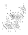
この発明の第1の実施の形態を図1から図12により説明する。この分電盤は例えば電圧極U、V、Wと中性極Nとの間に負荷を接続する3相4線式配線路に設置される。分電盤は、箱体1内に第1内器ブロック2と、第2内器ブロック3を配設している。
A first embodiment of the present invention will be described with reference to FIGS. This distribution board is installed, for example, in a three-phase four-wire wiring path that connects a load between the voltage electrodes U, V, and W and the neutral electrode N. In the distribution board, a first
箱体1は、底板6およびこの四周から立設する上下左右の側板7〜10を有する一面開口の箱体である。
The
第1内器ブロック2は、各人出力端子4、5を箱体1の上下側板7、8の方向として複数の分岐ブレーカ20を箱体1の左右側板9、10の方向に並べて基板11上に並設している。基板11は左右側板9、10の内側に沿って配設された内器側板12の底板側に設けた連結片にねじ21により取付られ、基板11は底板6から間隔をおいた位置となっている。内器側板12は箱体1の左右側板9、10の上側に係止する係止片13を開口側端部に有し、係止片13が箱体1の側板9、10にねじ14により取付けられている。
The first
基板11上には複数の2極型の分岐ブレーカ20が一列に並び、かつその並び方向の一端に主幹ブレーカ15が設置されている。分岐ブレーカ20も主幹ブレーカ15もともに並び方向の一側に入力端子4、15aが配置され、他側に出力端子5、15bが配置されている。図2に示すように、基板11の幅方向の一側に取付爪17を形成し、中間部に係止片18を切り起こし、下側に押さえ部19を設けている。分岐ブレーカ20の入力端子4側の取付凹部を取付爪17に係合し、底部の凹部に係止片18を係合し出力端子5側を押さえ部19で押さえ固定している。主幹ブレーカ15も分岐ブレーカ20と同様に基板11に取付けられている。
A plurality of two-
第2内器ブロック3は、第1の内器ブロック2と同じ構成であり、主幹ブレーカ15が設けられていない点、および主幹ブレーカ15の位置に分岐ブレーカ20が設けられている点が異なるのみである。第2内器ブロック3は第1内器ブロック2と所定の配線間隔をおいて平行に配置され、同じ内器側板12にねじ21により取付けられている。
The second
複数の第1分岐バー23〜26は、本体が細長状の導電板により形成され、第1内器ブロック2の各分岐ブレーカ20の入力端子4側で各分岐ブレーカ20の並設方向に延出し、かつ、その幅方向一方側が箱体1の底板6に対向する形として配置されている。本体には後述の主幹バー27〜30に接続される主幹接続部31と、本体から各分岐ブレーカ20側に突出して各分岐ブレーカ20の入力端子4に接続される分岐接続部32とを折曲している。各第1分岐バー23〜26は分岐ブレーカ20に近いものほど長く形成され、主幹接続部31はその主幹ブレーカ15側の端部に主幹ブレーカ15の入力端子15aから側板7の方向に折曲されて板厚方向が箱体1の底板6に向くようにし、その中心に孔31aを形成している。なお中性極の分岐バー26が分岐ブレーカ20の最も近くに配設されている。
The plurality of
複数の第2の分岐バー34〜37も、第1の分岐バー23〜26と同構成であるが、主幹ブレーカ15がない分第1の分岐バー23〜26よりも長く、分岐接続数も多い。
The plurality of second branch bars 34 to 37 have the same configuration as the first branch bars 23 to 26, but are longer than the first branch bars 23 to 26 due to the absence of the
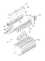
複数の主幹バー27〜30は、第1内器ブロック2の主幹ブレーカ15の位置の入力端子15a側から、第1内器ブロック2および箱体1の底板6の間を通って、第2内器ブロック3側へ突出して、各第1分岐バー23〜26と各第2分岐バー34〜37とに接続される。各主幹バー27〜30は、細長状の導電板により形成され、その厚み方向一方側が箱体1の底板6に対向する形で各分岐ブレーカ20の並設方向に並設されている。各主幹バー27〜30の中間部には主幹ブレーカ15の出力端子15bに接続される接続片40を有する。接続片40は主幹バー27〜30に立設されるように配置され、主幹バー27〜30に近い端部に連結片47を折曲するとともに連結孔46を形成し、主幹バー27〜30から遠い端部に出力端子接続部42を折曲している。接続片連結孔45とこれに整合する連結孔46にねじ41が通される。主幹バー27〜30の両端には幅方向に長孔43を形成し、中間部に位置決め孔44と接続片連結孔45を有する。長孔43にそれぞれ接続ねじ49が通される。
The plurality of
また各主幹バー27〜30は、これらを個々に隔離収納する複数の収納部51を有した絶縁部材52に支持され、その絶縁部材52が主幹ブレーカ15の位置の基板11と箱体1の底板6との間に配置されている。絶縁部材52は、両側に取付片53を突設し、取付片53を基板11の係止片18の切り起こしにより形成された穴を通して基板11の穴縁に係止し、ねじ54(図1)により固定している。絶縁部材52の各収納部51は分岐バー23〜26、34〜37間の相互間隔分、互いに長手方向に順次ずらせて各分岐バー23〜26、34〜37の主幹接続部31に対応するように配置している。主幹バー27〜30と分岐バー23〜26、34〜37の接続関係は、主幹バー27に分岐バー23、34が接続され、主幹バー28に分岐バー24、35が接続され、主幹バー29に分岐バー25、36が接続され、主幹バー30に分岐バー26、37が接続されている。すなわち、1つの分岐バーに隣接する分岐バーであって、分岐ブレーカ20の入力端子4と反対側に位置するものは、上記1つの分岐バーに接続された主幹バーに隣接する主幹バーであって、第1内器ブロック2の分岐ブレーカの並び方向の他端すなわち主幹ブレーカ15と反対側端部寄りに位置するもの、に接続される関係にある。この結果、絶縁部材52は各収納部51における各分岐バーの主幹接続部31に対応する位置を、分岐ブレーカ20に一番近い収納部51から遠い収納部51の順に箱体1の上側の側板7に近い順としている。各主幹バー27〜30が絶縁部材52に収納された状態では、主幹バー27〜30が絶縁部材52と第1内器ブロック2の間に位置する形で絶縁部材52を第1内器ブロック2に取着している。この場合、絶縁部材52の各収納部51に突起59を設け、主幹バー27〜30の位置決め孔44を突起59に嵌合して位置決めしている。
Each of the
各分岐バー23〜26、34〜37の主幹接続部31と各主幹バー27〜30とを貫通した接続ねじ49のねじ部が螺合するナット56およびねじ41が螺合するナット57は、絶縁部材52に収納されている。すなわち、図6に示すように各収納部51にナット56、57を回転不能に収納するナット収納凹所60と、このナット収納凹所60に連通してねじ部の先端が配設されるねじ遊挿凹所61とを有し、かつ箱体1の底板6側へ突出するねじ配設突部62を形成している。ナット56は螺合部となるねじ孔56aがナット中心から分岐バー長手方向の一方にずれて形成されている。その偏心量はナット56を反転したときに分岐ブレーカの入力端子4の位置の異なる例えば1極型分岐ブレーカなどの別種の分岐ブレーカの入力端子に対応することができるように決められる。ねじ配設突部62は、第1内器ブロック2に絶縁部材52を取着した状態で箱体1の底板6に当接する位置まで突出形成されている。
The
第1のカバー64は第1内器ブロック2および第2内器ブロック3の分岐バー23〜26、34〜37の相互間に差し込み被覆する。第2のカバー65は第1のカバー64に形成された爪66に対向して設けた孔67を爪66に係止して分岐バー23〜26、34〜37の露出部を被覆する。第3のカバー68は第1内器ブロック2の分岐バー23〜26の主幹接続部側端部に差し込み被覆する。第4のカバー70は分岐バー23〜26の主幹接続部31と反対側の端部を被覆し、ねじ31で基板11に固定している。第5のカバー72は主幹バー27〜30の接続片40と第2内器ブロック3の主幹接続部側端部を被覆するもので、絶縁部材52の両側に形成した爪73にカバー72に形成した孔74を係止して取付けている。絶縁板75は絶縁部材52の主幹バー27〜30と基板11の係止片18の切り起こし部分との間に介在されるもので、絶縁部材52に形成した爪76に絶縁板75の孔77を係止して固定する。
The
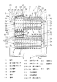
図12は分電盤の箱体1を蓋78で閉じた状態であり、蓋78を通して分岐ブレーカ20および主幹ブレーカ15のハンドルが見える透光部79を有する。
FIG. 12 shows a state in which the
この実施の形態によれば、上下の第1内器ブロック2および第2内器ブロック3の分岐ブレーカ20毎に分岐バー23〜26、34〜37を設けたので、上下どちらの分岐ブレーカ20であっても、どの電圧極でも容易に接続することができる。また、主幹バー27〜30が第1内器ブロック2の各分岐ブレーカ23〜26よりも上側から第2内器ブロック3側へ突出しているので、第1分岐バー23〜26と第2分岐バー34〜37とを主幹バー27〜30に接続し易くすることができる。さらに、主幹バー27〜30を第1内器ブロック2と箱体1の底板6との間に配設しているので、主幹バー27〜30の表面側となる基板11上にも主幹ブレーカ15や分岐ブレーカまたは他の部材を配設することができ、省スペース化が図れる。
According to this embodiment, since the branch bars 23 to 26 and 34 to 37 are provided for the
主幹ブレーカ15も第1内器ブロック2および第2内器ブロック3と内器側板12を介して一体化して配設することができ、更なる省スペース化が図れる。
The
主幹バー27〜30に対して箱体1の開口側から主幹ブレーカ15や各分岐バー23〜26を接続することができ、主幹バー27〜30への接続作業が容易となる。また、各分岐バー23〜26の幅方向を底板6に向く方向としているので、極数が多くなって分岐バーの数が増えた場合、その厚み方向に並設することで対応させることができ、省スペース化が図れる。
The
各分岐バー23〜26、34〜37を主幹バー27〜30に接続する際、各分岐バー23〜26、34〜37を複雑に折曲形成することなく、主幹接続部31が各分岐バー23〜26、34〜37の本体に交差しないようにできるので、各分岐バー23〜26、34〜37を簡単に形成でき、各分岐バー23〜26、34〜37の絶縁確保が簡単にできる。
When connecting each of the branch bars 23 to 26 and 34 to 37 to the
第1内器ブロック2、第2内器ブロック3、絶縁部材52、主幹バー27〜30を一体化することができるので、箱体1への着脱作業が容易となる。
Since the 1st
主幹バー27〜30にねじ41、49で接続される各部材を外す際、底板6に当接するねじ配設突部62により、その押圧力を箱体の底板6で吸収することができ、もって絶縁部材52が破壊され難くなる。
When removing each member connected to the
なお、主幹バー27〜30は第1内器ブロック2のみならず第2内器ブロック3の下側も通り抜ける構成が可能であり、分岐バー34〜37を第2内器ブロック3の下側に配置することも可能である。
The
1 箱体
2 第1内器ブロック
3 第2内器ブロック
4 入力端子
5 出力端子
6 底板
11 基板
15 主幹ブレーカ
20 分岐ブレーカ
23〜26 第1分岐バー
27〜30 主幹バー
31 主幹接続部
32 分岐接続部
34〜37 第2分岐バー
49 接続ねじ
51 収納部
52 絶縁部材56 ナット
60 ナット収納凹所
61 ねじ遊挿凹所
62 ねじ配設突部
DESCRIPTION OF
23-26 1st branch bar 27-30 Main bar
31
Claims (6)
前記第1分岐バーおよび前記第2分岐バーは、それぞれ細長状の導電板により形成され、幅方向が前記箱体の底板に対向し長手方向が前記第1内器ブロックおよび前記第2内器ブロックの前記分岐ブレーカの並び方向となる本体と、前記本体に設けられ前記主幹バーに接続される主幹接続部と、前記本体から前記分岐ブレーカ側に突出して前記分岐ブレーカの前記入力端子に接続される分岐接続部とを有する請求項2記載の分電盤。 The plurality of main bars are juxtaposed in the direction in which the branch breakers of the first inner block are arranged, and each is formed by an elongated conductive plate, the thickness direction of which faces the bottom plate of the box, and the longitudinal direction is Intersect the direction of the branch breakers of the first internal block,
The first branch bar and the second branch bar are each formed by an elongated conductive plate, the width direction is opposed to the bottom plate of the box, and the longitudinal direction is the first inner block and the second inner block. A main body in the direction in which the branch breakers are arranged, a main connecting portion provided on the main body and connected to the main bar, and protruding from the main body toward the branch breaker and connected to the input terminal of the branch breaker The distribution board according to claim 2, further comprising a branch connection portion.
前記複数の第1分岐バーおよび前記複数の第2分岐バーは、前記第1内器ブロックおよび前記第2内器ブロックの前記分岐ブレーカの入力端子に接近離間する方向に並設されるとともに前記主幹バーに交差し、
前記複数の第1分岐バーおよび前記複数の第2分岐バーと前記主幹バーとの接続関係において、前記複数の第1分岐バーおよび前記複数の第2分岐バーのうちの一つの分岐バーの前記入力端子と反対側に隣接する他の分岐バーは、前記一つの分岐バーが接続される一つの主幹バーの前記分岐ブレーカの並び方向の他端側に隣接する他の主幹バーと、接続される関係を有する請求項3記載の分電盤。 The plurality of main bars are arranged on one end side of the branching breakers in the first inner block in the arrangement direction,
The plurality of first branch bars and the plurality of second branch bars are juxtaposed in a direction approaching and separating from the input terminals of the branch breakers of the first internal unit block and the second internal unit block, and the main trunk Cross the bar,
The input of one of the plurality of first branch bars and the plurality of second branch bars in the connection relationship between the plurality of first branch bars and the plurality of second branch bars and the main bar. The other branch bar adjacent to the opposite side of the terminal is connected to the other main bar adjacent to the other end side of the branch breaker in the arrangement direction of the one main bar to which the one branch bar is connected. The distribution board according to claim 3.
前記複数の主幹バーは個々に隔離収納する複数の収納部を有した絶縁部材に支持され、
前記絶縁部材は前記底板と前記基板の間で前記基板に取付けられ、
前記主幹バーは前記絶縁部材と前記基板との間に配置されている請求項4記載の分電盤。 The first internal unit block has a substrate to which the branch breaker is attached at a position spaced from the bottom plate of the box.
The plurality of main bars are supported by an insulating member having a plurality of storage portions that are individually stored separately.
The insulating member is attached to the substrate between the bottom plate and the substrate;
The distribution board according to claim 4, wherein the main bar is disposed between the insulating member and the substrate.
前記絶縁部材は前記接続ねじが螺合するナットを収納するナット収納凹所を形成するとともに、前記ナット収納凹所に連通して前記接続ねじのねじ部の先端が位置するねじ遊挿凹所を形成しかつ前記箱体の底板側に突出するねじ配設突部を有し、前記ねじ配設突部は前記第1内器ブロックに前記絶縁部材を取着した状態で前記箱体の底板に当接する位置まで突出されている請求項5記載の分電盤。 The main connection part and the main bar have holes through which connection screws pass,
The insulating member forms a nut housing recess that houses a nut into which the connection screw is screwed, and a screw loose insertion recess that communicates with the nut housing recess and at which a tip of the thread portion of the connection screw is located. A screw-disposed protrusion that is formed and protrudes toward the bottom plate of the box, and the screw-disposed protrusion is formed on the bottom plate of the box with the insulating member attached to the first inner block. The distribution board according to claim 5, wherein the distribution board is projected to a contact position.
Priority Applications (2)
| Application Number | Priority Date | Filing Date | Title |
|---|---|---|---|
| JP2005089398A JP4385976B2 (en) | 2005-03-25 | 2005-03-25 | Distribution board |
| CN2006100676857A CN1838495B (en) | 2005-03-25 | 2006-03-23 | Distribution switchboard |
Applications Claiming Priority (1)
| Application Number | Priority Date | Filing Date | Title |
|---|---|---|---|
| JP2005089398A JP4385976B2 (en) | 2005-03-25 | 2005-03-25 | Distribution board |
Publications (2)
| Publication Number | Publication Date |
|---|---|
| JP2006271174A JP2006271174A (en) | 2006-10-05 |
| JP4385976B2 true JP4385976B2 (en) | 2009-12-16 |
Family
ID=37015787
Family Applications (1)
| Application Number | Title | Priority Date | Filing Date |
|---|---|---|---|
| JP2005089398A Active JP4385976B2 (en) | 2005-03-25 | 2005-03-25 | Distribution board |
Country Status (2)
| Country | Link |
|---|---|
| JP (1) | JP4385976B2 (en) |
| CN (1) | CN1838495B (en) |
Families Citing this family (4)
| Publication number | Priority date | Publication date | Assignee | Title |
|---|---|---|---|---|
| JP4830813B2 (en) * | 2006-11-27 | 2011-12-07 | パナソニック電工株式会社 | Distribution board |
| WO2009020487A1 (en) * | 2007-08-06 | 2009-02-12 | Abb Inc. | Panelboard |
| JP5552039B2 (en) * | 2010-12-21 | 2014-07-16 | パナソニックエコソリューションズ電路株式会社 | Distribution board |
| FR2987503B1 (en) * | 2012-02-28 | 2014-02-28 | Schneider Electric Ind Sas | DISTRIBUTION STATION MEDIUM VOLTAGE |
Family Cites Families (2)
| Publication number | Priority date | Publication date | Assignee | Title |
|---|---|---|---|---|
| JP4254150B2 (en) * | 2002-07-26 | 2009-04-15 | パナソニック電工株式会社 | Distribution board |
| CN1322644C (en) * | 2003-01-29 | 2007-06-20 | 第一P&P株式会社 | Distribution board |
-
2005
- 2005-03-25 JP JP2005089398A patent/JP4385976B2/en active Active
-
2006
- 2006-03-23 CN CN2006100676857A patent/CN1838495B/en not_active Expired - Fee Related
Also Published As
| Publication number | Publication date |
|---|---|
| CN1838495A (en) | 2006-09-27 |
| JP2006271174A (en) | 2006-10-05 |
| CN1838495B (en) | 2011-01-26 |
Similar Documents
| Publication | Publication Date | Title |
|---|---|---|
| EP1883132B1 (en) | Terminal block with U-shaped conducting part of connecting electric wires | |
| JP2009099405A (en) | Plug-in circuit breaker | |
| US5995362A (en) | Support and electrical power supply device for electrical switchgear | |
| JP4385976B2 (en) | Distribution board | |
| US6514093B1 (en) | Wall mounting power adapter socket | |
| RU2010105389A (en) | MODULAR CONNECTOR FOR ELECTRICAL CONNECTIONS | |
| JP5800624B2 (en) | Busbar end structure of electrical junction box | |
| US6511331B2 (en) | Electrical junction box for a vehicle | |
| JP4746512B2 (en) | Distribution board | |
| JP4389827B2 (en) | Distribution board | |
| JP3925678B2 (en) | Connection conductor device for distribution board | |
| KR100534589B1 (en) | Between main busbar and sub busbar for an distribution switchboard and connecting apparatus thereof | |
| JP4544586B2 (en) | Distribution line main bar connection structure | |
| JP5552039B2 (en) | Distribution board | |
| JP2004088899A (en) | Distribution board | |
| JP4746513B2 (en) | Distribution board | |
| KR100988788B1 (en) | Assembling type busbar | |
| JPH09270226A (en) | Circuit breaker, and distribution board equipped with it | |
| JPH0828182B2 (en) | Earth leakage circuit breaker | |
| JP3015143B2 (en) | Distribution board branching device | |
| JPH10327508A (en) | Bus-supporting stage for distribution board | |
| JP4035699B2 (en) | Distribution board | |
| JP4674930B2 (en) | Electrical junction box | |
| JP3902051B2 (en) | Power distribution box | |
| JP2002142314A (en) | Connection conductor device of panelboard |
Legal Events
| Date | Code | Title | Description |
|---|---|---|---|
| A621 | Written request for application examination |
Free format text: JAPANESE INTERMEDIATE CODE: A621 Effective date: 20071003 |
|
| A977 | Report on retrieval |
Free format text: JAPANESE INTERMEDIATE CODE: A971007 Effective date: 20090710 |
|
| A131 | Notification of reasons for refusal |
Free format text: JAPANESE INTERMEDIATE CODE: A131 Effective date: 20090714 |
|
| A521 | Written amendment |
Free format text: JAPANESE INTERMEDIATE CODE: A523 Effective date: 20090807 |
|
| TRDD | Decision of grant or rejection written | ||
| A01 | Written decision to grant a patent or to grant a registration (utility model) |
Free format text: JAPANESE INTERMEDIATE CODE: A01 Effective date: 20090908 |
|
| A01 | Written decision to grant a patent or to grant a registration (utility model) |
Free format text: JAPANESE INTERMEDIATE CODE: A01 |
|
| A61 | First payment of annual fees (during grant procedure) |
Free format text: JAPANESE INTERMEDIATE CODE: A61 Effective date: 20090921 |
|
| FPAY | Renewal fee payment (event date is renewal date of database) |
Free format text: PAYMENT UNTIL: 20121009 Year of fee payment: 3 |