JP4385451B2 - Gas sensor element - Google Patents
Gas sensor element Download PDFInfo
- Publication number
- JP4385451B2 JP4385451B2 JP28590199A JP28590199A JP4385451B2 JP 4385451 B2 JP4385451 B2 JP 4385451B2 JP 28590199 A JP28590199 A JP 28590199A JP 28590199 A JP28590199 A JP 28590199A JP 4385451 B2 JP4385451 B2 JP 4385451B2
- Authority
- JP
- Japan
- Prior art keywords
- gas
- measured
- sensor element
- oxygen
- solid electrolyte
- Prior art date
- Legal status (The legal status is an assumption and is not a legal conclusion. Google has not performed a legal analysis and makes no representation as to the accuracy of the status listed.)
- Expired - Fee Related
Links
Images


Description
【0001】
【技術分野】
本発明は,自動車等の内燃機関の排気系に設置し,排ガス中のガス成分,特にNOxガス濃度を検出する,または内燃機関の空燃比(A/F)制御系に設置する空燃比センサ,酸素ガス濃度を検出するためのセンサにおいて使用することができるガスセンサ素子に関する。
【0002】
【従来技術】
自動車の排気ガス中の有害物質(NOx,THC,CO等)による大気汚染とともに,CO2による地球温暖化が地球的な規模で現代社会に深刻な問題を引き起こしている。
大気汚染防止の法規制により,有害物質の排出低減用,排ガス浄化用の触媒コンバータの劣化検知等への要求が厳しくなっている。
一方,地球温暖化防止対策として,排出CO2の削減,燃費規制もしくは税制的な優遇措置の導入が検討されている。
これらの自動車市場動向に対して,自動車に対する社会的なニーズとして,エミッションの低下と燃費向上との両立要求がある。
【0003】
これらの要望に対し,ガソリンエンジンでは燃費向上を目的とし,リーンバーンエンジンや直墳エンジン(燃料の気筒内への直接噴射)による希薄燃焼化が進められている。
この時,希薄燃焼ということで,排出される有害物質の中でNOxの後処理が重要となり,従来の三元触媒に代わってNOx触媒を用いた排ガス浄化システムが検討されている。
また,ディーゼルエンジンにおいては電子制御化が進められ,ガソリンエンジンと同様にNOx触媒を用いたDeNOx触媒システムの開発が進められている。
上記システムにおいて,NOx触媒の浄化率制御やNOx触媒の劣化検知をより正確で効果的に行うためには,排ガス中のNOxガス濃度を直接検出可能なガスセンサを設置することが望ましい。
【0004】
そして,従来知られた排ガス中のNOxガス濃度を直接検出するためのガスセンサ素子としては,例えば特開昭64−39545号が挙げられる。
上記ガスセンサ素子は,(1)Pt電極と固体電解質体とよりなる一組の酸素ポンプセルとセンサセル,(2)Rh電極と固体電解質体とよりなるもう一組の酸素ポンプセルとセンサセルとの組み合わせを有し,導入路を介して排ガスが導かれる被測定ガス室の内外に,固体電解質体と各電極とを挟んで(1),(2)の酸素ポンプセルを配設し,また上記被測定ガス室に(1),(2)のセンサセルを配設し,それぞれの電流値の差から被測定ガス中のNOxガス濃度を測定するよう構成されている。
【0005】
または,図8に示すようなガスセンサ素子が挙げられる(特開平8−271476)。
上記ガスセンサ素子9は,固体電解質体901,902を有し,両者の間に配置したスペーサ内に形成した被測定ガス室を有する。この被測定ガス室は第1室903と第2室904を有する。
被測定ガスは導入路905を通じて第1室903に導入される。第1室903の酸素ガス濃度は酸素センサセル91により検出され,これによって検出された酸素ガス濃度が所定値となるように,第1酸素ポンプセル92の駆動電圧がフィードバック制御される。
【0006】
酸素センサセル91は固定電解質体902の表面に設けた電極911,912を大気通路907,第1室903にそれぞれ露出するよう構成されている。
第1酸素ポンプセル92は固体電解質体901とその両面の電極921,922とよりなり,電極921は被測定ガスに,電極922は第1室903に露出形成されている。
【0007】
通路906を通じて第1室903に連通する第2室904には,第2室904内の酸素ガスを排出する第2酸素ポンプセル93が設けてある。第2酸素ポンプセル93は固体電解質体902と電極911,932とで構成され,第2室904に露出する電極932はNOxに対する還元性を有する。
【0008】
第2室904では被測定ガス中のNOxが還元分解されて新たな酸素ガスが発生し,第2酸素ポンプセル93を流れるポンプ電流が増減する。
第1室903より第2室904に拡散する被測定ガス中の酸素ガス濃度は一定であることから,このポンプ電流の増減はNOxの還元に基づくものである。
つまり,これを測定することでNOxガス濃度を測定できる。
【0009】
【解決しようとする課題】
しかしながら,ガスセンサ素子においては導入路から被測定ガス室へと被測定ガスが拡散するが,この導入路はガスセンサ素子の体格の関係からピンホール状の貫通穴となるのが一般的である。また,この貫通穴は通常機械加工によって,固体電解質体となるシートに対し形成される。
【0010】
そして,上記機械加工によってシートに形成されたピンホールの導入路の拡散口径と距離では拡散するガスの拡散量は温度の1.75乗に比例することが知られており,従って,従来ガスセンサ素子において,被測定ガス室に導入される被測定ガス量,また特定ガス量は外部環境の温度に応じた値となる。
このため,出力電流に温度依存性が生じ,排ガス温度が大きく変化する場合に測定誤差が生じ易いという欠点があった。
なお,上記問題は,被測定ガス中のO2,HC,CO等の特定ガス濃度成分を測定するためのガスセンサ素子共通の問題である。
【0011】
本発明は,かかる従来の問題点に鑑みてなされたもので,被測定ガス温度が大きく変化する環境において測定誤差が生じ難い,ガスセンサ素子を提供しようとするものである。
【0012】
【課題の解決手段】
請求項1に記載の発明は,酸素イオン導電性を有する第1固体電解質体および第2固体電解質体と,
被測定ガスが導入され上記第1固体電解質体と上記第2固体電解質体とのそれぞれに対面するように構成される被測定ガス室と,
基準ガスが導入され上記第2固体電解質体と対面するように構成される基準ガス室と,
上記被測定ガス室に対面するよう配置されると共に基準ガスが導入される基準ガス室に対面するように上記第2固体電解質体に設けられ,更に被測定ガス中のNOxガス濃度を検出するよう構成された検出セルと,
上記被測定ガス室に対面するように上記第1固体電解質体に設けられると共に被測定ガス室に対し酸素ガスをポンピングするよう構成された酸素ポンプセルと,
上記被測定ガス室に被測定ガスを導入するよう構成されると共に上記酸素ポンプセルの表面に設けられた少なくとも1つのピンホールより構成された導入路とよりなるガスセンサ素子であって,
上記酸素ポンプセルは,上記ガスセンサ素子の長手方向における上記検出セルと異なる位置であって上記被測定ガスの流れの上流側に配置され,
上記酸素ポンプセルの表面はガスセンサ素子の外側に面しており,かつセンサ出力の温度依存性を低減するために上記導入路を設けた上記酸素ポンプセルの表面を覆うように平均細孔径が200〜2000Åの多孔質拡散抵抗層が設けてあることを特徴とするガスセンサ素子にある。
【0013】
本発明において最も注目すべきことは,ピンホールより構成された導入路を設けた酸素ポンプセルの表面を覆うように多孔質拡散抵抗層を設けたことにある。
上記酸素ポンプセルの表面はガスセンサ素子の外側に直接的あるいは間接的に面している。そして,ガスセンサ素子の外側は直接的あるいは間接的に被測定ガスと接している。被測定ガス室に導入される被測定ガスはガスセンサ素子の外部から多孔質拡散抵抗層を経て導入路の入口から導入され,導入路中を通過し,該導入路の出口から被測定ガス室に拡散する。
この導入路は断面形状が丸型または多角形のピンホール状の貫通穴等で構成することができ,また,その数は1つであっても複数個であってもよい。
【0014】
また,上記多孔質拡散抵抗層は酸素ポンプセルの表面だけを覆うように設けてもよいし,酸素ポンプセルを設けた固体電解質体の表面全体を覆うように設けてもよい。
また,上記多孔質拡散抵抗層の表面に,多孔質拡散抵抗層の目詰まり防止用のトラップ層を設けることができる。このものは,被測定ガス中の被毒物をトラップすることができる。また,排ガス中の未燃焼ガスを平衡化する触媒層を設けることもできる(図1参照)。
【0015】
また,上記酸素ポンプセルは,例えば固体電解質体と該固体電解質体に設けられた一対の内側ポンプ電極と外側ポンプ電極とより構成されている。
この場合,上記内側ポンプ電極は上記被測定ガス室に対面するよう配置され,上記外側ポンプ電極はガスセンサ素子の外側に配置されているため,上記導入路は上記外側ポンプ電極に設けることができる(実施形態例1参照)。
【0016】
次に,本発明の作用につき説明する。
本発明にかかるガスセンサ素子において,被測定ガスは多孔質拡散抵抗層を通過した後,導入路に入り,被測定ガス室に達する。
多孔質拡散抵抗層を通過する被測定ガスの拡散はクヌーセン拡散と分子拡散とが混じりあった拡散となるため,温度依存性が小さくなる。つまり,温度の高低にかかわらず被測定ガスの被測定ガス室に対する拡散量がほぼ一定となる。
【0017】
ところで,本発明にかかるガスセンサ素子において,上記酸素ポンプセルは被測定ガス室中の被測定ガスから酸素ガスをポンピングし,該被測定ガス室中の酸素ガス濃度を一定としたり,被測定ガス室中から酸素ガスを除去したりするために設けてある。
上記検出セルは,被測定ガス室中のNOxガスを還元するような活性を有しており,この還元作用によりNOxガスから酸素イオンが分離される。発生した酸素イオンによるイオン電流を測定することで,被測定ガス室中のNOxガスの量に応じた出力電流を得ることができる。
【0018】
本発明では被測定ガスの拡散量の温度依存性が小さくなるため,被測定ガス室には温度の高低にかかわらずほぼ一定の被測定ガスが導入されることとなる。このため,被測定ガス室中のNOxガスの量が温度の高低にかかわらず被測定ガス中のNOxガス濃度に比例する。
このため,本発明によれば,測定精度が温度に依存しないガスセンサ素子を得ることができる。
【0019】
以上,本発明によれば,被測定ガス温度が大きく変化する環境において測定誤差が生じ難い,ガスセンサ素子を提供することができる。
【0020】
また,導入路は酸素ポンプセル上に設けてあるため,該酸素ポンプセルは導入直後の被測定ガスから酸素ガスをポンピングすることができる。
よって,検出セルに被測定ガスが到着する前に酸素ガスを被測定ガスから確実にポンピングすることができ,ガスセンサ素子の出力電流から酸素ガス濃度の影響を確実に除くことができる。
【0021】
次に,請求項2に記載の発明のように,上記導入路の中心位置と上記外側ポンプ電極先端部との距離をA,上記外側ポンプ電極の長さをBとすると,両者の間にはA/B≦0.5という関係が成立することが好ましい。
これにより,酸素ポンプセルの酸素ガス排出作用を充分得ることができる。即ち,NOxガスがないときのオフセット電流の安定化を図ることができる。
【0022】
上記A/Bが0.5より大である場合には,酸素ポンプセルで酸素ガスが充分排出できないまま検出セルに酸素ガスが第2拡散通路等を通じて拡散し,検出セルで残留酸素ガスによる電流が流れるため,NOxガスがないときのオフセット電流がばらつき,出力に酸素ガス濃度依存性が生じるおそれがある。
また,上記A/Bは0であってもよい。0の場合は,丁度外側ポンプ電極先端部に重なるように導入路が設けてある場合である。
【0023】
なお,上記外側ポンプ電極先端部とは,図3の符号219に示すごとく,ガスセンサ素子において検出セルを設けた位置と反対側の外側ポンプ電極の端部である。
また,上記導入路の中心位置とは該導入路の入口形状における中心または重心であり,導入路が複数個存在する場合には,上記ポンプ電極の先端部から最も遠い導入路の中心位置を本請求項における中心位置として採用する。
上記外側ポンプ電極長さとは,外側ポンプ電極の一方の端部から他方の端部までの長さである。
【0024】
次に,上記導入路の総断面積は0.02〜0.8mm2であることが好ましい。
これにより,適正なセンサの出力電流を得ることができる。
総断面積が0.02mm2未満の場合には,導入路の径が小さすぎて,ガスセンサ素子製造において安定して導入路を形成することができなくなることと,センサの電流値が小さすぎてノイズ等の影響を受けるおそれがある。
【0025】
0.8mm2より大である場合には,導入路を通って被測定ガス室に流入する被測定ガスの量が多く,酸素ポンプセルで充分に酸素ガスをポンピングすることができず,検出セルから得られる出力電流が正しくNOxガス濃度を反映せず,酸素ガス濃度に対する依存性が生じるおそれがある。
【0026】
次に,上記導入路は機械加工により形成されていることが好ましい。
これにより,製造が簡易でかつセンサの電流値が安定したガスセンサ素子を得ることができる。
【0027】
次に,上記多孔質拡散抵抗層の厚みは0.05〜0.3mmであることが好ましい。
これにより,ガスセンサ素子製造の際の焼成工程で多孔質拡散抵抗層の割れ防止を図ることができ,またガスセンサ素子のセンサ特性の安定化を図ることができる。
【0028】
仮に厚みが0.05mm未満である場合には,焼成工程での多孔質拡散抵抗層の割れや温度依存性の悪化が生じるおそれがある。また,厚みが0.3mmより厚い場合には,被測定ガスの導入路の長さが長くなりすぎて,応答性の悪化とセンサ出力の低下を招くおそれがある。
【0029】
次に,上記多孔質拡散抵抗層の平均細孔径は200〜2000Åである。
これにより,センサ特性の安定化を図ることができる。
【0030】
仮に平均細孔径が200Å未満である場合には,多孔質拡散抵抗層の細孔の孔径が小さすぎてガス拡散が妨げられるおそれがある。また,被測定ガス拡散が妨げられ,通過時間がかかりすぎるため,応答性の悪化とセンサ出力の低下を招くおそれがある。また,2000Åより大である場合には,被測定ガスの拡散状態が安定しないため,温度依存性の悪化が生じるおそれがある。また,被測定ガスの導入量が増えて出力に酸素ガス濃度依存性が生じるおそれがある。
【0031】
次に,請求項3の発明のように,上記多孔質拡散抵抗層の気孔率は3〜20%であることが好ましい。
これにより,安定したセンサ特性を得ることができる。
仮に気孔率が3%未満である場合には,被測定ガスの拡散がスムーズに行われないため,応答性の悪化と出力の低下を招くおそれがある。また,気孔率が20%より大である場合には,ガスセンサ素子製造の際の焼成工程において多孔質拡散抵抗層の割れが発生するおそれがある。また,センサ出力の温度依存性の悪化を生じるおそれがある。また,被測定ガスの導入量が増えて出力に酸素ガス濃度依存性が生じるおそれがある。
【0032】
次に,上記被測定ガス室は第1固体電解質体及び第2固体電解質体のそれぞれに対面するように構成され,また上記基準ガス室は第2固体電解質体と対面するように構成され,上記酸素ポンプセルは第1固体電解質体に,上記検出セルは第2固体電解質体にそれぞれ設けてある。
これにより,酸素ポンプセルと検出セルとに流れる電流の干渉を防止することができ,より正確なガス濃度の測定を行うことができる。
【0033】
次に,請求項4記載の発明のように,上記導入路による拡散抵抗をD1,上記多孔質拡散抵抗層による拡散抵抗をD2とすると,両者の比は0.5≦D2/(D1+D2)≦0.9であることが好ましい。
【0034】
これによりセンサ出力の安定化を図ることができる。
D2/(D1+D2)が0.5未満である場合には,ポンプセル上の導入路による拡散抵抗,すなわち分子拡散が支配的となり温度依存性が悪化するおそれがある。
D2/(D1+D2)が0.9より大である場合には,多孔質拡散抵抗層での拡散が支配的となり,応答性が悪化するおそれがある。
【0035】
D1,D2は上記二つの拡散抵抗が,内部空間で形成された拡散抵抗より充分大きい場合,以下のように表される。
Is=(D1+D2)ln{(1−PNOx)/P}
ここにIsはセンサ出力,PNOxはNOxの分圧,Pは全圧である。
この時,D1,D2はそれらの幾何学形状により求まるが,センサを作成して電流値を測定することで間接的に求めることができる。
具体的には多孔質拡散層を設ける前のものと,設けたものとのセンサ電流値の違いから求めることができる。
【0036】
【発明の実施の形態】
実施形態例1
本発明の実施形態例にかかるガスセンサ素子につき,図1〜図4を用いて説明する。なお,本例にかかるガスセンサ素子は内燃機関の排気系に設置され,排ガス中のNOxガス濃度を測定するガスセンサにおいて使用される。
【0037】
図1に示すごとく,本例のガスセンサ素子1は,被測定ガス室15と検出セル3と酸素ポンプセル2と導入路100とよりなる。
上記被測定ガス室15は被測定ガスが導入される。
上記検出セル3は,上記被測定ガス室15に対面するよう配置されると共に基準ガスが導入される基準ガス室16に対面するように配置され,更に被測定ガス中のNOxガス濃度を検出するよう構成されている。
上記酸素ポンプセル2は,上記被測定ガス室15に対面するよう配置され,被測定ガス室15に対し酸素ガスをポンピングするよう構成されている。
また,上記導入路100は被測定ガス室15に被測定ガスを導入するよう構成されると共に上記酸素ポンプセル2の表面に設けてある。
【0038】
そして,上記酸素ポンプセル2の表面はガスセンサ素子1の外側に面しており,かつ上記導入路100を設けた上記酸素ポンプセル2の表面を覆うように多孔質拡散抵抗層10が設けてある。
上記多孔質拡散抵抗層10の厚みは0.1mmで,平均細孔径が1100Å,気孔率が12%であるアルミナセラミックより構成されている。また,図2に示すごとく,上記導入路100はただ一つ設けてあり,その断面積は0.125mm2である。また,D2/(D1+D2)の値は0.7である。
【0039】
以下,詳細に説明する。
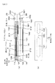
本例のガスセンサ素子1は,図1(a)に示すごとく,第1固体電解質体11,被測定ガス室用スペーサ12,第2固体電解質体13,基準ガス室用スペーサ14及びヒータ19が積層一体化されてなる。
上記第1及び第2固体電解質体11,13は酸素イオン導電性の部分安定化ジルコニアよりなる。スペーサ12,14は絶縁性のアルミナセラミックよりなる。
そして,本例のガスセンサ素子1は,酸素ポンプセル2と検出セル3の二つのセルを持った構造である。
【0040】
上記酸素ポンプセル2は,上記第1固体電解質体11とここに設けられた一対の内側ポンプ電極212及び外側ポンプ電極211より構成され,上記内側ポンプ電極212は被測定ガス室15に対面するよう配置され,上記外側ポンプ電極211はガスセンサ素子1の外側に配置される。
【0041】
上記外側及び内側ポンプ電極211,212と上記第1固体電解質体11とを貫通するようピンホールが設けられ,該ピンホールにより導入路100が構成される。この導入路100の入口101は外側ポンプ電極211に対し開口している。
図2に示すごとく,上記導入路100の入口101と上記外側ポンプ電極211,また第1固体電解質体11の表面の一部は多孔質拡散抵抗層10で覆われている。また,多孔質拡散抵抗層10の表面は被測定ガス中の被毒物よりこれを保護するためのトラップ層199で覆われている。
上記内側ポンプ電極212はPt−Au電極である。外側ポンプ電極211はPt電極である。
【0042】
上記被測定ガス室15は図1(b)に示すごとく,酸素ポンプセル2と対面する第1室151と検出セル3と対面する第2室152とに別れており,両者は拡散通路150で相互に被測定ガスが行き来可能に接続されている。
【0043】
図1(a)に示すごとく,上記検出セル3は第2固体電解質体13とここに設けられた一対の測定電極311と基準電極312とよりなり,上記測定電極311は被測定ガス室15に対面するよう配置され,上記基準電極312は第2固体電解質体13と対面するよう設けられた基準ガス室16に対面するよう配置されている
上記測定電極311及び基準電極312はPt電極である。
【0044】
上記第2基準ガス室16と対面するようにヒータ19が設けてある。
上記ヒータ19はヒータ基板191とここに設けられた発熱部190及びリード部と,これら三者を被覆する被覆基板192よりなる。
上記ヒータ基板191,被覆基板192はアルミナよりなる。
【0045】
また,図3に示すごとく,本例のガスセンサ素子1において,外側ポンプ電極211の先端部219と導入路100の中心位置109との距離A=1mm,外側ポンプ電極211の長さB=10mmであった。よって,A/Bの値は,0.1であった。
【0046】
図1(a)に示すごとく,上記外側及び内側ポンプ電極211,212と導通するよう構成され,図示を略したリード部,端子部が固体電解質体11等に設けてある。これらのリード部や端子部を通じて酸素ポンプセル2の駆動に必要な電力が酸素ポンプセル回路29を通じて電源291から供給される。また,酸素ポンプセル回路29には電流計292が接続されている。
【0047】
また,上記測定電極311及び基準電極312と導通するよう構成され,図示を略したリード部,端子部が固体電解質体13等に設けてある。これらのリード部や端子部を通じて検出セルに検出回路39が接続されている。
この検出回路39には検出セル3に電圧を印可する電源391と検出回路39を流れる電流を測定する電流計392が接続されている。
【0048】
次に,上記ガスセンサ素子1の製造方法について説明する。
第1固体電解質体11,第2固体電解質体13を構成するZrO2シート用生シートについて説明する。
6wt%のY2O3と94wt%ZrO2とよりなる平均粒径0.5μmのY2O3部分安定化ZrO2:100部(重量部,以下略),
α−Al2O3:1部,
PVB(ポリビニルブチラール):5部,
DBP(ジブチルフタレート):10部,
エタノール:10部,
トルエン:10部,
以上の材料よりなるセラミック混合物を準備し,該セラミック混合物をボールミル中で混合し,スラリーとなす。このスラリーをドクターブレード法にて乾燥厚みが0.2mmとなるように成形し,シート成形体を得た。
【0049】
第1固体電解質体用生シートは次のようにして作成した。
上記シート成形体を5×80mmの長方形に切断し,一対の外側及び内側ポンプ電極211,212と図示を略したリード部,端子部との導通用のスルーホールを設けた。
次に,内側ポンプ電極212用の印刷部を1〜10wt%Au添加Ptペーストを用いてスクリーン印刷により作成した。また,外側ポンプ電極211と図示を略したリード部,端子部用のPtペーストよりなる印刷部をスクリーン印刷により作成した。
その後,上記印刷部を貫通するように導入路100用のパンチングマシン等を用いて直径が0.5mm(断面積0.2mm2)のピンホールを設けた。
以下,生シートは焼成で20%収縮するため,完成品寸法では導入路100の直径は0.4mm(断面積0.125mm2)となる。
【0050】
第2固体電解質体用生シートは次のようにして作成した。
上記シート成形体を5×80mmの長方形に切断し,一対の測定電極311及び基準電極312と図示を略したリード部,端子部との導通用のスルーホールを設けた。
次に,測定電極311,基準電極312,図示を略したリード部,端子部用の印刷部を,Ptペーストを用いスクリーン印刷で形成した。
【0051】
次に,被測定ガス室用スペーサ12,基準ガス室用スペーサ14,ヒータ基板191,被覆基板192用生シートについて説明する。
平均粒子径0.3μmのα−Al2O3:98部,
6wt%のY2O3と94wt%ZrO2とよりなるY2O3部分安定化ZrO2:3部,
PVB(ポリビニルブチラール):10部,
DBP(ジブチルフタレート):10部,
エタノール:30部,
トルエン:30部,
以上の材料よりなるセラミック混合物を準備し,上記セラミック混合物をボールミル中で混合し,スラリーとなす。このスラリーをドクターブレード法にて乾燥厚みが0.2〜1mmとなるように成形し,シート成形体を得た。
【0052】
上記シート成形体を5×80mmの長方形に切断し,先端が閉じたコの字となるように2×75mmの窓を設けた。これが基準ガス室用スペーサ14用生シートとなる。
また,上記シート成形体を5×80mmの長方形に切断し,図1(b)に示すごとき,二つの楕円状の穴を細穴で接続したような窓を設けた。これが被測定ガス室用スペーサ12用生シートとなる。
【0053】
上記シート成形体を5×80mmの長方形に切断し,90wt%Ptと10wt%のAl2O3よりなる導電性ペーストを用いて,発熱部190及びリード部用の印刷部を形成した。これがヒータ基板191用生シートとなる。
また,上記シート成形体を5×80mmの長方形に切断した。これが被覆基板192用生シートとなる。
【0054】
次に多孔質拡散抵抗層10用の生シートについて説明する。
平均粒子径0.5μmのα−Al2O3:98部,
6wt%のY2O3と94wt%ZrO2とよりなるY2O3部分安定化ZrO2:3部,
PVB(ポリビニルブチラール):10部,
DBP(ジブチルフタレート):10部,
エタノール:30部,
トルエン:30部,
以上の材料よりなるセラミック混合物を準備し,上記セラミック混合物をボールミル中で混合し,スラリーとなす。このスラリーをドクターブレード法にて乾燥厚みが0.12mmとなるように成形し,シート成形体を得た。
上記シート成形体を5×30mmの長方形に切断し,多孔質拡散抵抗層10用の生シートとした。
【0055】
そして,上述した各生シートを常温にて感圧接着性を有するペーストを用いて,図1に示すように順次積層圧着し,積層体を形成した。この積層体を大気中1500℃にて1時間で焼成,焼成体を得た。
その後,焼成体における多孔質拡散抵抗層に対し,Al2O3:50部,無機バインダー:10部,水:40部からなるスラリーをディッピングし,乾燥した。その後,500℃,1時間で焼きつけ,トラップ層199を形成した。
以上により,本例にかかるガスセンサ素子を得た。
【0056】
次に,本例にかかるガスセンサ素子による被測定ガス中のNOxガス濃度検出について説明する。
トラップ層199,多孔質拡散抵抗層10を経て入口101より導入路100を通過して,被測定ガスが被測定ガス室15の第1室151に導入される。
上記酸素ポンプセル2は,酸素ポンプセル回路29を通じて電源291から電圧が印可されている。そして,上記内側ポンプ電極212はNOxガスに対してほぼ不活性なPt−Au電極よりなる。
よって,酸素ポンプセル2は第1室151中の酸素ガスを印加電圧に応じた分量,ポンピングしてガスセンサ素子1外へ放出する。
【0057】
この時の印可電圧は,NOxの分解が殆ど生じず,かつ酸素ガスを可能な限り被測定ガス室15から排出できるような値に調整されている。
なお,この調整は,ある特定の電圧を印可することにより,酸素ポンプセル2を流れた電流の大小により制御回路等を利用して予め計算しておく。
以上により,第1室151から酸素ガスが殆ど含まれていない状態となった被測定ガスが拡散通路150を通じて第2室152に拡散する。
また,この時に酸素ポンプセル回路29を流れる電流を電流計292より測定する。この電流計の値はポンピングされた酸素ガス量に比例するため,この値から被測定ガス中の酸素ガス濃度を測定することができる。
【0058】
そして,検出セル3における測定電極311はNOxに対して活性なPt電極である。検出セル3は電源391により電圧が印加されており,よって測定電極311はNOxを窒素イオンと酸素イオンとに分解する。
分解により生じた酸素イオンはイオン電流となって,第2固体電解質体13を経由して基準ガス室16側にポンピングされる。このイオン電流は検出セル3に接続された検出回路39上の電流計392により測定される。
この電流値から被測定ガス中のNOxガス濃度を測定することができる。
【0059】
本例の作用効果について説明する。
本例のガスセンサ素子1は,導入路100の入口101が多孔質拡散抵抗層10で覆われている。
多孔質拡散抵抗層10を通過する被測定ガスの拡散はクヌーセン拡散と分子拡散とが混じりあった拡散となるため,温度依存性が小さくなる。つまり,温度の高低にかかわらず被測定ガスの被測定ガス室15に対する拡散量がほぼ一定となる。
【0060】
本例では被測定ガスの拡散量の温度依存性が小さくなるため,被測定ガス室15には温度の高低にかかわらずほぼ一定の被測定ガスが導入されることとなる。このため,被測定ガス室15中のNOxガスの量が温度の高低にかかわらず被測定ガス中のNOxガス濃度に比例する。
よって,測定精度が温度に依存しないガスセンサ素子1を得ることができる。
【0061】
以上,本例によれば,被測定ガス温度が大きく変化する環境において測定誤差が生じ難い,ガスセンサ素子を提供することができる。
【0062】
また,本例のガスセンサ素子1は,中心位置109と先端部219との距離A,外側ポンプ電極211の長さBとの間にA/B≦0.5という関係が成立する。
このため,NOxがないときのセンサ電流であるオフセット電流の安定化を図ることができる。
【0063】
なお,本例のガスセンサ素子において被測定ガス室は第1室と第2室より構成されていたが,図4に示すごとく,ただ一つの室よりなる被測定ガス室17を持つこともできる。
【0064】
実施形態例2
本例は,実施形態例1に示すごとき本発明にかかるガスセンサ素子の性能を他の試料と共に比較説明するものである。
試料1〜5,8〜17にかかるガスセンサ素子は,実施形態例1に記載したものと同様の構造である。そして表1に示すごとき多孔質拡散抵抗層や導入路を有する。
【0065】
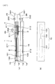
また,試料6にかかるガスセンサ素子は,図5に示すごとく,多孔質拡散抵抗層を持たず,その他の部分の構造は実施形態例1にかかるガスセンサ素子と同様である。
また,試料7にかかるガスセンサ素子は,図6に示すごとく,第1室851,第2室852,拡散通路850よりなる被測定ガス室85内が多孔質体にて充填された構造である。また,導入路100の入口101にはなにも設けられてない。それ以外は実施形態例1と同様の構造である。
【0066】
以上にかかる各試料のガスセンサ素子の性能を次のように測定した。
(1)温度依存性;
N2ガスをベースとしてNOガス(=NOxの一種)を濃度1000ppmで含むモデルガスを準備した。
このモデルガスを予め所定の流量(トータルで1リットル/分)流した状態で,各試料にかかる素子の出力電流を,各素子の検出セルに対し0.5V一定となる定電圧を定電圧電源を用いて印加して,検出セルに接続された電流計から出力電流を測定した。
【0067】
この時,素子の電極中心の温度を800±20℃で変化させ,最大出力と最小出力とを測定した。なお,この温度制御は素子と一体化されたヒータへの投入電流を制御することにより行なった。
最大出力と最小出力の差が±10%未満である場合を○,±10%以上である場合を×として,結果を表1に記載した。
【0068】
(2)焼成割れ;
次に,ガスセンサ素子を作成する際の焼成において,割れが生じたか否かについて,素子焼成後の多孔質拡散抵抗層及びその近傍の固体電解質体におけるクラックチェックをカラーチェックで行った。
その結果,クラックの発生率が1%以下である場合を○,それ以上である場合を×として,結果を表1に記載した。
【0069】
(3)出力電流;
次に,ガスセンサ素子の出力電流を温度依存性測定と同様にガス流量を調整して測定した。
その結果,被測定ガスとして1000ppmのNOxガスを含んだガスを使用した場合の出力電流と,被測定ガス中にNOxガスが含まれていない場合の出力電流をとを測定し,その差が1μAより大である場合を○,それ以下である場合を×として表1に記載した。
【0070】
(4)酸素ガス濃度依存性;
次に,ガスセンサ素子の出力電流の酸素ガス濃度依存性について,上記モデルガスの酸素ガス濃度を1〜20%の範囲で変化させて測定した。
モデルガスのNO濃度は1000ppmとなるよう流量が調整され,ポンプセルへの印加電圧はマップ制御用の回路計を用いて制御した。なお,上記マップ制御は予めポンプセルに流れる電流を測定し,それに応じた電圧を印加することを可能にする。また,ガスセンサ素子に対する印加電圧は0.5V一定である。
また,出力電流は電流計で測定した。
【0071】
その結果,被測定ガス中の酸素ガス濃度が1%〜20%の間で変化した場合,出力電流のばらつきが±10%未満である場合を○,±10%以上である場合を×として表1に記載した。
【0072】
(5)応答性;
次に,ガスセンサ素子の応答性を次のようにして測定した。
モデルガスにおいてNO濃度を1000ppmから100ppmへと変化させた時,測定される出力電流がNO濃度が1000ppmの際の60%まで低下するまでの時間を測定した。
この時間が1s未満である場合を○,1s以上である場合を×として表1に記載した。
【0073】
同表によれば,実施形態例1にかかる構造を持ったガスセンサ素子,つまり
ガスセンサ素子の外側に面した導入路の入口が多孔質拡散抵抗層で覆われているものについては,温度依存性について○であった。つまり,出力電流が温度によって殆ど変わらないことが分かった。
一方,試料6にかかる多孔質拡散抵抗層を持たないガスセンサ素子は,温度と共に出力電流が大きく変化することが分かった。
【0074】
また,多孔質拡散抵抗層を被測定ガス室内に設けた試料7のガスセンサ素子は,温度依存性については試料1〜試料5等と同様の結果を得たが,ガスセンサ素子を作成する際の焼成において,固体電解質体にクラックが発生してしまうことが分かった。これは,アルミナよりなる多孔質拡散抵抗層とジルコニアよりなる固体電解質体との熱膨張率の違いが原因である。
また,試料7は,被測定ガス室85内が多孔質拡散抵抗層にて充填され,被測定ガスの拡散が妨げらるため,センサ出力も小さかった。
センサ出力が小さい場合,例えば車に搭載して使用する際にはノイズ等による誤差でセンサ素子の検出精度が悪くなるおそれがあり,実用に耐えないことがある。
【0075】
また,表1より知れるごとく,試料10,試料11,試料12,試料14,試料16は導入路にかかるA/Bの値,導入路の断面積,抵抗層の厚み,平均細孔径及び気孔率について好ましい条件を満たしており,出力の温度依存性が小さい以外にも,焼成割れが生じず,センサ出力も大きく,出力の酸素ガス濃度依存性が小さく,更に応答性も早い,優れたガスセンサ素子である。
【0076】
試料8は,多孔質拡散抵抗層が厚く,被測定ガスの拡散が遅れるため,応答性が低かった。
試料9は,A/Bが大きく,ポンプセルで酸素ガスを充分排出する前に検出セルに被測定ガスが到着してしまうため,酸素ガス濃度の変動により出力電流が変動することが分かった。そのため,酸素ガス濃度が大きくなった場合の測定精度が低下するおそれがあった。
試料13は導入路の断面積が大きく,大量の被測定ガスが導入されるため,酸素ポンプセルによる酸素ガスの排出が不充分となりやすく,出力に酸素ガス濃度依存性が生じた。
試料15は多孔質拡散抵抗層の気孔率と平均細孔径が小さく,充分な被測定ガスが取り込めず,出力や応答性が低い。
また,試料17は多孔質拡散抵抗層の気孔率と平均細孔径が大きく,被測定ガスが大量に取り込まれやすく,酸素ポンプセルによる酸素ガスの排出が不充分となりやすく,出力に酸素ガス濃度依存性が生じた。
【0077】
【表1】

実施形態例3
本例は酸素ポンプセルと検出セルの他に,酸素センサセルを設けたガスセンサ素子について説明する。
【0079】
図7に示すごとく,本例のガスセンサ素子1は,被測定ガス室15と,該被測定ガス室15に被測定ガスを導入するよう構成された導入路100と,検出セル3と,酸素ポンプセル2とよりなる。また,被測定ガス室15の酸素ガス濃度が測定可能となるよう構成された酸素センサセル4が設けてある。
また,上記導入路100の入口101は多孔質拡散抵抗層10で覆われている。
【0080】
以下,詳細に説明する。
本例のガスセンサ素子は,第1固体電解質体11,被測定ガス室用スペーサ12,第2固体電解質体13,基準ガス室用スペーサ14及びヒータ19が積層一体化されてなる。
【0081】
上記酸素ポンプセル2は,第1固体電解質体11と内側ポンプ電極212及び外側ポンプ電極211とより構成され,内側ポンプ電極212は被測定ガス室15の第1室151に対面するよう配置され,外側ポンプ電極211はガスセンサ素子1の外側に配置される。
【0082】
上記検出セル3は第2固体電解質体13と一対の測定電極311と基準電極312とよりなり,上記測定電極311は被測定ガス室15の第2室152に対面するよう配置され,上記基準電極312は第2固体電解質体13と対面するよう設けられた基準ガス室16に対面するよう配置されている
また,上記第2基準ガス室16と対面するようにヒータ19が設けてある。
【0083】
上記酸素センサセル4は,第2固体電解質体13と,該第2固体電解質体13に設けられた電極411と,上記検出セル3を構成する測定電極311とよりなる。また,上記電極411は第2室152を挟んで対面する位置にある。
【0084】
上記外側及び内側ポンプ電極211,212と導通するよう構成され,図示を略したリード部,端子部が固体電解質体11等に設けてある。これらのリード部や端子部を通じて酸素ポンプセル2は,電源291,電流計292を持った回路29に接続される。
【0085】
また,上記測定電極及び基準電極311,312と導通するよう構成され,図示を略したリード部,端子部が固体電解質体13等に設けてある。これらのリード部や端子部を通じて検出セルは,電源391,電流計392を持った回路39に接続される。
そして,上記酸素センサセル4も,図示を略したリード部や端子部等を通じて,回路49に接続され,この回路49には電圧計492が接続されている。
【0086】
本例にかかるガスセンサ素子1では,酸素ポンプセル2により第1室151の酸素ガスのポンピングし,また,検出セル3によりNOxガス濃度を検出する。そして,上記酸素ポンプセル2のポンピングにより正確に酸素ガスが排出されるように,回路49の電圧計492で電極411と電極311との間の電圧を測定する。この電圧は,ネルンストの式に基づいた起電力が発生し,よって第2室152の酸素ガス濃度に比例する。
【0087】
よって,適当なフィードバック制御回路を回路49と回路29との間に設けて,確実に酸素ガスのポンピングが行われるように回路29の電源291を制御する。
これにより,本例のガスセンサ素子によればより精密なNOxガス濃度の測定が可能となる。
その他は,実施形態例1と同様の作用効果を有する。
【図面の簡単な説明】
【図1】実施形態例1における,(a)ガスセンサ素子の要部断面説明図(図2におけるA−A矢視断面図),(b)ガスセンサ素子における被測定ガス室の構造を示す説明図。
【図2】実施形態例1における,ガスセンサ素子の平面図。
【図3】実施形態例1における,ガスセンサ素子における,導入路の中心位置と外側ポンプ電極先端部との距離A,外側ポンプ電極の長さB,導入路の中心位置と測定電極先端部との距離Lを示す説明図。
【図4】実施形態例1における,被測定ガス室がただ一つの空間よりなるガスセンサ素子の説明図。
【図5】実施形態例2における,試料6にかかる多孔質拡散抵抗層を持たないガスセンサ素子の(a)断面説明図,(b)平面図。
【図6】実施形態例2における,試料7にかかる被測定ガス室が多孔質体により充填されてなるガスセンサ素子の(a)断面説明図,(b)平面図。
【図7】実施形態例3における,酸素センサセルを持ったガスセンサ素子の(a)断面説明図,(b)平面図。
【図8】従来技術にかかるガスセンサ素子の(a)平面図,(b)断面説明図。
【符号の説明】
1...ガスセンサ素子,
10...多孔質拡散抵抗層,
100...導入路,
101...入口,
2...酸素ポンプセル,
3...検出セル,[0001]
【Technical field】
The present invention is an air-fuel ratio sensor that is installed in an exhaust system of an internal combustion engine such as an automobile and detects a gas component in exhaust gas, particularly NOx gas concentration, or is installed in an air-fuel ratio (A / F) control system of the internal combustion engine, The present invention relates to a gas sensor element that can be used in a sensor for detecting an oxygen gas concentration.
[0002]
[Prior art]
In addition to air pollution caused by harmful substances (NOx, THC, CO, etc.) in automobile exhaust gas, CO2The global warming caused by this is causing serious problems for modern society on a global scale.
Due to laws and regulations for preventing air pollution, there are strict requirements for detecting deterioration of catalytic converters for reducing emissions of hazardous substances and purifying exhaust gases.
On the other hand, as a global warming prevention measure, emissions CO2Reduction of fuel consumption, introduction of fuel economy regulations or tax incentives are being considered.
In response to these trends in the automobile market, there is a demand for both reduction in emissions and improvement in fuel efficiency as a social need for automobiles.
[0003]
In response to these demands, gasoline engines are being used for lean combustion with lean burn engines and direct engines (direct injection of fuel into cylinders) for the purpose of improving fuel economy.
At this time, because of lean combustion, post-treatment of NOx is important among exhausted harmful substances, and exhaust gas purification systems using NOx catalysts instead of conventional three-way catalysts are being studied.
In addition, the diesel engine is being electronically controlled, and a DeNOx catalyst system using a NOx catalyst is being developed in the same manner as a gasoline engine.
In the above system, it is desirable to install a gas sensor capable of directly detecting the NOx gas concentration in the exhaust gas in order to perform the purification rate control of the NOx catalyst and the deterioration detection of the NOx catalyst more accurately and effectively.
[0004]
A conventionally known gas sensor element for directly detecting the NOx gas concentration in the exhaust gas is, for example, JP-A-64-39545.
The gas sensor element has (1) one set of oxygen pump cell and sensor cell composed of Pt electrode and solid electrolyte body, and (2) another set of oxygen pump cell and sensor cell composed of Rh electrode and solid electrolyte body. The oxygen pump cells (1) and (2) are disposed inside and outside the gas chamber to be measured, through which the exhaust gas is guided through the introduction path, with the solid electrolyte body and each electrode sandwiched therebetween, and the gas chamber to be measured The sensor cells of (1) and (2) are arranged in this manner, and the NOx gas concentration in the gas to be measured is measured from the difference between the current values.
[0005]
Another example is a gas sensor element as shown in FIG. 8 (Japanese Patent Laid-Open No. 8-271476).
The gas sensor element 9 has
The gas to be measured is introduced into the
[0006]
The
The first
[0007]
A second
[0008]
In the
Since the oxygen gas concentration in the gas to be measured diffused from the
That is, the NOx gas concentration can be measured by measuring this.
[0009]
[Problems to be solved]
However, in the gas sensor element, the gas to be measured diffuses from the introduction path to the gas chamber to be measured. This introduction path is generally a pinhole-like through hole due to the physique of the gas sensor element. In addition, the through hole is usually formed in a sheet that becomes a solid electrolyte body by machining.
[0010]
It is known that the diffusion amount of the diffused gas is proportional to the 1.75th power of the temperature in the diffusion hole diameter and distance of the introduction path of the pinhole formed in the sheet by the above machining, and thus the conventional gas sensor element. , The amount of gas to be measured introduced into the gas chamber to be measured and the specific gas amount are values corresponding to the temperature of the external environment.
For this reason, the output current is dependent on temperature, and there is a drawback that measurement errors are likely to occur when the exhaust gas temperature changes greatly.
The above problem is caused by O in the measured gas.2This is a problem common to gas sensor elements for measuring specific gas concentration components such as HC, CO, and the like.
[0011]
The present invention has been made in view of such conventional problems, and an object of the present invention is to provide a gas sensor element in which measurement errors are unlikely to occur in an environment where the temperature of a gas to be measured varies greatly.
[0012]
[Means for solving problems]
The invention described in claim 1A first solid electrolyte body and a second solid electrolyte body having oxygen ion conductivity;
The gas to be measured is introducedThe first solid electrolyte body and the second solid electrolyte body are configured to face each other.A gas chamber to be measured;
A reference gas chamber in which a reference gas is introduced and configured to face the second solid electrolyte body;
Arranged so as to face the gas chamber to be measured and so as to face the reference gas chamber into which the reference gas is introducedProvided in the second solid electrolyte body.In addition, in the gas to be measuredNOxA detection cell configured to detect gas concentration;
To face the measured gas chamberProvided in the first solid electrolyte bodyAnd an oxygen pump cell configured to pump oxygen gas to the gas chamber to be measured,
A gas sensor element configured to introduce a gas to be measured into the gas chamber to be measured and including an introduction path configured by at least one pinhole provided on a surface of the oxygen pump cell;
The oxygen pump cell is disposed at a position different from the detection cell in the longitudinal direction of the gas sensor element and upstream of the flow of the gas to be measured,
The surface of the oxygen pump cell faces the outside of the gas sensor element, andTo reduce temperature dependence of sensor outputTo cover the surface of the oxygen pump cell provided with the introduction pathThe average pore size is 200-2000 mmA porous gas diffusion resistance layer is provided in a gas sensor element.
[0013]
The most notable point in the present invention is that a porous diffusion resistance layer is provided so as to cover the surface of an oxygen pump cell provided with an introduction path composed of pinholes.
The surface of the oxygen pump cell faces the outside of the gas sensor element directly or indirectly. The outside of the gas sensor element is in contact with the gas to be measured directly or indirectly. The measured gas introduced into the measured gas chamber is introduced from the outside of the gas sensor element through the porous diffusion resistance layer through the inlet of the introduction path, passes through the introduction path, and enters the measured gas chamber from the outlet of the introduction path. Spread.
This introduction path can be constituted by a pinhole-shaped through hole or the like having a round or polygonal cross-sectional shape, and the number thereof can be one or plural.
[0014]
Further, the porous diffusion resistance layer may be provided so as to cover only the surface of the oxygen pump cell, or may be provided so as to cover the entire surface of the solid electrolyte body provided with the oxygen pump cell.
Further, a trap layer for preventing clogging of the porous diffusion resistance layer can be provided on the surface of the porous diffusion resistance layer. This can trap poisonous substances in the measured gas. A catalyst layer for equilibrating unburned gas in the exhaust gas can also be provided (see FIG. 1).
[0015]
The oxygen pump cell includes, for example, a solid electrolyte body and a pair of inner pump electrode and outer pump electrode provided on the solid electrolyte body.
In this case, since the inner pump electrode is disposed to face the gas chamber to be measured and the outer pump electrode is disposed outside the gas sensor element, the introduction path can be provided in the outer pump electrode ( Refer to Embodiment Example 1).
[0016]
Next, the operation of the present invention will be described.
In the gas sensor element according to the present invention, the measurement gas passes through the porous diffusion resistance layer, enters the introduction path, and reaches the measurement gas chamber.
Since the diffusion of the gas to be measured passing through the porous diffusion resistance layer is a mixture of Knudsen diffusion and molecular diffusion, the temperature dependence is reduced. That is, the diffusion amount of the gas to be measured into the gas chamber to be measured is almost constant regardless of the temperature.
[0017]
By the way, in the gas sensor element according to the present invention, the oxygen pump cell pumps oxygen gas from the gas to be measured in the gas chamber to be measured, makes the oxygen gas concentration in the gas chamber to be measured constant, It is provided to remove oxygen gas from the atmosphere.
The detection cell is located in the gas chamber to be measured.NOx gasHas the activity of reducingNOx gasFrom which oxygen ions are separated. By measuring the ionic current due to the generated oxygen ions,NOx gasAn output current corresponding to the amount of can be obtained.
[0018]
In the present invention, since the temperature dependence of the diffusion amount of the gas to be measured becomes small, a substantially constant gas to be measured is introduced into the gas chamber to be measured regardless of the temperature. Therefore, in the gas chamber to be measuredNOx gasRegardless of whether the temperature is high or low.NOx gasProportional to concentration.
Therefore, according to the present invention, a gas sensor element whose measurement accuracy does not depend on temperature can be obtained.
[0019]
As described above, according to the present invention, it is possible to provide a gas sensor element in which a measurement error hardly occurs in an environment in which the temperature of the gas to be measured changes greatly.
[0020]
Moreover, since the introduction path is provided on the oxygen pump cell, the oxygen pump cell can pump oxygen gas from the gas to be measured immediately after introduction.
Therefore, oxygen gas can be reliably pumped from the gas to be measured before the gas to be measured arrives at the detection cell, and the influence of the oxygen gas concentration can be reliably removed from the output current of the gas sensor element.
[0021]
Next, if the distance between the center position of the introduction path and the tip of the outer pump electrode is A and the length of the outer pump electrode is B, It is preferable that the relationship A / B ≦ 0.5 is established.
Thereby, the oxygen gas discharging action of the oxygen pump cell can be sufficiently obtained. That is,NOx gasIt is possible to stabilize the offset current when there is no current.
[0022]
When A / B is greater than 0.5, oxygen gas diffuses into the detection cell through the second diffusion passage without being sufficiently discharged by the oxygen pump cell, and current due to residual oxygen gas is detected in the detection cell. Because it flows,NOx gasWhen there is no offset, the offset current varies and the output may be dependent on the oxygen gas concentration.
The A / B may be 0. In the case of 0, the introduction path is provided so as to overlap the tip of the outer pump electrode.
[0023]
The outer pump electrode tip is the end of the outer pump electrode opposite to the position where the detection cell is provided in the gas sensor element, as indicated by
The center position of the introduction path is the center or the center of gravity of the inlet shape of the introduction path. When there are a plurality of introduction paths, the center position of the introduction path farthest from the tip of the pump electrode is the main position. Adopted as the center position in the claims.
The outer pump electrode length is the length from one end of the outer pump electrode to the other end.
[0024]
next,UpThe total cross-sectional area of the introduction path is 0.02-0.8mm2It is preferable that
As a result, an appropriate sensor output current can be obtained.
Total cross-sectional area is 0.02mm2In the case where the diameter is less than 1, the diameter of the introduction path is too small to stably form the introduction path in manufacturing the gas sensor element, and the current value of the sensor is too small to be affected by noise. is there.
[0025]
0.8mm2If it is larger, the amount of gas to be measured flowing into the gas chamber to be measured through the introduction path is large, and oxygen gas cannot be sufficiently pumped by the oxygen pump cell, and the output current obtained from the detection cell Is correctNOx gasThe concentration may not be reflected and there may be dependence on the oxygen gas concentration.
[0026]
next,UpThe introduction path is preferably formed by machining.
Thereby, it is possible to obtain a gas sensor element that is easy to manufacture and has a stable current value of the sensor.
[0027]
next,UpThe thickness of the porous diffusion resistance layer is preferably 0.05 to 0.3 mm.
As a result, the porous diffusion resistance layer can be prevented from cracking in the firing step in manufacturing the gas sensor element, and the sensor characteristics of the gas sensor element can be stabilized.
[0028]
If the thickness is less than 0.05 mm, the porous diffusion resistance layer may be cracked or the temperature dependency may be deteriorated in the firing step. On the other hand, when the thickness is greater than 0.3 mm, the length of the introduction path of the gas to be measured becomes too long, and there is a possibility that the responsiveness deteriorates and the sensor output decreases.
[0029]
next,UpThe average pore diameter of the porous diffusion resistance layer is 200 to 2000 mm.The
As a result, the sensor characteristics can be stabilized.
[0030]
If the average pore size is less than 200 mm, the pore size of the pores of the porous diffusion resistance layer is too small and gas diffusion may be hindered. In addition, the diffusion of the gas to be measured is hindered and it takes too much time to pass, which may lead to deterioration in responsiveness and sensor output. On the other hand, when it is larger than 2000 mm, the diffusion state of the gas to be measured is not stable, and there is a possibility that the temperature dependence is deteriorated. In addition, the introduction amount of the gas to be measured may increase and the output may be dependent on the oxygen gas concentration.
[0031]
Next, the claim3As in the invention, the porosity of the porous diffusion resistance layer is preferably 3 to 20%.
Thereby, stable sensor characteristics can be obtained.
If the porosity is less than 3%, the gas to be measured is not diffused smoothly, and there is a risk of deteriorating responsiveness and output. If the porosity is higher than 20%, the porous diffusion resistance layer may be cracked in the firing step in manufacturing the gas sensor element. In addition, the temperature dependence of the sensor output may be deteriorated. In addition, the introduction amount of the gas to be measured may increase and the output may be dependent on the oxygen gas concentration.
[0032]
next,UpThe gas chamber to be measured is configured to face each of the first solid electrolyte body and the second solid electrolyte body, the reference gas chamber is configured to face the second solid electrolyte body, and the oxygen pump cell includes The detection cell is provided on the first solid electrolyte body and the detection cell is provided on the second solid electrolyte body, respectively.The
Thereby, the interference of the electric current which flows into an oxygen pump cell and a detection cell can be prevented, and a more exact gas concentration measurement can be performed.
[0033]
Next, the claim4As in the described invention, when the diffusion resistance by the introduction path is D1 and the diffusion resistance by the porous diffusion resistance layer is D2, the ratio between the two is 0.5 ≦ D2 / (D1 + D2) ≦ 0.9. Is preferred.
[0034]
This can stabilize the sensor output.
When D2 / (D1 + D2) is less than 0.5, diffusion resistance by the introduction path on the pump cell, that is, molecular diffusion is dominant, and the temperature dependency may be deteriorated.
When D2 / (D1 + D2) is larger than 0.9, the diffusion in the porous diffusion resistance layer becomes dominant and the responsiveness may be deteriorated.
[0035]
D1 and D2 are expressed as follows when the two diffused resistors are sufficiently larger than the diffused resistors formed in the internal space.
Is = (D1 + D2) ln {(1-PNox) / P}
Here, Is is the sensor output, PNOx is the partial pressure of NOx, and P is the total pressure.
At this time, D1 and D2 can be obtained from their geometric shapes, but can be obtained indirectly by creating a sensor and measuring a current value.
Specifically, it can be obtained from the difference between the sensor current value before and after the provision of the porous diffusion layer.
[0036]
DETAILED DESCRIPTION OF THE INVENTION
A gas sensor element according to an embodiment of the present invention will be described with reference to FIGS. The gas sensor element according to this example is installed in an exhaust system of an internal combustion engine, and is used in a gas sensor that measures the concentration of NOx gas in exhaust gas.
[0037]
As shown in FIG. 1, the
A gas to be measured is introduced into the
The
The
The
[0038]
The surface of the
The porous
[0039]
This will be described in detail below.
As shown in FIG. 1A, the
The first and second
The
[0040]
The
[0041]
A pinhole is provided so as to penetrate the outer and
As shown in FIG. 2, the
The
[0042]
The
[0043]
As shown in FIG. 1A, the
The
[0044]
A
The
The
[0045]
Further, as shown in FIG. 3, in the
[0046]
As shown in FIG. 1A, the
[0047]
In addition, a lead portion and a terminal portion, which are not shown in the figure, are provided in the
A
[0048]
Next, a method for manufacturing the
ZrO constituting the first
6wt% Y2OThreeAnd 94 wt% ZrO2Y having an average particle diameter of 0.5 μm2OThreePartially stabilized ZrO2: 100 parts (parts by weight, hereinafter omitted),
α-Al2OThree1 part
PVB (polyvinyl butyral): 5 parts,
DBP (dibutyl phthalate): 10 parts,
Ethanol: 10 parts,
Toluene: 10 parts,
A ceramic mixture made of the above materials is prepared, and the ceramic mixture is mixed in a ball mill to form a slurry. This slurry was molded by a doctor blade method so that the dry thickness was 0.2 mm, and a sheet molded body was obtained.
[0049]
The raw sheet for the first solid electrolyte body was prepared as follows.
The sheet molded body was cut into a 5 × 80 mm rectangle and provided with through holes for conduction between the pair of outer and
Next, a printing portion for the
Thereafter, the diameter is 0.5 mm (cross-sectional area 0.2 mm) using a punching machine or the like for the
Since the raw sheet shrinks by 20% when fired, the diameter of the
[0050]
The raw sheet for the second solid electrolyte body was prepared as follows.
The sheet molded body was cut into a 5 × 80 mm rectangle and provided with through holes for conduction between the pair of
Next, a
[0051]
Next, the measured
Α-Al with an average particle size of 0.3 μm2OThree: 98 copies,
6wt% Y2OThreeAnd 94 wt% ZrO2And Y2OThreePartially stabilized ZrO2: 3 parts,
PVB (polyvinyl butyral): 10 parts,
DBP (dibutyl phthalate): 10 parts,
Ethanol: 30 parts,
Toluene: 30 parts,
A ceramic mixture made of the above materials is prepared, and the ceramic mixture is mixed in a ball mill to form a slurry. This slurry was molded by a doctor blade method so that the dry thickness was 0.2 to 1 mm to obtain a sheet molded body.
[0052]
The sheet molded body was cut into a 5 × 80 mm rectangle, and a 2 × 75 mm window was provided so as to form a U shape with a closed tip. This is the raw sheet for the reference
Further, the sheet molded body was cut into a 5 × 80 mm rectangle, and a window in which two elliptical holes were connected with a narrow hole as shown in FIG. 1B was provided. This is a green sheet for the
[0053]
The sheet compact is cut into a 5 × 80 mm rectangle and 90 wt% Pt and 10 wt% Al.2OThreeA
Further, the sheet molded body was cut into a 5 × 80 mm rectangle. This is a raw sheet for the
[0054]
Next, the raw sheet for the porous
Α-Al with an average particle size of 0.5 μm2OThree: 98 copies,
6wt% Y2OThreeAnd 94 wt% ZrO2And Y2OThreePartially stabilized ZrO2: 3 parts,
PVB (polyvinyl butyral): 10 parts,
DBP (dibutyl phthalate): 10 parts,
Ethanol: 30 parts,
Toluene: 30 parts,
A ceramic mixture made of the above materials is prepared, and the ceramic mixture is mixed in a ball mill to form a slurry. This slurry was molded by a doctor blade method so that the dry thickness was 0.12 mm, and a sheet molded body was obtained.
The sheet compact was cut into a 5 × 30 mm rectangle to obtain a raw sheet for the porous
[0055]
And each raw sheet mentioned above was laminated | stacked and crimped | bonded one by one as shown in FIG. 1 using the paste which has pressure-sensitive adhesiveness at normal temperature, and the laminated body was formed. This laminate was fired at 1500 ° C. in the air for 1 hour to obtain a fired body.
Thereafter, the porous diffusion resistance layer in the fired body was subjected to Al.2OThreeA slurry consisting of 50 parts, inorganic binder: 10 parts, and water: 40 parts was dipped and dried. Thereafter, the
Thus, the gas sensor element according to this example was obtained.
[0056]
Next, detection of NOx gas concentration in the gas to be measured by the gas sensor element according to this example will be described.
The gas to be measured is introduced into the
The
Therefore, the
[0057]
The applied voltage at this time is adjusted to such a value that almost no decomposition of NOx occurs and oxygen gas can be discharged from the measured
This adjustment is calculated in advance using a control circuit or the like depending on the magnitude of the current flowing through the
As described above, the gas to be measured that has hardly contained oxygen gas from the
At this time, the current flowing through the oxygen
[0058]
The
Oxygen ions generated by the decomposition become an ionic current and are pumped to the
From this current value, the concentration of NOx gas in the gas to be measured can be measured.
[0059]
The effect of this example will be described.
In the
Since the diffusion of the gas to be measured passing through the porous
[0060]
In this example, since the temperature dependence of the diffusion amount of the gas to be measured becomes small, a substantially constant gas to be measured is introduced into the
Therefore, the
[0061]
As described above, according to this example, it is possible to provide a gas sensor element that hardly causes a measurement error in an environment in which the gas temperature to be measured changes greatly.
[0062]
In the
For this reason, it is possible to stabilize the offset current that is the sensor current when there is no NOx.
[0063]
In the gas sensor element of this example, the gas chamber to be measured is composed of the first chamber and the second chamber. However, as shown in FIG. 4, the gas chamber to be measured 17 having only one chamber can be provided.
[0064]
In this example, the performance of the gas sensor element according to the present invention as shown in the first embodiment is compared with other samples.
The gas sensor elements according to the
[0065]
Further, as shown in FIG. 5, the gas sensor element according to the
Further, as shown in FIG. 6, the gas sensor element according to the sample 7 has a structure in which the measured
[0066]
The performance of the gas sensor element of each sample as described above was measured as follows.
(1) Temperature dependence;
N2A model gas containing NO gas (= a kind of NOx) at a concentration of 1000 ppm based on the gas was prepared.
With this model gas flowing in advance at a predetermined flow rate (1 liter / min in total), the output current of the element applied to each sample is a constant voltage power supply with a constant voltage of 0.5 V to the detection cell of each element. The output current was measured from an ammeter connected to the detection cell.
[0067]
At this time, the temperature at the electrode center of the element was changed at 800 ± 20 ° C., and the maximum output and the minimum output were measured. This temperature control was performed by controlling the current supplied to the heater integrated with the element.
The results are shown in Table 1, where the difference between the maximum output and the minimum output is less than ± 10%, and the case where the difference is ± 10% or more is ×.
[0068]
(2) Firing cracks;
Next, a color check was performed to check whether or not cracking occurred in the firing for producing the gas sensor element, in the porous diffusion resistance layer after the element firing and in the solid electrolyte body in the vicinity thereof.
As a result, the results are shown in Table 1, with the case where the crack occurrence rate is 1% or less being given as ◯ and the case where it is more than being given as x.
[0069]
(3) Output current;
Next, the output current of the gas sensor element was measured by adjusting the gas flow rate in the same manner as the temperature dependence measurement.
As a result, the output current when a gas containing 1000 ppm of NOx gas was used as the measurement gas and the output current when NOx gas was not included in the measurement gas were measured, and the difference was 1 μA. Table 1 shows the case of larger than ◯ and the case of less than that as x.
[0070]
(4) Oxygen gas concentration dependence;
Next, the oxygen gas concentration dependency of the output current of the gas sensor element was measured by changing the oxygen gas concentration of the model gas in the range of 1 to 20%.
The flow rate was adjusted so that the NO concentration of the model gas was 1000 ppm, and the voltage applied to the pump cell was controlled using a circuit meter for map control. Note that the map control previously measures the current flowing through the pump cell and makes it possible to apply a voltage corresponding thereto. The applied voltage to the gas sensor element is constant at 0.5V.
The output current was measured with an ammeter.
[0071]
As a result, when the oxygen gas concentration in the measured gas changes between 1% and 20%, the output current variation is less than ± 10%, and the case where it is ± 10% or more is indicated as x. 1.
[0072]
(5) Responsiveness;
Next, the response of the gas sensor element was measured as follows.
When the NO concentration in the model gas was changed from 1000 ppm to 100 ppm, the time until the measured output current decreased to 60% when the NO concentration was 1000 ppm was measured.
Table 1 shows the case where this time is less than 1 s as ◯ and the case where it is 1 s or more as x.
[0073]
According to the table, the gas sensor element having the structure according to the first embodiment, that is,
The temperature dependence of the one where the inlet of the introduction path facing the outside of the gas sensor element was covered with a porous diffusion resistance layer was ○. In other words, it was found that the output current hardly changed with temperature.
On the other hand, it was found that the output current of the gas sensor element without the porous diffusion resistance layer applied to the
[0074]
In addition, the gas sensor element of Sample 7 in which the porous diffusion resistance layer was provided in the gas chamber to be measured obtained the same result as
Further, in sample 7, the measured
When the sensor output is small, for example, when mounted on a car and used, there is a possibility that the detection accuracy of the sensor element may deteriorate due to an error due to noise or the like, which may not be practical.
[0075]
Further, as can be seen from Table 1,
[0076]
Sample 8 had low response because the porous diffusion resistance layer was thick and the diffusion of the gas to be measured was delayed.
Sample 9 has a large A / B, and the measurement gas arrives at the detection cell before the oxygen gas is sufficiently discharged from the pump cell. Therefore, it was found that the output current fluctuates due to the fluctuation of the oxygen gas concentration. For this reason, there is a risk that the measurement accuracy may decrease when the oxygen gas concentration increases.
In
The
[0077]
[Table 1]
In this example, a gas sensor element provided with an oxygen sensor cell in addition to an oxygen pump cell and a detection cell will be described.
[0079]
As shown in FIG. 7, the
The
[0080]
This will be described in detail below.
In the gas sensor element of this example, a first
[0081]
The
[0082]
The
A
[0083]
The oxygen sensor cell 4 includes a second
[0084]
The
[0085]
The
The oxygen sensor cell 4 is also connected to a
[0086]
In the
[0087]
Therefore, an appropriate feedback control circuit is provided between the
Thereby, according to the gas sensor element of this example, it becomes possible to measure the NOx gas concentration more precisely.
The other functions and effects are the same as those of the first embodiment.
[Brief description of the drawings]
1A is a cross-sectional explanatory view of a main part of a gas sensor element (a cross-sectional view taken along the line AA in FIG. 2), and FIG. 1B is an explanatory view showing a structure of a gas chamber to be measured in the gas sensor element. .
FIG. 2 is a plan view of a gas sensor element in the first embodiment.
3 shows the distance A between the center position of the introduction path and the outer pump electrode tip, the length B of the outer pump electrode, the center position of the introduction path and the measurement electrode tip in the gas sensor element in
FIG. 4 is an explanatory diagram of a gas sensor element in which the gas chamber to be measured is composed of only one space in the first embodiment.
5A is a cross-sectional explanatory view of a gas sensor element having no porous diffusion resistance layer according to a
6A is a cross-sectional explanatory view, and FIG. 6B is a plan view, of a gas sensor element in which a gas chamber to be measured according to a sample 7 is filled with a porous body in
7A is a cross-sectional explanatory view of a gas sensor element having an oxygen sensor cell in
8A is a plan view of a gas sensor element according to the prior art, and FIG.
[Explanation of symbols]
1. . . Gas sensor element,
10. . . Porous diffusion resistance layer,
100. . . Introduction path,
101. . . entrance,
2. . . Oxygen pump cell,
3. . . Detection cell,
Claims (4)
被測定ガスが導入され上記第1固体電解質体と上記第2固体電解質体とのそれぞれに対面するように構成される被測定ガス室と,
基準ガスが導入され上記第2固体電解質体と対面するように構成される基準ガス室と,
上記被測定ガス室に対面するよう配置されると共に基準ガスが導入される基準ガス室に対面するように上記第2固体電解質体に設けられ,更に被測定ガス中のNOxガス濃度を検出するよう構成された検出セルと,
上記被測定ガス室に対面するように上記第1固体電解質体に設けられると共に被測定ガス室に対し酸素ガスをポンピングするよう構成された酸素ポンプセルと,
上記被測定ガス室に被測定ガスを導入するよう構成されると共に上記酸素ポンプセルの表面に設けられた少なくとも1つのピンホールより構成された導入路とよりなるガスセンサ素子であって,
上記酸素ポンプセルは,上記ガスセンサ素子の長手方向における上記検出セルと異なる位置であって上記被測定ガスの流れの上流側に配置され,
上記酸素ポンプセルの表面はガスセンサ素子の外側に面しており,かつセンサ出力の温度依存性を低減するために上記導入路を設けた上記酸素ポンプセルの表面を覆うように平均細孔径が200〜2000Åの多孔質拡散抵抗層が設けてあることを特徴とするガスセンサ素子。 A first solid electrolyte body and a second solid electrolyte body having oxygen ion conductivity;
A gas chamber to be measured configured to face each of the first solid electrolyte body and the second solid electrolyte body into which the gas to be measured is introduced;
A reference gas chamber in which a reference gas is introduced and configured to face the second solid electrolyte body;
The second solid electrolyte body is arranged so as to face the measurement gas chamber and face the reference gas chamber into which the reference gas is introduced, and further detects the NOx gas concentration in the measurement gas. A configured detection cell; and
An oxygen pump cell provided in the first solid electrolyte body so as to face the gas chamber to be measured and configured to pump oxygen gas to the gas chamber to be measured;
A gas sensor element configured to introduce a gas to be measured into the gas chamber to be measured and including an introduction path configured by at least one pinhole provided on a surface of the oxygen pump cell;
The oxygen pump cell is disposed at a position different from the detection cell in the longitudinal direction of the gas sensor element and upstream of the flow of the gas to be measured,
The surface of the oxygen pump cell faces the outside of the gas sensor element and has an average pore diameter of 200 to 2000 mm so as to cover the surface of the oxygen pump cell provided with the introduction path in order to reduce the temperature dependence of the sensor output. A porous gas diffusion resistance layer is provided.
Priority Applications (3)
| Application Number | Priority Date | Filing Date | Title |
|---|---|---|---|
| JP28590199A JP4385451B2 (en) | 1999-01-18 | 1999-10-06 | Gas sensor element |
| DE19955125A DE19955125A1 (en) | 1998-11-16 | 1999-11-16 | Gas sensor to detect the concentration of nitrous oxides in automotive exhaust gases maintains accuracy under a wide range of temperatures |
| US09/440,859 US6205843B1 (en) | 1998-11-16 | 1999-11-16 | Gas sensing element and a method for measuring a specific gas concentration |
Applications Claiming Priority (3)
| Application Number | Priority Date | Filing Date | Title |
|---|---|---|---|
| JP942199 | 1999-01-18 | ||
| JP11-9421 | 1999-01-18 | ||
| JP28590199A JP4385451B2 (en) | 1999-01-18 | 1999-10-06 | Gas sensor element |
Publications (2)
| Publication Number | Publication Date |
|---|---|
| JP2000275215A JP2000275215A (en) | 2000-10-06 |
| JP4385451B2 true JP4385451B2 (en) | 2009-12-16 |
Family
ID=26344146
Family Applications (1)
| Application Number | Title | Priority Date | Filing Date |
|---|---|---|---|
| JP28590199A Expired - Fee Related JP4385451B2 (en) | 1998-11-16 | 1999-10-06 | Gas sensor element |
Country Status (1)
| Country | Link |
|---|---|
| JP (1) | JP4385451B2 (en) |
Families Citing this family (3)
| Publication number | Priority date | Publication date | Assignee | Title |
|---|---|---|---|---|
| EP2105731B1 (en) | 2008-03-28 | 2019-10-30 | NGK Insulators, Ltd. | Laminated solid electrolyte gas sensor |
| JP4745361B2 (en) * | 2008-03-28 | 2011-08-10 | 日本碍子株式会社 | Gas sensor |
| JP2010122187A (en) * | 2008-11-21 | 2010-06-03 | Ngk Spark Plug Co Ltd | Nitrogen oxide concentration detector and method of manufacturing gas sensor element |
-
1999
- 1999-10-06 JP JP28590199A patent/JP4385451B2/en not_active Expired - Fee Related
Also Published As
| Publication number | Publication date |
|---|---|
| JP2000275215A (en) | 2000-10-06 |
Similar Documents
| Publication | Publication Date | Title |
|---|---|---|
| JP3876506B2 (en) | Gas concentration measuring method and composite gas sensor | |
| EP1074834B1 (en) | Method and apparatus for measuring NOx gas concentration | |
| JP3648063B2 (en) | Gas sensor, gas sensor system using the same, and method of manufacturing gas sensor | |
| US6205843B1 (en) | Gas sensing element and a method for measuring a specific gas concentration | |
| JP3973900B2 (en) | Gas sensor element | |
| JPH0221545B2 (en) | ||
| US20070084723A1 (en) | Structure of gas sensor element to provide enhanced measurement accuracy | |
| JP2002048758A (en) | Gas sensor element and its manufacturing method | |
| US20110089032A1 (en) | Gas sensor element and its manufacturing method, and gas sensor employing the gas sensor element | |
| EP1004877B1 (en) | Gas sensor, method of manufacturing the same, and gas sensor system using the gas sensor | |
| JP4283686B2 (en) | Gas sensor element and control method and manufacturing method of gas sensor element. | |
| US6635162B2 (en) | Gas sensor | |
| JP3835022B2 (en) | Gas sensor element | |
| JPH11237361A (en) | Gas sensor | |
| JP2001141696A (en) | Gas-detecting apparatus | |
| JP4248265B2 (en) | Gas sensor element | |
| JP2001066289A (en) | Gas detecting device | |
| JP3589872B2 (en) | Method and apparatus for detecting exhaust gas concentration | |
| JP4385451B2 (en) | Gas sensor element | |
| JP2002139468A (en) | Gas sensor | |
| JP2004157063A (en) | Gas sensor element and its manufacturing method | |
| JP2001133429A (en) | Method for recalibrating offset of onboard nox sensor | |
| JP4516168B2 (en) | Gas concentration measurement method | |
| JP3556790B2 (en) | Exhaust gas sensor and exhaust gas sensor system | |
| JP4003879B2 (en) | Method for manufacturing gas sensor element and gas sensor element |
Legal Events
| Date | Code | Title | Description |
|---|---|---|---|
| A621 | Written request for application examination |
Free format text: JAPANESE INTERMEDIATE CODE: A621 Effective date: 20051207 |
|
| A977 | Report on retrieval |
Free format text: JAPANESE INTERMEDIATE CODE: A971007 Effective date: 20080227 |
|
| A711 | Notification of change in applicant |
Free format text: JAPANESE INTERMEDIATE CODE: A711 Effective date: 20080925 |
|
| A521 | Written amendment |
Free format text: JAPANESE INTERMEDIATE CODE: A821 Effective date: 20080925 |
|
| A131 | Notification of reasons for refusal |
Free format text: JAPANESE INTERMEDIATE CODE: A131 Effective date: 20090106 |
|
| A521 | Written amendment |
Free format text: JAPANESE INTERMEDIATE CODE: A523 Effective date: 20090305 |
|
| TRDD | Decision of grant or rejection written | ||
| A01 | Written decision to grant a patent or to grant a registration (utility model) |
Free format text: JAPANESE INTERMEDIATE CODE: A01 Effective date: 20090908 |
|
| A01 | Written decision to grant a patent or to grant a registration (utility model) |
Free format text: JAPANESE INTERMEDIATE CODE: A01 |
|
| A61 | First payment of annual fees (during grant procedure) |
Free format text: JAPANESE INTERMEDIATE CODE: A61 Effective date: 20090921 |
|
| FPAY | Renewal fee payment (event date is renewal date of database) |
Free format text: PAYMENT UNTIL: 20121009 Year of fee payment: 3 |
|
| FPAY | Renewal fee payment (event date is renewal date of database) |
Free format text: PAYMENT UNTIL: 20121009 Year of fee payment: 3 |
|
| FPAY | Renewal fee payment (event date is renewal date of database) |
Free format text: PAYMENT UNTIL: 20131009 Year of fee payment: 4 |
|
| R250 | Receipt of annual fees |
Free format text: JAPANESE INTERMEDIATE CODE: R250 |
|
| R250 | Receipt of annual fees |
Free format text: JAPANESE INTERMEDIATE CODE: R250 |
|
| R250 | Receipt of annual fees |
Free format text: JAPANESE INTERMEDIATE CODE: R250 |
|
| R250 | Receipt of annual fees |
Free format text: JAPANESE INTERMEDIATE CODE: R250 |
|
| LAPS | Cancellation because of no payment of annual fees |