JP4384844B2 - Membrane structure for microelements, microelements including film structures, and methods for making film structures - Google Patents
Membrane structure for microelements, microelements including film structures, and methods for making film structures Download PDFInfo
- Publication number
- JP4384844B2 JP4384844B2 JP2002317115A JP2002317115A JP4384844B2 JP 4384844 B2 JP4384844 B2 JP 4384844B2 JP 2002317115 A JP2002317115 A JP 2002317115A JP 2002317115 A JP2002317115 A JP 2002317115A JP 4384844 B2 JP4384844 B2 JP 4384844B2
- Authority
- JP
- Japan
- Prior art keywords
- layer
- sacrificial material
- sacrificial
- structural material
- structural
- Prior art date
- Legal status (The legal status is an assumption and is not a legal conclusion. Google has not performed a legal analysis and makes no representation as to the accuracy of the status listed.)
- Expired - Fee Related
Links
Images


Classifications
-
- B—PERFORMING OPERATIONS; TRANSPORTING
- B81—MICROSTRUCTURAL TECHNOLOGY
- B81C—PROCESSES OR APPARATUS SPECIALLY ADAPTED FOR THE MANUFACTURE OR TREATMENT OF MICROSTRUCTURAL DEVICES OR SYSTEMS
- B81C1/00—Manufacture or treatment of devices or systems in or on a substrate
- B81C1/00436—Shaping materials, i.e. techniques for structuring the substrate or the layers on the substrate
- B81C1/00444—Surface micromachining, i.e. structuring layers on the substrate
- B81C1/00468—Releasing structures
- B81C1/00476—Releasing structures removing a sacrificial layer
-
- B—PERFORMING OPERATIONS; TRANSPORTING
- B81—MICROSTRUCTURAL TECHNOLOGY
- B81B—MICROSTRUCTURAL DEVICES OR SYSTEMS, e.g. MICROMECHANICAL DEVICES
- B81B2203/00—Basic microelectromechanical structures
- B81B2203/01—Suspended structures, i.e. structures allowing a movement
- B81B2203/0127—Diaphragms, i.e. structures separating two media that can control the passage from one medium to another; Membranes, i.e. diaphragms with filtering function
-
- B—PERFORMING OPERATIONS; TRANSPORTING
- B81—MICROSTRUCTURAL TECHNOLOGY
- B81C—PROCESSES OR APPARATUS SPECIALLY ADAPTED FOR THE MANUFACTURE OR TREATMENT OF MICROSTRUCTURAL DEVICES OR SYSTEMS
- B81C2201/00—Manufacture or treatment of microstructural devices or systems
- B81C2201/05—Temporary protection of devices or parts of the devices during manufacturing
- B81C2201/053—Depositing a protective layers
Description
【0001】
【発明の属する技術分野】
本発明は、マイクロ素子のための膜構造を形成するための方法,膜構造自体,及び,膜構造を備えるマイクロ素子に関する。
【0002】
【従来の技術】
膜構造を備える種々のマイクロ素子が知られている。例えば、液体の移動を制御するために膜構造を使用する、液体を扱うマイクロ素子が知られている。模範的なマイクロ素子は、半導体及びフラットパネル業界でフォトレジストと他の液体を堆積するための、薬及び生物学サンプルを輸送するための、化学変化用の複数の化学物質を輸送するための、DNA手順を取り扱うための、相互作用研究及び分析のための薬と生物学材料を輸送するための、あるいは、マイクロマシン内での永続性の及び/又は除去可能なガスケットとして使用可能な薄く狭いプラスチックの層を堆積させるための、インクジェット記録あるいは印刷のための、マイクロマシン化された射出素子を含む。例えばColeman et al.,に対する特許文献1(ここに参照として取りこまれる)を参照頂きたい。
【0003】
マイクロ素子に対して、表面及び/又はバルクマイクロマシニング技術のような、種々の製造技術が知られている。集積回路(IC)製造産業にとって普通のプラナー製造プロセスのステップが、マイクロ電子機械素子あるいはマイクロ機械素子を製造するために使用され得る。標準のビルディング・ブロック(building block)プロセスは、基板上の交互層の、堆積(depositing)とフォトリソグラフィー・パターン化からなる。交互層は、低応力の多結晶シリコン(ポリシリコンとも呼ばれる)及び、基板上の二酸化シリコンのような犠牲材料からなる。犠牲層を通じたバイアスエッチ(vias etched)は、基板への、そしてポリシリコン層の間の、アンカーポイント(anchor points)をもたらす。ポリシリコン層は、パターン化され、マイクロマシン化された素子の機械的要素が形成される。機械的要素は、このようにして、一続きの堆積とパターン化プロセスステップで、層毎に形成される。二酸化シリコン層はその後、フッ化水素酸(HF)(ポリシリコン層をエッチングしない)のような選択的腐食液への暴露によって除去される。これが、ポリシリコン層に形成された機械的要素を、そこからの動作用に開放する。再度、例えば取り込まれた’198特許を参照頂きたい。
【0004】
結果としての、マイクロマシーン化された素子は一般的に、電気的内部接続及び/又は電圧参照平面を提供するポリシリコンの第1の層,及び、単純な片持ちばり式から複雑なシステム(複数のギアに接続された静電モータのような)までの範囲を持つ機械要素を含む最大3つのポリシリコンの追加層,からなる。層厚は一般的に約0.5−2ミクロンである一方、一般的な平面内横向き寸法は、1ミクロンから数百ミクロンまでの範囲に亘る。全体のプロセスは、標準IC製造技術に基づくので、数百から数千の素子が、バッチで製造され、一つのシリコン基板上に(部品組み立てに対するいかなる必要性も無しに)完全にアセンブルされ得る。
【0005】
特に、マイクロ素子は、SUMMiTプロセスを用いて製造され得る。SUMMiTプロセスは、Sandia NationalLabsに属する種々の米国特許(第5,783,340号,第5,798,283号,第5,804,084号,第5,919,548号,第5,963,788号,及び第6,053,208号,(その各々の全体がここに参照として取りこまれる)を含む)によってカバーされている。SUMMiTプロセスは、主に、'084特許と'208特許によってカバーされる。特に、出願中の米国特許出願番号09/723,243(2000年11月28日出願:その全体がここに参照として取りこまれる)で議論される方法、が使用され得る。
【0006】
マイクロマシーン化された素子の異なる層の上の構造間の意図しない干渉を避けるためにマルチレベルのマイクロマシーン化された素子内の種々のレベルを平面化する(planarize)化学機械的研磨(CMP)技術が、Nasby et al.に対する米国特許第5,804,084号に記述される。上述のプロセスで、比較的厚い(2μm)ポリシリコンと酸化物の層が堆積されエッチングされるにつれて、引き続くそうの、堆積(deposition),パターン化,及びエッチングでの制限を課すかなりの表面地形(surface topography)が現れる(arisees)。表面地形は、層が事前のエッチングステップで生成された谷の中を覆う(drape into)際に生成される。フォトレジスト・ステップのカバー(coverage),フォトリソグラフィ装置の焦点深度,ドライ・エッチング中のスティンジャ(stinger)の発生,に伴う処理の困難さを除去するために、特定の層を平面化することがしばしば望ましい。米国特許第5,804,084号で議論されるような、中間犠牲層の化学機械的な研磨は、マルチレベル・マイクロマシン・プロセスに固有の地形的困難さを改善するための、比較的単純で迅速な処理を与える。これによって、構造設計,特殊なフォトレジスト・プロセス,及び特別のマスクレベルの使用,における更なる懸念が必要とされなくなる。
【0007】
例えば、シリコン基板内へ、平均より低い選択性を持つ溝とリッジ(ridge)等のような構造を規定するために、異方性のエッチングプロセスが使用され得る。エッチングされるべき個々の構造は通常、一般にマスキング層と呼ばれるもの(例えばフォトレジスト層)としてシリコン基板に適用されたエッチング・マスクによって規定される。異方性のエッチング技術では、シリコン内で側面に正確に規定された凹部を達成することが必要である。これらの深く延びる凹部は、可能な限り垂直な側面端部(lateral ends)を持たねばならない。エッチングされるはずではないそれらのシリコン基板領域を覆うマスキング層の端部は、マスクからシリコン内への構造的遷移(structural transition)の側面の、可能な限り高い正確性を維持するために、アンダーエッチ(underetch)されない。結果として、エッチングが、構造の底部の上でのみ進行することを許容し、既に生成された構造の側壁上では進行しないことが必要である。
【0008】
この目的のために、シリコン基板のプロファイルのエッチングを実行するために、プラズマエッチング法が使用され得る。そのような方法で、化学的に反応性のある種(species)と電気的に荷電された粒子(イオン)が、反応器内の反応性のガス混合物の中で、電気放電の助けを借りて生成される。このやり方で生成された正に荷電されたカチオンは、シリコン基板に印加された電気的なプレストレス(prestress)を使って基板に向かって加速され、実際に垂直に基板表面上に落ち、エッチングベース(etching base)上のシリコンとともに反応性のプラズマ種の化学反応を促進する。
【0009】
特定のタイプの異方性のエッチングプロセスが、Laermer et al.に対する米国特許第5,501,893号に記述される。この特定のタイプのエッチングプロセスは、広く、ボッシュ・エッチング(Bosch etch)と呼ばれる。ボッシュ・エッチングによると、異方性のエッチングプロセスは、順次エッチングと重合ステップを交代させることによって達成される。結果として、有利なやり方で、プラズマ内の、エッチング種と重合体フォーマ(polymer formers)の同時存在が全く避けられる。従って、シリコン基板での非常に高いエッチングレートでの、垂直端部を持つ深い構造が実現される。
【0010】
【特許文献1】
米国特許第6,127,198号
【0011】
【発明の概要】
本発明のシステム及び方法は、エッチングに起因するたわみが削減された膜構造を提供する。
【0012】
本発明のシステム及び方法は別個に、エッチングに起因するたわみが削減された膜構造を持つマイクロ素子を提供する。
【0013】
本発明のシステム及び方法は別個に、その中で上部と下部の強度傾斜が実質的に同じである膜構造を提供する。
【0014】
本発明のシステム及び方法は別個に、その中で上部と下部の強度傾斜が実質的に同じである膜構造を持つマイクロ素子を提供する。
【0015】
本発明のシステム及び方法は別個に、そして独立に、マイクロ構造とマイクロ素子の製造のための、削減された開放エッチング時間(release etch time)を提供する。
【0016】
本発明のシステム及び方法は別個に、製造中の開放エッチングから、より少ない損傷しか受けないマイクロ素子のマイクロ構造を提供する。
【0017】
本発明の方法の種々の模範的実施例で、マイクロ素子のための構造的材料の膜が、第1の犠牲材料の層を形成し、第1の犠牲材料の層の上に第1の構造材料(structural material)の層を形成し、第1の構造材料の層の上に第2の犠牲材料の層を形成し、第2の犠牲材料(sacrificial material)の層の上に保護層を形成し、そして、第1と第2の犠牲材料の層を、実質的に同じ率で除去するために、第1と第2の犠牲材料の層に、開放エッチングを受けさせることによって製造される。種々の実施例で、保護層は、第1と第2の犠牲材料の層に開放エッチングを受けさせられた後に除去される。種々の実施例で、保護層は機械的に除去される。他の種々の実施例で、保護層は化学的に除去される。
【0018】
種々の模範的な実施例によって、第1の構造材料の層は、ポリシリコンの層によって形成され得る。種々の実施例で、保護層は、ポリシリコンの保護層によって形成され得る。他の実施例では、第1の構造材料の層及び/又は保護層は、一つの結晶シリコン(crystal silicon)の層によって形成され得る。第1と第2の犠牲材料の層は、第1及び第2の酸化物の層によって形成され得る。種々の模範的実施例によって、保護層は、構造材料の第1の層の周囲の外側の複数の支持脚を形成し、犠牲材料の第2の層の上に保護層を形成し、支持脚に付着することによって形成され得る。種々の実施例で、複数の支持脚と保護層は、ポリシリコンで有り得る。他の種々の実施例で、複数の支持脚は窒化物でありうる。
【0019】
本発明の更なる模範的実施例によって、上述の実施例のいずれかによって製造された膜は、更に、第2の構造材料の層(その上に第1の犠牲材料の層が形成される)を形成し、第2の構造材料の層に少なくとも一つのカットを形成し、そして、保護層に少なくとも一つのカットを形成する、ステップによって製造され得る。種々の模範的実施例で、第2の構造材料の層の少なくとも一つのカットにおいて第1の犠牲材料の層と第3の材料の層との間にインターフェース(interface)が生成されるように、第3の材料の層(その上に第2の構造材料の層が形成される)が形成され、保護層の少なくとも一つのカットにおいて第2の犠牲材料の層と第4の材料の層との間にインターフェースが形成されるように、第4の材料の層が保護層の上に形成される。
【0020】
種々の実施例で、第1と第2の犠牲材料の層は、第1の犠牲材料の層によって形成され、第3と第4の材料の層は、第1の犠牲材料とは異なる材料の層によって形成される。
【0021】
本発明の方法の種々の模範的実施例で、マイクロ素子のための構造材料の膜は、第1の材料の第1の層を形成し、第1の材料の第1の層の上に構造材料の第1の層を形成し、第1の構造材料の層に少なくとも一つのカットを形成し、第1の構造材料の層での少なくとも一つのカットにおいて第1の材料と犠牲材料との間にインターフェースが形成されるように、第1の材料とは異なる犠牲材料の第1の層を第1の構造材料の層の上に形成し、そして、第2の犠牲材料の第1の層を除去するために第1の犠牲材料の層に開放エッチングを受けさせる、ことによって製造される。
【0022】
種々の模範的実施例によって、第1の構造材料の層は、ポリシリコンの層によって形成される。他の実施例で、第1の構造材料の層は、一つの結晶シリコンの層によって形成される。種々の実施例で、第1の構造材料の層での少なくとも一つのカット(cut)は、少なくとも一つのチャンネル(channel)を備え得る。
【0023】
種々の実施例で、第1の材料の第1の層は、第1の窒化物の層によって形成され得、第1の犠牲材料の層は、第1の酸化物の層によって形成され得る。種々の実施例で、第2の構造材料の層は、第1の酸化物の層の上に形成される。本発明の更なる模範的実施例によって、上述の実施例のいずれかによって製造された膜は、更に、第2の構造材料の層の上に第2の酸化物の層を形成し、第2の酸化物の層の上に保護層を形成し、保護層に少なくとも一つのカットを形成し、保護層での少なくとも一つのカットにおいて酸化物−窒化物のインターフェースが形成されるように、保護層の上に第2の窒化物の層を形成し、そして、第2の酸化物の層を除去するために、第2の酸化物の層に開放エッチングを受けさせるステップによって製造され得る。
【0024】
本発明のこれら及び他の特徴と利点が、以下の、本発明による方法と装置の種々の模範的実施例の詳細な記述に記載されるか、あるいは、それから明白である。
【0025】
【発明の実施の形態】
本発明の方法及び装置の種々の模範的実施例が、添付の図面を参照して、以下に詳細に記載される。
【0026】
本発明の方法は、広い種類のマイクロ装置の製造で使用され得る。例えば、表面マイクロマシン化技術が、種々のタイプのインク・ジェット・エゼクタを製造するために使用され得る。特に、そのような技術を用いて製造された、静電的にそして磁気的にアクチュエートされた液体エゼクタは、液滴サイズ変調(drop size modulation)を持つ、小型で、統合された、モノリシックの(組み立て無しかあるいは少しの組み立てしか必要とされない)製造、のための潜在能力を持つ。よって、本発明は、現存の表面マイクロマシン化技術の上に構築して、マイクロマシン化された装置の製造及びその構造での、特にマイクロマシン化された膜構造及び、膜構造を含むマイクロ素子での、独特の利点を提供する。
【0027】
ここに本発明の模範的実施例が、マイクロマシン化された液体エゼクタを参照して記載される一方、本発明のシステムと方法は、いかなる既知のあるいは今後開発されるマイクロ装置の製造に対しても適する、ことを理解して欲しい。更に、本発明の方法は、ここに、膜構造を参照して記載される一方、本発明のシステムと方法は、いかなる既知のあるいは今後開発されるマイクロ構造の製造のためにも適することを理解して欲しい。
【0028】
従って、例示の目的のみのために、マイクロマシン化された液体エゼクタ100の模範的実施例の断面図が、図1に示される。絶縁体あるいはアイソレーション層(isolation layer)120が、比較的厚い基板110の上に形成される。アイソレーション層120は、例えば、シリコン窒化物のような窒化物層によって形成され得る。基板110は、例えば、シリコン層によって形成され得る。電極130が、アイソレーション層120の上に形成される。電極130は、例えば、ポリシリコン層によって形成され得る。膜構造140は、電極130の上に形成される。膜構造140は、アイソレーション層120に接続された一つあるいはそれ以上の膜アンカー(membrane anchors)144によってサポートされた膜142を備え得る。膜構造140は、例えば、他のポリシリコン層によって形成され得る。表面プレート構造(a faceplate structure)150は、膜構造140の上に形成される。表面プレート構造150は、一つあるいはそれ以上のノズルホール(nozzle hole)154を持つ表面プレート152を備え得る。表面プレート構造150は、例えば、ポリイミド層によって形成され得る。膜チャンバ160が、膜構造140とアイソレーション層120との間に規定される。液体エゼクション・チャンバ170が、表面プレート構造150と膜構造140との間に規定される。
【0029】
製造中に、犠牲材料の層が形成されエッチングされ、エゼクタ100の構造を規定する。製造プロセスが実行されるに際して、犠牲材料の層は一般的に開放エッチングによって除去されているので、犠牲材料の層は図1に図示していない。例えば、第1の犠牲材料の層は、膜構造140と電極130との間から除去されているかもしれないし、また、第2の犠牲材料の層は、膜142を移動のために開放するために、膜構造140と表面プレート構造150との間から除去されているかもしれない。
【0030】
既知のバルクと表面マイクロマシン化技術を用いたエゼクタ100の製造には、一定の問題を伴う。例えば、膜142のような拡張されたポリシリコン構造の製造は、一般的に、腐食液の犠牲材料(膜チャンバ160を規定する)へのアクセスを可能とするための、約30ミクロン毎に、エッチングホールを必要とすることになろう。しかし、エッチングホールは、液体がエゼクション・チャンバ170からエゼェクト(eject)されて、使用中に、膜チャンバ160内に漏れることを可能とするだろう。
【0031】
膜142内でエッチング・ホールを形成する替わりに、腐食液の犠牲材料(膜チャンバ160を規定する)へのアクセスを可能とするために、側面のエッチングホールは、膜アンカー(membrane anchor)144内に、あるいはその間に、形成され得る。側面のエッチング・ホールは、開放エッチングが完了した後に塞がれる。
【0032】
上述のように開放エッチングには、側面エッチングホールを用いて犠牲材料を除去するために、より長い時間が掛かり得、結果として、膜142とエゼクタ100の他の構造の、腐食液への所望されない長い暴露と、潜在的な損傷をもたらし得る。更に、膜142上の犠牲材料は完全に腐食液に暴露されるので、膜142の上面は、膜142のより低い表面の部分(側面エッチングホールから離れた)に比べてより長い時間腐食液に暴露される。膜142が、ポリシリコンのような固有の応力を有する材料で形成される時に、結果として、膜142の上部表面が、膜142のより低い(低部の)表面に比して弱体化し、膜142が、電極130から離れて外側にたわむことを許容する。エゼクタ100について、電極130と膜142との間の増加された距離によって、電極130を用いて生成された電界を用いて膜142を移動させるために必要な、対応するアクチュエーション電圧の増加が必要とされ、また更に、エゼクタ100を役に立たなくさせ得る。
【0033】
本発明は、これらの問題点に対する解決法を提供する。本発明の種々の実施例によって、エッチングによってもたらされるたわみ無しに、膜構造等が製造され得る。本発明の種々の実施例で、膜構造の上部層が、膜構造の低部の層の強度傾斜と実質的に同じ強度傾斜を持ち得る。本発明の種々の実施例によって、膜構造の上に形成される犠牲材料の層の上に保護層が形成される。保護層は、腐食液の犠牲材料(膜構造の上に形成される)の側面へのアクセス(側面アクセス・ホールによって提供されるのと類似のアクセス)だけを可能とする。従って、腐食液は膜の各側の上の犠牲材料の層を、実質的に同じ比率で腐食する。
【0034】
本発明の種々の実施例によって、犠牲材料の層を除去するために用いられる開放エッチングからのより少ない損傷で、膜構造等が製造され得る。本発明の種々の実施例で、開放エッチングを用いて犠牲材料の層を除去するために必要な時間が減少される。本発明の種々の実施例によって、少なくとも一つのカットが、犠牲層の上に形成される構造材料の層に、あるいはその上に犠牲材料の層が形成される構造材料の層に形成される。少なくとも一つのカットは、犠牲材料の層への追加のアクセスを持つ腐食液を提供する。更に、種々の実施例で、除去されるべき層の犠牲材料とは異なる、他の犠牲材料の層が、除去されるべき犠牲材料の層とは反対の構造材料の層の側面の上に形成される。少なくとも一つのカットにおいて、2つの犠牲材料の間にインターフェースが形成される。開放エッチングは、インターフェースにおいてより高速に進む。
【0035】
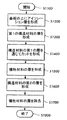
図2は、本発明による、マイクロマシン化された装置を製造するための方法の第1の模範的実施例を概説するフローチャートである。製造プロセスは、ステップS100で、例えばシリコン等の基板において、開始する。ステップS200で、基板の上にアイソレーション層が形成される。アイソレーション層は、例えばシリコン窒化物のような、いかなる適切な誘電体でも有り得る。ステップS300で、第1の構造材料の層はその後、アイソレーション層の上に形成される。第1の構造材料の層は、例えば、ポリシリコンあるいは単一結晶シリコンであり得る。ステップS100−S300は別個のステップとして示される一方、このプロセスは、事前に製造された絶縁体上のシリコンウェーハで開始し得ることが理解されるべきである。
【0036】
第1の構造材料の層は、例えば、ステップS400に進む前にエッチングプロセスによって、所望されるようにプロセスされ得る。ステップS400で、第1の犠牲材料の層が、第1の構造材料の層の上に形成される。その後、ステップS500で、第2の構造材料の層が、第1の犠牲材料の層の上に形成される。第2の犠牲材料の層は、ステップS600で第2の犠牲材料の層の上に形成され、ステップS700で第2の犠牲材料の層の上に保護層が形成される。
【0037】
第1と第2の犠牲材料の層は、ステップS800で除去される。例えば、第1と第2の犠牲材料の層は、他の層のの材料を大きく腐食するために許容されない、フッ化水素のような開放エッチングに曝され得る。第1と第2の犠牲材料の層は、側面を除いて完全に、他の層で覆われるので、エッチング液(etchant)は、第1と第2の犠牲材料の層を同様のやり方で腐食することになる。このようにして、第1と第2の犠牲材料の層の間に配置された第2の構造材料の層の表面の双方が、腐食液(etchant)に同様に暴露されることになる。
【0038】
第1と第2の犠牲材料の層が除去された後に、ステップS900で保護層が除去され得る。しかし保護層は、素子の他の構造層を形成し得る。その場合には、ステップS900は実行されないことになる。プロセスはその後、ステップS1000で終了する。しかし、最終素子を得るための、更なるプロセッシングが可能であることが理解されねばならない。
【0039】
図3と4は、本発明の第1の模範的方法による製造の段階での、図1の模範的なエゼクタを示す。ここに示されるように、アイソレーション(isolation)層220は、基板210の上に形成され、電極230は、アイソレーション層220の上に形成される。第1の犠牲材料の層260は、電極230の上に形成される。エゼクタのための膜構造(膜と膜アンカー)を形成する第1の構造材料の層240は、第1の犠牲材料の層260の上に形成される。第2の犠牲材料の層270は、第1の構造材料の層240の上に形成される。
【0040】
本発明の第1の模範的方法によって、第2の犠牲材料の層270の上に保護層250が形成される。ここに示されるように、保護層250は、例えばアイソレーション層220に接続する、一つあるいはそれ以上のサポート脚252の上に形成され得る。図4に示すように、本方法によってサポート脚252は、腐食液が第1と第2の犠牲材料の層260と270にアクセスするのを可能とするために膜アンカー内に形成された、あるいはその間に形成された側面のエッチングホール(etch holes)に対応して、スルーホール254から離れて間隔が空けられねばならないか、あるいは、スルーホール254を含まねばならない。
【0041】
図4に示されるように第1の模範的方法は、開放エッチング(そこで腐食液280が第1と第2の犠牲材料の層260と207を除去する)を採用する。第1と第2の犠牲材料の層206と207は、側面エッチングホール(lateral etch holes)と対応するスルーホール(through holes)254を除いてその全面を被覆されるので、腐食液280は、第1及び第2の犠牲材料の層206と207を同様のやり方で腐食する。
【0042】
図5は、開放エッチングステップ(第2の犠牲材料の層270の上部表面が暴露されるように、ここで保護層250が省略される(omitted))に曝されるエゼクタの断面図である。図5の矢印で図示されるように、開放エッチング中に、腐食液280は、第2の犠牲材料の層270の全体の上部表面を腐食することを許される。その結果、第2の犠牲材料の層270が、第1の犠牲材料の層260(これは、側面エッチングホールを経由して腐食液にのみ暴露される)に比べてより高い率で除去される。例えば、側面エッチングホールを用いた15分のエッチングが必要な、半径200ミクロンを持つ膜には、標準エッチングホール(犠牲材料の上の層で形成される)が用いられる時に、2.5分のエッチングのみが必要とされる。
【0043】
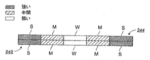
図4と5に示された模範的プロセスの双方で、第1の構造材料の層240の低部の部分は、第1の犠牲材料の層260が徐々に除去されるにつれて、徐々に腐食液280に暴露される。こうして、側面エッチングホールにより近い、第1の構造材料の層240の低部の一部分は、側面エッチングホールから、より遠い第1の構造材料の層240の低部の内部部分に比べてより長い期間、開放エッチングに曝される。これが概略的に、第1の構造材料の層240の低部242が、比較的強力な腐食S,比較的弱い腐食W,及び中間の腐食M,に曝される部分を持つ、図6と図7に示される。
【0044】
構造層がポリシリコンで作られ、犠牲材料はニ酸化ケイ素であり、開放腐食液がフッ化水素酸(HF)である場合には、腐食のメカニズムは現在以下の様に理解されている。ポリシリコンの種々の結晶定位(crystal orientation)の結晶の間の境界は、ポリシリコン層あるいはフィルム内のいかなる不純物に対しても集合点(collection point)となる傾向を持つ。いくつかのポリシリコンフィルムは、少量の酸素のような不純物を持つ。結晶境界において酸素が集塊する時に、酸素は、フッ化水素酸に対するターゲットとなる。これによって、ポリシリコンフィルムの表面が、結晶境界において弱められるか、あるいは破壊される。
【0045】
本発明の第1の模範的方法で、第1の構造材料の層240の上部部分もまた、第2の犠牲材料の層270が徐々に除去されるにつれて、腐食液280に徐々に暴露される。こうして、側面エッチングホールにより近い第1の構造材料の層240の上部部分の一部分が、側面エッチングホールから離れた第1の構造材料の層240の低部の外側部分に比べて、より長い期間開放エッチングに曝される。図6に概説されるように、第1の構造材料の層240の上部部分244は、比較的強い腐食S,比較的弱い腐食W,及び中程度の腐食Mに曝される部分を持つ。
【0046】
しかし、図5に示される模範的プロセスによると、第1の構造材料の層240の実質的に全ての上部部分244が、第2の犠牲材料の層270が除去されると直に、実質的に同じ時間において腐食液280に暴露される。腐食液280が第2の犠牲材料の層270の上部表面全体を腐食するので、第1の構造材料の層240の上部部分244の全体が、比較的強力な腐食Sに曝される。
【0047】
第1の構造材料の層240上での腐食液280の腐食は、第1の構造材料の層240を弱める。このようにして、比較的強力な腐食Sは、比較的弱い腐食Wに比べてより大きな損傷を引き起こす中程度の腐食Mに比べて、より大きな損傷を引き起こす。従って、第1の構造材料の層240は、側面エッチングホール(etch holes)を用いて、異なるレベルの腐食に曝される。そして、第1の構造材料の層240の中央に向けて第1の構造材料の層240が強度傾斜を持つことになり、比較的強力な腐食Sに曝される部分は、中程度の腐食Mに曝される部分(これは、比較的弱い腐食に曝される部分Wに比べてより強い)より強い。
【0048】
図7に示されるように図5の模範的プロセスは、上部部分244が、低部242に類似する強度傾斜を持たないようにする。上部部分244全体が、比較的強力な腐食Sに曝されるので、上部部分244の全体は、中位の腐食Mと比較的弱い腐食Wに曝される、低部242の部分に比べてより弱い。第1の構造材料の層240内の固有の応力は、第1の構造材料の層240を撓ませる。つまり、上部部分244が凸状で、低部242が凹状であるように、第1の構造材料の層240は、曲がる。上述のように、これは所望されない結果である。
【0049】
しかし図6に示されるように、本発明の第1の模範的方法は、より低い(lower)及びより高い(upper)部分242と244が、実質的に同じ強度傾斜を持つようにする。これが、いかなるエッチングによってもたらされる、第1の構造材料の層240の撓みをも削減し、あるいは除去する。
【0050】
図8は、本発明によるマイクロマシーン化された装置を製造するための方法の第2の模範的実施例を概説するフローチャートである。製造プロセスは、ステップS1100で、例えばシリコンのような基板で開始する。ステップS1200で、アイソレーション層(isolation layer)が、基板の上に形成される。アイソレーション層は、例えば窒化ケイ素のような、いかなる適切な誘電体でも有り得る。第1の構造材料の層はその後、ステップS1300で、アイソレーション層の上に形成される。第1の構造材料の層は、例えば、ポリシリコンあるいは単一結晶シリコンで有り得る。ステップS1100−S1300が別個のステップとして示される一方、プロセスは、事前に製造されたシリコン上に絶縁部を持つウェーハで開始し得ることが理解されるべきである。
【0051】
ステップS1400で、第1の構造材料の層を通じてカットが作られ、アイソレーション層の一部分を暴露させる。その後、ステップS1500で、犠牲材料の層が第1の構造材料の層の上に形成される。第2の構造材料の層が、ステップS1600で犠牲材料の層の上に形成される。
【0052】
犠牲材料の層はその後、ステップS1700で除去される。例えば、犠牲材料の層は、他の層の材料を腐食することが許されない、フッ化水素酸のような開放エッチングに暴露され得る。犠牲材料の層は完全に、側面を除いて他の層によって覆われるので、腐食液は犠牲材料の層を側面から腐食することになる。
【0053】
第1の構造材料の層におけるカットは好ましくは、外側の端部からサイドにおいて(at the side)走るチャンネルを形成する。アイソレーション層/犠牲材料層はカットで干渉するので、エッチングは、そのようなチャンネルに沿ってより迅速に進行し、増加された犠牲材料への腐食液のアクセスを提供し、必要なエッチング時間を減少させる。一旦犠牲材料の層が除去されると、プロセスはステップS1800で終了する。
【0054】
図9−11は、本発明の第2の模範的方法による製造の段階における図1の模範的エゼクタを示す。ここに示されるように、エゼクタのための電極を形成する第1の構造材料の層320が、アイソレーション層310及び/又は基板(図示せず)の上に形成される。第1の構造材料の層320は、少なくとも一つのカット322を含む。第1の犠牲材料の第1の層330は、構造材料の第1の層320の上に形成される。第1の犠牲材料の第1の層330は、アイソレーション層310とのインターフェースを、少なくとも一つのカット322において形成する。これは、図10と11に示されるような、それぞれ、カットを持つ、持たない、部分的な断面を形成する。図示のように、少なくとも一つのカット322が、チャンネルとして形成され得る。
【0055】
開放エッチング中に腐食液は、第1の犠牲材料の第1の層330を、少なくとも一つのカット322においてより迅速に除去する。これは結果として、第1の犠牲材料の第1の層330を除去するための開放エッチングに対する減少したエッチング時間をもたらす。特に少なくとも一つのカット322がチャンネルとして形成される時に、少なくとも一つのカット322が腐食液が、第1の犠牲材料の第1の層330のより広いエリアを、腐食液を側面のエッチングホールから第1の犠牲材料の第1の層330内に浸透させてチャネリングする(channeling)ことによって腐食させることを許容する。
【0056】
第1の犠牲材料とアイソレーション層の材料が適切に選択される時に、第1の犠牲材料の第1の層330を除去するための開放エッチングのためのエッチング時間は、更により削減される。例えば、アイソレーション層材料は、窒化ケイ素のような窒化物で有り得る。第1の犠牲材料は、二酸化ケイ素のような酸化物であり得る。これは、少なくとも一つのカット322において、酸化物−窒化物インターフェースを提供する。実験によって、フッ化水素酸の開放エッチングが、酸化層を、酸化物−窒化物インターフェースに沿って、酸化物−ポリシリコンインターフェースに比べてより迅速に除去することが示された。
【0057】
更に実験によって、本発明の第2の模範的方法による製造が、エッチング速度を、30−50%増加させることが示された。上述のように、開放エッチングのための削減されたエッチング時間は結果としてを、マイクロ素子の構造的及び電気的構成要素へのより少ない損傷もたらす。適切な数のカットを用いることによって、開放エッチングのためのエッチング時間が、機械的劣化及び/又は電気回路の開放を避けるために十分なだけ削減される。
【0058】
図12は、本発明によってマイクロマシン化された素子を製造するための方法の第3の模範的実施例を概説するフローチャートである。製造プロセスは、ステップS2100で、例えばシリコンのような基板で開始する。ステップS2200で、アイソレーション層が、基板の上に形成される。アイソレーション層は、例えば窒化ケイ素のような、いかなる適切な誘電体でも有り得る。構造材料の第1の層はその後、ステップS2300で、アイソレーション層の上に形成される。第1の構造材料の層は、例えばポリシリコンあるいは単一の結晶シリコンであり得る。ステップS2100−S2300は、別個のステップとして示される一方、プロセスは、事前に製造されたシリコン上に絶縁物が載ったウェーハで開始し得ることが理解されなければならない。
【0059】
ステップS2400で、アイソレーション層の一部分を暴露するために、第1の構造材料の層を通じてカットが作られる。その後ステップS2500で、第1の犠牲材料の層が、第1の構造材料の層の上に形成される。第2の構造材料の層が、ステップS2600で、第1の犠牲材料の層の上に形成される。ステップS2700で、第2の犠牲材料の層が、第2の構造材料の層の上に形成される。保護層はその後、ステップS2800で、第2の犠牲材料の層の上に形成される。保護層を通じたカットが、ステップS2900で作られ、第2の犠牲材料の層の一部分を暴露する。
【0060】
ステップS3000で、第3の犠牲材料の層と第2の犠牲材料の層との間にインターフェースが形成されるようなやり方で、第3の犠牲材料の層が保護層の上に形成される。第3の犠牲材料の層は、例えばエッチングによって、第2の犠牲材料の層に比して、より除去が許されない材料で作られる。例えば、第3の犠牲材料の層は窒化物であり得、第2の犠牲材料の層は酸化物であり得、保護層内のカットにおいて窒化物/酸化物インターフェースを形成し得る。
【0061】
第1と第2の犠牲材料の層は、ステップS3100で除去される。例えば、第1及び第2の犠牲材料の層は、他の層の材料を大きく腐食することが許されない、フッ化水素酸のような開放エッチングに曝され得る。第1と第2の犠牲材料の層は、側面を除いて完全に他の層によって覆われるので、腐食液は第1及び第2の犠牲材料の層を、類似のやり方で腐食することになる。従って、第1と第2の犠牲材料の層の間に配置された第2の構造材料の双方の層が、類似する、腐食液に対する暴露を持つことになる。更にカットにおけるインターフェースは、上述のように、必要なエッチング時間を減少させる。
【0062】
第1及び第2の犠牲材料の層が除去された後に、第3の犠牲材料の層と保護層は、ステップS3200とS3300で、それぞれ除去され得る。プロセスはその後、ステップS1000で停止する。
【0063】
図13と図14は、本発明の第3の模範的方法による製造段階での、図1の模範的エゼクタの部分断面を示す。これまでの実施例におけるように、エゼクタのための電極を形成する第1の構造材料の層420が、アイソレーション層410及び/又は基板(図示せず)の上に形成される。第1の構造材料の層420は、少なくとも一つのカット422を含む。第1の犠牲材料の第1の層430が、構造材料420の第1の層420の上に形成される。第1の犠牲材料の第1の層430は、少なくとも一つのカット422において、アイソレーション層410とのインターフェースを形成する。
【0064】
図13と図14に示されるように、のエゼクタ膜構造を形成する第2の構造材料の層440が、第1の犠牲材料の第1の層430の上に形成される。第1の犠牲材料の第2の層450が、第2の構造材料の層440の上に形成される。
【0065】
本発明の第3の模範的方法によって、保護層460が第1の犠牲材料の第2の層450の上に形成される。第1の実施例に関する上述の説明ように、保護層460は、例えばアイソレーション層410に接続する一つあるいはそれ以上のサポート脚462上に形成され得る。再び、図9に示されるように、サポート脚462は、腐食液のアクセスを許容するために、膜アンカー中に、あるいはその間に形成された側面のエッチングホールに対応して、スルーホール464から間隔が空けられるか、あるいは、それを含むべきである。
【0066】
図14に示されるように、少なくとも一つのカット466が、保護層460に形成される。図13は、カット無しの、一部分の部分断面を示す。第3の犠牲材料の層470が、保護層460の上に形成される。第3の層470は、第1の犠牲材料に比べて、腐食をより許容しない、第2の犠牲材料で作られねばならない。これは、第1の犠牲材料の第2の層450が、第1の犠牲材料の第2の層450の端部からを除いて腐食されるのを防ぐ。
【0067】
第3の犠牲材料の層470は、少なくとも一つのカット466において、第1の犠牲材料の第2の層450とのインターフェースを形成する。再度、少なくとも一つのカット466が、図示するようにチャンネルとして形成され得る。
【0068】
上述のように、開放エッチング中に腐食液は、第1の犠牲材料の第1の層430と第1の犠牲材料の第2の層450を、それぞれのカット422と466においてより迅速に除去することになる。これにより結果として、第1の犠牲材料430と450の第1と第2の層を除去するための開放エッチングのための減少されたエッチング時間がもたらされる。カット422と466は、腐食液が、腐食液を側面エッチングホールから第1の犠牲材料430と450の第1と第2の層内にチャネリングすることによって、第1の犠牲材料の、第1と第2の層430と450のより広いエリアを腐食することを可能とする。上述のように、アイソレーション層410は、窒化ケイ素のような窒化物で有り得、第1の犠牲材料は、二酸化ケイ素のような酸化物で有り得る。第2の犠牲材料は、窒化ケイ素のような窒化物で有り得る。
【0069】
本発明は、以上概説した模範的な実施例との関係で説明されてきた一方、多くの代替物,修正,及び変更が当業者にとって明白であること、は明白である。従って、上述の本発明の模範的実施例は、説明目的であることが意図される。本発明の精神と視野から離れること無しに、種々の変更が為され得る。
【図面の簡単な説明】
【図1】本発明の方法によって製造され得るマイクロマシン化された液体エゼクタ(ejector)の模範的実施例の断面図。
【図2】本発明によるマイクロマシン化された装置を製造するための方法の第1の模範的実施例を概説するフローチャート。
【図3】本発明の第1の模範的方法による製造段階での、図1の模範的エゼクタの断面図。
【図4】本発明の第1の模範的方法による開放エッチングステップに従って、側面のエッチングホールに沿ってとられた、図3の模範的エゼクタの断面図。
【図5】異なる方法による開放エッチングステップに従ったエゼクタの断面図。
【図6】図4の開放エッチングステップ中の膜構造が被った腐食(attack)の程度の概略表現。
【図7】図5の開放エッチングステップ中に膜構造が被った腐食の程度の概略表現。
【図8】本発明によるマイクロマシン化された装置を製造するための方法の第2の模範的実施例を概説するフローチャート。
【図9】本発明の第2の模範的方法による製造の段階で、縮小スケールで示される、図1の模範的エゼクタの部分上面図。
【図10】図9のカット無しのエゼクタの一部分の部分断面図。
【図11】図9のカット有りのエゼクタの一部分の部分断面図。
【図12】本発明によるマイクロマシン化された装置を製造するための方法の第3の模範的実施例を概説するフローチャート。
【図13】本発明の第3の模範的方法による製造の段階での図1の模範的エゼクタ(カット無し)の一部分の部分断面図。
【図14】本発明の第3の模範的方法による製造の段階での図1の模範的エゼクタ(カット有り)の他の部分の部分的断面図。
【符号の説明】
100 液体エゼクタ
110 基板
120 アイソレーション層
130 電極
140 膜構造
142 膜
144 膜アンカー
150 表面プレート構造
152 表面プレート
154 ノズルホール
160 膜チャンバ
210 基板
220 アイソレーション層
230 電極
240 第1の構造材料の層
250 保護層
252 サポート脚
254 スルーホール
260 第1の犠牲材料の層
270 第2の犠牲材料の層
280 腐食液[0001]
BACKGROUND OF THE INVENTION
The present invention relates to a method for forming a film structure for a micro device, the film structure itself, and a micro device comprising the film structure.
[0002]
[Prior art]
Various micro devices having a film structure are known. For example, microelements that handle liquids are known that use a membrane structure to control liquid movement. Exemplary microelements for transporting chemicals for chemical changes, for transporting drugs and biological samples, for depositing photoresists and other liquids in the semiconductor and flat panel industry, A thin, narrow plastic that can be used as a permanent and / or removable gasket for handling DNA procedures, transporting drugs and biological materials for interaction research and analysis, or in a micromachine Includes micromachined injection elements for ink jet recording or printing to deposit layers. See, for example, US Pat.
[0003]
Various manufacturing techniques are known for microelements, such as surface and / or bulk micromachining techniques. Planar manufacturing process steps common to the integrated circuit (IC) manufacturing industry can be used to manufacture microelectromechanical devices or micromechanical devices. The standard building block process consists of depositing and photolithography patterning of alternating layers on the substrate. The alternating layers consist of low stress polycrystalline silicon (also called polysilicon) and a sacrificial material such as silicon dioxide on the substrate. Vias etching through the sacrificial layer results in anchor points to the substrate and between the polysilicon layers. The polysilicon layer is patterned to form the mechanical elements of the micromachined device. The mechanical elements are thus formed layer by layer in a series of deposition and patterning process steps. The silicon dioxide layer is then removed by exposure to a selective etchant such as hydrofluoric acid (HF) (which does not etch the polysilicon layer). This frees the mechanical elements formed in the polysilicon layer for operation therefrom. Again, see for example the incorporated '198 patent.
[0004]
The resulting micromachined device is typically a first layer of polysilicon that provides an electrical interconnect and / or voltage reference plane, and a simple cantilever to complex system (s). And up to three additional layers of polysilicon, including mechanical elements with a range up to (such as an electrostatic motor connected to a gear). The layer thickness is typically about 0.5-2 microns, while typical in-plane lateral dimensions range from 1 to several hundred microns. Since the entire process is based on standard IC manufacturing techniques, hundreds to thousands of devices can be manufactured in batches and fully assembled on one silicon substrate (without any need for component assembly).
[0005]
In particular, the microelements can be manufactured using the SUMMiT process. The SUMMiT process is based on various US patents belonging to Sandia NationalLabs (5,783,340, 5,798,283, 5,804,084, 5,919,548, 5,963, 788, and 6,053,208, each of which is incorporated herein by reference in its entirety. The SUMMiT process is mainly covered by the '084 and' 208 patents. In particular, the method discussed in pending US patent application Ser. No. 09 / 723,243 (filed Nov. 28, 2000, which is hereby incorporated by reference in its entirety) may be used.
[0006]
Chemical mechanical polishing (CMP) that planarizes various levels within a multi-level micromachined device to avoid unintentional interference between structures on different layers of the micromachined device The technique is described in US Pat. No. 5,804,084 to Nasby et al. As the relatively thick (2 μm) polysilicon and oxide layers are deposited and etched in the process described above, significant surface topography (subsequent deposition, patterning, and etching impose limitations) surface topography) appears (arisees). The surface topography is created when the layer is drape into the valley created by the previous etching step. Specific layers may be planarized to remove the processing difficulties associated with photoresist step coverage, depth of focus of photolithography equipment, and the occurrence of stinger during dry etching. Often desirable. Chemical mechanical polishing of the intermediate sacrificial layer, as discussed in US Pat. No. 5,804,084, is relatively simple to improve the topographical difficulties inherent in multilevel micromachine processes. Give quick processing. This eliminates the need for further concerns in structural design, special photoresist processes, and the use of special mask levels.
[0007]
For example, an anisotropic etching process can be used to define structures such as grooves and ridges with lower than average selectivity into a silicon substrate. The individual structures to be etched are usually defined by an etching mask applied to the silicon substrate as what is commonly referred to as a masking layer (eg, a photoresist layer). In anisotropic etching techniques, it is necessary to achieve a precisely defined recess on the side in the silicon. These deeply extending recesses should have lateral ends that are as vertical as possible. The edges of the masking layer that cover those silicon substrate regions that should not be etched are under-exposed to maintain the highest possible accuracy of the structural transition side from the mask into the silicon. Not etched. As a result, it is necessary to allow the etching to proceed only on the bottom of the structure and not on the sidewalls of the already generated structure.
[0008]
For this purpose, a plasma etching method can be used to perform the etching of the profile of the silicon substrate. In such a way, chemically reactive species and electrically charged particles (ions), with the help of electrical discharge, in the reactive gas mixture in the reactor Generated. The positively charged cations generated in this way are accelerated towards the substrate using electrical prestress applied to the silicon substrate, and actually fall vertically onto the substrate surface, etching base Promotes chemical reaction of reactive plasma species with silicon on (etching base).
[0009]
A particular type of anisotropic etching process is described in US Pat. No. 5,501,893 to Laermer et al. This particular type of etching process is broadly referred to as a Bosch etch. According to Bosch etching, an anisotropic etching process is achieved by alternating sequential etching and polymerization steps. As a result, in an advantageous manner, the simultaneous presence of etching species and polymer formers in the plasma is completely avoided. Thus, a deep structure with vertical edges is realized with a very high etching rate on the silicon substrate.
[0010]
[Patent Document 1]
US Pat. No. 6,127,198
[0011]
Summary of the Invention
The system and method of the present invention provides a film structure with reduced deflection due to etching.
[0012]
The systems and methods of the present invention separately provide microelements having a film structure with reduced deflection due to etching.
[0013]
The system and method of the present invention separately provide a membrane structure in which the upper and lower intensity gradients are substantially the same.
[0014]
The system and method of the present invention separately provide a microelement having a membrane structure in which the upper and lower intensity gradients are substantially the same.
[0015]
The systems and methods of the present invention provide a reduced release etch time for the fabrication of microstructures and microdevices separately and independently.
[0016]
The system and method of the present invention separately provide a microelement microstructure that suffers less damage from open etching during manufacture.
[0017]
In various exemplary embodiments of the method of the present invention, a film of structural material for a microelement forms a first sacrificial material layer and a first structure over the first sacrificial material layer. Forming a layer of structural material, forming a layer of second sacrificial material on the first layer of structural material, and forming a protective layer on the layer of second sacrificial material And the first and second sacrificial material layers are fabricated by subjecting the first and second sacrificial material layers to an open etch to remove the first and second sacrificial material layers at substantially the same rate. In various embodiments, the protective layer is removed after the first and second layers of sacrificial material are subjected to open etching. In various embodiments, the protective layer is mechanically removed. In various other embodiments, the protective layer is chemically removed.
[0018]
According to various exemplary embodiments, the first structural material layer may be formed by a layer of polysilicon. In various embodiments, the protective layer may be formed by a polysilicon protective layer. In other embodiments, the first layer of structural material and / or the protective layer may be formed by a single layer of crystal silicon. The first and second layers of sacrificial material may be formed by first and second oxide layers. According to various exemplary embodiments, the protective layer forms a plurality of outer support legs around the first layer of structural material, forms a protective layer over the second layer of sacrificial material, and the support legs Can be formed by adhering to. In various embodiments, the plurality of support legs and the protective layer can be polysilicon. In various other embodiments, the plurality of support legs can be nitride.
[0019]
In accordance with a further exemplary embodiment of the present invention, a film produced according to any of the above embodiments further comprises a second structural material layer (on which a first sacrificial material layer is formed). Forming at least one cut in the second layer of structural material and forming at least one cut in the protective layer. In various exemplary embodiments, an interface is created between the first sacrificial material layer and the third material layer in at least one cut of the second structural material layer. A third material layer (on which a second structural material layer is formed) is formed, and in at least one cut of the protective layer, between the second sacrificial material layer and the fourth material layer. A layer of fourth material is formed over the protective layer so that an interface is formed therebetween.
[0020]
In various embodiments, the first and second sacrificial material layers are formed by a first sacrificial material layer, and the third and fourth material layers are of a different material than the first sacrificial material. Formed by layers.
[0021]
In various exemplary embodiments of the method of the present invention, a film of structural material for a microelement forms a first layer of a first material and is structured over the first layer of the first material. Forming a first layer of material, forming at least one cut in the first layer of structural material, and between the first material and the sacrificial material in at least one cut in the layer of first structural material; Forming a first layer of sacrificial material different from the first material over the layer of first structural material, and forming a first layer of second sacrificial material so that an interface is formed Manufactured by subjecting the layer of the first sacrificial material to open etching for removal.
[0022]
According to various exemplary embodiments, the first structural material layer is formed by a layer of polysilicon. In another embodiment, the first layer of structural material is formed by a single layer of crystalline silicon. In various embodiments, the at least one cut in the first layer of structural material may comprise at least one channel.
[0023]
In various embodiments, the first layer of first material may be formed by a first nitride layer and the first sacrificial material layer may be formed by a first oxide layer. In various embodiments, the second layer of structural material is formed on the first oxide layer. According to a further exemplary embodiment of the present invention, the film produced according to any of the above embodiments further forms a second oxide layer on the second structural material layer, Forming a protective layer on the oxide layer, forming at least one cut in the protective layer, and forming an oxide-nitride interface in at least one cut in the protective layer. Forming a second nitride layer thereon and subjecting the second oxide layer to an open etch to remove the second oxide layer.
[0024]
These and other features and advantages of the present invention are described in, or are apparent from, the following detailed description of various exemplary embodiments of the method and apparatus according to the present invention.
[0025]
DETAILED DESCRIPTION OF THE INVENTION
Various exemplary embodiments of the method and apparatus of the present invention are described in detail below with reference to the accompanying drawings.
[0026]
The method of the present invention can be used in the manufacture of a wide variety of microdevices. For example, surface micromachining techniques can be used to manufacture various types of ink jet ejectors. In particular, electrostatically and magnetically actuated liquid ejectors manufactured using such techniques are small, integrated, monolithic, with drop size modulation. Has the potential for manufacturing, (no assembly or little assembly is required). Thus, the present invention builds upon existing surface micromachining technology to produce micromachined devices and structures thereof, particularly micromachined film structures and microelements containing film structures. Provides unique advantages.
[0027]
While exemplary embodiments of the present invention are now described with reference to a micromachined liquid ejector, the system and method of the present invention is suitable for the manufacture of any known or later developed microdevice. I want you to understand that it is suitable. Furthermore, while the method of the present invention will now be described with reference to a membrane structure, it will be understood that the system and method of the present invention is suitable for the manufacture of any known or later developed microstructure. I want you to do it.
[0028]
Accordingly, for exemplary purposes only, a cross-sectional view of an exemplary embodiment of a micromachined
[0029]
During manufacturing, a layer of sacrificial material is formed and etched to define the structure of the
[0030]
Manufacturing the
[0031]
Instead of forming etch holes in the
[0032]
As described above, the open etch can take longer to remove the sacrificial material using the side etch holes, and as a result, the
[0033]
The present invention provides a solution to these problems. Various embodiments of the present invention can produce film structures and the like without the deflection caused by etching. In various embodiments of the present invention, the upper layer of the membrane structure may have an intensity gradient that is substantially the same as the intensity gradient of the lower layer of the membrane structure. According to various embodiments of the present invention, a protective layer is formed over a layer of sacrificial material that is formed over the membrane structure. The protective layer only allows access to the side of the sacrificial sacrificial material (formed on the membrane structure) (similar to that provided by the side access holes). Thus, the etchant erodes the sacrificial material layer on each side of the membrane at substantially the same rate.
[0034]
Various embodiments of the present invention can produce film structures and the like with less damage from the open etch used to remove the sacrificial material layer. In various embodiments of the present invention, the time required to remove the layer of sacrificial material using an open etch is reduced. In accordance with various embodiments of the present invention, at least one cut is formed in a layer of structural material formed over or on a layer of structural material over which a layer of sacrificial material is formed. At least one cut provides an etchant with additional access to the layer of sacrificial material. Further, in various embodiments, a layer of other sacrificial material, different from the sacrificial material of the layer to be removed, is formed on the side of the layer of structural material opposite the layer of sacrificial material to be removed. Is done. In at least one cut, an interface is formed between the two sacrificial materials. Open etching proceeds faster at the interface.
[0035]
FIG. 2 is a flowchart outlining a first exemplary embodiment of a method for manufacturing a micromachined device according to the present invention. The manufacturing process starts at step S100 on a substrate such as silicon. In step S200, an isolation layer is formed on the substrate. The isolation layer can be any suitable dielectric, such as silicon nitride. In step S300, a first layer of structural material is then formed over the isolation layer. The first layer of structural material can be, for example, polysilicon or single crystal silicon. While steps S100-S300 are shown as separate steps, it should be understood that the process can begin with a silicon wafer on a pre-fabricated insulator.
[0036]
The first layer of structural material may be processed as desired, for example, by an etching process before proceeding to step S400. In step S400, a first sacrificial material layer is formed over the first structural material layer. Thereafter, in step S500, a second layer of structural material is formed over the first layer of sacrificial material. A second sacrificial material layer is formed on the second sacrificial material layer in step S600, and a protective layer is formed on the second sacrificial material layer in step S700.
[0037]
The first and second layers of sacrificial material are removed in step S800. For example, the first and second sacrificial material layers may be exposed to an open etch such as hydrogen fluoride, which is not allowed to greatly corrode the material of the other layers. Since the first and second layers of sacrificial material are completely covered with the other layers except the sides, the etchant corrodes the first and second layers of sacrificial material in a similar manner. Will do. In this way, both the surfaces of the second structural material layer disposed between the first and second sacrificial material layers will be similarly exposed to the etchant.
[0038]
After the first and second layers of sacrificial material are removed, the protective layer may be removed in step S900. However, the protective layer can form another structural layer of the device. In that case, step S900 is not executed. The process then ends at step S1000. However, it must be understood that further processing is possible to obtain the final device.
[0039]
3 and 4 show the exemplary ejector of FIG. 1 at the stage of manufacture according to the first exemplary method of the present invention. As shown here, an
[0040]
In accordance with the first exemplary method of the present invention, a
[0041]
As shown in FIG. 4, the first exemplary method employs an open etch where the
[0042]
FIG. 5 is a cross-sectional view of an ejector that is exposed to an open etch step (where the
[0043]
In both of the exemplary processes shown in FIGS. 4 and 5, the lower portion of the first
[0044]
When the structural layer is made of polysilicon, the sacrificial material is silicon dioxide, and the open etchant is hydrofluoric acid (HF), the mechanism of corrosion is now understood as follows. The boundary between the various crystal orientation crystals of polysilicon tends to be a collection point for any impurity in the polysilicon layer or film. Some polysilicon films have small amounts of oxygen-like impurities. As oxygen agglomerates at the crystal boundaries, it becomes a target for hydrofluoric acid. This weakens or breaks the surface of the polysilicon film at the crystal boundaries.
[0045]
In the first exemplary method of the present invention, the upper portion of the first
[0046]
However, according to the exemplary process shown in FIG. 5, substantially all of the
[0047]
Corrosion of the
[0048]
As shown in FIG. 7, the exemplary process of FIG. 5 prevents the
[0049]
However, as shown in FIG. 6, the first exemplary method of the present invention causes the lower and
[0050]
FIG. 8 is a flowchart outlining a second exemplary embodiment of a method for manufacturing a micromachined device according to the present invention. The manufacturing process begins at step S1100 with a substrate such as silicon. In step S1200, an isolation layer is formed on the substrate. The isolation layer can be any suitable dielectric, such as silicon nitride. A first layer of structural material is then formed over the isolation layer in step S1300. The first layer of structural material can be, for example, polysilicon or single crystal silicon. It should be understood that while steps S1100-S1300 are shown as separate steps, the process can begin with a wafer having an insulator on pre-fabricated silicon.
[0051]
In step S1400, a cut is made through the first layer of structural material to expose a portion of the isolation layer. Thereafter, in step S1500, a layer of sacrificial material is formed over the first layer of structural material. A second structural material layer is formed on the sacrificial material layer in step S1600.
[0052]
The layer of sacrificial material is then removed in step S1700. For example, a layer of sacrificial material can be exposed to an open etch, such as hydrofluoric acid, that is not allowed to corrode other layers of material. Since the layer of sacrificial material is completely covered by the other layers except the sides, the etchant will corrode the layer of sacrificial material from the sides.
[0053]
The cut in the first layer of structural material preferably forms a channel that runs from the outer end to the side. Since the isolation layer / sacrificial material layer interferes with the cut, etching proceeds more rapidly along such channels, providing increased etchant access to the sacrificial material and reducing the required etch time. Decrease. Once the sacrificial material layer is removed, the process ends at step S1800.
[0054]
FIGS. 9-11 show the exemplary ejector of FIG. 1 at a stage of manufacture according to the second exemplary method of the present invention. As shown herein, a first layer of
[0055]
During the open etch, the etchant removes the
[0056]
When the materials of the first sacrificial material and the isolation layer are properly selected, the etching time for the open etch to remove the
[0057]
Further experiments have shown that manufacturing according to the second exemplary method of the present invention increases the etch rate by 30-50%. As mentioned above, the reduced etch time for open etching results in less damage to the structural and electrical components of the microelement. By using an appropriate number of cuts, the etching time for open etching is reduced enough to avoid mechanical degradation and / or opening of the electrical circuit.
[0058]
FIG. 12 is a flowchart outlining a third exemplary embodiment of a method for fabricating a micromachined device according to the present invention. The manufacturing process starts at step S2100 with a substrate such as silicon. In step S2200, an isolation layer is formed on the substrate. The isolation layer can be any suitable dielectric, such as silicon nitride. A first layer of structural material is then formed over the isolation layer in step S2300. The first layer of structural material can be, for example, polysilicon or single crystalline silicon. While steps S2100-S2300 are shown as separate steps, it should be understood that the process may begin with a wafer with an insulator on pre-fabricated silicon.
[0059]
In step S2400, a cut is made through the first layer of structural material to expose a portion of the isolation layer. Thereafter, in step S2500, a first sacrificial material layer is formed over the first structural material layer. A second layer of structural material is formed on the first layer of sacrificial material in step S2600. In step S2700, a second layer of sacrificial material is formed over the second layer of structural material. A protective layer is then formed over the second layer of sacrificial material in step S2800. A cut through the protective layer is made in step S2900, exposing a portion of the second layer of sacrificial material.
[0060]
In step S3000, a third sacrificial material layer is formed on the protective layer in such a manner that an interface is formed between the third sacrificial material layer and the second sacrificial material layer. The layer of the third sacrificial material is made of a material that is less tolerated than the second layer of sacrificial material, for example by etching. For example, the third sacrificial material layer can be a nitride, the second sacrificial material layer can be an oxide, and can form a nitride / oxide interface at a cut in the protective layer.
[0061]
The first and second layers of sacrificial material are removed in step S3100. For example, the layers of the first and second sacrificial materials can be exposed to an open etch such as hydrofluoric acid that is not allowed to greatly corrode the materials of the other layers. Since the first and second layers of sacrificial material are completely covered by other layers except for the sides, the etchant will corrode the first and second layers of sacrificial material in a similar manner. . Thus, both layers of the second structural material disposed between the first and second layers of sacrificial material will have similar exposure to the etchant. Furthermore, the interface at the cut reduces the required etch time, as described above.
[0062]
After the first and second sacrificial material layers are removed, the third sacrificial material layer and the protective layer may be removed in steps S3200 and S3300, respectively. The process then stops at step S1000.
[0063]
13 and 14 show a partial cross-section of the exemplary ejector of FIG. 1 during the manufacturing stage according to the third exemplary method of the present invention. As in previous embodiments, a first layer of
[0064]
As shown in FIGS. 13 and 14, a second
[0065]
In accordance with the third exemplary method of the present invention, a
[0066]
As shown in FIG. 14, at least one
[0067]
The third
[0068]
As described above, during the open etch, the etchant removes the
[0069]
While the invention has been described in connection with the exemplary embodiments outlined above, it will be apparent that many alternatives, modifications and variations will be apparent to those skilled in the art. Accordingly, the exemplary embodiments of the invention described above are intended to be illustrative. Various changes may be made without departing from the spirit and scope of the invention.
[Brief description of the drawings]
FIG. 1 is a cross-sectional view of an exemplary embodiment of a micromachined liquid ejector that can be manufactured by the method of the present invention.
FIG. 2 is a flowchart outlining a first exemplary embodiment of a method for manufacturing a micromachined device according to the present invention.
FIG. 3 is a cross-sectional view of the exemplary ejector of FIG. 1 at a manufacturing stage according to the first exemplary method of the present invention.
4 is a cross-sectional view of the exemplary ejector of FIG. 3 taken along a side etch hole according to an open etch step according to the first exemplary method of the present invention.
FIG. 5 is a cross-sectional view of an ejector following an open etch step according to a different method.
6 is a schematic representation of the degree of attack experienced by the film structure during the open etching step of FIG.
7 is a schematic representation of the degree of corrosion experienced by the film structure during the open etching step of FIG.
FIG. 8 is a flowchart outlining a second exemplary embodiment of a method for manufacturing a micromachined device according to the present invention.
9 is a partial top view of the exemplary ejector of FIG. 1, shown on a reduced scale, during manufacturing according to the second exemplary method of the present invention.
10 is a partial cross-sectional view of a portion of the ejector without cut of FIG. 9;
11 is a partial cross-sectional view of a part of the ejector with a cut in FIG. 9;
FIG. 12 is a flowchart outlining a third exemplary embodiment of a method for manufacturing a micromachined device according to the present invention.
13 is a partial cross-sectional view of a portion of the exemplary ejector (no cut) of FIG. 1 at a stage of manufacture in accordance with the third exemplary method of the present invention.
14 is a partial cross-sectional view of another portion of the exemplary ejector (with cut) of FIG. 1 at a stage of manufacture in accordance with the third exemplary method of the present invention.
[Explanation of symbols]
100 liquid ejector
110 substrates
120 Isolation layer
130 electrodes
140 Membrane structure
142 Membrane
144 Membrane anchor
150 Surface plate structure
152 Surface plate
154 Nozzle hole
160 membrane chamber
210 Board
220 Isolation layer
230 electrodes
240 First layer of structural material
250 protective layer
252 Support leg
254 through hole
260 First sacrificial material layer
270 Second sacrificial material layer
280 Corrosive liquid
Claims (2)
前記アイソレーション層に接続され前記第1の犠牲材料の層の側面を覆うアンカーにより支持される第1の構造材料の層であって、前記アンカーには腐食液が前記第1の犠牲材料にアクセスするためのエッチングホールが形成された第1の構造材料の層を、前記第1の犠牲材料の層の上に形成するステップと、
第2の犠牲材料の層を前記第1の構造材料の層の上に形成するステップと、
前記アイソレーション層に接続され前記第2の犠牲材料の層の側面を覆う脚により支持される保護層であって、前記脚には腐食液が前記第2の犠牲材料にアクセスするためのスルーホールが含まれている保護層を、前記第2の犠牲材料の層の上に形成するステップと、
前記第1の犠牲材料の層及び前記第2の犠牲材料の層を開放エッチングに曝して除去するステップであって、腐食液が前記第1の犠牲材料の側面を覆う前記アンカーに形成されたエッチングホールを通って該第1の犠牲材料の側面から腐食させ、腐食液が前記第2の犠牲材料の側面を覆う前記脚に形成されたスルーホールを通って該第2の犠牲材料の側面から腐食させることにより、前記第1の構造材料が腐食液により受ける損傷の大きさが、水平方向に沿って該第1の構造材料の上部及び下部において同一とされるようになっているステップと、
を含むことを特徴とする、マイクロ素子のための構造材料の膜を製造するための方法。 Forming a layer of first sacrificial material over the isolation layer formed on the substrate,
A layer of a first structural material supported by an anchor connected to the isolation layer and covering a side of the layer of the first sacrificial material, wherein the anchor has an etchant accessing the first sacrificial material comprising the steps of a first layer of structural material etching hole is formed in order to form on the layer of the first sacrificial material,
Forming a layer of second sacrificial material over the layer of the first structural material,
A protective layer supported by a leg connected to the isolation layer and covering a side surface of the layer of the second sacrificial material, wherein the leg has a through-hole for allowing an etchant to access the second sacrificial material Forming a protective layer comprising: over the second layer of sacrificial material ;
Removing the first sacrificial material layer and the second sacrificial material layer by exposing to an open etch, wherein an etchant is formed on the anchor covering a side of the first sacrificial material; Corrosion is caused from the side of the first sacrificial material through a hole, and corrosive liquid is corroded from the side of the second sacrificial material through a through hole formed in the leg covering the side of the second sacrificial material. A step in which the magnitude of damage to the first structural material due to the corrosive liquid is made equal in the upper and lower portions of the first structural material along the horizontal direction;
Characterized in that it comprises a method for producing the film of the structural material for the micro devices.
前記アイソレーション層に接続され前記第1の犠牲材料の層の側面を覆うアンカーにより支持される構造材料の層であって、前記アンカーには腐食液が前記第1の犠牲材料にアクセスするためのエッチングホールが形成された構造材料の層を、前記第1の犠牲材料の層の上に形成するステップと、
第2の犠牲材料の層を前記構造材料の層の上に形成するステップと、
前記アイソレーション層に接続され前記第2の犠牲材料の層の側面を覆う脚により支持される保護層であって、前記脚には腐食液が前記第2の犠牲材料にアクセスするためのスルーホールが含まれている保護層を、前記第2の犠牲材料の層の上に形成するステップと、
前記第1の犠牲材料の層及び前記第2の犠牲材料の層を開放エッチングに曝して除去するステップであって、腐食液が前記第1の犠牲材料の側面を覆う前記アンカーに形成されたエッチングホールを通って該第1の犠牲材料の側面から腐食させ、腐食液が前記第2の犠牲材料の側面を覆う前記脚に形成されたスルーホールを通って該第2の犠牲材料の側面から腐食させるステップと、
により製造された前記構造材料の層であって、腐食液により受けた損傷の大きさが、水平方向に沿って該構造材料の上部及び下部において同一とされている前記構造材料の層、
を備えたことを特徴とするマイクロ素子のための膜。 Forming a layer of a first sacrificial material on an isolation layer formed on a substrate;
A layer of structural material connected to the isolation layer and supported by an anchor covering a side surface of the layer of the first sacrificial material, wherein the anchor has an etchant for accessing the first sacrificial material Forming a layer of structural material in which etching holes are formed on the layer of first sacrificial material;
Forming a second layer of sacrificial material over the layer of structural material;
A protective layer supported by a leg connected to the isolation layer and covering a side surface of the layer of the second sacrificial material, wherein the leg has a through-hole for allowing an etchant to access the second sacrificial material Forming a protective layer comprising: over the second layer of sacrificial material;
Removing the first sacrificial material layer and the second sacrificial material layer by exposing to an open etch, wherein an etchant is formed on the anchor covering a side of the first sacrificial material; Corrosion is caused from the side of the first sacrificial material through a hole, and corrosive liquid is corroded from the side of the second sacrificial material through a through hole formed in the leg covering the side of the second sacrificial material. Step to
A layer of the structural material manufactured by the method, wherein the magnitude of damage caused by the corrosive liquid is the same in the upper and lower portions of the structural material along the horizontal direction,
A film for a microelement, comprising:
Applications Claiming Priority (2)
| Application Number | Priority Date | Filing Date | Title |
|---|---|---|---|
| US09/986,107 US7060522B2 (en) | 2001-11-07 | 2001-11-07 | Membrane structures for micro-devices, micro-devices including same and methods for making same |
| US09/986107 | 2001-11-07 |
Publications (3)
| Publication Number | Publication Date |
|---|---|
| JP2003175498A JP2003175498A (en) | 2003-06-24 |
| JP2003175498A5 JP2003175498A5 (en) | 2005-12-22 |
| JP4384844B2 true JP4384844B2 (en) | 2009-12-16 |
Family
ID=25532090
Family Applications (1)
| Application Number | Title | Priority Date | Filing Date |
|---|---|---|---|
| JP2002317115A Expired - Fee Related JP4384844B2 (en) | 2001-11-07 | 2002-10-31 | Membrane structure for microelements, microelements including film structures, and methods for making film structures |
Country Status (2)
| Country | Link |
|---|---|
| US (1) | US7060522B2 (en) |
| JP (1) | JP4384844B2 (en) |
Families Citing this family (6)
| Publication number | Priority date | Publication date | Assignee | Title |
|---|---|---|---|---|
| US7108354B2 (en) * | 2004-06-23 | 2006-09-19 | Xerox Corporation | Electrostatic actuator with segmented electrode |
| US7226146B2 (en) * | 2004-11-30 | 2007-06-05 | Xerox Corporation | Fluid ejection devices and methods for forming such devices |
| JP4907297B2 (en) * | 2005-11-11 | 2012-03-28 | 株式会社半導体エネルギー研究所 | Method for manufacturing microstructure and microelectromechanical device |
| GB0605576D0 (en) * | 2006-03-20 | 2006-04-26 | Oligon Ltd | MEMS device |
| US7998775B2 (en) * | 2009-02-09 | 2011-08-16 | Taiwan Semiconductor Manufacturing Company, Ltd. | Silicon undercut prevention in sacrificial oxide release process and resulting MEMS structures |
| DE102017102545B4 (en) | 2017-02-09 | 2018-12-20 | Infineon Technologies Ag | Semiconductor device, pressure sensor, microphone, acceleration sensor, and method of forming a semiconductor device |
Family Cites Families (13)
| Publication number | Priority date | Publication date | Assignee | Title |
|---|---|---|---|---|
| US4740410A (en) * | 1987-05-28 | 1988-04-26 | The Regents Of The University Of California | Micromechanical elements and methods for their fabrication |
| DE4241045C1 (en) * | 1992-12-05 | 1994-05-26 | Bosch Gmbh Robert | Process for anisotropic etching of silicon |
| US5963788A (en) * | 1995-09-06 | 1999-10-05 | Sandia Corporation | Method for integrating microelectromechanical devices with electronic circuitry |
| US5783340A (en) * | 1995-09-06 | 1998-07-21 | Sandia Corporation | Method for photolithographic definition of recessed features on a semiconductor wafer utilizing auto-focusing alignment |
| US5798283A (en) * | 1995-09-06 | 1998-08-25 | Sandia Corporation | Method for integrating microelectromechanical devices with electronic circuitry |
| US5804084A (en) * | 1996-10-11 | 1998-09-08 | Sandia Corporation | Use of chemical mechanical polishing in micromachining |
| US5919548A (en) * | 1996-10-11 | 1999-07-06 | Sandia Corporation | Chemical-mechanical polishing of recessed microelectromechanical devices |
| US6610440B1 (en) * | 1998-03-10 | 2003-08-26 | Bipolar Technologies, Inc | Microscopic batteries for MEMS systems |
| US6127198A (en) * | 1998-10-15 | 2000-10-03 | Xerox Corporation | Method of fabricating a fluid drop ejector |
| JP3486124B2 (en) * | 1998-12-28 | 2004-01-13 | 三菱電機株式会社 | High pressure fuel pump device |
| US6472332B1 (en) * | 2000-11-28 | 2002-10-29 | Xerox Corporation | Surface micromachined structure fabrication methods for a fluid ejection device |
| US6587613B2 (en) * | 2001-07-24 | 2003-07-01 | Innovative Technology Licensing, Llc | Hybrid MEMS fabrication method and new optical MEMS device |
| US6936183B2 (en) * | 2001-10-17 | 2005-08-30 | Applied Materials, Inc. | Etch process for etching microstructures |
-
2001
- 2001-11-07 US US09/986,107 patent/US7060522B2/en not_active Expired - Fee Related
-
2002
- 2002-10-31 JP JP2002317115A patent/JP4384844B2/en not_active Expired - Fee Related
Also Published As
| Publication number | Publication date |
|---|---|
| JP2003175498A (en) | 2003-06-24 |
| US7060522B2 (en) | 2006-06-13 |
| US20030087468A1 (en) | 2003-05-08 |
Similar Documents
| Publication | Publication Date | Title |
|---|---|---|
| de Boer et al. | Micromachining of buried micro channels in silicon | |
| US6599436B1 (en) | Formation of interconnections to microfluidic devices | |
| US7439093B2 (en) | Method of making a MEMS device containing a cavity with isotropic etch followed by anisotropic etch | |
| US7504757B2 (en) | Multi-finger z-actuator | |
| US7361524B2 (en) | Method of manufacturing floating structure | |
| US7476951B2 (en) | Selective isotropic etch for titanium-based materials | |
| US8628677B2 (en) | Forming curved features using a shadow mask | |
| EP1279639A2 (en) | Micro-fluidic devices | |
| WO2007043963A1 (en) | Fabrication of inlet and outlet connections for microfluidic chips | |
| JP2012106340A (en) | Gap tuning for surface micromachined structure in epitaxial reactor | |
| US6884732B2 (en) | Method of fabricating a device having a desired non-planar surface or profile and device produced thereby | |
| US20060278942A1 (en) | Antistiction MEMS substrate and method of manufacture | |
| JP2009537340A (en) | Multiple post structure | |
| TW200806567A (en) | Method of deep etching | |
| JP4384844B2 (en) | Membrane structure for microelements, microelements including film structures, and methods for making film structures | |
| US6544863B1 (en) | Method of fabricating semiconductor wafers having multiple height subsurface layers | |
| WO2001011672A1 (en) | Method of etching a layer using sacrificial elements | |
| US6472332B1 (en) | Surface micromachined structure fabrication methods for a fluid ejection device | |
| Chen et al. | An investigation into the characteristics of deep reactive ion etching of quartz using SU-8 as a mask | |
| Denoual et al. | Accurate double-height micromolding method for three-dimensional polydimethylsiloxane structures | |
| EP2199252A1 (en) | Method of making a micro electro mechanical system (MEMS) device | |
| JP2011091127A (en) | Si SUBSTRATE WORKING METHOD | |
| EP1241703B1 (en) | Method for masking silicon during anisotropic wet etching | |
| JP2008264951A (en) | Machining method of inclined shape | |
| Prather et al. | Novel fabrication methods for 2D photonic crystals in silicon slab waveguides |
Legal Events
| Date | Code | Title | Description |
|---|---|---|---|
| A521 | Written amendment |
Free format text: JAPANESE INTERMEDIATE CODE: A523 Effective date: 20051028 |
|
| A621 | Written request for application examination |
Free format text: JAPANESE INTERMEDIATE CODE: A621 Effective date: 20051028 |
|
| A131 | Notification of reasons for refusal |
Free format text: JAPANESE INTERMEDIATE CODE: A131 Effective date: 20080901 |
|
| A521 | Written amendment |
Free format text: JAPANESE INTERMEDIATE CODE: A523 Effective date: 20081201 |
|
| TRDD | Decision of grant or rejection written | ||
| A01 | Written decision to grant a patent or to grant a registration (utility model) |
Free format text: JAPANESE INTERMEDIATE CODE: A01 Effective date: 20090827 |
|
| A01 | Written decision to grant a patent or to grant a registration (utility model) |
Free format text: JAPANESE INTERMEDIATE CODE: A01 |
|
| A61 | First payment of annual fees (during grant procedure) |
Free format text: JAPANESE INTERMEDIATE CODE: A61 Effective date: 20090928 |
|
| FPAY | Renewal fee payment (event date is renewal date of database) |
Free format text: PAYMENT UNTIL: 20121002 Year of fee payment: 3 |
|
| R150 | Certificate of patent or registration of utility model |
Free format text: JAPANESE INTERMEDIATE CODE: R150 |
|
| FPAY | Renewal fee payment (event date is renewal date of database) |
Free format text: PAYMENT UNTIL: 20131002 Year of fee payment: 4 |
|
| R250 | Receipt of annual fees |
Free format text: JAPANESE INTERMEDIATE CODE: R250 |
|
| R250 | Receipt of annual fees |
Free format text: JAPANESE INTERMEDIATE CODE: R250 |
|
| R250 | Receipt of annual fees |
Free format text: JAPANESE INTERMEDIATE CODE: R250 |
|
| R250 | Receipt of annual fees |
Free format text: JAPANESE INTERMEDIATE CODE: R250 |
|
| LAPS | Cancellation because of no payment of annual fees |