JP4384652B2 - Fuel tank - Google Patents
Fuel tank Download PDFInfo
- Publication number
- JP4384652B2 JP4384652B2 JP2006287354A JP2006287354A JP4384652B2 JP 4384652 B2 JP4384652 B2 JP 4384652B2 JP 2006287354 A JP2006287354 A JP 2006287354A JP 2006287354 A JP2006287354 A JP 2006287354A JP 4384652 B2 JP4384652 B2 JP 4384652B2
- Authority
- JP
- Japan
- Prior art keywords
- core member
- exhaust pipe
- fuel
- fuel tank
- refueling
- Prior art date
- Legal status (The legal status is an assumption and is not a legal conclusion. Google has not performed a legal analysis and makes no representation as to the accuracy of the status listed.)
- Expired - Fee Related
Links
Images


Classifications
-
- B—PERFORMING OPERATIONS; TRANSPORTING
- B60—VEHICLES IN GENERAL
- B60K—ARRANGEMENT OR MOUNTING OF PROPULSION UNITS OR OF TRANSMISSIONS IN VEHICLES; ARRANGEMENT OR MOUNTING OF PLURAL DIVERSE PRIME-MOVERS IN VEHICLES; AUXILIARY DRIVES FOR VEHICLES; INSTRUMENTATION OR DASHBOARDS FOR VEHICLES; ARRANGEMENTS IN CONNECTION WITH COOLING, AIR INTAKE, GAS EXHAUST OR FUEL SUPPLY OF PROPULSION UNITS IN VEHICLES
- B60K15/00—Arrangement in connection with fuel supply of combustion engines or other fuel consuming energy converters, e.g. fuel cells; Mounting or construction of fuel tanks
- B60K15/03—Fuel tanks
- B60K15/035—Fuel tanks characterised by venting means
-
- B—PERFORMING OPERATIONS; TRANSPORTING
- B60—VEHICLES IN GENERAL
- B60K—ARRANGEMENT OR MOUNTING OF PROPULSION UNITS OR OF TRANSMISSIONS IN VEHICLES; ARRANGEMENT OR MOUNTING OF PLURAL DIVERSE PRIME-MOVERS IN VEHICLES; AUXILIARY DRIVES FOR VEHICLES; INSTRUMENTATION OR DASHBOARDS FOR VEHICLES; ARRANGEMENTS IN CONNECTION WITH COOLING, AIR INTAKE, GAS EXHAUST OR FUEL SUPPLY OF PROPULSION UNITS IN VEHICLES
- B60K15/00—Arrangement in connection with fuel supply of combustion engines or other fuel consuming energy converters, e.g. fuel cells; Mounting or construction of fuel tanks
- B60K15/01—Arrangement of fuel conduits
-
- B—PERFORMING OPERATIONS; TRANSPORTING
- B60—VEHICLES IN GENERAL
- B60K—ARRANGEMENT OR MOUNTING OF PROPULSION UNITS OR OF TRANSMISSIONS IN VEHICLES; ARRANGEMENT OR MOUNTING OF PLURAL DIVERSE PRIME-MOVERS IN VEHICLES; AUXILIARY DRIVES FOR VEHICLES; INSTRUMENTATION OR DASHBOARDS FOR VEHICLES; ARRANGEMENTS IN CONNECTION WITH COOLING, AIR INTAKE, GAS EXHAUST OR FUEL SUPPLY OF PROPULSION UNITS IN VEHICLES
- B60K15/00—Arrangement in connection with fuel supply of combustion engines or other fuel consuming energy converters, e.g. fuel cells; Mounting or construction of fuel tanks
- B60K15/03—Fuel tanks
- B60K15/035—Fuel tanks characterised by venting means
- B60K15/03504—Fuel tanks characterised by venting means adapted to avoid loss of fuel or fuel vapour, e.g. with vapour recovery systems
- B60K2015/03509—Fuel tanks characterised by venting means adapted to avoid loss of fuel or fuel vapour, e.g. with vapour recovery systems with a droplet separator in the vent line
-
- B—PERFORMING OPERATIONS; TRANSPORTING
- B60—VEHICLES IN GENERAL
- B60K—ARRANGEMENT OR MOUNTING OF PROPULSION UNITS OR OF TRANSMISSIONS IN VEHICLES; ARRANGEMENT OR MOUNTING OF PLURAL DIVERSE PRIME-MOVERS IN VEHICLES; AUXILIARY DRIVES FOR VEHICLES; INSTRUMENTATION OR DASHBOARDS FOR VEHICLES; ARRANGEMENTS IN CONNECTION WITH COOLING, AIR INTAKE, GAS EXHAUST OR FUEL SUPPLY OF PROPULSION UNITS IN VEHICLES
- B60K15/00—Arrangement in connection with fuel supply of combustion engines or other fuel consuming energy converters, e.g. fuel cells; Mounting or construction of fuel tanks
- B60K15/03—Fuel tanks
- B60K15/035—Fuel tanks characterised by venting means
- B60K15/03504—Fuel tanks characterised by venting means adapted to avoid loss of fuel or fuel vapour, e.g. with vapour recovery systems
- B60K2015/03514—Fuel tanks characterised by venting means adapted to avoid loss of fuel or fuel vapour, e.g. with vapour recovery systems with vapor recovery means
-
- B—PERFORMING OPERATIONS; TRANSPORTING
- B60—VEHICLES IN GENERAL
- B60K—ARRANGEMENT OR MOUNTING OF PROPULSION UNITS OR OF TRANSMISSIONS IN VEHICLES; ARRANGEMENT OR MOUNTING OF PLURAL DIVERSE PRIME-MOVERS IN VEHICLES; AUXILIARY DRIVES FOR VEHICLES; INSTRUMENTATION OR DASHBOARDS FOR VEHICLES; ARRANGEMENTS IN CONNECTION WITH COOLING, AIR INTAKE, GAS EXHAUST OR FUEL SUPPLY OF PROPULSION UNITS IN VEHICLES
- B60K15/00—Arrangement in connection with fuel supply of combustion engines or other fuel consuming energy converters, e.g. fuel cells; Mounting or construction of fuel tanks
- B60K15/03—Fuel tanks
- B60K15/035—Fuel tanks characterised by venting means
- B60K2015/03523—Arrangements of the venting tube
-
- B—PERFORMING OPERATIONS; TRANSPORTING
- B60—VEHICLES IN GENERAL
- B60K—ARRANGEMENT OR MOUNTING OF PROPULSION UNITS OR OF TRANSMISSIONS IN VEHICLES; ARRANGEMENT OR MOUNTING OF PLURAL DIVERSE PRIME-MOVERS IN VEHICLES; AUXILIARY DRIVES FOR VEHICLES; INSTRUMENTATION OR DASHBOARDS FOR VEHICLES; ARRANGEMENTS IN CONNECTION WITH COOLING, AIR INTAKE, GAS EXHAUST OR FUEL SUPPLY OF PROPULSION UNITS IN VEHICLES
- B60K15/00—Arrangement in connection with fuel supply of combustion engines or other fuel consuming energy converters, e.g. fuel cells; Mounting or construction of fuel tanks
- B60K15/03—Fuel tanks
- B60K15/035—Fuel tanks characterised by venting means
- B60K2015/03561—Venting means working at specific times
- B60K2015/03576—Venting during filling the reservoir
Abstract
Description
本発明は、給油口と給油時排気管路とを有する自動車用燃料タンクに関する。 The present invention relates to an automobile fuel tank having a fuel filler opening and a fuel exhaust pipe.
自動車用燃料タンクの給油時排気管路は圧力制御パイプ若しくはブリーザーパイプとも呼ばれ、通常は燃料タンクの給油管とほぼ平行に延設されている。この給油時排気管路は、燃料タンクから外方へ突き出されている給油管先端の給油口マウスピース内に通じており、給油時にタンク内から押しのけられるガスは該排気管路を介してマウスピース内に達し、マウスピースに装着された給油装置の給油ガンによって給油中に吸引される(欧州方式)。 An exhaust pipe for fueling an automobile fuel tank is also called a pressure control pipe or a breather pipe, and usually extends almost in parallel with a fuel tank oiling pipe. This refueling exhaust line communicates with the mouthpiece mouthpiece at the tip of the refueling pipe protruding outward from the fuel tank, and the gas that is pushed away from the tank during refueling passes through the exhaust line to the mouthpiece. It reaches the inside and is sucked during refueling by a refueling gun of a refueling device attached to the mouthpiece (European system).
燃料タンクに対する給油時排気管路の接続個所は、タンク内に上限充填レベルまで燃料が満たされたときにタンク内に残される上部空間、即ち上部補償容積空間に通じるように一般には燃料タンクの上部位置であり、この接続箇所から給油管上端部の給油口マウスピースに亘って給油時排気管路が延在配置される。これらの給油時排気管路両端部の接続箇所の選定とは別に、給油時排気管路の配管経路については、燃料タンクを据付た状態における自動車の設計上の諸条件によって給油時排気管路の配管経路を自由に選定できない場合が多く、むしろ側部縦通材などの車体構造要素の存在により、給油時排気管路を燃料タンク側から絶えず上向き傾斜で延在するように配管することができないことが多い。その場合、給油時排気管路は途中で下向き湾曲部を含む配管経路を形成し、この下向き湾曲部によって管路中にサイホン部、すなわち給油時排気管路中の一部の区間が下方へ方向転換してから再び上方へ向きを変えて方向転換の最下部に液体炭化水素が滞留する部分を形成することがあり、これが給油時排気管路の一時的な閉塞を生じる原因となっている。このような閉塞が生じると、給油中に給油ガンの自動ノズル遮断動作が不本意にも早期に行われてしまい、給油が中断されることになる。 The connection point of the exhaust line for refueling to the fuel tank is generally the upper part of the fuel tank so that it leads to the upper space left in the tank when the fuel is filled to the upper limit filling level, that is, the upper compensation volume space. It is a position, and the exhaust pipe at the time of refueling extends from the connection location to the refueling mouth mouthpiece at the upper end of the refueling pipe. Apart from the selection of the connection points at both ends of the exhaust pipe for refueling, the piping path of the exhaust pipe for refueling depends on the design conditions of the vehicle when the fuel tank is installed. In many cases, the piping route cannot be freely selected. Rather, due to the presence of vehicle body structural elements such as side stringers, it is not possible to pipe the exhaust pipeline so that it always extends upwardly from the fuel tank. There are many cases. In that case, the exhaust pipe at the time of refueling forms a piping path including a downwardly curved part in the middle, and the siphon part, that is, a part of the section in the exhaust pipe at the time of refueling is directed downward by this downward curved part. After the conversion, the direction is changed again upward to form a portion where the liquid hydrocarbon stays in the lowermost part of the direction change, which causes a temporary blockage of the exhaust pipe during refueling. When such a blockage occurs, the automatic nozzle shut-off operation of the fuel gun is unintentionally performed at an early stage during fueling, and the fueling is interrupted.
給油時のこのような障害を防止するため、給油時に排気管路中のサイホン部に滞留した液体燃料による閉塞を破ってタンク側からの気体炭化水素が給油口マウスピース側へ通過できるように、給油時排気管路の管路横断面を大きくしておくことは公知である。この場合、排気管路の管路横断面を比較的大きくしておくことにより、サイホン内に滞留した液体燃料によって燃料タンク内に生じる圧力上昇が比較的僅かとなり、給油ガンの自動ノズル遮断動作の早期の応動が防止される。このような対策が経済的理由から有意義であるのは、燃料タンクが給油管および給油時排気管路と一体に1作業工程で1つの金型内でプラスチック材料から例えば押出ブロー成形によって製造される場合だけである。 In order to prevent such obstacles during refueling, gas hydrocarbons from the tank side can pass to the refueling mouthpiece side by breaking the blockage due to liquid fuel remaining in the siphon part in the exhaust pipe during refueling. It is known to increase the pipe cross section of the exhaust pipe during refueling. In this case, by making the pipe cross section of the exhaust pipe relatively large, the pressure rise generated in the fuel tank by the liquid fuel staying in the siphon becomes relatively small, and the automatic nozzle shut-off operation of the fuel gun is performed. Early response is prevented. Such measures are significant for economic reasons. The fuel tank is manufactured from a plastic material, for example, by extrusion blow molding in one mold in one working process integrally with the oil supply pipe and the exhaust pipe during oil supply. Only if.
また、上記諸欠点を防止するために、給油時排気管路中の一部に瓶状の横断面拡張部を設けることも例えば特許文献1又は2によって公知である。これは一方で経済的に必ずしも有意義ではなく、他方で横断面拡張部は付加的な体積を必要とし、車体側における燃料タンクの据付構造設計によっては係る付加的体積の収容空間が存在していないこともあり得る。
そこで本発明の課題は、冒頭に述べた形式の燃料タンクを改良し、給油時排気管路内に液体炭化水素が滞留するのを比較的簡単な手段で防止できるようにすることである。 Accordingly, an object of the present invention is to improve a fuel tank of the type described at the beginning so that liquid hydrocarbons can be prevented from staying in the exhaust pipe during refueling by a relatively simple means.
この課題は、本発明によれば、給油口を有する給油管と給油時排気管路とを共にタンク本体容器に一体成形してなるプラスチック製の自動車用燃料タンクにおいて、給油時排気管路内に少なくともその一部の長さ範囲に亘って毛管作用で給油時排気管路内の液体燃料を吸い上げる軽量で柔らかい紐状の芯部材を延設することによって解決される。給油時排気管路はタンク本体容器の上部排気口に接続された第1端部と前記給油管の給油口マウスピース内に通じた第2端部とを有すると共に該第2端部側から前記給油管とほぼ平行に延在する部分に続いてサイホン部を形成する下向きの湾曲部分を経由して前記第1端部へ至る配管経路に沿って配管されている。芯部材は、給油時排気管路内の排気の通流を損なわない程度に該給油時排気管路の内部横断面積よりも小さい面積の横断面をもつと共に第1端部と第2端部を有し、該芯部材の第1端部が前記給油時排気管路内から該給油時排気管路の第1端部を介して前記タンク本体容器内の上部補償容積空間に達していると共に、該芯部材の第2端部側が前記サイホン部に滞留する液体燃料を吸い上げて該芯部材の第1端部側からタンク本体容器内へ戻すように前記サイホン部を形成する前記下向き湾曲部分の最深個所に達している。これにより、給油時排気管路内で場合によって滞留する液体燃料を燃料タンク内に毛管現象で戻すことが可能である。 According to the present invention, the present invention provides a plastic automobile fuel tank in which an oil supply pipe having an oil supply port and an exhaust pipe for oil supply are both integrally formed in a tank main body container. The problem is solved by extending a lightweight and soft string-like core member that sucks up the liquid fuel in the exhaust pipe during refueling by capillary action over at least a part of its length range. The oil supply exhaust line has a first end connected to the upper exhaust port of the tank body container and a second end connected to the oil supply mouthpiece of the oil supply pipe. A pipe extending along a pipe path extending to the first end through a downwardly curved portion forming a siphon portion following a portion extending substantially parallel to the oil supply pipe. The core member has a cross section having an area smaller than the inner cross-sectional area of the exhaust pipe for oil supply to an extent that does not impair the flow of exhaust gas in the exhaust pipe for fuel supply, and has the first end portion and the second end portion. And the first end portion of the core member reaches the upper compensation volume space in the tank main body container from the inside of the oil supply exhaust pipe through the first end of the oil supply exhaust pipe, The deepest of the downward curved portion forming the siphon portion so that the second end side of the core member sucks up the liquid fuel staying in the siphon portion and returns from the first end side of the core member into the tank body container. Reached the place. Thereby, it is possible to return the liquid fuel which may stay in the exhaust pipe during refueling to the fuel tank by capillary action.
芯部材は第1端部と第2端部とを有し、第1端部は燃料タンク内の上部補償容積空間に達していることが好ましい。 Preferably, the core member has a first end and a second end, and the first end reaches the upper compensation volume space in the fuel tank.
芯部材は望ましくは液体燃料を吸い上げる軽量で柔らかい紐状の芯として構成される。これは、木綿、又は炭化水素に対して安定した人造繊維からなる紐状の織物、編物又は撚糸で形成することができる。 The core member is preferably configured as a lightweight, soft string-like core that sucks up liquid fuel . This can be formed of cotton or a string-like woven, knitted or twisted yarn made of man-made fibers which are stable against hydrocarbons.
本発明の好適な実施形態によれば、給油時排気管路は、燃料タンクの給油管とほぼ平行に延在する部分と下向きの湾曲部分とを有し、この湾曲部分がサイホン部を形成し、芯部材の第2端部がサイホン部の少なくとも最深個所に達している。 According to a preferred embodiment of the present invention, the exhaust pipe during refueling has a portion extending substantially in parallel with the fuel tank of the fuel tank and a downward curved portion, and the curved portion forms a siphon portion. The second end portion of the core member reaches at least the deepest portion of the siphon portion.
芯部材が第1端部側から燃料タンク内の燃料を吸い上げてサイホン部へ送り込まないように、一般的にはサイホン部の最深個所は燃料タンクの上限充填レベルよりも充分に上方に位置している必要がある。この場合、芯部材の第1端部が一時的にタンク内の燃料に浸漬されていても問題はなく、燃料タンク側からの液体燃料の移動が起きるのは芯部材における液体燃料の吸収が飽和するまでの間だけである。 In general, the deepest part of the siphon part is located sufficiently above the upper limit filling level of the fuel tank so that the core member does not suck up the fuel in the fuel tank from the first end side and send it to the siphon part. Need to be. In this case, there is no problem even if the first end portion of the core member is temporarily immersed in the fuel in the tank, and the movement of the liquid fuel from the fuel tank side occurs because the absorption of the liquid fuel in the core member is saturated. It is only until it is done.
芯部材の第1端部には好ましくは重錘が設けられる。この重錘は、例えば芯部材の第1端部に結合した金属体の形態とすることができる。重錘を設けることにより、芯部材が給油時排気管路内でその適正な配置状態を確実に維持することになる。これにより特に芯部材は伸張状態に保たれ、従って給油時排気管路の管路横断面積は芯部材によって過剰に占められることがなく、換言すれば給油時排気管路は芯部材によって完全に閉塞されることがない。更に、この重錘は、本発明に係る燃料タンクの組立に際して、軽量で柔らかい芯部材を給油時排気管路内に挿入するための組立補助具としても役に立つものである。特に給油時排気管路がプラスチック材料でタンク本体と一体に製造されている場合、給油時排気管路の仕上げ後に芯部材を組み込むことが望ましく、その場合、芯部材をその第1端部から給油口マウスピース内の給油時排気管路開口端に挿入し、例えば圧縮空気による押込操作で給油時排気管路内に延在配置することができる。 A weight is preferably provided at the first end of the core member . The weight can be in the form of a metal body coupled to the first end of the core member , for example. By providing the weight, the core member reliably maintains its proper arrangement in the exhaust pipe during refueling. As a result, the core member is maintained in an extended state, and therefore the cross-sectional area of the exhaust pipe line during refueling is not excessively occupied by the core member . In other words, the exhaust pipe line during refueling is completely blocked by the core member . It will not be done. Furthermore, this weight is useful as an assembly aid for inserting a light and soft core member into the exhaust pipe during refueling when the fuel tank according to the present invention is assembled. In particular, when the oil supply exhaust pipe is made of a plastic material and is integrated with the tank body, it is desirable to incorporate a core member after finishing the oil supply exhaust pipe. In this case, the core member is supplied from the first end. It can be inserted into the opening end of the exhaust pipe line during refueling in the mouth mouthpiece, and can be extended and disposed in the exhaust pipe during refueling, for example, by a pushing operation with compressed air.
この圧縮空気による組み込み作業のためには、芯部材の第2端部を給油時排気管路内に係止することが有利である。 For the assembling work with compressed air, it is advantageous to lock the second end of the core member in the exhaust pipe during refueling.
この目的で芯部材の第2端部に複数の係合用スプリングアームを設けておくことができ、これらの係合用スプリングアームによって第2端部を給油時排気管路の蛇腹部に管内から係止することが好ましい。この場合、第2端部には例えば芯部材を内包保持するための保持リングからなる保持要素を固定し、保持リングに複数のスプリングアームを放射状に一体成形しておき、これらのスプリングアームは吸い込み芯の挿入方向の後方で保持リングの軸心との間に鋭角を成すように傾斜させておくとよいる。 For this purpose, a plurality of engaging spring arms can be provided at the second end of the core member , and the second end is locked to the bellows portion of the exhaust pipe line during refueling from within the pipe by these engaging spring arms. It is preferable to do. In this case, for example, a holding element composed of a holding ring for holding the core member is fixed to the second end portion, and a plurality of spring arms are radially formed integrally with the holding ring, and these spring arms are sucked in. It is preferable to incline so as to form an acute angle with the axis of the holding ring at the rear in the insertion direction of the core.
本発明によれば、給油時排気管路内に少なくともその一部の長さ範囲に亘って毛管作用で給油時排気管路内の液体燃料を吸い上げる軽量で柔らかい紐状の芯部材を延設するという簡単な手段により、給油時排気管路内に場合によって液体燃料が滞留してもこれを常に燃料タンク内に毛管現象で戻すことが可能であり、従って給油時排気管路中に下向き湾曲部が存在していても、管路を太くしたり、管路中の一部に瓶状の横断面拡張部を設けたりする必要はなく、車体への燃料タンク据付条件に付加的な制限をもたらすこともない。 According to the present invention, a lightweight and soft string-like core member that sucks up liquid fuel in the exhaust pipe during oil supply by capillary action is extended in the exhaust pipe line during fuel supply over at least a part of its length range. Even if liquid fuel stays in the exhaust pipe when refueling, it is always possible to return it to the fuel tank by capillarity. However, there is no need to make the pipe line thicker or to provide a bottle-like cross-sectional expansion part in a part of the pipe line, which causes additional restrictions on the conditions for installing the fuel tank on the vehicle body There is nothing.
本発明の好適な実施形態を添付図面と共に説明すれば以下の通りである。 A preferred embodiment of the present invention will be described below with reference to the accompanying drawings.
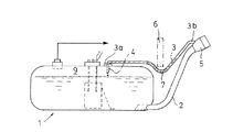
図示の実施形態による燃料タンク1は、給油管2と給油時排気管路3とを共にタンク本体容器に一体成形で備えたプラスチック製燃料タンクとして構成されている。給油時排気管路3の第1端部3aは燃料タンク1の上部排気口4に接続されており、給油時排気管路の第2端部3bは、図示しない給油ガンを受け入れるために給油管2の先端部に設けられた給油口マウスピース5内に通じている。図1に符号6で暗示的に示されているのは自動車の車体構造要素、例えば縦通材であり、本発明で解決すべき課題の原因を生じている車体に対する燃料タンク1の据付位置関係を明らかにしている。燃料タンク1が車体に対してこのような据付位置関係で配置されるため、給油時排気管路3は湾曲した経路に沿って配管され、特にその長さの約半分に亘って屈曲した肘状の下向き湾曲部を形成している。この湾曲部を本発明ではサイホン部7と称する。尚、本発明に関する記述において「サイホン」という用語は、給油時排気管路内におけるガスの貫流を妨げる液体滞留部を形成する虞のある管路湾曲部という意味で使用している。
The
燃料タンクへの給油時には、給油管2を通して燃料タンク1に流入した燃料はタンク内の上部空間にあるガスを押しのけ、この押しのけられたガスは上部排気口4から給油時排気管路3を通して給油管2の給油口マウスピース5内に送り戻され、マウスピース内で給油中の給油ガンに吸引される。その際、燃料タンク1の上部排気口4を通して液体炭化水素が伴送され、これがサイホン部7内に溜まることは不可避である。給油時排気管路3内で凝縮する燃料もサイホン部7に溜まることになる。
When fuel is supplied to the fuel tank, the fuel that has flowed into the
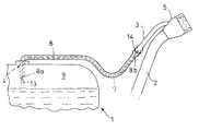
そこで、給油時排気管路3が途中のサイホン部7に滞留した液体燃料で閉塞されるのを回避するように、給油時排気管路3の内部に毛管作用で給油時排気管路内の液体燃料を吸い上げる軽量で柔らかい紐状の芯部材8が延設されている。芯部材8の横断面は、給油時排気管路3の内部横断面に比べて、排気の通流が損なわれないように比較的小断面積に選定されている。芯部材8の第1端部8aは燃料タンク1の上部補償容積空間9内に突き出されている。芯部材8の第2端部8bは保持要素10を備えており、この保持要素によって芯部材8が給油時排気管路3内に係止されている。保持要素10は本体部が保持リング11からなり、この保持リング内に芯部材8の第2端部8bが挿通されて締め付け固定されている。保持リング11には放射状に3つのスプリングアーム12が一体成形されている。各スプリングアーム12はそれぞれの先端部の係止爪が芯部材8の第2端部8b側へ寄るように傾斜しており、給油時排気管路3内に配置された状態において給油口マウスピース側で保持リング11の軸心との間に鋭角を成している。
Therefore, in order to avoid clogging of the
仕上げ処理された給油時排気管路3内に芯部材8を組み込む際には、芯部材8をその第1端部8aからマウスピース5内の給油時排気管路開口端内に挿入し、給油口マウスピース5側から供給する圧縮空気に随伴させて給油時排気管路3内に押し込むことで挿入する。
When incorporated into the finishing treated refueling exhaust passage 3 a
この圧縮空気に随伴させて押し込む際の先導補助具となるように芯部材8の第1端部8aには重錘13が取り付けられており、この重錘が芯部材8を最終的な組み込み配置位置で伸張状態にする。圧縮空気による挿入時に追従して給油時排気管路3内に引き込まれる第2端部8bは、その保持要素10が給油時排気管路3の途中に設けられている蛇腹部14内に達すると、保持要素10のスプリングアーム12が自身の弾性で復帰拡径して先端部の係止爪が蛇腹部14内の波形又はリブ部に係合するこよにより蛇腹部14に係止される。
And
1 :燃料タンク
2 :給油管
3 :給油時排気管路
3a:給油時排気管路の第1端部
3b:給油時排気管路の第2端部
4 :燃料タンク上部排気口
5 :給油口マウスピース
6 :車体構造要素
7 :サイホン部
8 :芯部材
8a:芯部材の第1端部
8b:芯部材の第2端部
9 :燃料タンク内の上部補償容積空間
10 :保持要素
11 :保持リング
12 :スプリングアーム
13 :重錘
14 :給油管の蛇腹部
DESCRIPTION OF SYMBOLS 1: Fuel tank 2: Refueling pipe 3: Exhaust pipe 3a at the time of refueling 3a: The 1st end part of the exhaust line at the time of
Claims (7)
Applications Claiming Priority (1)
| Application Number | Priority Date | Filing Date | Title |
|---|---|---|---|
| DE102005052072A DE102005052072B3 (en) | 2005-10-28 | 2005-10-28 | Fuel tank |
Publications (2)
| Publication Number | Publication Date |
|---|---|
| JP2007118942A JP2007118942A (en) | 2007-05-17 |
| JP4384652B2 true JP4384652B2 (en) | 2009-12-16 |
Family
ID=37685045
Family Applications (1)
| Application Number | Title | Priority Date | Filing Date |
|---|---|---|---|
| JP2006287354A Expired - Fee Related JP4384652B2 (en) | 2005-10-28 | 2006-10-23 | Fuel tank |
Country Status (7)
| Country | Link |
|---|---|
| EP (1) | EP1780068B1 (en) |
| JP (1) | JP4384652B2 (en) |
| KR (1) | KR100873596B1 (en) |
| CN (1) | CN100486830C (en) |
| AT (1) | ATE433389T1 (en) |
| BR (1) | BRPI0604360A (en) |
| DE (2) | DE102005052072B3 (en) |
Families Citing this family (4)
| Publication number | Priority date | Publication date | Assignee | Title |
|---|---|---|---|---|
| DE102011014713B4 (en) * | 2011-03-23 | 2016-05-19 | Audi Ag | Tank ventilation device for a motor vehicle |
| DE102011108333B4 (en) * | 2011-07-25 | 2014-11-20 | Kautex Textron Gmbh & Co. Kg | Liquid container for a motor vehicle, in particular a fuel tank |
| CN112406524A (en) * | 2020-11-13 | 2021-02-26 | 亚普汽车部件股份有限公司 | Internal and external exhaust system of plastic fuel tank and connecting method |
| CN115234408B (en) * | 2021-04-23 | 2023-09-29 | 山东垚旭节能环保科技有限公司 | Emission reduction and synergy device of gasoline car |
Family Cites Families (10)
| Publication number | Priority date | Publication date | Assignee | Title |
|---|---|---|---|---|
| US2548734A (en) * | 1947-11-05 | 1951-04-10 | Scully Signal Co | Insertable vent pipe |
| DE1904501A1 (en) * | 1969-01-30 | 1970-08-13 | Heinrich Finck | Motor vehicle equipment with a plastic tank and a tank level meter based on a purely mechanical mode of operation to avoid tank explosions |
| DE2509428A1 (en) * | 1975-03-05 | 1976-09-16 | Audi Nsu Auto Union Ag | Sintered filter in petrol tank breather pipe - allows gas transfer but prevents passage of liquids |
| DE4100388A1 (en) * | 1991-01-09 | 1992-07-16 | Karl Werz | Method of venting fuel tank - involves use of movable tube supported by float |
| US5769057A (en) * | 1995-10-09 | 1998-06-23 | Nissan Motor Co., Ltd. | Fuel tank system |
| DE60020191T2 (en) * | 1999-07-16 | 2005-10-13 | Honda Giken Kogyo K.K. | Fuel tank |
| DE10013919A1 (en) * | 2000-03-21 | 2001-09-27 | Mannesmann Vdo Ag | Venting device for a fuel tank |
| JP2002371933A (en) * | 2001-06-14 | 2002-12-26 | Honda Motor Co Ltd | Fuel tank of car |
| JP2004218501A (en) * | 2003-01-14 | 2004-08-05 | Toyota Motor Corp | Fuel vapor treatment device |
| CN2630025Y (en) * | 2003-06-02 | 2004-08-04 | 邓须柱 | Automatic air-bleed fuel tank |
-
2005
- 2005-10-28 DE DE102005052072A patent/DE102005052072B3/en not_active Expired - Fee Related
-
2006
- 2006-10-13 DE DE502006003926T patent/DE502006003926D1/en active Active
- 2006-10-13 AT AT06021556T patent/ATE433389T1/en not_active IP Right Cessation
- 2006-10-13 EP EP06021556A patent/EP1780068B1/en not_active Not-in-force
- 2006-10-23 JP JP2006287354A patent/JP4384652B2/en not_active Expired - Fee Related
- 2006-10-25 KR KR1020060103828A patent/KR100873596B1/en not_active IP Right Cessation
- 2006-10-27 CN CNB200610142838XA patent/CN100486830C/en not_active Expired - Fee Related
- 2006-10-27 BR BRPI0604360-7A patent/BRPI0604360A/en not_active IP Right Cessation
Also Published As
| Publication number | Publication date |
|---|---|
| ATE433389T1 (en) | 2009-06-15 |
| DE102005052072B3 (en) | 2007-07-12 |
| CN100486830C (en) | 2009-05-13 |
| DE502006003926D1 (en) | 2009-07-23 |
| KR20070045928A (en) | 2007-05-02 |
| EP1780068A3 (en) | 2007-08-15 |
| EP1780068B1 (en) | 2009-06-10 |
| JP2007118942A (en) | 2007-05-17 |
| BRPI0604360A (en) | 2007-08-21 |
| CN1955029A (en) | 2007-05-02 |
| EP1780068A2 (en) | 2007-05-02 |
| KR100873596B1 (en) | 2008-12-11 |
Similar Documents
| Publication | Publication Date | Title |
|---|---|---|
| JP5554344B2 (en) | Tank assembly device and vehicle with tank assembly device | |
| JPH0332411Y2 (en) | ||
| JP4384652B2 (en) | Fuel tank | |
| US20020148510A1 (en) | Fuel tank | |
| JP5352272B2 (en) | Fuel tank | |
| US20120168028A1 (en) | Oil vapor recovery type fuel dispensing gun | |
| JP4766480B2 (en) | Air intake device for canister air filter | |
| EP0616574B2 (en) | A vent device for a fuel supply pipe | |
| KR100898387B1 (en) | Motor vehicle fuel tank | |
| EP0822110B1 (en) | A filler pipe unit for the fuel tank of a motor vehicle | |
| EP1190884A3 (en) | Fuel filler pipe | |
| JP2005126042A (en) | Fuel tank system for automobile | |
| US20080149199A1 (en) | Saddle tank | |
| JP2006234131A (en) | Bellows tube | |
| US20140263312A1 (en) | Fuel theft prevention device for automobile | |
| JP2000052789A (en) | Filling device of fuel tank | |
| JP4062700B2 (en) | Master cylinder reservoir | |
| JP4406830B2 (en) | Filler pipe | |
| EP2509815B1 (en) | Arrangement for fuel supply to an engine | |
| JP6020065B2 (en) | Fuel tank | |
| CN207468188U (en) | A kind of oiling pipe assembly of fuel tank of vehicle | |
| JP5963737B2 (en) | Fuel tank system | |
| JP6127024B2 (en) | Vehicle fuel supply device | |
| RU2203190C2 (en) | Filler pipe unit for fuel tank of motorized vehicle | |
| JP7375783B2 (en) | Refueling device |
Legal Events
| Date | Code | Title | Description |
|---|---|---|---|
| A977 | Report on retrieval |
Free format text: JAPANESE INTERMEDIATE CODE: A971007 Effective date: 20090129 |
|
| A131 | Notification of reasons for refusal |
Free format text: JAPANESE INTERMEDIATE CODE: A131 Effective date: 20090204 |
|
| A601 | Written request for extension of time |
Free format text: JAPANESE INTERMEDIATE CODE: A601 Effective date: 20090501 |
|
| A602 | Written permission of extension of time |
Free format text: JAPANESE INTERMEDIATE CODE: A602 Effective date: 20090511 |
|
| A601 | Written request for extension of time |
Free format text: JAPANESE INTERMEDIATE CODE: A601 Effective date: 20090604 |
|
| A602 | Written permission of extension of time |
Free format text: JAPANESE INTERMEDIATE CODE: A602 Effective date: 20090609 |
|
| A601 | Written request for extension of time |
Free format text: JAPANESE INTERMEDIATE CODE: A601 Effective date: 20090703 |
|
| A602 | Written permission of extension of time |
Free format text: JAPANESE INTERMEDIATE CODE: A602 Effective date: 20090709 |
|
| A521 | Request for written amendment filed |
Free format text: JAPANESE INTERMEDIATE CODE: A523 Effective date: 20090804 |
|
| TRDD | Decision of grant or rejection written | ||
| A01 | Written decision to grant a patent or to grant a registration (utility model) |
Free format text: JAPANESE INTERMEDIATE CODE: A01 Effective date: 20090903 |
|
| A01 | Written decision to grant a patent or to grant a registration (utility model) |
Free format text: JAPANESE INTERMEDIATE CODE: A01 |
|
| A61 | First payment of annual fees (during grant procedure) |
Free format text: JAPANESE INTERMEDIATE CODE: A61 Effective date: 20090925 |
|
| FPAY | Renewal fee payment (event date is renewal date of database) |
Free format text: PAYMENT UNTIL: 20121002 Year of fee payment: 3 |
|
| R150 | Certificate of patent or registration of utility model |
Free format text: JAPANESE INTERMEDIATE CODE: R150 |
|
| FPAY | Renewal fee payment (event date is renewal date of database) |
Free format text: PAYMENT UNTIL: 20131002 Year of fee payment: 4 |
|
| R250 | Receipt of annual fees |
Free format text: JAPANESE INTERMEDIATE CODE: R250 |
|
| LAPS | Cancellation because of no payment of annual fees |