JP4384189B2 - refrigerator - Google Patents

refrigerator Download PDF

Info

Publication number
JP4384189B2
JP4384189B2 JP2007031033A JP2007031033A JP4384189B2 JP 4384189 B2 JP4384189 B2 JP 4384189B2 JP 2007031033 A JP2007031033 A JP 2007031033A JP 2007031033 A JP2007031033 A JP 2007031033A JP 4384189 B2 JP4384189 B2 JP 4384189B2
Authority
JP
Japan
Prior art keywords
door
opening
freezer compartment
refrigerator
drive
Prior art date
Legal status (The legal status is an assumption and is not a legal conclusion. Google has not performed a legal analysis and makes no representation as to the accuracy of the status listed.)
Expired - Fee Related
Application number
JP2007031033A
Other languages
Japanese (ja)
Other versions
JP2008196750A (en
Inventor
英樹 吉田
弘直 釜谷
信之 長安
芳輝 菊地
Current Assignee (The listed assignees may be inaccurate. Google has not performed a legal analysis and makes no representation or warranty as to the accuracy of the list.)
Hitachi Appliances Inc
Original Assignee
Hitachi Appliances Inc
Priority date (The priority date is an assumption and is not a legal conclusion. Google has not performed a legal analysis and makes no representation as to the accuracy of the date listed.)
Filing date
Publication date
Application filed by Hitachi Appliances Inc filed Critical Hitachi Appliances Inc
Priority to JP2007031033A priority Critical patent/JP4384189B2/en
Priority to CNB2007101403847A priority patent/CN100545559C/en
Publication of JP2008196750A publication Critical patent/JP2008196750A/en
Application granted granted Critical
Publication of JP4384189B2 publication Critical patent/JP4384189B2/en
Expired - Fee Related legal-status Critical Current
Anticipated expiration legal-status Critical

Links

Images

Description

本発明は、冷蔵庫に関する。   The present invention relates to a refrigerator.

従来、冷蔵庫のドアを自動的に開放させる装置として、特許文献1から6に記載の構成がある。   Conventionally, there is a configuration described in Patent Documents 1 to 6 as an apparatus for automatically opening a refrigerator door.

特許文献1には、高ギヤ比の短距離動作区間と、低ギヤ比の長距離動作区間とを備え、低ギヤ比部には過負荷防止クラッチを設け、パッキンを引き剥がす際に大きな力を発生し、その後は高速で開放する、という構成が開示されている。   Patent Document 1 includes a short-distance operation section with a high gear ratio and a long-distance operation section with a low gear ratio. An overload prevention clutch is provided in the low gear ratio section, and a large force is applied when the packing is peeled off. A configuration is disclosed that occurs and then opens at high speed.

特許文献2には、押圧部材をウォームギヤとラックによって直線運動させて、その押圧部材によって引出し扉を押し出して自動開放し、扉が開き終わると、復帰ばねで引込位置に復帰する構成が開示されている。   Patent Document 2 discloses a configuration in which a pressing member is linearly moved by a worm gear and a rack, the drawer door is pushed out automatically by the pressing member and automatically opened, and when the door is completely opened, the return spring returns to the retracted position. Yes.

特許文献3には、引出し扉を支持する支持フレーム内にタイミングベルトを設け、タイミングベルト上を摺動する自動オープンユニットを設け、自動オープンユニットは、引出しケースを押し出すスライドピンと、タイミングベルト上を動作するローラと、スライドピンとローラを駆動させるための駆動手段からなる構成が開示されている。   In Patent Document 3, a timing belt is provided in a support frame that supports a drawer door, an automatic opening unit that slides on the timing belt is provided, and the automatic opening unit operates on a timing pin and a slide pin that pushes out a drawer case. And a driving pin for driving the slide pin and the roller.

特許文献4には、ウォームギヤを用いた減速ギヤの出力段にカム装置が設けられ、このカム装置の開閉扉への当接部が円弧状であり、駆動モータへの一定時間の通電による回転動作によって、冷蔵庫本体から扉側に突出して扉を開放する構成が開示されている。   In Patent Document 4, a cam device is provided at an output stage of a reduction gear using a worm gear, and a contact portion of the cam device with an opening / closing door has an arc shape, and a rotation operation is performed by energizing a drive motor for a certain period of time. The structure which protrudes from the refrigerator main body to the door side and opens the door is disclosed.

特許文献5には、扉開放スイッチからの信号により駆動装置を介してカムを回転させることにより、カムの長径部端面が前方に突出して扉を開放する、円と楕円を組み合わせた形状または楕円形状をなすカム装置の構成が開示されている。   Patent Document 5 discloses a combination of a circle and an ellipse, or an elliptical shape in which a cam is rotated via a drive device in response to a signal from a door opening switch so that the long diameter end surface of the cam projects forward and opens the door. The structure of the cam apparatus which makes | forms is disclosed.

特許文献6には、引出し扉の後方に出力軸にカムを設けた電動機を備え、カムの回動によりフレームを押し出し、さらにカム位置検知用のマイクロスイッチを備え、マイクロスイッチの作動によりカムを所定位置に停止させる構成が開示されている。   Patent Document 6 includes an electric motor provided with a cam on the output shaft behind the drawer door, pushes the frame by rotating the cam, and further includes a micro switch for detecting the cam position. A configuration for stopping at a position is disclosed.

特開平02−157581号公報Japanese Patent Laid-Open No. 02-157581 特開2001−280827号公報Japanese Patent Laid-Open No. 2001-280827 特開2000−220957号公報JP 2000-220957 A 特開2002−257466号公報JP 2002-257466 A 特開2001−317864号公報JP 2001-317864 A 実開平1−167590号公報Japanese Utility Model Publication No. 1-167590

近年では食生活が変化してきており、毎日の食材をこまめに近隣の食品店で購入して調理する食生活から、郊外の大型スーパーマーケット等で食品を一週間分まとめて購入し、冷蔵庫に貯蔵するようなスタイルが一般化しつつある。また、冷凍食品の利用が増えたことに対応して家庭でも400リットルを超える容量の大型冷蔵庫が一般的に普及してきている。   In recent years, the eating habits have changed, and from daily eating of daily ingredients at nearby food stores, food is purchased for a week at large supermarkets in the suburbs and stored in the refrigerator. Such a style is becoming common. In response to the increase in the use of frozen foods, large refrigerators with a capacity exceeding 400 liters are generally spreading at home.

しかし、冷蔵庫の大型化に伴って収納される食品の量も増え、冷凍室や野菜室には例えば20kg以上の食品を保管するので、野菜室や冷凍室の引出し扉を開く際に要する力が大きくなってしまう。   However, as the size of the refrigerator increases, the amount of food stored increases, and for example, 20 kg or more of food is stored in the freezer compartment or vegetable compartment. Therefore, the force required to open the drawer door in the vegetable compartment or freezer compartment is increased. It gets bigger.

特に、冷蔵庫の扉には冷気もれを防止するためにマグネット吸着式のパッキンが扉の全周にわたって設けられており、扉の開き始めには、引出しレールの負荷抵抗に加え、冷蔵庫本体に吸着しているマグネットパッキンを引き剥がす力を要する。そのため、高齢者等の手指の力が弱い人にとっては、冷蔵庫の引出し扉を開く動作は過度の負担となる。   In particular, the door of the refrigerator is provided with a magnet adsorption type packing over the entire circumference of the door to prevent cold air leaks, and in addition to the load resistance of the drawer rail, it is adsorbed to the refrigerator body at the beginning of the door opening. It requires a force to peel off the magnet packing. For this reason, the operation of opening the drawer door of the refrigerator is an excessive burden for a person with weak finger strength, such as an elderly person.

また、冷蔵庫の扉を閉じる際、閉め方が不十分な所謂半ドア状態になると、冷気が外部にもれて冷却機能が失われ、省エネ効果の低下や、庫内貯蔵食品の品質劣化等の問題がおきる。さらに、冷蔵庫外の外気が庫内に侵入して結露し、庫内に水滴が付着してしまう。また、電気代が余計にかかってしまうことも問題である。   In addition, when the refrigerator door is closed, if it is in a so-called half-door state where the closing method is insufficient, the cooling air is lost to the outside, the cooling function is lost, the energy saving effect is reduced, the quality of the food stored in the warehouse is deteriorated, etc. Problems arise. Furthermore, outside air outside the refrigerator enters the inside of the cabinet and causes condensation, and water droplets adhere to the inside of the cabinet. Another problem is that the cost of electricity is excessive.

また、冷蔵庫の扉を閉じるとき、全閉状態に至る近傍、一例として開き量が残り50
mm程度にまで閉じられた際は、ばね等の力によって扉を引き込むクローザ機構を備えた構成が一般的である。
Moreover, when the door of the refrigerator is closed, the opening amount remains in the vicinity of the fully closed state, for example, 50%.
A configuration provided with a closer mechanism that pulls the door in by a force of a spring or the like when closed to about mm is common.

冷蔵庫の扉を全閉状態から開く場合、マグネットパッキンの吸着力に抗する力、クローザ機構のバネの引張り力に抗する力、引出し全体(扉、収納容器、及び収納食品を含む)を停止状態から引開ける加速力(例えば秒速200mm程度までに必要な加速力)が必要となる。すなわち、これらの合力を扉に加えて開く必要がある。そのため、扉の全閉状態から開くときが、一連の扉開動作の中で最も大きな力を要する。これを「第一の力」と称する。   When the refrigerator door is opened from the fully closed state, the force against the magnetic packing adsorption force, the force against the pulling force of the closer mechanism spring, and the entire drawer (including the door, storage container, and stored food) are stopped. Acceleration force (for example, acceleration force required up to about 200 mm per second) is required. That is, it is necessary to open these combined forces on the door. Therefore, when the door is opened from the fully closed state, the greatest force is required in a series of door opening operations. This is referred to as “first force”.

扉を10mm程度引き開けた後は、マグネットパッキンと本体との吸着が引き剥がされる。そのため、引出し動作に要する力は、クローザ機構のもつバネの引張り力に抗する力と、引出し全体を開放方向へ加速する加速力との合力である。これを「第二の力」と称する。   After opening the door about 10 mm, the adsorption between the magnet packing and the main body is peeled off. Therefore, the force required for the drawer operation is a resultant force of a force that resists the tension force of the spring of the closer mechanism and an acceleration force that accelerates the entire drawer in the opening direction. This is referred to as “second force”.

クローザ機構による扉閉鎖方向への引張り力がはたらく範囲が、一例として扉の閉鎖状態から50mmとすると、その範囲では第二の力が必要となる。   When the range in which the pulling force in the door closing direction by the closer mechanism works is 50 mm from the door closed state as an example, the second force is required in that range.

さらに開き動作を継続して扉が50mm以上開いた後は、クローザ機構は作用せず、引出しに加える力は開放方向への加速力と、引出しをスライドするためのスライドレールとの間で生じる摩擦力のみとなる。これを「第三の力」と称する。第三の力は第一の力や第二の力に比べて、僅かな力となる。ここで、50mm程度開いた時点で引出しが開放速度に達したとすれば、第三の力はスライドレールとの間で生じる摩擦力に抗する力のみで十分となる。   Furthermore, after the opening operation is continued and the door is opened more than 50 mm, the closer mechanism does not work, and the force applied to the drawer is the friction generated between the acceleration force in the opening direction and the slide rail for sliding the drawer. Only power. This is referred to as a “third force”. The third force is a slight force compared to the first force and the second force. Here, if the drawer reaches the opening speed when it is opened by about 50 mm, the third force is sufficient only to resist the frictional force generated with the slide rail.

冷蔵庫の引出し扉を開く際には、上述したように開き始めが特に重く、ある程度(一例として50mm等)開いた後は僅かな力でよい、という特性がある。   When opening the drawer door of the refrigerator, the opening is particularly heavy as described above, and after opening to a certain extent (for example, 50 mm), there is a characteristic that a slight force is sufficient.

本発明は、上記のような冷蔵庫の引出し扉を引出す際の力の特性に適合した、冷蔵庫引出し扉開閉装置を提供することを目的とする。   It is an object of the present invention to provide a refrigerator drawer door opening / closing device adapted to the characteristics of the force when pulling out the drawer door of the refrigerator as described above.

また、扉の開放速度について、マグネットパッキンを引き剥がす時は、停止状態から動き始めるため、第一の力の範囲で速度はごく小さくてよい。一方、第二、第三の力の範囲まで引出し扉を開き続けたときに、扉が次第に加速するような動作とすれば、ユーザが引出し扉を手動で引張る際の動作に近く、自然な動作となる。   Further, regarding the opening speed of the door, when the magnet packing is peeled off, the movement starts from the stop state, and therefore the speed may be very small within the range of the first force. On the other hand, when the drawer door is opened to the range of the second and third forces and the door is gradually accelerated, it is close to the action when the user manually pulls the drawer door, and it is natural. It becomes.

本発明は、さらに上記のような冷蔵庫の引出し扉を引出す際の速度の特性に適合した、冷蔵庫引出し扉開閉装置を提供することを目的とする。   Another object of the present invention is to provide a refrigerator drawer door opening / closing device adapted to the speed characteristics when the refrigerator drawer door is pulled out as described above.

また、引出し扉を開く際に扉が完全に開くまで開き力が加わり続ける構成の場合、扉の直前にユーザが立っていたり、あるいは物が置いてあったりすると、それらに引出し扉が当たった後も、開き力が加わり続けて危険である。したがって、引出し扉を開く際には、駆動力を加え続けるのではなく、開き始めの短い範囲だけ駆動力を加え、その後は駆動力の範囲で得た初速が、スライドレールのもつ摩擦力によって徐々に減速しながら停止する、所謂惰性による動作が安全である。   In addition, when opening the drawer door, if the opening force continues to be applied until the door is fully opened, if the user stands or objects are placed in front of the door, after the drawer door hits them However, it is dangerous because the opening force continues to be applied. Therefore, when the drawer door is opened, the driving force is not applied continuously, but the driving force is applied only for a short range at the beginning of opening. Thereafter, the initial speed obtained in the driving force range is gradually increased by the frictional force of the slide rail. The operation by so-called inertia which stops while decelerating is safe.

さらに、停電など扉開閉装置が動作しない状況の場合には、手動により引出しを開閉することになるので、冷蔵庫引出し扉開閉装置が、手動による開閉動作の妨げや、負荷にならない構成とすることが望ましい。   Furthermore, in the situation where the door opening and closing device does not operate, such as a power failure, the drawer is manually opened and closed, so the refrigerator drawer door opening and closing device may be configured not to interfere with the manual opening and closing operation or to become a load. desirable.

特許文献1においては、短ストロークの扉押出し手段と長ストロークの扉押出し手段とが必要であり、複雑な構成となる。   In Patent Document 1, a short stroke door extruding means and a long stroke door extruding means are required, resulting in a complicated configuration.

特許文献2においては、ウォームとラックを用いた構成を開示している。しかし、引出し扉を開く速度はラックの動作速度と一定になる。そこで、マグネットパッキン引き剥がしに要する力を出力可能にするためには、減速比を大きくする必要がある。そのため、動作速度が遅く、また、扉閉機能については備えていない。   In Patent Document 2, a configuration using a worm and a rack is disclosed. However, the opening speed of the drawer door is constant with the operation speed of the rack. Therefore, in order to be able to output the force required for peeling off the magnet packing, it is necessary to increase the reduction ratio. Therefore, the operation speed is slow and the door closing function is not provided.

特許文献3においては、引出しケースを開いた後に駆動手段を逆転させ歯車の噛み合いを外す構成が開示されている。しかし、引出しを一部だけ開いた状態で歯車の噛み合いを外す構成や動作については述べられておらず、また扉を閉じる機能は備えていない。   Patent Document 3 discloses a configuration in which after the drawer case is opened, the driving means is reversed to disengage the gears. However, it does not describe a configuration or operation for disengaging the gears with only a part of the drawer open, and does not have a function of closing the door.

特許文献4、特許文献5、特許文献6においては、円弧状または楕円形状をなす回転自在なカムを備え、扉開放スイッチからの信号を受けるとカムを回転させて、カムの長径部端面が前方に突出することで扉を開放するカム装置が開示されている。しかし、この構成では、カムが回転した際の扉の開き量は、カムの回転に伴うカム半径の変化分のみである。よって、扉開方向に与えられる速度は小さくなり、扉の開き量を大きくすることには限界がある。   In Patent Document 4, Patent Document 5, and Patent Document 6, a rotatable cam having an arc shape or an elliptical shape is provided, and when a signal from the door opening switch is received, the cam is rotated so that the end surface of the long diameter portion of the cam is forward. The cam apparatus which opens a door by protruding is disclosed. However, in this configuration, the opening amount of the door when the cam rotates is only the change in the cam radius accompanying the rotation of the cam. Therefore, the speed given in the door opening direction is reduced, and there is a limit to increasing the door opening amount.

上記課題を解決するために、本発明の目的は、冷蔵庫の引出し扉の開き力を低減して軽快に扉を開放でき、かつ所謂半ドア状態から自動的に扉を閉鎖して省エネ効果を向上できる冷蔵庫の引出し扉開閉装置を提供することである。   In order to solve the above problems, the object of the present invention is to reduce the opening force of the drawer door of the refrigerator so that the door can be opened easily, and the door is automatically closed from the so-called half-door state to improve the energy saving effect. It is to provide a drawer door opening and closing device for a refrigerator.

上記目的を達成する為に、本発明の態様の冷蔵庫は、冷蔵庫本体に区画形成された貯蔵室と、前記貯蔵室に設けられ開閉可能な引出し扉と、前記貯蔵室に設けられ前記引出し扉を開閉させる駆動手段と、前記駆動手段にて回転可能であり、且つ回転方向に向かって回転中心からの距離を除々に変化させた位置に複数の駆動伝達部材が設けられた回転部材と、前記引出し扉又は該引出し扉とともに前後方向に引出すことができる収納部の下面に設けられ、且つ前記駆動伝達部材から動力が伝達されて前記回転部材の回転運動を直線運動に変換させる連結部材と、前記引出し扉が閉鎖されていることを検知する扉閉検知手段を備え、前記扉閉検知手段が前記引出し扉が閉鎖状態であることを検知するまで、所定回数、前記駆動伝達部材が前記連結部材に当接するように前記回転部材を回転駆動させることを特徴とする扉駆動装置を備えたことを特徴とする。 In order to achieve the above object, a refrigerator according to an aspect of the present invention includes a storage compartment defined in a refrigerator main body, a drawer door provided in the storage compartment and openable and closable, and a drawer door provided in the storage compartment. A driving means that opens and closes, a rotating member that is rotatable by the driving means, and that is provided with a plurality of drive transmission members at positions where the distance from the rotation center is gradually changed in the rotation direction; and the drawer A connecting member that is provided on the lower surface of the storage unit that can be pulled out in the front-rear direction together with the door or the drawer door, and that transmits power from the drive transmission member and converts the rotational motion of the rotating member into linear motion; and the drawer comprising a Tobira閉detection means for detecting that the door is closed, before Kitobira閉to the detection means detects that the drawer door is closed, a predetermined number of times, the drive transmission member is the connecting Characterized by comprising a door driving device, characterized in that said rotary member is rotated so as to abut against the wood.

また、前記扉閉検知手段が前記引出し扉が閉鎖状態であることを検知するまで、前記駆動伝達部材が前記連結部材に当接するように前記回転部材を所定時間回転駆動させて、前記駆動伝達部材が前記連結部材と離反するように前記回転部材を所定位置まで回転駆動させることを所定回数繰り返す扉駆動装置を備えたことを特徴とする。 Further, until the door closing detection means detects that the drawer door is in a closed state, the drive transmission member is rotated for a predetermined time so that the drive transmission member abuts on the connecting member , and the drive transmission member And a door driving device that repeats a predetermined number of times to rotate the rotating member to a predetermined position so as to be separated from the connecting member .

また、前記回転部材の回転位置を検知する回転検知手段を備え、前記回転検知手段が前記回転部材が所定位置にあることを検知するまで、前記駆動伝達部材が前記連結部材から離反する方向に前記回転部材を回転駆動させることを特徴とする扉駆動装置を備えたことを特徴とする。 In addition, rotation detection means for detecting the rotation position of the rotation member is provided, and the drive transmission member moves away from the connection member until the rotation detection means detects that the rotation member is at a predetermined position. A door driving device characterized in that the rotating member is driven to rotate is provided.

また、扉が開放していることを報知する報知手段を備え、前記扉閉検知手段が前記引出し扉が閉鎖状態であることを検知するまで、前記駆動伝達部材が前記連結部材に当接するように前記回転部材を所定時間回転駆動させて、前記駆動伝達部材が前記連結部材と離反するように前記回転部材を所定位置まで回転駆動させることを所定回数繰り返して、報知手段を作動させることを特徴とする扉駆動装置を備えたことを特徴とする。 In addition, an informing means for informing that the door is open is provided so that the drive transmission member abuts on the connecting member until the door closing detecting means detects that the drawer door is in a closed state. And rotating the rotating member for a predetermined time to rotate the rotating member to a predetermined position so that the drive transmission member is separated from the connecting member, and repeating the predetermined number of times to operate the notifying means. A door drive device is provided.

また、貯蔵室の底壁に凹形状に設けられた凹部と、前記凹部に配設され上方が開口した下ケースと、前記下ケースの開口を閉鎖するように下ケースと接合される上ケースとを備え、前記上ケースにはリード線引出し部が設けられ、前記上ケースと前記下ケースとで形成される空間に前記駆動装置が配設され、前記上ケースと前記下ケースの接合部は貯蔵室の底壁よりも上方にある扉駆動装置を備えたことを特徴とする。   A concave portion provided in a concave shape on the bottom wall of the storage chamber; a lower case disposed in the concave portion and opened upward; an upper case joined to the lower case so as to close the opening of the lower case; The upper case is provided with a lead wire lead-out portion, the driving device is disposed in a space formed by the upper case and the lower case, and the joint between the upper case and the lower case is stored A door driving device is provided above the bottom wall of the chamber.

また、前記下ケース内には上方に延伸した仕切壁を有し、前記仕切壁は前記駆動装置を囲繞するように配設されることを特徴とすることにより、冷蔵庫の引出し扉の開き力を低減して電動で軽快に引出し扉を開放することを可能にするとともに、所謂、半ドア状態から自動的に電動で引出し扉を閉鎖して省エネ効果を向上できる。   Further, the lower case has a partition wall extending upward, and the partition wall is disposed so as to surround the driving device, thereby reducing an opening force of the drawer door of the refrigerator. It is possible to reduce the electric power and open the drawer door easily and electrically, and from the so-called half-door state, the drawer door can be automatically and electrically closed to improve the energy saving effect.

また、物などが挟まり連結部材の進行を阻止する事態となった場合には、使用者は警報で半ドア状態を回避することが出来、省エネ効果が得られる冷蔵庫を提供できる。   In addition, when an object or the like is caught and the connection member is prevented from progressing, the user can avoid the half-door state by an alarm, and can provide a refrigerator that can save energy.

また、貯蔵室底面に水が溜まるような事故が発生しても駆動手段が設けられたケース内に水が浸入し損傷することを防止できる。   Further, even if an accident occurs in which water accumulates on the bottom surface of the storage chamber, water can be prevented from entering and being damaged in the case provided with the driving means.

本発明によれば、冷蔵庫の引出し扉の開き力を低減して軽快に扉を開放でき、かつ所謂半ドア状態から扉を閉鎖して、省エネ効果および信頼性を向上できる冷蔵庫を提供するものである。   According to the present invention, there is provided a refrigerator that can open the door lightly by reducing the opening force of the drawer door of the refrigerator and can improve the energy saving effect and reliability by closing the door from a so-called half-door state. is there.

本発明の実施の形態について、以下図面に基づいて説明する。   Embodiments of the present invention will be described below with reference to the drawings.

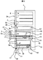
(冷蔵庫の全体構成)図1は本発明による冷蔵庫の斜視図であり、図2は縦断面図である。図1および図2において、冷蔵庫本体1は複数の収納室に分割されており、最上部は冷蔵室2であり、その前面には冷蔵室扉2aが設けられている。図1は、一例として左右両側に開く所謂フレンチドアを示している。冷蔵室2の下方は左右に分割区画された収納室となっており、例えばその一方は機能切り替え室3となっており、もう一方は図示しない自動製氷装置によって製作された氷を貯蔵する製氷室4となっている。そして、夫々の前面には切り替え室扉3a、製氷室扉が設けられている。さらにその下方には、手前に引出して開放可能な冷凍室扉5aを前面に備えた、冷凍室5となっている。冷凍室5の下方は、同様に引出し可能な野菜室扉6aを前面に備えた、野菜室6となっている。   (Overall structure of refrigerator) FIG. 1 is a perspective view of a refrigerator according to the present invention, and FIG. 2 is a longitudinal sectional view thereof. 1 and 2, the refrigerator main body 1 is divided into a plurality of storage rooms, the uppermost part is a refrigerator compartment 2, and a refrigerator compartment door 2a is provided on the front surface thereof. FIG. 1 shows a so-called French door that opens on both the left and right sides as an example. Below the refrigerating room 2 is a storage room divided into left and right parts, for example, one of which is a function switching room 3 and the other is an ice making room for storing ice produced by an automatic ice making device (not shown). 4 A switching chamber door 3a and an ice making chamber door are provided on the front of each. Further below that, there is a freezer compartment 5 provided with a freezer compartment door 5a that can be pulled out and opened forward. Below the freezer compartment 5 is a vegetable compartment 6 having a vegetable compartment door 6a that can be similarly drawn out on the front surface.

冷蔵室の扉には操作表示部7が備えられており、冷凍室の開スイッチ8aと野菜室の開スイッチ8bとが備えられている。ユーザが前記のスイッチを押して引出しの開動作を指示できる構成である。ここで、冷凍室5が野菜室6より上方に設けられている場合には、冷凍室の開スイッチ8aを野菜室の開スイッチ8bの上方に設けるのがよい。すなわち、扉の位置関係と同様に設けておけば、開スイッチ8の操作性が向上し好適である。   An operation display section 7 is provided on the door of the refrigerator compartment, and an open switch 8a for the freezer compartment and an open switch 8b for the vegetable compartment are provided. In this configuration, the user can instruct the opening operation of the drawer by pressing the switch. Here, when the freezer compartment 5 is provided above the vegetable compartment 6, the open switch 8a of the freezer compartment is preferably provided above the open switch 8b of the vegetable compartment. That is, it is preferable to provide the same as the positional relationship of the doors because the operability of the open switch 8 is improved.

(扉自動開閉機構)以下、冷凍室5を例に扉開閉装置10について説明する。なお、以下の説明は、野菜室6の扉開閉装置10においても、同様である。   (Automatic Door Opening / Closing Mechanism) The door opening / closing device 10 will be described below using the freezer compartment 5 as an example. In addition, the following description is the same also in the door opening / closing apparatus 10 of the vegetable compartment 6. FIG.

冷凍室5の目前面の扉体5aと、食品を収納する容器12は、容器12の左右に設けられたスライドレール11によって手前に引出し自在に支持されている。スライドレール
12の奥側には前記冷凍室5を閉鎖方向に引き込むクローザ13(閉じ付勢手段)が設けられている。これにより、一旦開いた冷凍室5を閉じる際、例えば開き量が40mm以下のとき、図示しないばね力にて奥側に引き込むように付勢して、冷凍室5の全周に設けられたマグネットパッキン14が、冷蔵庫本体1と吸着するまで冷凍室5を閉じる動作を補助する。
The door 5a in front of the freezer compartment 5 and the container 12 for storing food are supported by slide rails 11 provided on the left and right sides of the container 12 so as to be drawn out toward the front. A closer 13 (closing urging means) for pulling the freezer compartment 5 in the closing direction is provided on the back side of the slide rail 12. Thereby, when closing the freezer compartment 5 once opened, for example, when the opening amount is 40 mm or less, a magnet provided on the entire circumference of the freezer compartment 5 is energized so as to be pulled in by a spring force (not shown). The operation of closing the freezer compartment 5 is assisted until the packing 14 is adsorbed to the refrigerator body 1.

冷凍室5の内部には扉開閉機構10が設けられている。扉開閉装置10は、冷蔵庫本体1に設けられた駆動機構15と、容器12の奥側下面に設けられた連結板16からなる。駆動機構15は、駆動源であるモータと、モータの回転を減速する減速機構を備える。この駆動機構15から連結板16に対して、スライドレール11における移動方向の力が加えられることで、冷凍室5の扉5aが開閉される。冷凍室5の正面側にはドア検知17が設けられており、冷凍室5が閉鎖されているか、あるいは冷凍室5の開き量が、所定量
(後述する、開き量35)以内であるか否かを検出して、制御回路に信号を送る。
A door opening / closing mechanism 10 is provided inside the freezer compartment 5. The door opening / closing device 10 includes a drive mechanism 15 provided in the refrigerator main body 1 and a connecting plate 16 provided on the bottom side of the container 12. The drive mechanism 15 includes a motor that is a drive source and a speed reduction mechanism that reduces the rotation of the motor. By applying a force in the moving direction of the slide rail 11 to the connecting plate 16 from the drive mechanism 15, the door 5 a of the freezer compartment 5 is opened and closed. A door detection 17 is provided on the front side of the freezer compartment 5, and the freezer compartment 5 is closed or whether the open amount of the freezer compartment 5 is within a predetermined amount (opening amount 35 described later). Is detected and a signal is sent to the control circuit.

(駆動伝達部材)次に、駆動機構15と連結板16とを備えた扉開閉装置10の構成について、図3から図5を用いて説明する。ここで、扉開閉装置10は冷凍室5に設けられているものとして説明する。なお、野菜室6の扉開閉装置10も同様の構成である。   (Drive transmission member) Next, the structure of the door opening and closing apparatus 10 provided with the drive mechanism 15 and the connecting plate 16 will be described with reference to FIGS. Here, the door opening and closing device 10 will be described as being provided in the freezer compartment 5. In addition, the door opening / closing apparatus 10 of the vegetable compartment 6 is also the same structure.

図3は駆動機構15と連結板16とを備えた扉開閉装置10を、図2の上方からみた平面図である。図4と図5は駆動機構15の内部構成の一例を示す斜視図である。   FIG. 3 is a plan view of the door opening / closing device 10 including the drive mechanism 15 and the connecting plate 16 as viewed from above in FIG. 4 and 5 are perspective views showing an example of the internal configuration of the drive mechanism 15. FIG.

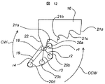
駆動機構15においては、回転出力軸である駆動軸18の周りに回転自在に回転部材である回転板19が軸支されており、回転板19には駆動伝達部材である駆動ピンが備えられている。本実施例においては、回転板19に凸状部材である駆動ピンが略円周上に3本設けられている。駆動軸18からの距離r1に第一の駆動ピン20a、距離r2に第二の駆動ピン20b、距離r3に第三の駆動ピン20cが設けられている。それぞれの駆動ピンは円筒形状をなし、かつ駆動ピンの中心軸が駆動軸18の回転中心軸と略平行となるように回転板19に立設している。ここで、r1<r2<r3とする。   In the drive mechanism 15, a rotary plate 19 that is a rotary member is rotatably supported around a drive shaft 18 that is a rotary output shaft, and the rotary plate 19 is provided with a drive pin that is a drive transmission member. Yes. In this embodiment, the rotary plate 19 is provided with three drive pins, which are convex members, on a substantially circumference. A first drive pin 20a is provided at a distance r1 from the drive shaft 18, a second drive pin 20b is provided at a distance r2, and a third drive pin 20c is provided at a distance r3. Each drive pin has a cylindrical shape, and is erected on the rotating plate 19 so that the center axis of the drive pin is substantially parallel to the rotation center axis of the drive shaft 18. Here, r1 <r2 <r3.

本実施例において回転板19は、冷凍室5を開放する際には矢印CCW方向(図3においては、反時計回り)に回転する。連結板16は冷凍室5の引出し扉と連動して引出されるように設けられているので、スライドレール11に沿って矢印23方向に移動自在である。なお、図3は、左側を冷蔵庫本体の正面側としており、連結板16が左方向に移動することで冷凍室5は開く。   In this embodiment, the rotating plate 19 rotates in the arrow CCW direction (counterclockwise in FIG. 3) when the freezer compartment 5 is opened. Since the connecting plate 16 is provided so as to be pulled out in conjunction with the drawer door of the freezer compartment 5, the connecting plate 16 is movable along the slide rail 11 in the direction of the arrow 23. In FIG. 3, the left side is the front side of the refrigerator body, and the freezer compartment 5 is opened when the connecting plate 16 moves leftward.

連結板16には、冷凍室5を開放する際に第一の駆動ピン20aが接する第一の受け面21a、第二の駆動ピン20bが接する第二の受け面21b、第三の駆動ピン20cが接する第三の受け面21c、とが備えられている。受け面は、連結板16の端部に夫々C字形状に設けられ、かつこれら受け面が階段状に連なって構成されている。なお、駆動ピンと受け面21との動作時の詳細な説明は後述する。   The connecting plate 16 has a first receiving surface 21a with which the first driving pin 20a contacts when the freezer compartment 5 is opened, a second receiving surface 21b with which the second driving pin 20b contacts, and a third driving pin 20c. And a third receiving surface 21c in contact with each other. The receiving surfaces are each provided in a C-shape at the end of the connecting plate 16, and these receiving surfaces are configured in a staircase pattern. A detailed description of the operation of the drive pin and the receiving surface 21 will be described later.

図4および図5において、モータ24の回転軸にはモータピニオン25が設けられており、アイドラ26と噛み合って減速される。アイドラ26とアイドラピニオン27は一体で回転し、アイドラピニオン27はアイドラ28と噛み合っている。アイドラ28とアイドラピニオン29は一体で回転し、アイドラピニオン29は駆動ギヤ30と噛み合って減速される。駆動軸18と駆動ギヤ30は連結されており、このようなギヤの構成によりモータ24の回転速度は、例えば1/100程度に減速され、駆動軸18に設けられた回転板19を回転させる。本実施例においては、アイドラ28とアイドラピニオン29との間にはトルク制限手段31が設けられる。これにより、回転板16に過大な外力が加えられた場合、トルク制限手段31が介在してアイドラ28とアイドラピニオン29とが互いに滑るため、駆動機構15の破損を防止できる。また、駆動軸18には回転検知手段32を設けて駆動軸18の回転位置を検出できる構成としている。このような回転検知手段32として、軸の回転によってその抵抗値が変化する可変抵抗器がある。   4 and 5, a motor pinion 25 is provided on the rotating shaft of the motor 24 and meshes with the idler 26 to be decelerated. The idler 26 and the idler pinion 27 rotate together, and the idler pinion 27 meshes with the idler 28. The idler 28 and idler pinion 29 rotate together, and the idler pinion 29 meshes with the drive gear 30 and is decelerated. The drive shaft 18 and the drive gear 30 are connected. With such a gear configuration, the rotational speed of the motor 24 is reduced to, for example, about 1/100, and the rotating plate 19 provided on the drive shaft 18 is rotated. In this embodiment, a torque limiting means 31 is provided between the idler 28 and the idler pinion 29. Thereby, when an excessive external force is applied to the rotating plate 16, the idler 28 and the idler pinion 29 slide with each other with the torque limiting means 31 interposed therebetween, so that the drive mechanism 15 can be prevented from being damaged. Further, the drive shaft 18 is provided with a rotation detection means 32 so that the rotational position of the drive shaft 18 can be detected. As such a rotation detecting means 32, there is a variable resistor whose resistance value changes with rotation of the shaft.

(扉開放動作)次に、本発明による扉開閉装置10により冷凍室扉5aを開く際の動作について、図6にて説明する。図6は本発明による扉開閉装置10が冷凍室5を開放する際の動作を示す図である。(a)は冷凍室5が閉じている状態を示しており、(b)(c)(d)(e)の順に動作することで、冷凍室扉5aを開放する動作を示している。回転板19は駆動軸18のまわりに回転自在に設けられ、連結板16は図示左右方向に移動自在に支持されている。連結板16は冷凍室の容器12の下方に備えられており、連結板16の左方向への動きが冷凍室5における開き動作を示している。ここで、冷凍室5が閉じた状態の連結板16の位置を示す基準線を、引き込み位置34として示す。   (Door Opening Operation) Next, the operation when the freezer door 5a is opened by the door opening and closing device 10 according to the present invention will be described with reference to FIG. FIG. 6 is a view showing an operation when the door opening / closing device 10 according to the present invention opens the freezer compartment 5. (A) has shown the state which the freezer compartment 5 has closed, and has shown operation | movement which open | releases the freezer compartment door 5a by operate | moving in order of (b) (c) (d) (e). The rotary plate 19 is rotatably provided around the drive shaft 18, and the connecting plate 16 is supported so as to be movable in the horizontal direction in the figure. The connecting plate 16 is provided below the container 12 in the freezer compartment, and the leftward movement of the connecting plate 16 indicates the opening operation in the freezer compartment 5. Here, a reference line indicating the position of the connecting plate 16 in a state in which the freezer compartment 5 is closed is shown as a drawing position 34.

(b)の状態において、回転板19は矢印CCW方向(図6においては反時計回り)に回転し、第一の駆動ピン20aが第一の受け面21aと接し、連結板16に対して矢印
23a方向に付勢する。このとき、第一の駆動ピン20aは駆動軸18から図3に示した距離r1の位置にあるので、第一の駆動ピン20aから連結板16に伝えられる力は、駆動軸18に加わるトルクをTとすれば、T/r1となる。この力を、冷凍室5のマグネットパッキンを引き剥がす力に抗する力と、クローザ13による引込力に抗する力と、冷凍室5の自重および収納された食品の質量を加速する力との合力以上となるように設定することで、マグネットパッキンの吸着を引き剥がして、連結板16は冷凍室5とともに図示左方向に移動して、冷凍室5は開き始める。
In the state of (b), the rotating plate 19 rotates in the direction of the arrow CCW (counterclockwise in FIG. 6), the first drive pin 20a is in contact with the first receiving surface 21a, and the arrow with respect to the connecting plate 16 is reached. Energize in the 23a direction. At this time, since the first drive pin 20a is located at the distance r1 shown in FIG. 3 from the drive shaft 18, the force transmitted from the first drive pin 20a to the connecting plate 16 is the torque applied to the drive shaft 18. If T, then T / r1. The resultant force of the force that resists the force that peels off the magnetic packing in the freezer compartment 5, the force that resists the pull-in force by the closer 13, and the force that accelerates the weight of the freezer compartment 5 and the mass of the stored food. By setting as described above, the adsorption of the magnet packing is peeled off, the connecting plate 16 moves in the left direction in the drawing together with the freezer compartment 5, and the freezer compartment 5 starts to open.

さらに回転板19がCCW方向に回転した(c)の状態においては、第二の駆動ピン
20bが第二の受け面21bと接し、第一の駆動ピン20aは第一の受け面21aからは離反する。すなわち、第二の駆動ピン20bは駆動軸18から図3に示した距離r2の位置にあり、かつr2>r1である。これにより、第一の駆動ピン20aよりも第二の駆動ピン20bが回転中心である駆動軸18から離れた距離に位置するため、周速が速い。そのため、第二の駆動ピン20bが第二の受け面21bと当接した後は、第一の駆動ピン
20aは第一の受け面21aからは離反するのである。この状態において、第二の駆動ピン20bは第二の受け面21bに接して、矢印23bの力を与える。このとき、第二の駆動ピン20bは駆動軸18から図3に示した距離r2の位置にあるので、第二の駆動ピン20bから第二の受け面21bを介して連結板16に伝えられる力は、駆動軸18に加わるトルクをTとすれば、T/r2となる。この力は、図6(b)の状態で第一の駆動ピン20aが連結板16に加える矢印23a方向の力よりも小となる。マグネットパッキンは既に引き剥がされているので、このときに加わる力はクローザ13による引張り力に抗する力と、冷凍室5の自重および収納された食品の質量をさらに加速する力の合力よりも大なるように設定すればよい。連結板16は冷凍室5と共にさらに図示左方向に移動して、冷凍室5の開き動作を継続する。
Further, in the state (c) in which the rotating plate 19 is rotated in the CCW direction, the second driving pin 20b is in contact with the second receiving surface 21b, and the first driving pin 20a is separated from the first receiving surface 21a. To do. That is, the second drive pin 20b is located at the distance r2 shown in FIG. 3 from the drive shaft 18, and r2> r1. Thereby, since the 2nd drive pin 20b is located in the distance away from the drive shaft 18 which is a rotation center rather than the 1st drive pin 20a, a circumferential speed is quick. For this reason, after the second drive pin 20b comes into contact with the second receiving surface 21b, the first drive pin 20a is separated from the first receiving surface 21a. In this state, the second drive pin 20b is in contact with the second receiving surface 21b and applies a force indicated by an arrow 23b. At this time, since the second drive pin 20b is located at the distance r2 shown in FIG. 3 from the drive shaft 18, the force transmitted from the second drive pin 20b to the connecting plate 16 via the second receiving surface 21b. Is T / r 2, where T is the torque applied to the drive shaft 18. This force is smaller than the force in the direction of the arrow 23a applied by the first drive pin 20a to the connecting plate 16 in the state of FIG. Since the magnet packing has already been peeled off, the force applied at this time is larger than the resultant force of the force that resists the pulling force of the closer 13 and the force that further accelerates the weight of the freezer compartment 5 and the mass of the stored food. What is necessary is just to set. The connecting plate 16 further moves in the left direction in the drawing together with the freezer compartment 5 and continues the opening operation of the freezer compartment 5.

さらに回転板19がCCW方向に回転した(d)の状態においては、第三の駆動ピン
20cが第三の受け面21cと接し、第二の駆動ピン20bは第二の受け面21bから離反する。すなわち、第三の駆動ピン20cは駆動軸18から図3に示した距離r3の位置にあり、かつr3>r2である。これにより、第二の駆動ピン20bよりも第三の駆動ピン20cの方が回転中心である駆動軸18からの距離が離れているので、周速が速い。そのため、第三の駆動ピン20cが第三の受け面21cと当接した後は、第二の駆動ピン
20bは第二の受け面21bからは離反するのである。この状態において、第三の駆動ピン20cは第三の受け面21cに接して、矢印23cの力を与える。このとき、第三の駆動ピン20cは駆動軸18から図3に示した距離r3の位置にあるので、第三の駆動ピン20cから第三の受け面21cを介して連結板16に伝えられる力は、駆動軸18に加わるトルクをTとすれば、T/r3となる。この力は図6(c)の状態で第二の駆動ピン
20bにより連結板16に加える矢印23b方向の力よりもさらに小となる。冷凍室5は既に矢印23cの扉開放方向に移動しているので、冷凍室5は容器と収納された食品も含めた自重と速度に応じた運動量をもっている。その運動量と第三の駆動ピン20cから連結板16の第三の受け面21cに伝達される力とによって、クローザ13による引張り力に抗して開き動作を継続することができる。
Further, in the state (d) in which the rotating plate 19 is rotated in the CCW direction, the third drive pin 20c is in contact with the third receiving surface 21c, and the second drive pin 20b is separated from the second receiving surface 21b. . That is, the third drive pin 20c is located at the distance r3 shown in FIG. 3 from the drive shaft 18, and r3> r2. Thereby, since the distance from the drive shaft 18 which is the rotation center of the 3rd drive pin 20c is separated from the 2nd drive pin 20b, a peripheral speed is quick. Therefore, after the third drive pin 20c comes into contact with the third receiving surface 21c, the second drive pin 20b separates from the second receiving surface 21b. In this state, the third drive pin 20c is in contact with the third receiving surface 21c and applies a force indicated by an arrow 23c. At this time, since the third drive pin 20c is located at the distance r3 shown in FIG. 3 from the drive shaft 18, the force transmitted from the third drive pin 20c to the connecting plate 16 via the third receiving surface 21c. Is T / r3, where T is the torque applied to the drive shaft 18. This force is even smaller than the force in the direction of the arrow 23b applied to the connecting plate 16 by the second drive pin 20b in the state of FIG. Since the freezer compartment 5 has already moved in the door opening direction indicated by the arrow 23c, the freezer compartment 5 has a momentum corresponding to its own weight and speed including the container and the stored food. Due to the momentum and the force transmitted from the third drive pin 20 c to the third receiving surface 21 c of the connecting plate 16, the opening operation can be continued against the pulling force by the closer 13.

さらに回転板19がCCW方向に回転した(e)の状態においては、第三の駆動ピン
20cが第三の受け面21cからほぼ離反する状態を示している。図6(a)の状態から図6(e)の状態に至るまでの連結板16の移動量33の範囲は、連結板16が駆動ピン20から力を受ける範囲、すなわち開き駆動範囲ということになる。ここで、この連結板16の移動量33は、クローザ13による引込量である閉じ付勢範囲よりも、大きくなるように設定すると好適である。すなわち、閉じ付勢範囲(クローザ13による引き込みストローク)が40mmの場合、連結板16の移動量33が一例として50mmであれば、開動作直後にクローザ13がはたらいて冷凍室5が閉じてしまうことを防止できる。
Further, in the state (e) in which the rotary plate 19 is rotated in the CCW direction, the third drive pin 20c is substantially separated from the third receiving surface 21c. The range of the movement amount 33 of the connecting plate 16 from the state of FIG. 6A to the state of FIG. 6E is a range where the connecting plate 16 receives a force from the drive pin 20, that is, an open drive range. Become. Here, it is preferable that the moving amount 33 of the connecting plate 16 is set to be larger than the closing urging range which is the pulling amount by the closer 13. That is, when the closing biasing range (retraction stroke by the closer 13) is 40 mm, if the moving amount 33 of the connecting plate 16 is 50 mm as an example, the closer 13 is activated immediately after the opening operation and the freezer compartment 5 is closed. Can be prevented.

ただし、連結板16が図6(e)の移動量33よりも左方に多く移動すると、連結板
16は、もはや駆動ピンから駆動力は受けない。しかし、冷凍室5全体は図6(a)から(e)の動作によって、矢印23d方向への速度を持っている。そのため、スライドレール11のもつ摩擦負荷によって減速して停止するまでは、開き動作は継続される。このように動作するので、冷凍室5の開き量は連結板16の移動量33よりも大きくなる。
However, if the connecting plate 16 moves more to the left than the movement amount 33 in FIG. 6E, the connecting plate 16 no longer receives the driving force from the driving pin. However, the entire freezer compartment 5 has a speed in the direction of the arrow 23d by the operations shown in FIGS. 6 (a) to 6 (e). Therefore, the opening operation is continued until it is decelerated by the friction load of the slide rail 11 and stopped. Since it operates in this way, the opening amount of the freezer compartment 5 becomes larger than the moving amount 33 of the connecting plate 16.

上記説明したように、冷凍室5の開き動作時には開き方向への駆動力を加え続けるのではなく、開き始めの短い範囲だけ駆動力を加え、その後は駆動力付与範囲で得た移動速度が、スライドレールのもつ摩擦力によって徐々に減速して停止する動作となる。これにより、扉の直前にユーザが立っていた場合、あるいは物が置いてあった場合に、冷凍室扉
5aが当たったとしても、扉開閉機構10からの開き方向への力は、もはや加わっていないので安全である。
As described above, during the opening operation of the freezer compartment 5, the driving force in the opening direction is not continuously applied, but the driving force is applied only in a short range at the beginning of opening, and then the moving speed obtained in the driving force application range is The operation is to gradually decelerate and stop by the frictional force of the slide rail. As a result, when the user stands immediately before the door or when an object is placed, the force in the opening direction from the door opening / closing mechanism 10 is no longer applied even if the freezer compartment door 5a hits. It is safe because it is not.

以上説明したように、冷凍室5を閉鎖状態から開き始める際、駆動軸18のもっとも近傍に配置された第一の駆動ピン20aが連結板16を押し出すことにより、低速で大きな力(第一の力)を発する。これにより、マグネットパッキンを引き剥がす。   As described above, when the freezer compartment 5 starts to be opened from the closed state, the first drive pin 20a disposed closest to the drive shaft 18 pushes out the connecting plate 16, so that a large force (first Force). Thereby, the magnet packing is peeled off.

次いで、第一の駆動ピン20aよりも遠方に設けられた第二の駆動ピン20bが連結板16を押し出すことにより、中程度の速度で中程度の力(第二の力)を発する。これにより、クローザ13の引込力に抗する開き動作を継続して冷凍室5を加速する。   Next, the second drive pin 20b provided farther than the first drive pin 20a pushes the connecting plate 16 to generate a medium force (second force) at a medium speed. Thereby, the opening operation | movement which resists the drawing-in force of the closer 13 is continued, and the freezer compartment 5 is accelerated.

さらに、第二の駆動ピン20bよりも駆動軸18から遠方に設けられた第三の駆動ピン20cが連結板16を押し出すことにより、高速で小さな力(第三の力)を発する。これにより、冷凍室5をさらに加速して、冷凍室5の開き動作を確実に行うことができる。   Further, the third drive pin 20c provided farther from the drive shaft 18 than the second drive pin 20b pushes the connecting plate 16 to generate a small force (third force) at high speed. Thereby, the freezer compartment 5 can be further accelerated and the freezer compartment 5 can be opened reliably.

本発明の構成は、駆動軸18と駆動ピンを結ぶ直線と、冷凍室5の開き方向23の直線とが略直交する位置で、連結板16に接して駆動力を与える。そのため、駆動ピンの速度は、回転板19の回転速度と、駆動軸18から駆動ピンまでの距離に比例する。   In the configuration of the present invention, a driving force is applied to the connecting plate 16 at a position where a straight line connecting the driving shaft 18 and the driving pin and a straight line in the opening direction 23 of the freezer compartment 5 are substantially orthogonal to each other. Therefore, the speed of the drive pin is proportional to the rotation speed of the rotating plate 19 and the distance from the drive shaft 18 to the drive pin.

従来技術の扉の押し出し距離は、カムの回転中心から扉部の接点までにおける、半径の変化分のみであった。しかし、本構成は扉を押し出す速度を高速化できるため、開き始めの短い範囲だけ駆動力を加え、その後は駆動力の範囲で得た開き速度が、スライドレールのもつ摩擦力によって徐々に減速しながら停止する動作を実現できる。   In the prior art, the push-out distance of the door was only the change in radius from the rotation center of the cam to the contact point of the door. However, since this configuration can increase the speed at which the door is pushed out, a driving force is applied only in the short opening range, and then the opening speed obtained in the driving force range is gradually reduced by the frictional force of the slide rail. The operation to stop can be realized.

上記の動作により冷凍室5が開放された後、回転板19はさらにCCW方向への回転を継続し、図6(a)の状態に至って回転を停止する。なお、この際に連結板16は図6
(a)に示す位置ではなく、冷凍室5は開いているので図示左方に移動した状態である。
After the freezer compartment 5 is opened by the above operation, the rotating plate 19 further continues to rotate in the CCW direction, reaches the state of FIG. 6A and stops rotating. At this time, the connecting plate 16 is shown in FIG.
Instead of the position shown in (a), the freezer compartment 5 is open so that it has moved to the left in the figure.

本発明による扉開閉装置においては、回転板19は冷凍室5の開き動作を行った後に、同一方向への回転を継続し、一回転して冷凍室5を閉じた際の状態、すなわち図8にて説明した原点範囲に戻る。そのため、原点範囲への復帰を高速化できる。仮に回転板19が一方向への回転ではなく、冷凍室5の開き動作を行った後、一端停止してから逆方向に回転して原点範囲に復帰する構成の場合、本構成に比べて、原点範囲に戻るまでに時間がかかる。   In the door opening and closing apparatus according to the present invention, the rotating plate 19 continues to rotate in the same direction after the opening operation of the freezer compartment 5, and is in a state when the freezer compartment 5 is closed by one rotation, that is, FIG. Return to the origin range described in. Therefore, the return to the origin range can be speeded up. If the rotating plate 19 is not rotated in one direction, but after opening the freezer compartment 5, it stops once and then rotates in the opposite direction to return to the origin range. It takes time to return to the origin range.

(扉開き量計算)本発明の扉開閉機構により、冷凍室扉5aの開き量について説明する。   (Door Opening Calculation) With reference to the door opening / closing mechanism of the present invention, the opening of the freezer compartment door 5a will be described.

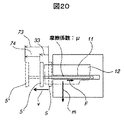
図20は、冷凍室5開放時における、開放速度と移動量との関係を示した図である。冷凍室5は扉開閉装置10によって、各駆動ピンから各押し面を介して開き方向に付勢され、移動量33の範囲まで開かれて、位置5′に達する。ここで、位置5′において冷凍室5は速度Vをもっている。その後、惰性開き量74の範囲では惰性によって開放方向へ移動を続け、徐々に減速して最終的に最大開き量73の位置5″まで移動して停止する。   FIG. 20 is a diagram showing the relationship between the opening speed and the movement amount when the freezer compartment 5 is opened. The freezer compartment 5 is urged by the door opening / closing device 10 in the opening direction from each drive pin through each push surface, is opened to the range of the movement amount 33, and reaches the position 5 ′. Here, the freezer compartment 5 has a velocity V at the position 5 ′. Thereafter, in the range of the inertia opening amount 74, the movement continues in the opening direction due to inertia, gradually decelerates and finally moves to the position 5 ″ of the maximum opening amount 73 and stops.

ここで、収容された食品を含めた冷凍室5の全体の質量をmとすれば、移動量33の位置における運動エネルギEは、
E=(m×V^2)/2 (式1)
となる。
Here, if the total mass of the freezer compartment 5 including the contained food is m, the kinetic energy E at the position of the movement amount 33 is
E = (m × V ^ 2) / 2 (Formula 1)
It becomes.

ここで、スライドレール11のもつ摩擦係数をμ、重力加速度をgとすれば、スライドレール11により生じる摩擦力Fは、
F=μ×m×g (式2)
となる。摩擦力により消費されるエネルギE2は、摩擦力Fと惰性開き量74(摩擦を受けながら移動した距離L)との積なので、
E2=L×F=L×μ×m×g (式3)
となる。ここで、元々冷凍室が持っていた運動エネルギが、停止するまでにすべて摩擦によって消費されたとすればE=E2なので、
(m×V^2)/2=L×μ×m×g (式4)
となる。両辺をmで割って、
(V^2)/2=L×μ×g (式5)
となる。ゆえに、惰性開き量74(すなわちL)は(式5)を変形して、
L=(V^2)/(2×μ×g) (式6)
として表される。
Here, if the friction coefficient of the slide rail 11 is μ and the gravitational acceleration is g, the frictional force F generated by the slide rail 11 is
F = μ × m × g (Formula 2)
It becomes. The energy E2 consumed by the frictional force is the product of the frictional force F and the inertia opening amount 74 (distance L moved while receiving friction).
E2 = L × F = L × μ × m × g (Formula 3)
It becomes. Here, if all of the kinetic energy that the freezer originally had was consumed by friction before stopping, E = E2,
(M × V ^ 2) / 2 = L × μ × m × g (Formula 4)
It becomes. Divide both sides by m,
(V ^ 2) / 2 = L × μ × g (Formula 5)
It becomes. Therefore, the inertia opening amount 74 (that is, L) deforms (Equation 5),
L = (V ^ 2) / (2 × μ × g) (Formula 6)
Represented as:

式6により、惰性開き量74(すなわちL)は、スライドレールの摩擦係数μと速度Vによって導かれる。ここで速度Vは、駆動ピンと押し面とが離反して、惰性で開き始める時点での速度である。また、摩擦抵抗μはスライドレール11によって定まる一定値である。   According to Equation 6, the inertia opening amount 74 (that is, L) is derived from the friction coefficient μ and the speed V of the slide rail. Here, the speed V is a speed at the time when the drive pin and the pressing surface are separated from each other and start to open by inertia. The frictional resistance μ is a constant value determined by the slide rail 11.

よって、速度Vを略一定にすれば、最大開き量73を略一定にすることができる。そこで、駆動機構15の減速比を大きくして、モータ24にかかる負荷トルク変動を小さくする。例えば減速比を1/100以上にすることが望ましい。これにより、モータ24による出力トルクに余裕が増えて、冷凍室収納食品の量に関わらず、モータ24の回転速度を略一定になるため、最大開き量73を略一定にできる。   Therefore, if the speed V is made substantially constant, the maximum opening amount 73 can be made substantially constant. Therefore, the reduction ratio of the drive mechanism 15 is increased to reduce the load torque fluctuation applied to the motor 24. For example, it is desirable that the reduction ratio is 1/100 or more. As a result, a margin is increased in the output torque by the motor 24, and the rotational speed of the motor 24 becomes substantially constant regardless of the amount of food stored in the freezer, so that the maximum opening amount 73 can be made substantially constant.

また、位置5′における速度Vは、第三の駆動ピン20cがもつ開き方向23dの速度である。よって速度Vは、回転板19の回転速度に比例する。さらに、接点75d(第三の駆動ピン20cと第三の押し面21cとの接点)と駆動軸18間の距離、すなわち回転半径rに比例する。ここで、図6(c)から図6(d)において、駆動軸18と接点75cとを通る直線と、開き方向23cを示す直線とが、ほぼ直交する位置に接点75cがある。そのため、連結板16が開き方向23へ移動する速度は、第三の駆動ピン20cが駆動軸18のまわりに回転する際の周速に略等しくなる。   The speed V at the position 5 ′ is the speed in the opening direction 23d of the third drive pin 20c. Therefore, the speed V is proportional to the rotational speed of the rotating plate 19. Furthermore, it is proportional to the distance between the contact point 75d (the contact point between the third drive pin 20c and the third push surface 21c) and the drive shaft 18, that is, the rotation radius r. Here, in FIG. 6C to FIG. 6D, the contact point 75c is located at a position where a straight line passing through the drive shaft 18 and the contact point 75c and a straight line indicating the opening direction 23c are substantially orthogonal to each other. Therefore, the speed at which the connecting plate 16 moves in the opening direction 23 is substantially equal to the peripheral speed when the third drive pin 20 c rotates around the drive shaft 18.

(扉自動閉鎖動作)冷蔵庫では、マグネットパッキン14と冷蔵庫本体1との間に隙間ができ、所謂半ドア状態になることがある。このような半ドア状態における扉開閉装置
10の動作について、図7を用いて説明する。
(Automatic door closing operation) In the refrigerator, a gap is formed between the magnet packing 14 and the refrigerator main body 1, and a so-called half-door state may occur. The operation of the door opening and closing device 10 in such a half door state will be described with reference to FIG.

図7は本発明による扉開閉装置10が冷凍室5を閉鎖する際の動作を示す図である。
(a)は冷凍室5が開いており、連結板16の左端が引込位置34よりも、開き量35移動した状態を示している。これは、扉開閉装置10によって閉じ駆動動作が可能な範囲である。通常、冷凍室5にはクローザ13が設けられているので、クローザ13の引き込み力によって冷凍室は閉じられるが、食品の一部が引っかかったり、スライドレール11の動作が一時的に渋くなったりして引き込まれない場合がある。
FIG. 7 is a view showing an operation when the door opening and closing device 10 according to the present invention closes the freezer compartment 5.
(A) shows a state where the freezer compartment 5 is open, and the left end of the connecting plate 16 is moved by an opening amount 35 from the retracting position 34. This is a range in which the door opening / closing device 10 can be closed and driven. Usually, since the freezer 5 is provided with the closer 13, the freezer is closed by the pulling force of the closer 13, but a part of the food is caught or the operation of the slide rail 11 becomes temporarily awkward. May not be pulled in.

ここで、連結板16には、受け面21aとは反対面であって、かつ扉側の面に、戻し面22が形成されている。これにより、回転板19を駆動軸18の周りに矢印CW方向(時計回り)に回転させると、第三の駆動ピン20cは戻し面22に当接する。図7(b)は、図7(a)からさらに回転板19を矢印CW方向に回転させた状態である。連結板16は第三の駆動ピン20cによって、矢印36方向(扉閉鎖方向)に付勢されて、連結板
16の図示左端が引込位置34に至るまで移動する。なお、図7(b)に示した位置は、マグネットパッキン14が冷蔵庫本体1に吸着して完全に閉じられた位置である。
Here, the connecting plate 16 is provided with a return surface 22 on the surface on the door side opposite to the receiving surface 21a. As a result, when the rotating plate 19 is rotated around the drive shaft 18 in the arrow CW direction (clockwise), the third drive pin 20 c comes into contact with the return surface 22. FIG. 7B shows a state in which the rotating plate 19 is further rotated in the arrow CW direction from FIG. The connecting plate 16 is urged in the direction of the arrow 36 (door closing direction) by the third drive pin 20 c, and the illustrated left end of the connecting plate 16 moves to the retracted position 34. Note that the position shown in FIG. 7B is a position where the magnet packing 14 is attracted to the refrigerator body 1 and completely closed.

その後、回転板19を矢印CCW方向(反時計回り)に回転して図7(c)の状態で停止する。これは、図3に示したと同様な位置である。   Thereafter, the rotating plate 19 is rotated in the direction of the arrow CCW (counterclockwise) and stopped in the state of FIG. This is the same position as shown in FIG.

上記のように、回転板19を扉開方向と反対方向に回転させることにより、冷凍室5が所謂半ドア状態になったとしても、連結板16は冷凍室5が閉じる方向に付勢されて、半ドアを防止できる。   As described above, by rotating the rotating plate 19 in the direction opposite to the door opening direction, the connecting plate 16 is biased in the direction in which the freezing chamber 5 is closed even if the freezing chamber 5 is in a so-called half-door state. Can prevent half doors.

冷凍室扉5aを閉じる際、マグネットパッキン14を引き剥がす力は要さず、かつクローザ13による引き込み力が生じる。そのため、扉開閉装置10によって加える閉じ力は、開き力と比べて弱い力でよい。本実施例によれば、冷凍室5を閉じる際には、駆動軸
18から最も遠方にある第三の駆動ピン20cが、連結板16の戻し面22を押すように構成されている。よって、駆動軸18に加わる駆動トルクが、開き時と同一であっても、閉じ力は開き力と比べてr1/r3だけ小さくなるので好適である。さらに、冷凍室5と冷蔵庫本体1との間に指などを挟み込んでしまった場合、挟む力は小さく安全性を高めることができる。
When closing the freezer compartment door 5a, a force for peeling the magnet packing 14 is not required, and a pulling force by the closer 13 is generated. Therefore, the closing force applied by the door opening / closing device 10 may be weaker than the opening force. According to the present embodiment, when the freezer compartment 5 is closed, the third drive pin 20 c farthest from the drive shaft 18 is configured to push the return surface 22 of the connecting plate 16. Therefore, even if the drive torque applied to the drive shaft 18 is the same as that at the time of opening, the closing force is preferably reduced by r1 / r3 compared to the opening force. Furthermore, when a finger or the like is sandwiched between the freezer compartment 5 and the refrigerator main body 1, the clamping force is small and safety can be improved.

また、冷凍室5において開動作よりも閉動作が低速なので、安全性を更に高めることができる。   Further, since the closing operation is slower than the opening operation in the freezer compartment 5, safety can be further improved.

ここで、閉じ駆動可能な範囲である開き量35について、図2により説明する。開き量35は、冷凍室5の前面を形成する扉厚さ71よりも小とすることが望ましい。開き量
35が扉厚さ71よりも大だと、冷凍室5を引き込み開始する際、冷凍室扉5aと野菜室6(または切り替え室3)の扉との間に隙間72が生じ、指などを挟みこむ恐れがある。そこで、開き量35が扉厚さ71よりも小となる本構成では、指などを挟まれる恐れがなく、安全性を向上できる。
Here, the opening amount 35 which is a range in which the closing drive is possible will be described with reference to FIG. The opening amount 35 is desirably smaller than the door thickness 71 that forms the front surface of the freezer compartment 5. If the opening amount 35 is larger than the door thickness 71, when the freezer compartment 5 is started to be retracted, a gap 72 is generated between the freezer compartment door 5a and the vegetable compartment 6 (or the switching chamber 3), such as a finger. There is a risk of pinching. Therefore, in the present configuration in which the opening amount 35 is smaller than the door thickness 71, there is no possibility that a finger or the like is caught, and safety can be improved.

(扉手動開閉動作)次に図8を用いて、冷凍室5が閉状態における回転板19の位置について説明する。扉開閉装置10を備えた冷蔵庫であっても、冷凍室5をユーザが手で引出したい場合が想定される。また、故障により扉開閉装置10が動作しない場合は、ユーザが手動で開閉できる構成がよい。この場合、扉開閉装置10が原因でユーザの手動動作を妨げたり、重くなったりしないことが望ましい。   (Manual Door Opening / Closing Operation) Next, the position of the rotating plate 19 when the freezer compartment 5 is closed will be described with reference to FIG. Even if it is a refrigerator provided with the door opening and closing apparatus 10, the case where a user wants to pull out the freezer compartment 5 by hand is assumed. Moreover, when the door opening / closing apparatus 10 does not operate | move by failure, the structure which a user can open and close manually is good. In this case, it is desirable that the manual operation of the user is not hindered or heavy due to the door opening and closing device 10.

図8において、連結板16は図示左端が引き込み位置34に合致しており、冷凍室扉
5aが閉鎖された位置である。ユーザが手動で冷凍室扉5aを閉鎖状態から引出して開くと、容器12の下方に設けられている連結板16は、冷凍室扉5aの開放方向(図8においては左方)に移動して、連結板16′の位置に至る。ここで、連結板16に設けられた第二の受け面21bの先端(第二の先端37b)と、第一の駆動ピン20aとの間に隙間38が形成される。これにより、手動で冷凍室5を引出す際に連結板と駆動ピンとは接触しない。つまり、連結板16が開放方向に移動する際、回転板19に接触しないので抵抗にならず、冷凍室5を引出し自在に開くことができる。
In FIG. 8, the left end of the connecting plate 16 coincides with the retracted position 34, and the freezer compartment door 5a is closed. When the user manually pulls and opens the freezer compartment door 5a from the closed state, the connecting plate 16 provided below the container 12 moves in the opening direction of the freezer compartment door 5a (leftward in FIG. 8). To the position of the connecting plate 16 '. Here, a gap 38 is formed between the tip of the second receiving surface 21b (second tip 37b) provided on the connecting plate 16 and the first drive pin 20a. Thereby, when pulling out the freezer compartment 5 manually, a connection plate and a drive pin do not contact. That is, when the connecting plate 16 moves in the opening direction, it does not come into contact with the rotating plate 19, so there is no resistance, and the freezer compartment 5 can be opened freely.

次に回転板19′は、連結板16に設けられた第一のピン20aの先端(第一の先端
37a)と、第三の駆動ピン20cとの間に隙間39がある。これにより、手動で冷凍室5を引出す際、連結板16と駆動ピンとが接触しないので、自在に冷凍室5を引出して開くことができる。
Next, in the rotating plate 19 ′, there is a gap 39 between the tip (first tip 37a) of the first pin 20a provided on the connecting plate 16 and the third drive pin 20c. Thereby, when pulling out the freezer compartment 5 manually, since the connection plate 16 and the drive pin do not contact, the freezer compartment 5 can be pulled out freely and opened.

上記のように、ユーザが手動で冷凍室5を開閉する際、連結板16と駆動ピン20とが接触しないようにする。つまり、駆動軸18と第一の駆動ピン20aとを結ぶ直線が、原点範囲40の角度範囲内にあればよい。したがって、冷凍室5を閉鎖した場合には、回転板19が上記の原点範囲40になるように設定すれば、手動で開閉する際にも使い勝手を向上できる。   As described above, when the user manually opens and closes the freezer compartment 5, the connecting plate 16 and the drive pin 20 are prevented from contacting each other. That is, the straight line connecting the drive shaft 18 and the first drive pin 20 a may be within the angle range of the origin range 40. Therefore, when the freezer compartment 5 is closed, if the rotating plate 19 is set to be within the above-described origin range 40, the usability can be improved even when manually opening and closing.

このような回転板19の角度範囲を本発明では、原点範囲にある、と称する。   In the present invention, such an angle range of the rotating plate 19 is referred to as being in the origin range.

(制御系の構成)次に図9を用いて、扉開閉装置10の駆動制御系について説明する。図9は、制御系の構成を示すブロック図である。   (Configuration of Control System) Next, the drive control system of the door opening / closing device 10 will be described with reference to FIG. FIG. 9 is a block diagram showing the configuration of the control system.

開スイッチ8を備えた操作表示部7は、ユーザが開スイッチ8を押した際にその信号を制御回路41に送る。冷凍室5および野菜室6に設けられた夫々の駆動機構15のモータ24と、駆動軸18の回転位置を検出する回転検知手段32、および扉の開閉状態を検出するドア検知17とは、制御回路41に接続されている。   The operation display unit 7 including the open switch 8 sends a signal to the control circuit 41 when the user presses the open switch 8. The motor 24 of each drive mechanism 15 provided in the freezer compartment 5 and the vegetable compartment 6, the rotation detection means 32 for detecting the rotational position of the drive shaft 18, and the door detection 17 for detecting the open / closed state of the door are controlled. The circuit 41 is connected.

扉開閉装置10および制御回路41の駆動に必要な電力は、電源42から供給される。   Electric power necessary for driving the door opening / closing device 10 and the control circuit 41 is supplied from a power source 42.

回転検知手段32は、軸の回転によって抵抗値が変化する可変抵抗器や、軸の所定の回転位置を検出するマイクロスイッチ等であってもよい。   The rotation detection means 32 may be a variable resistor whose resistance value changes with rotation of the shaft, a microswitch that detects a predetermined rotation position of the shaft, or the like.

ドア検知17は、冷凍室扉5aが完全に閉じられているか否かを検出する第一のドア検知17aと、冷凍室扉5aの開き量が所定の開き量35以下であるか否かを検出する第二のドア検知17bとで構成される。例えば、扉に備えられたマグネットと冷蔵庫本体1に備えられたホール素子や、マイクロスイッチなどの検知手段であってもよい。   The door detection 17 detects the first door detection 17a for detecting whether or not the freezer compartment door 5a is completely closed, and detects whether or not the opening amount of the freezer compartment door 5a is a predetermined opening amount 35 or less. Second door detection 17b. For example, it may be a detection means such as a magnet provided on the door and a hall element provided on the refrigerator main body 1 or a micro switch.

操作表示部7には、扉が半ドア状態になっていることをユーザに知らせるための報知手段70が備えられていてもよい。この報知手段70の一例は、ブザーを鳴動させたり、ランプを点灯又は点滅させたりするものがよい。   The operation display unit 7 may be provided with notification means 70 for notifying the user that the door is in a half-door state. An example of the notification means 70 is preferably one that sounds a buzzer or lights or blinks a lamp.

(扉開放制御)次に図10を用いて、冷凍室5を開放する際の開き制御の手順について説明する。図10は冷凍室5を開放する際の制御を示す流れ図である。   (Door Open Control) Next, with reference to FIG. 10, the procedure for opening control when the freezer compartment 5 is opened will be described. FIG. 10 is a flowchart showing the control when the freezer compartment 5 is opened.

開き動作を開始(ブロック43)すると、制御回路41は回転検知手段32の状態を監視して、駆動機構15の回転板19が動作を開始する原点範囲40にあるか否かを検出する(ブロック44)。ここで、原点範囲40とは、図8にて説明したように、冷凍室5を手動で開閉動作した場合にも、連結板16が駆動ピン20と干渉することがない範囲にある状態のことをいう。   When the opening operation is started (block 43), the control circuit 41 monitors the state of the rotation detecting means 32 and detects whether or not the rotating plate 19 of the drive mechanism 15 is in the origin range 40 where the operation starts (block). 44). Here, the origin range 40 is a state in which the connecting plate 16 does not interfere with the drive pin 20 even when the freezer compartment 5 is manually opened and closed as described with reference to FIG. Say.

もし、回転板16が原点範囲40にない場合には、モータ24に通電(ブロック45)して、回転板16を回転させて原点範囲40になるようにする。モータ24をCW方向に回転させるか、あるいはCCW方向に回転させるかは、回転検知手段32からの信号によって判定する。具体的には、回転板16が原点範囲40に対してどちらの方向にずれているかを制御回路41が判定して、モータ24に対して駆動電圧の印加方向を定める。   If the rotating plate 16 is not in the origin range 40, the motor 24 is energized (block 45) to rotate the rotating plate 16 so that the origin range 40 is reached. Whether the motor 24 is rotated in the CW direction or the CCW direction is determined by a signal from the rotation detecting means 32. Specifically, the control circuit 41 determines in which direction the rotating plate 16 is displaced with respect to the origin range 40 and determines the direction in which the drive voltage is applied to the motor 24.

回転板19が原点範囲40にあることが検出され、かつユーザによって開スイッチ8が操作されたことを制御回路41が検出したら、モータ24を通電(ブロック47)して、回転板19を回転させる。このときの回転板19の回転方向は、図3であればCCW方向としており、回転板19が回転すると、図6にて説明したように連結板16が駆動ピン
20に付勢されて冷凍室5が開く。モータ24が引き続き回転して、回転検知手段32により検出された回転板19の回転位置が原点範囲40に入ったことが確認できたら(ブロック48)、モータを停止させて(ブロック49)一連の開き動作を終了する(ブロック50)。
When it is detected that the rotating plate 19 is in the origin range 40 and the control circuit 41 detects that the open switch 8 is operated by the user, the motor 24 is energized (block 47) to rotate the rotating plate 19. . The rotating direction of the rotating plate 19 at this time is the CCW direction in FIG. 3, and when the rotating plate 19 rotates, the connecting plate 16 is urged by the drive pin 20 as described in FIG. 5 opens. When it is confirmed that the motor 24 continues to rotate and the rotational position of the rotating plate 19 detected by the rotation detecting means 32 has entered the origin range 40 (block 48), the motor is stopped (block 49). The opening operation is terminated (block 50).

次に、モータに通電(ブロック47)させて冷凍室5を開き始める際の電圧の加え方について説明する。モータを通電する際に定格電圧を急峻に加えると、モータのコイルには突入電流が流れるので、モータは最大の出力トルクを出して停止状態から急激に回転し始める。したがって、冷凍室5が開き始める際には最大の加速を行うことになり、開き始めの動作が急峻で勢いよく開いてしまう。   Next, how to apply a voltage when energizing the motor (block 47) and starting to open the freezer compartment 5 will be described. If the rated voltage is applied steeply when the motor is energized, an inrush current flows through the motor coil, so that the motor outputs maximum output torque and starts to rotate rapidly from a stopped state. Therefore, when the freezer compartment 5 starts to open, maximum acceleration is performed, and the opening operation starts sharply and vigorously.

そこで、モータ24に通電(ブロック47)する際に定格電圧を急峻に加えるのではなく、通電の当初は一例として定格電圧の1/2程度の低電圧を加え、扉開閉装置10の駆動開始後、冷凍室5が開くに伴って、徐々に電圧を高くする。図6(c)から(d)において、駆動ピン20から連結板16へ伝達される開き方向23の速度が最大になるまでの範囲で、連続的に、あるいは断続的に電圧を上昇させて定格電圧に至るような電圧変化の通電を行うことが望ましい。そのように電圧を徐々に増加させることにより、冷凍室5が開きはじめる際の動作がゆっくりとなるので、勢い良く開くことがなく、開き方に高級感を付与できる。   Therefore, when the motor 24 is energized (block 47), the rated voltage is not suddenly applied, but at the beginning of energization, a low voltage of about 1/2 of the rated voltage is applied as an example, and after the door opening / closing device 10 starts driving. As the freezer compartment 5 opens, the voltage is gradually increased. 6 (c) to 6 (d), the voltage is continuously increased or intermittently increased until the speed in the opening direction 23 transmitted from the drive pin 20 to the connecting plate 16 is maximized. It is desirable to energize the voltage change to reach the voltage. By gradually increasing the voltage in such a manner, the operation when the freezer compartment 5 starts to open becomes slow, so that it is not opened vigorously, and a high-class feeling can be given to the way of opening.

またさらに、図6(e)の状態を過ぎた後、回転板19は矢印CCW方向に回転を継続して後、図6(a)に示した位置まで回転してから停止する。冷凍室5が開いた後は回転板19には負荷がかからずに空転する状態となる。したがって、図6(e)の状態を過ぎた後は、モータ24に加える電圧を定格電圧よりも低くして、モータ24の回転速度を低速としてもよい。そのようにモータ24の回転を低速とすることで、モータ24から生じる騒音や振動を低減して静粛な動作を実現できる。さらに、回転板19を低速で回転させることによって、モータ24が停止時に行き過ぎることがなく、図8にて説明した原点範囲40に確実に停止でき、精度を向上できる。   Furthermore, after passing the state of FIG. 6E, the rotating plate 19 continues to rotate in the direction of the arrow CCW, and then rotates to the position shown in FIG. 6A and then stops. After the freezer compartment 5 is opened, the rotating plate 19 is idled without being loaded. Therefore, after passing the state of FIG. 6 (e), the voltage applied to the motor 24 may be made lower than the rated voltage, and the rotational speed of the motor 24 may be made low. By reducing the rotation of the motor 24 as described above, noise and vibration generated from the motor 24 can be reduced and a quiet operation can be realized. Furthermore, by rotating the rotating plate 19 at a low speed, the motor 24 does not go too far when stopped, and can be reliably stopped within the origin range 40 described with reference to FIG. 8, and the accuracy can be improved.

(扉開閉スイッチ構成)次に、本発明による扉開閉機構に使用者が開き指示を与える際のスイッチ構成について説明する。図21は、本発明による扉開閉機構を備えた冷蔵庫の部分断面図であり、図22は図21に示したS部の拡大図を示している。S部は冷凍室5の前面を構成する扉体5aの上縁と、扉が閉じられた際に扉と当接する本体1側の枠体
87の近傍を示している。
(Door Open / Close Switch Configuration) Next, the switch configuration when the user gives an opening instruction to the door open / close mechanism according to the present invention will be described. FIG. 21 is a partial cross-sectional view of a refrigerator provided with a door opening / closing mechanism according to the present invention, and FIG. 22 is an enlarged view of an S portion shown in FIG. S part has shown the vicinity of the upper edge of the door body 5a which comprises the front surface of the freezer compartment 5, and the frame body 87 by the side of the main body 1 which contact | abuts a door when a door is closed.

扉体5aの前方上部には、押しボタン88が設けられており、扉体5a前面よりも突出している。押しボタン88の奥側には、押し棒89が設けられており、押しボタン88と押し棒89とは扉体5aを貫通してスライド可能に支持されている。押しボタン88と押し棒89とは戻しスプリング90によって生じる戻し力によって、図22(a)において図示左向きに付勢されて、図示しないストッパなどによって位置が保持される。   A push button 88 is provided in the upper front part of the door body 5a and protrudes from the front surface of the door body 5a. A push rod 89 is provided on the back side of the push button 88, and the push button 88 and the push rod 89 are slidably supported through the door body 5a. The push button 88 and the push bar 89 are urged leftward in the drawing in FIG. 22A by the return force generated by the return spring 90, and their positions are held by a stopper or the like (not shown).

枠体87の扉体5aと接する側には、マイクロスイッチなどのスイッチ本体92が設けられており、枠体87の内部をスイッチ94から制御回路41に至る配線94が設けられている。   A switch body 92 such as a micro switch is provided on the side of the frame body 87 that contacts the door body 5 a, and a wiring 94 that extends from the switch 94 to the control circuit 41 is provided inside the frame body 87.

使用者が押しボタン88を手で押すと、図22(b)に示すように押しボタン88と押し棒89とが押し量91だけ図示右方に移動できるように構成されている。押し棒89がスイッチ本体92に設けられたプランジャ93を押して、スイッチ本体92内部に設けられた図示しない接点を閉じて、使用者が押しボタン88を押した信号を制御回路41に伝達することができる。   When the user presses the push button 88 with his / her hand, the push button 88 and the push bar 89 are configured to move to the right in the figure by a push amount 91 as shown in FIG. The push rod 89 pushes the plunger 93 provided in the switch main body 92 to close a contact (not shown) provided in the switch main body 92 and transmit a signal that the user has pressed the push button 88 to the control circuit 41. it can.

使用者が押しボタン88から手を離すと、戻しスプリング90から発生する力によって、押しボタン88と押し棒89とは図示左側に移動する。そして、プランジャ93が復帰してスイッチ本体92内部の接点が開放された、図22(a)の状態に戻る。   When the user releases his / her hand from the push button 88, the push button 88 and the push bar 89 are moved to the left in the figure by the force generated from the return spring 90. Then, the plunger 93 is returned to the state shown in FIG. 22A in which the contact inside the switch body 92 is opened.

これにより、スイッチ本体92と、制御回路41とを接続する配線は本体側の枠体87の内部に設けられる構成とできるので、扉体5aには配線を設ける必要がない、という効果がある。   Thereby, since the wiring which connects the switch main body 92 and the control circuit 41 can be provided inside the frame body 87 on the main body side, there is an effect that it is not necessary to provide the wiring in the door body 5a.

また、冷凍室5を引き出す際に配線94は一緒に引き出されないので、開閉の際に配線94が絡まったり何かに引っかかったりすることがない。   Further, since the wiring 94 is not pulled out together when the freezer compartment 5 is pulled out, the wiring 94 is not tangled or caught by anything when opening and closing.

またさらに、使用者からみると押しボタン88を押した際には冷凍室5を奥側に閉じる方向の力を加えることになる。使用者が押しボタン88を押した途端に制御回路41からモータ24に通電されて冷凍室5が電動で矢印23方向に開く動作であるとすれば、冷凍室5は使用者が力を加えているのと反対方向、すなわち使用者の手前方向に開き始めるので、使用者にとって不自然な動作に感じる。   Further, when viewed from the user, when the push button 88 is pushed, a force in a direction to close the freezer compartment 5 to the back side is applied. As soon as the user pushes the push button 88, the motor 24 is energized from the control circuit 41 and the freezer compartment 5 is electrically operated to open in the direction of the arrow 23. Since it starts to open in the opposite direction, that is, toward the user, it feels unnatural for the user.

そこで、使用者が押しボタン88を押した時点ではモータ24に通電されず、一旦押した押しボタン88から手を離した際にモータ24に通電される制御とする、これにより、使用者が押しボタン88を押して、押しボタン88から手を離す(手を押しボタン88前方に引く)動作に付随するように冷凍室5が手前に開いてくるので、使用者の手の動く方向と冷凍室5の動く(開く)方向とが同一となる。よって、使用者から見て動作に対する違和感がなく、自然な操作感が得られる、という効果がある。   Therefore, when the user presses the push button 88, the motor 24 is not energized, and when the user releases the push button 88, the motor 24 is energized. The freezer compartment 5 opens forward to accompany the operation of pressing the button 88 and releasing the hand from the pushbutton 88 (pulling the hand forward of the pushbutton 88). The direction of movement (opening) is the same. Therefore, there is an effect that there is no sense of incongruity in the operation as seen from the user, and a natural feeling of operation can be obtained.

この動作は、使用者が押しボタン88から手を離すとスイッチ本体92内部の接点が開放された状態に戻る。制御回路41がそれを検出してモータ24に通電されて冷凍室5が電動で開く動作とする。   In this operation, when the user releases the push button 88, the contact in the switch body 92 is returned to the open state. The control circuit 41 detects this and energizes the motor 24 to open the freezer compartment 5 electrically.

(扉自動閉鎖制御)次に、図11を用いて、冷凍室5が完全に閉じていない、所謂半ドア状態から冷凍室5を閉じる際の制御の手順について説明する。図11は冷凍室5を閉じる際の閉じ制御の手順を示す流れ図である。動作を開始(ブロック51)してから原点範囲を検出(ブロック52)するまでモータ24に通電する(ブロック53)制御については、図10のブロック43からブロック45と同一である。   (Automatic door closing control) Next, a control procedure for closing the freezer compartment 5 from a so-called half-door state in which the freezer compartment 5 is not completely closed will be described with reference to FIG. FIG. 11 is a flowchart showing the procedure of closing control when closing the freezer compartment 5. Control for energizing the motor 24 (block 53) from the start of operation (block 51) until the origin range is detected (block 52) is the same as block 43 to block 45 in FIG.

第一のドア検知17aが冷凍室扉5aを検出していれば、冷凍室扉5aは半ドア状態ではなくて閉鎖されていることが確認できるので、ドア閉じ動作を完了する(ブロック55)。第一のドア検知17aがドアの閉鎖を検出できず、かつドアと冷蔵庫本体1との開き量が開き量35以下であることを第二のドア検知17bが検出した場合、冷凍室5は開き量35以下で開いた状態にある。もし、第二のドア検知17bが扉を検出しない場合、冷凍室5は開き量35以上に開いているので、本発明の扉開閉装置10では閉じることができない範囲である。その場合は、報知手段70を鳴動させて半ドアであることをアラームでユーザに報知する(ブロック57)。   If the first door detection 17a detects the freezer compartment door 5a, it can be confirmed that the freezer compartment door 5a is not in a half-door state but is closed, and thus the door closing operation is completed (block 55). When the first door detection 17a cannot detect the closing of the door and the second door detection 17b detects that the opening amount between the door and the refrigerator body 1 is 35 or less, the freezer compartment 5 is opened. It is in an open state with an amount of 35 or less. If the second door detection 17b does not detect the door, the freezer compartment 5 is opened to an opening amount of 35 or more, so that it cannot be closed by the door opening and closing device 10 of the present invention. In that case, the notification means 70 is ringed to notify the user that it is a half-door (block 57).

もし、第二のドア検知17bが扉を検知できれば、冷凍室5は半ドア状態であってかつ扉開閉装置10によって閉鎖可能な範囲なので、モータ24に通電する(ブロック58)。このときの回転方向は、図7においてはCW方向である。さらに、これにより、モータ24に印加する電圧を、例えば定格電圧の1/2ないし1/3程度と低くする。回転板
16が低速度でCW方向に回転するので、第三の駆動ピン20cが連結板19の第三の受け面21cに衝突する衝撃を緩和できる。
If the second door detection 17b can detect the door, the freezer compartment 5 is in a half-door state and can be closed by the door opening / closing device 10, and therefore the motor 24 is energized (block 58). The rotation direction at this time is the CW direction in FIG. Further, this reduces the voltage applied to the motor 24 to about 1/2 to 1/3 of the rated voltage, for example. Since the rotating plate 16 rotates in the CW direction at a low speed, the impact of the third drive pin 20c colliding with the third receiving surface 21c of the connecting plate 19 can be reduced.

モータ24をCW方向に所定時間、例えば3秒間通電すれば(ブロック59)、回転板19は図7(b)の状態に至って連結板16を矢印36方向に、すなわち冷凍室5を閉じる方向に移動させて冷凍室5を閉じる。所定時間経過した後に、モータ24がCCW方向に回転するよう通電して(ブロック60)、回転板19が原点範囲40(図8に示す)になるまで回転させる。回転検知手段32の信号によって原点範囲40にあることが検出すると(ブロック61)、モータ24の回転を停止させる(ブロック62)。ここで、第一のドア検知17aによって冷凍室5が閉鎖されていることを検出して(ブロック63)、冷凍室5は完全に閉鎖されたことを確認して、処理を終了する(ブロック66)。もし、第一のドア検知17aが冷凍室5の閉鎖を検知できなければ、半ドア状態が継続していると判断できるので、ブロック58からブロック63までの処理、すなわちモータ24に通電して回転板19をCW方向に回転して冷凍室5を閉鎖させる動作を複数回繰り返して行う(ブロック64)。もし、所定の回数、例えば3回この閉鎖動作を繰り返した後も第一のドア検知17aの閉鎖を検知できなければ、例えば何かが挟まっていて冷凍室5を閉鎖できないと判定して、報知手段70を鳴動させて半ドアであるというアラームをユーザに報知する(ブロック65)。   If the motor 24 is energized in the CW direction for a predetermined time, for example, 3 seconds (block 59), the rotating plate 19 reaches the state shown in FIG. 7B and the connecting plate 16 is moved in the direction of arrow 36, that is, in the direction of closing the freezer compartment 5. The freezer 5 is closed by moving. After a predetermined time has elapsed, the motor 24 is energized so as to rotate in the CCW direction (block 60), and the rotating plate 19 is rotated until it reaches the origin range 40 (shown in FIG. 8). When it is detected by the signal from the rotation detecting means 32 that the position is within the origin range 40 (block 61), the rotation of the motor 24 is stopped (block 62). Here, the first door detection 17a detects that the freezer compartment 5 is closed (block 63), confirms that the freezer compartment 5 is completely closed, and ends the process (block 66). ). If the first door detection 17a cannot detect the closing of the freezer compartment 5, it can be determined that the half-door state is continuing, so the processing from block 58 to block 63, that is, the motor 24 is energized and rotated. The operation of rotating the plate 19 in the CW direction to close the freezer compartment 5 is repeated a plurality of times (block 64). If it is not possible to detect the closing of the first door detection 17a even after repeating this closing operation a predetermined number of times, for example, three times, it is determined that, for example, something is caught and the freezer compartment 5 cannot be closed. The means 70 is sounded to notify the user of an alarm that the door is half-door (block 65).

また、使用者がドア開スイッチ8を誤って押して冷凍室5が開いて、使用者の体に当たるなどの現象を防止するために、図10にて説明した冷凍室5の開き動作を行わないように開スイッチの動作を無効にして、図11に示した閉じ動作のみを行うことをユーザが選択、設定可能な構成としても良い。   Further, in order to prevent a phenomenon that the user accidentally presses the door opening switch 8 to open the freezer compartment 5 and hit the user's body, the opening operation of the freezer compartment 5 described with reference to FIG. 10 is not performed. Alternatively, the operation of the open switch may be disabled and the user may select and set to perform only the closing operation shown in FIG.

(駆動伝達部材)次に、本発明における他の実施例について、図12を用いて説明する。実施例1では、回転板19に駆動ピンが3本設けられている。一方、本実施例においては、回転板19に第四の駆動ピン20dが、駆動軸18から距離r4(>r3)なる位置に設けられている。連結板16には、第四の駆動ピン20dが当接するための第四の受け面21dが設けられている。   (Drive transmission member) Next, another embodiment of the present invention will be described with reference to FIG. In the first embodiment, the rotary plate 19 is provided with three drive pins. On the other hand, in the present embodiment, the fourth drive pin 20 d is provided on the rotary plate 19 at a position at a distance r4 (> r3) from the drive shaft 18. The coupling plate 16 is provided with a fourth receiving surface 21d on which the fourth drive pin 20d abuts.

冷凍室5を開く動作の際は、図6に示したと同様の動作を行い、加えて第四の駆動ピン20dが第四の受け面21dを扉開放方向である図示左方に押すため、連結板16が回転板19から受ける力の範囲が拡大する。また、r4>r3なので、駆動軸18の回転速度が一定であるとすれば、第四の駆動ピン20dが第四の受け面21dを図示左方に押し出す速度は第四の駆動ピン20dがない場合と比べてr4/r3だけ大きくなる。このように、力の範囲と速度の両方が拡大されるので、冷凍室5の開き量が拡大して、快適な操作感を得ることかできる。   In the operation of opening the freezer compartment 5, the same operation as shown in FIG. 6 is performed, and in addition, the fourth drive pin 20 d pushes the fourth receiving surface 21 d to the left in the figure, which is the door opening direction. The range of force that the plate 16 receives from the rotating plate 19 is expanded. Further, since r4> r3, if the rotational speed of the drive shaft 18 is constant, the fourth drive pin 20d pushes the fourth receiving surface 21d to the left in the figure, and the fourth drive pin 20d does not. It becomes larger by r4 / r3 than the case. Thus, since both the range and speed of force are expanded, the opening amount of the freezer compartment 5 can be expanded and a comfortable operation feeling can be obtained.

さらに、回転板19を矢印CW方向に回転すると、連結板16は図7の矢印36方向に移動して冷凍室5を閉鎖する。ここで、r4>r3なので、連結板16の開き量35をほぼr4/r3だけ大きくしても、冷凍室5を閉鎖することができる。これにより、半ドア状態から閉鎖できる開き量35を拡大できる。よって、半ドアが発生しても、確実に冷凍室扉5aを閉鎖でき、省エネを実現できると共に、収納された食品が外気の侵入によって劣化するのを防止できる。   Further, when the rotating plate 19 is rotated in the direction of arrow CW, the connecting plate 16 moves in the direction of arrow 36 in FIG. 7 to close the freezer compartment 5. Here, since r4> r3, the freezer compartment 5 can be closed even if the opening amount 35 of the connecting plate 16 is increased by approximately r4 / r3. Thereby, the opening amount 35 which can be closed from a half door state can be expanded. Therefore, even if a half door occurs, the freezer compartment door 5a can be reliably closed, energy saving can be realized, and the stored food can be prevented from being deteriorated by the intrusion of outside air.

(扉自動開閉機構)次に図13〜図16にて、図3に示す扉開閉装置10とは別の実施例について説明する。冷凍室底面には駆動機構15が設けられている。駆動機構15は、駆動軸18で回動自在に軸支された回転板19が設けられている。この回転板19には、4段構成でストロークを拡大する駆動伝達部材である駆動ピン(第一の駆動ピン20a、第二の駆動ピン20b、第三の駆動ピン20c、第四の駆動ピン20d)が設けられている。   (Automatic Door Opening / Closing Mechanism) Next, an embodiment different from the door opening / closing device 10 shown in FIG. 3 will be described with reference to FIGS. A drive mechanism 15 is provided on the bottom of the freezer compartment. The drive mechanism 15 is provided with a rotating plate 19 that is pivotally supported by a drive shaft 18. The rotary plate 19 includes a drive pin (first drive pin 20a, second drive pin 20b, third drive pin 20c, and fourth drive pin 20d) that is a drive transmission member that expands the stroke in a four-stage configuration. ) Is provided.

そして、それぞれの駆動ピンと駆動軸18との間の距離については、先に述べた通りである。つまり、それぞれの距離の大小関係は、図12に示すように、r4>r3>r2>r1である。   The distance between each drive pin and the drive shaft 18 is as described above. That is, the magnitude relationship between the distances is r4> r3> r2> r1, as shown in FIG.

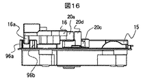
また、この駆動ピン20aと駆動ピン20dの高さ方向寸法Hは、図16に示すように駆動ピン20bと駆動ピン20cの高さ寸法hよりも、高く形成されている。一例として、駆動ピン20bと駆動ピン20cの高さ寸法はh=H/2となる。   Further, the height dimension H of the drive pin 20a and the drive pin 20d is formed higher than the height dimension h of the drive pin 20b and the drive pin 20c as shown in FIG. As an example, the height dimension of the drive pin 20b and the drive pin 20c is h = H / 2.

これにより、高さ方向寸法が異なるため、駆動ピン20bと駆動ピン20cは、駆動ピン20aと駆動ピン20dが当接する連結板16の受け面21bと受け面21cには当接しない構成となる。   Accordingly, since the height direction dimensions are different, the drive pin 20b and the drive pin 20c are configured not to come into contact with the receiving surface 21b and the receiving surface 21c of the connecting plate 16 with which the drive pin 20a and the drive pin 20d come into contact.

よって、回転板19と連結板16との間に異常が生じても、駆動ピン20bの受け面
21aへのかみ込みを防止し、回転板19と連結板16とがロックしてしまうことを防止できる。
Therefore, even if an abnormality occurs between the rotating plate 19 and the connecting plate 16, the driving pin 20b is prevented from being caught in the receiving surface 21a, and the rotating plate 19 and the connecting plate 16 are prevented from being locked. it can.

同様に、駆動ピン20cの受け面21dへのかみ込みも、高さ方向寸法の違いにより防止できる。   Similarly, the drive pin 20c can be prevented from biting into the receiving surface 21d due to the difference in height dimension.

回転板19には磁石95が設けられ、この磁石95は、回転板19の原点位置を特定するものである。   The rotating plate 19 is provided with a magnet 95, and this magnet 95 specifies the origin position of the rotating plate 19.

すなわち、回動後の回転板19は、先に述べたように常に図15に示す位置で止めるようにする。これにより、停電の場合でも連結板16に干渉されずに、扉を手動で開閉できる。   That is, the rotated rotating plate 19 is always stopped at the position shown in FIG. 15 as described above. Thereby, even in the case of a power failure, the door can be manually opened and closed without interference with the connecting plate 16.

具体的に回転検知手段は、図示しないホールICが回転板19の裏側の裏側のベース板15aに取り付けられており、このホールICにて磁石95が原点範囲40に位置していたか検知して、駆動軸18の停動を制御する。   Specifically, the rotation detecting means detects whether the Hall IC (not shown) is attached to the base plate 15a on the back side of the rotating plate 19, and the Hall 95 detects whether the magnet 95 is located in the origin range 40. The stop of the drive shaft 18 is controlled.

回転検出手段32は、軸の回転によって抵抗値が変化する可変抵抗器あるいは軸の所定位置を検出するマイクロスイッチなどの検出手段であってもよい。   The rotation detecting means 32 may be a detecting means such as a variable resistor whose resistance value changes with rotation of the shaft or a microswitch for detecting a predetermined position of the shaft.

駆動機構15を形成するベース板15aには、案内ガイド96が設けられている。この案内ガイド96は、連結板16を所定位置に案内するために、凸片96aと凸片96bとがベース板15aに併設して備えられている。凸片96aと凸片96bは、互いに所定の間隔で設けられており、入り口側の開口部においては、その間隔が広く形成されている。   A guide guide 96 is provided on the base plate 15 a forming the drive mechanism 15. The guide guide 96 is provided with a convex piece 96a and a convex piece 96b side by side with the base plate 15a in order to guide the connecting plate 16 to a predetermined position. The convex piece 96a and the convex piece 96b are provided at a predetermined interval from each other, and the interval is wide at the opening on the entrance side.

連結板16の摺動部16aが、案内ガイド96に入り易いようにしたためである。冷蔵庫本体側の寸法誤差や組立誤差、連結板16が組み付けられる引出し扉側の寸法誤差や組立誤差、等の影響により、案内ガイド96に沿って移動する摺動部16aの位置ずれが生じることがある。   This is because the sliding portion 16 a of the connecting plate 16 can easily enter the guide guide 96. Due to dimensional errors and assembly errors on the refrigerator main body side, dimensional errors and assembly errors on the drawer door side where the connecting plate 16 is assembled, misalignment of the sliding portion 16a that moves along the guide guide 96 may occur. is there.

そこで本構成は、駆動機構15の凸片96aと凸片96bとにより形成される開口部は、その間隔が他の所定間隔よりも広く形成されているので、案内ガイド96に摺動部16aが入り易い。   Therefore, in this configuration, since the opening formed by the convex piece 96a and the convex piece 96b of the drive mechanism 15 is formed wider than other predetermined intervals, the sliding portion 16a is formed on the guide guide 96. Easy to enter.

また、この凸片96bにはホールIC97とホールIC98とが設けられている。このホールIC97とホールIC98は、連結板16の摺動部16aに設けられた、磁石99の接近あるいは離反を検出して、回転軸18を駆動あるいは停止させる。   The convex piece 96b is provided with a Hall IC 97 and a Hall IC 98. The Hall IC 97 and the Hall IC 98 detect the approach or separation of the magnet 99 provided on the sliding portion 16a of the connecting plate 16, and drive or stop the rotating shaft 18.

さらに、ホールIC97は、冷凍室5の扉が完全に閉じられているか否かを検出する。ホールIC98は、冷凍室5の扉の開き量が所定の開き量(例えば閉じ駆動範囲である、開き量35以下)であるか否かを、連結板16側の磁石99を伴って検出する。   Furthermore, the Hall IC 97 detects whether or not the door of the freezer compartment 5 is completely closed. The Hall IC 98 detects whether the opening amount of the door of the freezer compartment 5 is a predetermined opening amount (for example, the closing drive range, which is 35 or less opening amount) with the magnet 99 on the connection plate 16 side.

すなわち、図16に示すように、ホールIC97とホールIC98に、磁石99が対向している時が、完全扉閉状態(例えば開き量35以下)である。磁石99がホールIC97
とホールIC98との間に位置している時が、半ドア状態ということになる。
That is, as shown in FIG. 16, when the magnet 99 faces the Hall IC 97 and the Hall IC 98, the door is completely closed (for example, the opening amount is 35 or less). Magnet 99 is Hall IC97
And the Hall IC 98 are in a half-door state.

回転板19と連結板16は実施例2において説明したのと同様に動作する。すなわち、半ドア状態のときに、図12に示すように回転板19をCW方向に回転させて引出し扉を閉じる制御をする。   The rotating plate 19 and the connecting plate 16 operate in the same manner as described in the second embodiment. That is, in the half door state, as shown in FIG. 12, the rotating plate 19 is rotated in the CW direction so as to close the drawer door.

そして、実施例2と本実施例において相違する点は以下の2点である。   The differences between the second embodiment and the present embodiment are the following two points.

1点目は、第一の受け面21aには第一の駆動ピン20aしか当接できない構造とした点である。すなわち、第一の駆動ピン20aと第二の駆動ピン20bとは、高さ寸法が異なるため、第二の駆動ピン20bは第一の受け面21aには当接しない。   The first point is that only the first drive pin 20a can be brought into contact with the first receiving surface 21a. That is, since the first drive pin 20a and the second drive pin 20b have different height dimensions, the second drive pin 20b does not contact the first receiving surface 21a.

2点目は、案内ガイド96を設け、この案内ガイド96を形成する凸片96bにホールIC97とホールIC98が設けられた点である。   The second point is that a guide guide 96 is provided, and a hall IC 97 and a hall IC 98 are provided on the convex piece 96b forming the guide guide 96.

すなわち、この2個のホールIC97とホールIC98と、連結板16側に設けた磁石99との位置関係に基づき、冷凍室5の開き動作を確実に行うことができる。   That is, the freezing chamber 5 can be opened reliably based on the positional relationship between the two Hall ICs 97 and 98 and the magnet 99 provided on the connecting plate 16 side.

また、冷凍室5が完全に閉じない所謂半ドア状態であっても、回転板19を冷凍室5を開く場合とは反対方向に回転させて、冷凍室5を閉じる方向の力を連結板16に加えることで、半ドアを防止する。これにより、冷却性能の低下防止あるいは省エネ効果を得ることができる。   Further, even in a so-called half-door state in which the freezer compartment 5 is not completely closed, the rotating plate 19 is rotated in the opposite direction to the case where the freezer compartment 5 is opened, and the force in the direction of closing the freezer compartment 5 is applied to the connecting plate 16. In addition to preventing half-doors. Thereby, the fall prevention of cooling performance or the energy-saving effect can be acquired.

この連結板16の戻し面22は、図7で説明した要領で第四の駆動ピン20dにより扉を閉じる方向に押される。   The return surface 22 of the connecting plate 16 is pushed in the direction of closing the door by the fourth drive pin 20d as described in FIG.

なお、戻し面22は、駆動ピン20dの動きを良好なものとするために、摺動部16aと垂直な角度から45度以下の傾斜面としておくのがよい。   The return surface 22 is preferably an inclined surface of 45 degrees or less from an angle perpendicular to the sliding portion 16a in order to improve the movement of the drive pin 20d.

また、駆動装置15は冷凍室5を構成する箱体側にネジ等をもって固定される。従って、冷凍室の扉引出し時、回転板19は当然箱体側に残る。一方、冷凍室扉側に取り付けられる連結板16は扉と共に引出される。この扉引出し時には、回転板19と連結板16との係合関係は解除される。   The driving device 15 is fixed to the box side constituting the freezer compartment 5 with a screw or the like. Therefore, the rotating plate 19 naturally remains on the box side when the freezer compartment door is pulled out. On the other hand, the connecting plate 16 attached to the freezer compartment door side is pulled out together with the door. When the door is pulled out, the engagement relationship between the rotating plate 19 and the connecting plate 16 is released.

このため、本実施例においては、回転板19が取り付けられているベース板15aと案内ガイド96を一体に作ることで、寸法を確保すると共に、案内ガイド96を作る凸片
96a、凸96b間のガイド溝幅寸法を連結板16側の摺動部16aの肉厚に近づける等して、回転板19と連結板16両者の取り付け位置を確保し、寸法関係を安定化させる。
For this reason, in the present embodiment, the base plate 15a to which the rotating plate 19 is attached and the guide guide 96 are integrally formed to ensure the dimensions and between the convex pieces 96a and 96b that form the guide guide 96. For example, the guide groove width dimension is brought close to the thickness of the sliding portion 16a on the connecting plate 16 side to secure the mounting position of both the rotating plate 19 and the connecting plate 16 and stabilize the dimensional relationship.

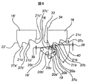
次に図17乃至19を用いて連結板16および駆動機構15を冷蔵庫本体1に組み込んだ例を説明する。   Next, an example in which the connecting plate 16 and the drive mechanism 15 are incorporated in the refrigerator main body 1 will be described with reference to FIGS.

冷蔵庫本体1は箱体105によって形成され、箱体105内に貯蔵室が設けられる。そして、貯蔵室内の左右の側壁105bに沿うように扉枠(スライドレール)101が設けられており、貯蔵室内の後方には補強板102が設けられている。貯蔵室の底壁105aと側壁105bにて形成される空間には容器103が配設され、容器103の上方には容器104が配設される。貯蔵室内の底壁105aには、箱体側にくぼませて形成される凹部106が設けられる。また、容器103には、収納空間側にくぼませて形成されたくぼみ平面部107が設けられる。   The refrigerator body 1 is formed by a box body 105, and a storage room is provided in the box body 105. A door frame (slide rail) 101 is provided along the left and right side walls 105b in the storage chamber, and a reinforcing plate 102 is provided behind the storage chamber. A container 103 is disposed in a space formed by the bottom wall 105 a and the side wall 105 b of the storage chamber, and a container 104 is disposed above the container 103. The bottom wall 105a in the storage chamber is provided with a recess 106 formed by being recessed toward the box. In addition, the container 103 is provided with a recessed flat surface portion 107 formed by being recessed toward the storage space side.

なお、図17は、連結板16を取り付ける補強板を扉枠に取り付けるための補強板構造を示しており、扉枠101に懸架される容器103と容器104は取り外されている。   FIG. 17 shows a reinforcing plate structure for attaching a reinforcing plate for attaching the connecting plate 16 to the door frame, and the container 103 and the container 104 suspended from the door frame 101 are removed.

図示しないが、扉枠101はスライドレールと伴い、冷凍室扉5aの引出し寸法を拡大する。また、扉枠101は冷凍室5の側壁105bに取り付けられたレールの溝内を摺動する。容器103と容器104が冷凍室5よりさらに前方に引出せるスライドレールであった場合、このスライドレールの一方が側壁105bに、他方が扉枠101側に取り付けられることとなる。なお、スライドレールには先に説明したクローザ機構を持たせる。   Although not shown, the door frame 101 is accompanied by the slide rail and expands the drawer size of the freezer compartment door 5a. Further, the door frame 101 slides in a groove of a rail attached to the side wall 105 b of the freezer compartment 5. When the containers 103 and 104 are slide rails that can be drawn further forward than the freezer compartment 5, one of the slide rails is attached to the side wall 105b and the other is attached to the door frame 101 side. The slide rail is provided with the closer mechanism described above.

補強板102は、扉枠101に懸架されており、容器103の後方底部を支持している。また、図18(c)に示すように、補強板102は薄板金属板(一例として2.0mm以下)をプレス加工等によってU字状に形成したものである。補強板102の幅(冷蔵庫本体1に対して前後方向の幅)は、連結板16をネジ108で固定できる幅である。   The reinforcing plate 102 is suspended from the door frame 101 and supports the rear bottom portion of the container 103. Further, as shown in FIG. 18C, the reinforcing plate 102 is formed by forming a thin metal plate (as an example, 2.0 mm or less) into a U shape by pressing or the like. The width of the reinforcing plate 102 (the width in the front-rear direction with respect to the refrigerator main body 1) is a width that allows the connecting plate 16 to be fixed with screws 108.

さらに、この補強板102で扉枠101を接続することにより、扉枠101の横振れを防止している。   Further, by connecting the door frame 101 with the reinforcing plate 102, the door frame 101 is prevented from sideways.

次に図18(a)は、扉枠101に冷凍室容器を取り付けて、冷凍室扉5aを閉め、連結板16と回転板19とが組み合わされた状態を示す図である。また、図18(b)は、図18(a)の要部拡大図である。   Next, FIG. 18A shows a state in which the freezer compartment container is attached to the door frame 101, the freezer compartment door 5a is closed, and the connecting plate 16 and the rotating plate 19 are combined. Moreover, FIG.18 (b) is a principal part enlarged view of Fig.18 (a).

容器103と容器104は、冷凍室扉5aの扉枠101に取り付けられ、冷凍室扉5aが引出されると、容器103と容器104が冷凍室5から前方に引出されるよう構成されている。   The container 103 and the container 104 are attached to the door frame 101 of the freezer compartment door 5a, and when the freezer compartment door 5a is pulled out, the container 103 and the container 104 are configured to be drawn out from the freezer compartment 5 forward.

すなわち、容器103と容器104に設けられた係止部(図示せず)が、扉枠101に設けられた係合孔101aに係止することにより位置決めされ、容器103の後端は補強板102上に載置されている。   That is, a locking portion (not shown) provided in the container 103 and the container 104 is positioned by locking in an engagement hole 101 a provided in the door frame 101, and the rear end of the container 103 is a reinforcing plate 102. It is placed on top.

言い換えると、補強板102のU字形状は、容器103の後方底部をすくう形状に形成されている。また、補強板102の立ち上がりフランジ102aにより、容器103の位置決めを行うようにしている。   In other words, the U-shape of the reinforcing plate 102 is formed in a shape that scoops the rear bottom portion of the container 103. Further, the container 103 is positioned by the rising flange 102a of the reinforcing plate 102.

そして、容器103のフランジ上に容器104の底部が載置される形で取り付けられている。従って、容器104は冷凍室扉5aを引出した時、容器103のフランジ上を後方に摺動し、容器103内の冷凍食品を取り出せる構造としている。   Then, the bottom of the container 104 is mounted on the flange of the container 103. Accordingly, the container 104 has a structure that allows the frozen food in the container 103 to be taken out by sliding backward on the flange of the container 103 when the freezer compartment door 5a is pulled out.

さらに、容器103の後部を、収納空間側、すなわち上方にくぼませて、くぼみ平面部107が形成されている。このくぼみ平面部107は、補強板102へ連結板16を取り付ける際の取り付け寸法を考慮したものである。   Further, the rear portion of the container 103 is recessed toward the storage space, that is, upward, so that a recessed flat surface portion 107 is formed. The indentation flat surface portion 107 takes into account the attachment dimensions when attaching the connecting plate 16 to the reinforcing plate 102.

一方、底壁105aには、箱体側、すなわち下方にくぼませて、凹部106が形成されている。この凹部106は、駆動機構15を底壁105aに取り付ける際の、取り付け寸法を考慮したものである。   On the other hand, a recess 106 is formed in the bottom wall 105a so as to be recessed toward the box, that is, downward. The recess 106 is designed in consideration of the mounting dimensions when the drive mechanism 15 is mounted on the bottom wall 105a.

これにより、連結板16と回転板19とが動作する位置関係で配設される。   Thereby, the connecting plate 16 and the rotating plate 19 are disposed in a positional relationship in which they operate.

本実施例においては、くぼみ平面部107に連結板16を取り付け、凹部106に駆動機構15を設けたことにより、容器103と底壁105aとの隙間を最小限にすることができる。言い換えると、容器103の内容積を確保することができる構成である。   In the present embodiment, the connecting plate 16 is attached to the indentation flat surface portion 107, and the drive mechanism 15 is provided in the concave portion 106, whereby the gap between the container 103 and the bottom wall 105a can be minimized. In other words, the inner volume of the container 103 can be secured.

これにより、駆動機構15の案内ガイド96に対し、連結板16が上下左右位置に対して所定の範囲で出入りするように位置出しすることができる。   As a result, the connecting plate 16 can be positioned with respect to the guide guide 96 of the drive mechanism 15 so as to enter and exit within a predetermined range with respect to the vertical and horizontal positions.

すなわち、駆動機構15は底壁105aに形成される凹部106内に、ネジ等で固定されることにより、部品あるいは組み付け誤差を考慮した公差内に取り付けることができる。   That is, the drive mechanism 15 can be mounted within a tolerance in consideration of parts or assembly errors by being fixed with screws or the like in the recess 106 formed in the bottom wall 105a.

しかし、冷凍室扉5aは、先に説明したように、片持ちの扉枠101に容器103を懸架させるので、扉枠101の冷凍室扉5aに対する直角平行度が狂い、箱体105に対して傾いて閉まることがある。このような状態で連結板16を取り付けた場合、案内ガイド96に連結板16がうまく入って行かなくなってしまうが。そこで本構成は、補強板102が扉枠101の左右振れを防止し、冷凍室扉5aに対する扉枠101の直角平行度を確保するものである。   However, since the freezer compartment door 5a suspends the container 103 on the cantilever door frame 101 as described above, the right-angle parallelism of the door frame 101 to the freezer compartment door 5a is out of order, and the box 105 May tilt and close. If the connecting plate 16 is attached in such a state, the connecting plate 16 does not enter the guide guide 96 successfully. Therefore, in this configuration, the reinforcing plate 102 prevents the door frame 101 from swinging left and right, and ensures the perpendicular parallelism of the door frame 101 with respect to the freezer compartment door 5a.

また、容器103は一般的に樹脂の射出成形等で作られ、肉厚は1mm前後である。そのため、収納する食品の量によっては容器103の底は変形するおそれがある。具体的には、容器の底壁が下方にたわむ。そこで本構成は、補強板102が容器103を支えることで、たわみを防止できる。   The container 103 is generally made by resin injection molding or the like and has a thickness of about 1 mm. Therefore, the bottom of the container 103 may be deformed depending on the amount of food to be stored. Specifically, the bottom wall of the container bends downward. Therefore, in this configuration, the reinforcing plate 102 supports the container 103, so that the deflection can be prevented.

さらに、補強板102の立ち上がりフランジ102aは、容器103が扉枠101から扉開閉時の衝撃で後方に飛び出してしまうのを防止する役目を果たし、連結板16が駆動機構15の案内ガイド96に安定して出入りするのを確保する役目も果たしている。   Further, the rising flange 102a of the reinforcing plate 102 serves to prevent the container 103 from jumping out rearward from the door frame 101 due to an impact when the door is opened and closed, and the connecting plate 16 is stable to the guide guide 96 of the drive mechanism 15. It also plays a role in ensuring that it enters and exits.

次に図19において、凹部106には、凹形状に沿うようにして下ケース109bが配設されている。下ケース109bは上方が開放された箱形状であり、この開放部を閉鎖するように上ケース109aが配設される。下ケース109bと上ケース109aとにより形成された空間には、モータ24と、図4に示した歯車列が配設される。   Next, in FIG. 19, a lower case 109b is disposed in the concave portion 106 so as to follow the concave shape. The lower case 109b has a box shape with the upper part opened, and the upper case 109a is disposed so as to close the open part. In the space formed by the lower case 109b and the upper case 109a, the motor 24 and the gear train shown in FIG. 4 are disposed.

下ケース109bのフランジ109cは、箱体105の底壁105aより上方に突出するように構成される。すなわち、上ケース109aと下ケース109bとの合わせ面は、底壁105aよりも上方に位置するように配設される。   The flange 109c of the lower case 109b is configured to protrude above the bottom wall 105a of the box 105. That is, the mating surface of the upper case 109a and the lower case 109b is disposed so as to be positioned above the bottom wall 105a.

これにより、冷凍室5の下方に水が溜まった場合でも、下ケース109bの内部に浸入するのを防止できる。すなわち、冷凍室5の下部に溜まった水の下ケース109b内への浸入による、駆動機構15の損傷を防止できる構造である。   Thereby, even when water accumulates below the freezer compartment 5, it can be prevented from entering the inside of the lower case 109b. That is, it is a structure that can prevent the drive mechanism 15 from being damaged by the penetration of the water accumulated in the lower part of the freezer compartment 5 into the lower case 109b.

また、下ケース109aと上ケース109bを合わせることで形成された空間は、内部に内空間110aが形成され、この内空間110aの外周に外空間110bが区画形成されるように構造される。具体的に内空間110aは、下ケース109aの底壁から上方に延伸した仕切壁が、モータ24と、図4に示した歯車列を囲繞するようにして形成されている。外空間には、図示しないネジ孔が穿設され、上ケース109a、下ケース109bが、底壁105aに対して位置決めして固定できるように構成される。   The space formed by combining the lower case 109a and the upper case 109b is structured such that an inner space 110a is formed inside, and an outer space 110b is defined on the outer periphery of the inner space 110a. Specifically, the inner space 110a is formed such that a partition wall extending upward from the bottom wall of the lower case 109a surrounds the motor 24 and the gear train shown in FIG. Screw holes (not shown) are formed in the outer space so that the upper case 109a and the lower case 109b can be positioned and fixed with respect to the bottom wall 105a.

さらに好ましくは、上ケース109aと下ケース109bとの合わせ面に、シリコン等を塗布し、合わせ面の隙間を塞ぐ構成とする。これにより、ケース内部への浸入をより防止できる。   More preferably, silicon or the like is applied to the mating surface of the upper case 109a and the lower case 109b to close the gap between the mating surfaces. Thereby, the penetration | invasion to the inside of a case can be prevented more.

また、上ケース109aと下ケース109bの合わせ面よりも上方に、モータのリード線引き出し部が設けられる。すなわち、底壁105aよりも上方にリード線引出し部が設けられるので、ケース内部への浸入をより防止できる。   A lead wire lead-out portion for the motor is provided above the mating surface of the upper case 109a and the lower case 109b. That is, since the lead wire lead-out portion is provided above the bottom wall 105a, the intrusion into the case can be further prevented.

さらに、本発明による扉開閉装置を冷凍室5および野菜室6の両方に設けた場合の動作について説明する。図2に示すように、野菜室6が最も下段の底面近傍にあり、その上段に冷凍室5が設けられているものとする。   Furthermore, the operation when the door opening and closing device according to the present invention is provided in both the freezer compartment 5 and the vegetable compartment 6 will be described. As shown in FIG. 2, it is assumed that the vegetable compartment 6 is in the vicinity of the bottom of the lowermost stage, and the freezer compartment 5 is provided on the upper stage.

使用者が冷蔵庫1の正面に立って冷凍室5を開いたとき、冷凍室5が電動で開く量は例えば15cmないし20cm程度であるとすれば、開いた際に冷凍庫の内部を開口部から見渡すことができるので好適である。一方、野菜室6においては、野菜室6が床面近傍にあるため、冷凍室と同様に開くとすれば、開いた際に野菜室6の扉の下端がユーザのつま先に当たる恐れがある。   When the user stands in front of the refrigerator 1 and opens the freezer 5, if the freezer 5 is electrically opened for example about 15 cm to 20 cm, the inside of the freezer is looked over from the opening when opened. This is preferable. On the other hand, in the vegetable compartment 6, since the vegetable compartment 6 is in the vicinity of the floor, if it is opened in the same manner as the freezer compartment, the lower end of the door of the vegetable compartment 6 may hit the user's toe when opened.

そこで、下段にある野菜室6は、上段にある冷凍室5と比べて開く際の開き速度を遅くすることと、さらには開き量を例えば10cm以内と小さくすることが安全上望ましい。   Therefore, it is desirable in terms of safety that the vegetable room 6 in the lower stage has a lower opening speed than the freezer room 5 in the upper stage, and further the opening amount is made smaller, for example, within 10 cm.

なお、上記の説明では野菜室が冷凍室よりも下端にあるものとして説明したが、冷凍室が野菜室よりも下段にある場合には、冷凍室の開き量ないし開き速度を野菜室よりも小とすることが望ましい。   In the above description, the vegetable room is described as being at the lower end of the freezer room. However, when the freezer room is at a lower stage than the vegetable room, the opening amount or opening speed of the freezer room is smaller than that of the vegetable room. It is desirable that

本発明によれば、冷蔵庫の引出し扉の開き力を低減して軽快に扉を開放することを可能とするとともに、いわゆる半ドア状態から自動的に扉を閉鎖して省エネ効果を向上させることができる。   According to the present invention, it is possible to open the door lightly by reducing the opening force of the drawer door of the refrigerator, and to improve the energy saving effect by automatically closing the door from a so-called half-door state. it can.

すなわち、冷凍室5を閉鎖状態から開き始める際には駆動軸18の最も近傍に配置された第一の駆動ピン20aが連結板16を押し出して駆動することで、低速であるが大きな力を出してマグネットパッキンを引き剥がす。引き続き第一の駆動ピン20aよりも遠方に設けられた第二の駆動ピン20bが連結板16を押し出して中程度の速度で中程度の力を出して駆動することでクローザ13の引込力に抗して開き動作を継続して冷凍室5を加速する。さらに引き続いて第二の駆動ピン20bよりも駆動軸18から遠方に設けられた第三の駆動ピン20cが連結板16を押し出して、力は小さいが高速で駆動することによって冷凍室5をさらに加速することができるので、冷凍室5の開き動作を確実に行うのに都合が良く、確実に開き動作を行うことができる、という効果がある。   That is, when the freezer compartment 5 starts to be opened from the closed state, the first drive pin 20a disposed closest to the drive shaft 18 pushes and drives the connecting plate 16 to generate a large force at a low speed. Remove the magnetic packing. Subsequently, the second drive pin 20b provided farther than the first drive pin 20a pushes the connecting plate 16 and drives it with a medium force at a medium speed, thereby resisting the pulling force of the closer 13. Then, the freezing chamber 5 is accelerated by continuing the opening operation. Subsequently, the third drive pin 20c provided farther from the drive shaft 18 than the second drive pin 20b pushes the connecting plate 16, and further accelerates the freezer compartment 5 by driving at a high speed with a small force. Therefore, there is an effect that it is convenient to reliably perform the opening operation of the freezer compartment 5 and can be reliably performed.

さらに、冷凍室5が完全には閉じずに所謂半ドア状態になっていたとしても、回転板
19を冷凍室5を開く場合とは反対方向に回転させることによって、連結板16に対して冷凍室5を閉じる方向の力を加えて閉じることができるので、半ドアを防止して省エネ効果が得られる。上記の閉鎖動作を複数回繰り返すことで半ドア防止をさらに確実にして、信頼性を向上できる。
Furthermore, even if the freezer compartment 5 is not completely closed and is in a so-called half-door state, the rotating plate 19 is rotated in the opposite direction to the case where the freezer compartment 5 is opened, thereby freezing the connecting plate 16. Since the chamber 5 can be closed by applying a force in the closing direction, a half-door is prevented and an energy saving effect is obtained. By repeating the above closing operation a plurality of times, half door prevention can be further ensured and reliability can be improved.

さらに冷凍室を閉じ始める開き量35が扉厚さ71よりも小となるようにすれば、指などを挟まれる恐れがなく安全性を高めることができる。   Furthermore, if the opening amount 35 for starting to close the freezer compartment is made smaller than the door thickness 71, there is no fear that a finger or the like is caught, and safety can be improved.

手動で開閉する場合には、本発明による扉開閉機構は冷蔵庫本体に設けられた駆動機構と、引出し扉側と一体に設けられた連結板とは接触しないので、引出し開閉の際に使用者による手動動作を妨げたり、開閉動作が重くなったり、等の現象が生じないので使い勝手がよく、また万一の故障の際にも使用者の使い勝手を損なうことがない。   When manually opening and closing, the door opening and closing mechanism according to the present invention does not contact the drive mechanism provided in the refrigerator body and the connecting plate provided integrally with the drawer door side, so that the user can open and close the drawer. It does not impede manual operation or increase the opening / closing operation, so that it is easy to use and does not impair the user's usability in the event of a failure.

また、片持ちの扉枠101に懸架される容器を安定して位置決めする補強板を設け、この補強板に連結部材を取り付けることにより、連結部材と駆動機構との係合状態が確保でき、信頼性を向上できる。   In addition, by providing a reinforcing plate for stably positioning the container suspended on the cantilever door frame 101 and attaching the connecting member to the reinforcing plate, the engagement state between the connecting member and the drive mechanism can be secured, and the reliability Can be improved.

また、駆動機構の配設されるケースにおいて、下ケース109bのフランジを冷凍室または野菜室の底壁よりも上方に突出させることで、ケース内への浸入による駆動機構の損傷を防止することができ、信頼性を向上できる。   Further, in the case where the drive mechanism is arranged, the flange of the lower case 109b protrudes above the bottom wall of the freezer compartment or vegetable compartment, thereby preventing the drive mechanism from being damaged due to entering the case. Can improve reliability.

なお、本実施例においては扉開閉装置10が冷凍室5ないし野菜室6の引出し扉に設けられている例を示したが、本実施例に限定されるものではなく冷蔵室扉2の回転式の扉に設けられるものであっても同様な効果が得られる。   In the present embodiment, the door opening / closing device 10 is provided on the drawer door of the freezer compartment 5 or the vegetable compartment 6. However, the present invention is not limited to this embodiment, and the refrigerating compartment door 2 is rotatable. Even if it is provided on the door, the same effect can be obtained.

また、本実施例においては冷蔵庫に扉開閉装置を備えた構成について説明したが、冷蔵庫に限定されるものではなく、例えば文書類を保管するファイルキャビネットや、手前に引き出して使用する流し台組み込み型の食器洗い乾燥機、などの引き出し式の機器に適用でき、その場合にも本発明にて説明したと同様な効果がある。   Further, in the present embodiment, the configuration in which the refrigerator is provided with the door opening / closing device has been described, but it is not limited to the refrigerator, for example, a file cabinet for storing documents or a sink built-in type that is pulled out and used for the front. The present invention can be applied to a drawer-type device such as a dishwasher, and in that case, the same effect as described in the present invention can be obtained.

本実施例においては、駆動機構15は平歯車のみによって構成される例を示したが、平歯車に限定されるものではなく、ウォームギヤを用いた構成であってもよい。   In the present embodiment, an example in which the drive mechanism 15 is configured by only a spur gear is shown, but the drive mechanism 15 is not limited to a spur gear, and may be configured by using a worm gear.

またさらに、駆動ピン20は本実施例のような円筒状のピンではなく、回転式のローラであってもよい。   Furthermore, the drive pin 20 may be a rotary roller instead of the cylindrical pin as in the present embodiment.

本発明による冷蔵庫の構成を示す斜視図。The perspective view which shows the structure of the refrigerator by this invention. 本発明による冷蔵庫の構成を示す断面図。Sectional drawing which shows the structure of the refrigerator by this invention. 本発明による冷蔵庫の引出し扉開閉装置の構成を示す平面図。The top view which shows the structure of the drawer door opening / closing apparatus of the refrigerator by this invention. 本発明による冷蔵庫の引出し扉開閉装置の構成を示す斜視図。The perspective view which shows the structure of the drawer door opening / closing apparatus of the refrigerator by this invention. 本発明による冷蔵庫の引出し扉開閉装置の構成を示す斜視図。The perspective view which shows the structure of the drawer door opening / closing apparatus of the refrigerator by this invention. 本発明による冷蔵庫の引出し扉開閉装置の開き動作を説明する図。The figure explaining opening operation | movement of the drawer door opening / closing apparatus of the refrigerator by this invention. 本発明による冷蔵庫の引出し扉開閉装置の閉じ動作を説明する図。The figure explaining closing operation | movement of the drawer door opening / closing apparatus of the refrigerator by this invention. 本発明による冷蔵庫の引出し扉開閉装置の停止時の位置を説明する図。The figure explaining the position at the time of the stop of the drawer door opening / closing apparatus of the refrigerator by this invention. 本発明による冷蔵庫の引出し扉開閉装置の制御系の構成を示すプロック図。The block diagram which shows the structure of the control system of the drawer door opening / closing apparatus of the refrigerator by this invention. 本発明による冷蔵庫の引出し扉開閉装置の開き動作の際の制御手順を示す流れ図。The flowchart which shows the control procedure in the case of opening operation | movement of the drawer door opening / closing apparatus of the refrigerator by this invention. 本発明による冷蔵庫の引出し扉開閉装置の閉じ動作の際の制御手順を示す流れ図。The flowchart which shows the control procedure in the case of the closing operation | movement of the drawer door opening / closing apparatus of the refrigerator by this invention. 本発明による冷蔵庫の引出し扉開閉装置の別の構成を示す図The figure which shows another structure of the drawer door opening / closing apparatus of the refrigerator by this invention. 図3に示す回転部材を中心とする各部材の取り付け状態を説明する駆動機構の斜視図。The perspective view of the drive mechanism explaining the attachment state of each member centering on the rotation member shown in FIG. 扉開閉装置の動作を説明するための上面図。The top view for demonstrating operation | movement of a door opening / closing apparatus. 図15の扉開閉装置の側面図。The side view of the door opening / closing apparatus of FIG. 図15の扉開閉装置の正面図。The front view of the door opening / closing apparatus of FIG. 本発明による連結板を取り付ける補強板を扉枠に取り付けるための補強板構造を示す要部上面図。The principal part top view which shows the reinforcement board structure for attaching the reinforcement board which attaches the connection board by this invention to a door frame. 図18に示す扉枠に冷凍室容器を取り付け、冷凍室扉を閉め、連結板と回転板とが組み合わされた状態を示す要部縦断面図。The principal part longitudinal cross-sectional view which shows the state which attached the freezer compartment container to the door frame shown in FIG. 18, closed a freezer compartment door, and combined the connection plate and the rotating plate. 図19に示す駆動機構を冷凍室底面に取り付けた状態を説明する要部拡大図。The principal part enlarged view explaining the state which attached the drive mechanism shown in FIG. 19 to the freezer compartment bottom face. 本発明による冷蔵庫の引出し扉開閉装置の開き動作を説明する図。The figure explaining opening operation | movement of the drawer door opening / closing apparatus of the refrigerator by this invention. 本発明による冷蔵庫の引出し扉開閉装置の開スイッチの構成を示す図。The figure which shows the structure of the open switch of the drawer door opening / closing apparatus of the refrigerator by this invention. 本発明による冷蔵庫の引出し扉開閉装置の開スイッチの構成を示す拡大図。The enlarged view which shows the structure of the open switch of the drawer door opening / closing apparatus of the refrigerator by this invention.

符号の説明Explanation of symbols

1 冷蔵庫本体
2 冷蔵室
2a 冷蔵室扉
3 切り替え室
3a 切り替え室扉
4 製氷室
5 冷凍室
5a 冷凍室扉
6 野菜室
6a 野菜室扉
7 操作表示部
8 開スイッチ
10 扉開閉装置
11 スライドレール
12 容器
13 クローザ
14 マグネットパッキン
15 駆動機構
15a ベース板
16 連結板
16a 摺動部
17 ドア検知
17a 第一のドア検知
17b 第二のドア検知
18 駆動軸
19 回転板
20 駆動ピン
20a 第一の駆動ピン
20b 第二の駆動ピン
20c 第三の駆動ピン
20d 第四の駆動ピン
21 受け面
21a 第一の受け面
21b 第二の受け面
21c 第三の受け面
21d 第四の受け面
22 戻し面
23 開き方向
24 モータ
25 モータピニオン
26 アイドラ
27 アイドラピオン
28 アイドラ
29 アイドラピオン
30 駆動ギヤ
31 トルク制限手段
32 回転検知手段
33 移動量
34 引込位置
35 開き量
36 矢印
37a 第一の先端
37b 第二の先端
37c 第三の先端
38 隙間
39 隙間
40 原点範囲
41 制御回路
42 電源
70 報知手段
71 扉厚さ
72 扉間隙間
73 最大開き量
74 惰性開き量
75 接点
76 カム
77 回転中心
78 カム外周
79 カム受け板
80 回転方向
81 矢印
82 カム半径
83 周速
84 開き速度
85 滑り速度
86 接点
87 枠体
88 押しボタン
89 押し棒
90 戻しスプリング
91 押し量
92 スイッチ本体
93 プランジャ
94 配線
95 磁石
96 案内ガイド
96a、96b 突片
97 ホールIC
98 ホールIC
99 磁石
100 磁石
101 扉枠
101a 係合孔
102 補強板
102a 立ち上がりフランジ
103 容器(a)
104 容器(b)
105 箱体
105a 底壁
105b 側壁
106 凹部
107 くぼみ平面部
108 ネジ
109 ケース
109a 上ケース
109b 下ケース
109c フランジ
110a 内空間
110b 外空間
DESCRIPTION OF SYMBOLS 1 Refrigerator body 2 Refrigeration room 2a Refrigeration room door 3 Switching room 3a Switching room door 4 Ice making room 5 Freezing room 5a Freezing room door 6 Vegetable room 6a Vegetable room door 7 Operation display part 8 Open switch 10 Door opening and closing device 11 Slide rail 12 Container 13 Closer 14 Magnet packing 15 Drive mechanism 15a Base plate 16 Connecting plate 16a Sliding part 17 Door detection 17a First door detection 17b Second door detection 18 Drive shaft 19 Rotating plate 20 Drive pin 20a First drive pin 20b First Second drive pin 20c Third drive pin 20d Fourth drive pin 21 Receiving surface 21a First receiving surface 21b Second receiving surface 21c Third receiving surface 21d Fourth receiving surface 22 Return surface 23 Opening direction 24 Motor 25 motor pinion 26 idler 27 idler pinion 28 idler 29 idler pinion 30 drive gear 31 torque limit Means 32 Rotation detection means 33 Movement amount 34 Retraction position 35 Opening amount 36 Arrow 37a First tip 37b Second tip 37c Third tip 38 Clearance 39 Clearance 40 Origin range 41 Control circuit 42 Power supply 70 Notification means 71 Door thickness 72 Door-to-door clearance 73 Maximum opening amount 74 Inertial opening amount 75 Contact point 76 Cam 77 Center of rotation 78 Cam outer periphery 79 Cam receiving plate 80 Direction of rotation 81 Arrow 82 Cam radius 83 Peripheral speed 84 Opening speed 85 Sliding speed 86 Contact 87 Frame body 88 Push Button 89 Push bar 90 Return spring 91 Push amount 92 Switch body 93 Plunger 94 Wire 95 Magnet 96 Guide guide 96a, 96b Projection piece 97 Hall IC
98 Hall IC
99 Magnet 100 Magnet 101 Door frame 101a Engagement hole 102 Reinforcement plate 102a Standing flange 103 Container (a)
104 Container (b)
105 Box 105a Bottom wall 105b Side wall 106 Recess 107 Recess flat surface 108 Screw 109 Case 109a Upper case 109b Lower case 109c Flange 110a Inner space 110b Outer space

Claims (6)

冷蔵庫本体に区画形成された貯蔵室と、
前記貯蔵室に設けられ開閉可能な引出し扉と、
前記貯蔵室に設けられ前記引出し扉を開閉させる駆動手段と、
前記駆動手段にて回転可能であり、且つ回転方向に向かって回転中心からの距離を除々に変化させた位置に複数の駆動伝達部材が設けられた回転部材と、
前記引出し扉又は該引出し扉とともに前後方向に引出すことができる収納部の下面に設けられ、且つ前記駆動伝達部材から動力が伝達されて前記回転部材の回転運動を直線運動に変換させる連結部材と、
前記引出し扉が閉鎖されていることを検知する扉閉検知手段を備え
記扉閉検知手段が前記引出し扉が閉鎖状態であることを検知するまで、所定回数、前記駆動伝達部材が前記連結部材に当接するように前記回転部材を回転駆動させることを特徴とする扉駆動装置を備えた冷蔵庫。
A storage compartment defined in the refrigerator body;
A drawer door provided in the storage room and capable of opening and closing;
Drive means provided in the storage chamber for opening and closing the drawer door;
A rotating member provided with a plurality of drive transmission members at a position that can be rotated by the driving means and gradually change the distance from the rotation center in the rotation direction ;
A connecting member that is provided on the lower surface of the storage portion that can be pulled out in the front-rear direction together with the drawer door or the drawer door, and that transmits power from the drive transmission member to convert the rotational motion of the rotating member into linear motion ;
Comprising door closing detection means for detecting that the drawer door is closed ;
Door previous Kitobira閉detecting means, wherein the causing the rotary member rotatably driven so as to detect that the drawer door is closed, a predetermined number of times, the drive transmission member is brought into contact with said connecting member A refrigerator equipped with a driving device.
請求項1に記載の冷蔵庫において、前記扉閉検知手段が前記引出し扉が閉鎖状態であることを検知するまで、前記駆動伝達部材が前記連結部材に当接するように前記回転部材を所定時間回転駆動させて、前記駆動伝達部材が前記連結部材と離反するように前記回転部材を所定位置まで回転駆動させることを所定回数繰り返す扉駆動装置を備えた冷蔵庫。 2. The refrigerator according to claim 1, wherein the rotation member is driven to rotate for a predetermined time so that the drive transmission member contacts the connection member until the door closing detection unit detects that the drawer door is in a closed state. A refrigerator including a door drive device that repeats a predetermined number of times to rotate the rotating member to a predetermined position so that the drive transmission member is separated from the connecting member . 請求項2に記載の冷蔵庫において、前記回転部材の回転位置を検知する回転検知手段を備え、前記回転検知手段が前記回転部材が所定位置にあることを検知するまで、前記駆動伝達部材が前記連結部材から離反する方向に前記回転部材を回転駆動させることを特徴とする扉駆動装置を備えた冷蔵庫。 The refrigerator according to claim 2, further comprising a rotation detection unit that detects a rotation position of the rotation member, wherein the drive transmission member is connected to the connection until the rotation detection unit detects that the rotation member is in a predetermined position. refrigerator having a door drive device for causing said rotary member in a direction away from the member rotationally driven. 請求項1に記載の冷蔵庫において、扉が開放していることを報知する報知手段を備え、前記扉閉検知手段が前記引出し扉が閉鎖状態であることを検知するまで、前記駆動伝達部材が前記連結部材に当接するように前記回転部材を所定時間回転駆動させて、前記駆動伝達部材が前記連結部材と離反するように前記回転部材を所定位置まで回転駆動させることを所定回数繰り返して、報知手段を作動させることを特徴とする扉駆動装置を備えた冷蔵庫。 The refrigerator according to claim 1, further comprising an informing means for informing that the door is open, wherein the drive transmission member is in the state until the door closing detecting means detects that the drawer door is in a closed state. connected the rotating member causes the rotationally driven a predetermined time so as to contact the member, is repeated a predetermined number of times that the rotationally driving the rotary member such that the drive transmission member is separated and the connecting member to a predetermined position, the notification means A refrigerator provided with a door driving device. 請求項1又は2に記載の冷蔵庫において、前記貯蔵室の底壁に凹形状に設けられた凹部と、前記凹部に配設され上方が開口した下ケースと、前記下ケースの開口を閉鎖するように下ケースと接合される上ケースとを備え、前記上ケースにはリード線引出し部が設けられ、前記上ケースと前記下ケースとで形成される空間に前記駆動装置が配設され、前記上ケースと前記下ケースの接合部は前記貯蔵室の底壁よりも上方にあることを特徴とする扉駆動装置を備えた冷蔵庫。 The refrigerator according to claim 1 or 2, wherein a concave portion provided in a concave shape on the bottom wall of the storage chamber, a lower case disposed in the concave portion and opened upward, and an opening of the lower case are closed. An upper case joined to the lower case, the upper case is provided with a lead wire lead-out portion, and the driving device is disposed in a space formed by the upper case and the lower case. A refrigerator provided with a door driving device, wherein a joint between the case and the lower case is located above the bottom wall of the storage chamber. 請求項5に記載の冷蔵庫において、前記下ケース内には上方に延伸した仕切壁を有し、前記仕切壁は前記駆動装置を囲繞するように構成されることを特徴とする扉駆動装置を備えた冷蔵庫。   6. The refrigerator according to claim 5, further comprising a partition wall extending upward in the lower case, wherein the partition wall is configured to surround the drive device. Fridge.
JP2007031033A 2007-02-09 2007-02-09 refrigerator Expired - Fee Related JP4384189B2 (en)

Priority Applications (2)

Application Number Priority Date Filing Date Title
JP2007031033A JP4384189B2 (en) 2007-02-09 2007-02-09 refrigerator
CNB2007101403847A CN100545559C (en) 2007-02-09 2007-08-10 Refrigerator

Applications Claiming Priority (1)

Application Number Priority Date Filing Date Title
JP2007031033A JP4384189B2 (en) 2007-02-09 2007-02-09 refrigerator

Publications (2)

Publication Number Publication Date
JP2008196750A JP2008196750A (en) 2008-08-28
JP4384189B2 true JP4384189B2 (en) 2009-12-16

Family

ID=39755859

Family Applications (1)

Application Number Title Priority Date Filing Date
JP2007031033A Expired - Fee Related JP4384189B2 (en) 2007-02-09 2007-02-09 refrigerator

Country Status (2)

Country Link
JP (1) JP4384189B2 (en)
CN (1) CN100545559C (en)

Families Citing this family (5)

* Cited by examiner, † Cited by third party
Publication number Priority date Publication date Assignee Title
CN106355756B (en) * 2016-09-27 2022-08-05 内蒙古智牧溯源技术开发有限公司 Freezing formula automatic vending machine
CN107348925A (en) * 2017-09-08 2017-11-17 佛山市顺德区美的洗涤电器制造有限公司 Runner assembly and dish-washing machine
CN107830313B (en) * 2017-12-14 2024-01-26 重庆市中美电力设备有限公司 Pull type energy-saving control integrated box
CN109780799B (en) * 2018-12-28 2022-11-01 海尔智家股份有限公司 Refrigerator with a door
KR20210008708A (en) * 2019-07-15 2021-01-25 엘지전자 주식회사 Refrigerator and control method thereof

Family Cites Families (3)

* Cited by examiner, † Cited by third party
Publication number Priority date Publication date Assignee Title
JP2001111238A (en) * 1999-10-08 2001-04-20 Sumitomo Metal Electronics Devices Inc Via-hole connection strength measurement device and measurement method
JP2002267352A (en) * 2001-03-06 2002-09-18 Sanyo Electric Co Ltd Refrigerator
JP4076528B2 (en) * 2004-08-30 2008-04-16 日立アプライアンス株式会社 Refrigerator door closing device

Also Published As

Publication number Publication date
JP2008196750A (en) 2008-08-28
CN100545559C (en) 2009-09-30
CN101240971A (en) 2008-08-13

Similar Documents

Publication Publication Date Title
JP4247279B2 (en) refrigerator
JP4247278B2 (en) refrigerator
JP4384187B2 (en) refrigerator
JP4384190B2 (en) Refrigerator and refrigerator door opening and closing device
JP4384189B2 (en) refrigerator
JP4861926B2 (en) refrigerator
JP4993946B2 (en) Drawing device
JP4127312B2 (en) refrigerator
JP4477646B2 (en) refrigerator
JP4366410B2 (en) refrigerator
JP6348588B2 (en) Furniture drive
JP4374380B2 (en) refrigerator
JP4988483B2 (en) Pull-out equipment
JP4384191B2 (en) refrigerator
JP4384188B2 (en) refrigerator
JP3524815B2 (en) Motion assist device and refrigerator
JP2000291333A (en) Operation support device
JP4117336B1 (en) Pull-out equipment
JP3604947B2 (en) Motion assist device and door opening / closing mechanism
JP3519313B2 (en) Motion assist device and motion assist device for refrigerator
JP2006118858A (en) Refrigerator
EP1630503B1 (en) Refrigerator having basket lift apparatus
JP4117337B1 (en) Door opening and closing device
JP3591628B2 (en) Motion assist device and motion assist device for refrigerator
JP3537322B2 (en) Drawer drive

Legal Events

Date Code Title Description
A621 Written request for application examination

Free format text: JAPANESE INTERMEDIATE CODE: A621

Effective date: 20081226

A521 Written amendment

Free format text: JAPANESE INTERMEDIATE CODE: A523

Effective date: 20081226

A131 Notification of reasons for refusal

Free format text: JAPANESE INTERMEDIATE CODE: A131

Effective date: 20090303

A521 Written amendment

Free format text: JAPANESE INTERMEDIATE CODE: A523

Effective date: 20090427

TRDD Decision of grant or rejection written
A01 Written decision to grant a patent or to grant a registration (utility model)

Free format text: JAPANESE INTERMEDIATE CODE: A01

Effective date: 20090915

A01 Written decision to grant a patent or to grant a registration (utility model)

Free format text: JAPANESE INTERMEDIATE CODE: A01

A61 First payment of annual fees (during grant procedure)

Free format text: JAPANESE INTERMEDIATE CODE: A61

Effective date: 20090924

FPAY Renewal fee payment (event date is renewal date of database)

Free format text: PAYMENT UNTIL: 20121002

Year of fee payment: 3

R150 Certificate of patent or registration of utility model

Free format text: JAPANESE INTERMEDIATE CODE: R150

FPAY Renewal fee payment (event date is renewal date of database)

Free format text: PAYMENT UNTIL: 20131002

Year of fee payment: 4

LAPS Cancellation because of no payment of annual fees