JP4384186B2 - Construction method of double floor structure, partition wall support member and double floor structure - Google Patents
Construction method of double floor structure, partition wall support member and double floor structure Download PDFInfo
- Publication number
- JP4384186B2 JP4384186B2 JP2007025315A JP2007025315A JP4384186B2 JP 4384186 B2 JP4384186 B2 JP 4384186B2 JP 2007025315 A JP2007025315 A JP 2007025315A JP 2007025315 A JP2007025315 A JP 2007025315A JP 4384186 B2 JP4384186 B2 JP 4384186B2
- Authority
- JP
- Japan
- Prior art keywords
- partition wall
- floor
- base
- support member
- vibration
- Prior art date
- Legal status (The legal status is an assumption and is not a legal conclusion. Google has not performed a legal analysis and makes no representation as to the accuracy of the status listed.)
- Active
Links
Images


Description
本発明は、集合住宅等の建物において床先行工法により構築される二重床構造、この二重床構造の施工方法、およびこれらに用いられる間仕切り壁支持部材に関する。 The present invention relates to a double floor structure constructed by a floor prior construction method in a building such as an apartment house, a construction method of the double floor structure, and a partition wall support member used in these structures.
集合住宅の床構造としては、建物躯体の床面から所定高さの間隔を空けて床材を設置してなる二重床構造が多く採用される。 As a floor structure of an apartment house, a double floor structure in which floor materials are installed at a predetermined height from the floor of a building frame is often used.
二重床構造の施工方法としては、いわゆる壁先行工法が一般的に知られている。壁先行工法は、例えば図9に示すように、建物躯体152の床面154に間仕切り壁135を立設した後、複数の間仕切り壁135間に跨って床材130を所定高さに設置する工法である。壁先行工法により構築された二重床構造では、間仕切り壁135が建物躯体152に直接支持されるため、間仕切り壁135の支持強度を十分に確保できる利点を有する。
A so-called wall advance construction method is generally known as a construction method of a double floor structure. For example, as shown in FIG. 9, the wall leading construction method is a construction method in which the
しかし、壁先行工法では、間仕切り壁で小さく区切られた空間において、出隅や入り隅が多い状態で床材を施工しなければならず、部屋隅では際根太の取付けが必要となる。そのため、施工が著しく煩雑となってしまう。また、狭い空間で床材を施工することに伴い、歩留りが悪くなり、材料コストの高騰を招いてしまう。さらに、リフォームの際、間仕切り壁の配置を変更するためには、間仕切り壁のみならず床材も取り外す必要があるため、リフォーム時の施工が煩雑となる欠点も有する。 However, in the wall advance construction method, the floor material must be constructed with a large number of protruding corners and entering corners in a space that is partitioned by a partition wall, and it is necessary to attach a joist at the corner of the room. Therefore, the construction becomes extremely complicated. Moreover, with the construction of the flooring in a narrow space, the yield deteriorates and the material cost increases. Furthermore, since it is necessary to remove not only the partition walls but also the flooring material in order to change the arrangement of the partition walls at the time of renovation, there is a disadvantage that the construction at the time of renovation becomes complicated.
一方、二重床構造の施工方法として、建物躯体の床面から所定高さの間隔を空けて床材を設置した後に、床材の上面に間仕切り壁を立設してなる、いわゆる床先行工法が提案されている。 On the other hand, as a construction method of the double floor structure, after installing the flooring at a predetermined height from the floor of the building frame, a so-called floor leading construction method, in which a partition wall is erected on the upper surface of the flooring Has been proposed.
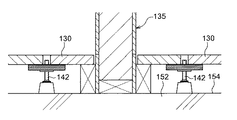
床先行工法としては、間仕切り壁の設置部分において、床材を下側から支持する補強用の支持脚等の支持部材を予め設置しておき、支持部材が設置された床材部分に間仕切り壁を立設する工法や、図10に示すように、床材130を支持する支持部材142の設置個数を通常の2倍以上として、支持部材142のピッチを小さくすることで床剛性を高めた上で、床材130上に間仕切り壁135を立設する工法が、従来から採用されている。
As the floor prior construction method, in the installation part of the partition wall, a support member such as a support leg for reinforcement that supports the floor material from the lower side is installed in advance, and the partition wall is attached to the floor material part where the support member is installed. As shown in FIG. 10, the number of
しかし、前者の工法では、床材の設置前に、床材を下側から支持する補強用の支持部材を、間仕切り壁の設置部分に正確に配置する必要があり、施工が煩雑となる欠点を有する。また、支持部材の非設置部分に間仕切り壁を立設できないため、床材の設置後に間仕切り壁を自由に配置できず、設計の自由度が低くなってしまう。一方、後者の工法では、補強用の支持部材の設置個数が多いため、施工性の悪化と材料コストの増大を招く欠点を有する。また、両者とも、間仕切り壁が床材上に立設されるため、床衝撃音発生時の振動が床材から間仕切り壁を通して階下へ伝達しやすい欠点を有する。 However, in the former method, before installing the flooring, it is necessary to accurately dispose the reinforcing support member that supports the flooring from the lower side on the installation part of the partition wall. Have. Moreover, since a partition wall cannot be erected in the non-installation part of a support member, a partition wall cannot be freely arrange | positioned after installation of a flooring, and the freedom degree of design will become low. On the other hand, the latter construction method has a drawback that the workability is deteriorated and the material cost is increased because the number of support members for reinforcement is large. In both cases, since the partition wall is erected on the flooring material, the vibration at the time of floor impact sound is easily transmitted from the flooring material to the floor through the partitioning wall.
このような問題に鑑みて、特許文献1では、床先行工法における施工性を改善するための技術が提案されている。
特許文献1の技術では、間仕切り壁の下端部に沿って配置される長尺の基材と、この基材の下面より下方へ突出した支持脚とを備えた間仕切り壁支持部材が用いられる。間仕切り壁支持部材は、二重床の床材が設置された後に設置される。具体的には、間仕切り壁支持部材を設置する際、先ず、床材の所定箇所に複数の開口部を穿設し、これらの開口部に、間仕切り壁支持部材の支持脚を上側から挿通させて、支持脚の下端を建物躯体の床面に当接させ、間仕切り壁支持部材の基材を床材上面に載置する。かかる技術によれば、間仕切り壁支持部材の位置決めを床材の設置後に行うことができ、間仕切り壁支持部材を必要以上に多く設置することを回避できるため、床先行工法の施工性を従来よりも大幅に改善できる。また、床材の設置後に、間仕切り壁支持部材および間仕切り壁の設置場所を任意に決定できるため、設計の自由度を高めることができる。さらに、リフォームの際、床材を取り外さなくても、間仕切り壁支持部材および間仕切り壁の配置を変更できるため、リフォーム時の施工性が良好となる。 In the technique of Patent Document 1, a partition wall support member including a long base material disposed along the lower end portion of the partition wall and support legs protruding downward from the lower surface of the base material is used. The partition wall support member is installed after the floor material of the double floor is installed. Specifically, when installing the partition wall support member, first, a plurality of openings are drilled at predetermined locations on the flooring, and the support legs of the partition wall support member are inserted through these openings from above. The lower end of the support leg is brought into contact with the floor surface of the building frame, and the base material of the partition wall support member is placed on the upper surface of the floor material. According to such a technique, the partition wall support member can be positioned after the floor material is installed, and it is possible to avoid installing more partition wall support members than necessary. Can greatly improve. Moreover, since the installation location of a partition wall support member and a partition wall can be determined arbitrarily after installation of a flooring, the freedom degree of design can be raised. Furthermore, since the arrangement of the partition wall support member and the partition wall can be changed without removing the floor material at the time of renovation, the workability at the time of remodeling is improved.
しかし、特許文献1の技術においても、従来の床先行工法と同様、床衝撃音発生時の床材の振動は、間仕切り壁を通して階下へ伝わりやすく、床衝撃音レベルを低減できなかった。 However, even in the technique of Patent Document 1, the vibration of the flooring material when the floor impact sound is generated is easily transmitted to the downstairs through the partition wall, and the floor impact sound level cannot be reduced, as in the conventional floor advancement method.
このような問題に鑑みて、特許文献2と特許文献3では、床衝撃音レベルを低減するための技術が提案されている。
具体的に、特許文献2の技術では、間仕切り壁支持部材が、基材の下面に取り付けられたフランジ部と支持脚の外周を囲む円筒部とからなるゴム製の防振部材を備え、間仕切り壁支持部材を設置したとき、支持脚と床材の開口部の周壁との間に防振部材が介装された状態となる。かかる構成により、床材と間仕切り壁支持部材との間に防振部材を介在させることで、床材から間仕切り壁への振動の伝達の軽減が図られている。
Specifically, in the technique of
特許文献3の技術は、間仕切り壁支持部材の支持脚と、床材の開口部の周壁との間に、ゴム製の防振部材を装填するものであり、特許文献2の技術と同様、床材と間仕切り壁支持部材との間に防振部材を介在させることで、床材から間仕切り壁への振動の伝達の軽減を図っている。 In the technique of Patent Document 3, a rubber vibration isolating member is loaded between the support leg of the partition wall support member and the peripheral wall of the opening of the flooring. By interposing a vibration isolating member between the material and the partition wall supporting member, transmission of vibration from the floor material to the partition wall is reduced.
しかし、特許文献2と特許文献3の技術では、床材の振動の一部は、床材の開口部の周壁から防振部材を介して間仕切り壁支持部材の支持脚へ伝わってしまい、支持脚と床材の開口部の周壁との間に他の部材が介在しない構造と比較すると、床材の振動が支持脚へ伝わりやすく、間仕切り壁支持部材が振動しやすい。そのため、床衝撃音が発生したとき、床材から間仕切り壁への振動の伝達を十分に軽減できない恐れがある。
However, in the techniques of
また、特許文献2の技術では、間仕切り壁支持部材の防振部材が、フランジ部と円筒部とを組み合わせてなる複雑な構造を有するため、間仕切り壁支持部材の構造の複雑化を招いてしまう欠点も有する。
Moreover, in the technique of
さらに、特許文献3の技術では、間仕切り壁支持部材の取付け作業とは別に、防振部材の装填作業が必要となるため、施工が煩雑となる欠点を有する。 Furthermore, the technique of Patent Document 3 has a drawback that the installation work becomes complicated because a work for loading the vibration isolating member is required in addition to the work for attaching the partition wall support member.
そこで、本発明は、床先行工法による二重床構造の施工性の向上、およびこの施工に用いる間仕切り壁支持部材の構造の簡略化を図りつつ、床衝撃音発生時の床材から間仕切り壁への振動の伝達を十分に軽減することを目的とする。 Therefore, the present invention improves the workability of the double floor structure by the floor prior construction method and simplifies the structure of the partition wall support member used for this construction, and from the floor material at the time of floor impact sound generation to the partition wall. The purpose is to sufficiently reduce the transmission of vibration.
上記課題を解決するため、本発明に係る二重床構造の施工方法は、
長尺の基材と、該基材の下面より下方へ突出した支持脚と、軟質素材からなり且つ薄肉の基部と該基部の下面より下方へ突出した複数の突出部と該突出部の下面に形成された複数の凸部とを有する防振部材と、を備え、該防振部材と上記支持脚との干渉を避けるように且つ上記複数の突出部が上記基材の長手方向に間隔を空けて配置されるように上記基材の下面に上記基部の上面が貼り付けられた間仕切り壁支持部材を用意する工程と、
二重床用の床材を建物躯体の床面から所定高さの間隔を空けて設置する工程と、
上記床材の設置後、上記の用意された間仕切り壁支持部材を、上記基材と上記床材との間に上記防振部材が介在するように、上記床材の上面に載置する工程と、
上記間仕切り壁支持部材の載置後、上記床材の上面に、上記間仕切り壁支持部材の基材に沿って間仕切り壁を立設する工程とを備えたことを特徴とする。
In order to solve the above problems, the construction method of the double floor structure according to the present invention is:
A long base, a support leg protruding downward from the lower surface of the base, a thin base made of a soft material, a plurality of protrusions protruding downward from the lower surface of the base, and a lower surface of the protrusion An anti-vibration member having a plurality of formed protrusions, and the plurality of protrusions are spaced apart in the longitudinal direction of the substrate so as to avoid interference between the anti-vibration member and the support legs. Preparing a partition wall support member in which the upper surface of the base is affixed to the lower surface of the base material so as to be disposed;
Installing a floor for double floors at a predetermined height from the floor of the building frame;
Placing the prepared partition wall support member on the upper surface of the floor material so that the vibration isolating member is interposed between the base material and the floor material after the floor material is installed; ,
A step of standing the partition wall along the base material of the partition wall support member on the upper surface of the floor material after placing the partition wall support member;
本発明に係る間仕切り壁支持部材は、
二重床を構成する床材の上面に間仕切り壁が立設される建物において、上記間仕切り壁の下端を支持する間仕切り壁支持部材であって、
上記間仕切り壁の下端部に沿って配置される長尺の基材と、
該基材の下面より下方に突出し、且つ、該突出量が調整可能な支持脚と、
軟質素材からなる防振部材と、を備え、
上記防振部材は、薄肉の基部と、該基部の下面より下方へ突出した複数の突出部と、該突出部の下面に形成された複数の凸部とを有し、
上記基材の下面に、上記防振部材と上記支持脚との干渉を避けるように且つ上記複数の突出部が上記基材の長手方向に間隔を空けて配置されるように上記基部の上面が貼り付けられていることを特徴とする。
The partition wall support member according to the present invention is
In the building where the partition wall is erected on the upper surface of the floor material constituting the double floor, the partition wall support member that supports the lower end of the partition wall,
A long base material disposed along the lower end of the partition wall;
A support leg that protrudes downward from the lower surface of the base material, and the protrusion amount is adjustable;
An anti-vibration member made of a soft material ,
The vibration isolator has a thin base, a plurality of protrusions protruding downward from the lower surface of the base, and a plurality of protrusions formed on the lower surface of the protrusion,
The upper surface of the base portion is disposed on the lower surface of the base material so as to avoid interference between the vibration isolating member and the support legs, and the plurality of protrusions are arranged at intervals in the longitudinal direction of the base material. It is characterized by being pasted .
本発明に係る二重床構造は、
建物躯体の床面から所定高さの間隔を空けて配置された二重床用の床材と、
該床材の上面に立設された間仕切り壁と、
該間仕切り壁の下端を支持する間仕切り壁支持部材とを備えた二重床構造であって、
上記間仕切り壁支持部材は、上記間仕切り壁の下端部に沿って伸びる長尺の基材と、該基材から上記建物躯体の床面まで伸びる支持脚と、軟質素材からなる防振部材と、を備え、
上記防振部材は、薄肉の基部と、該基部の下面より下方へ突出した複数の突出部と、該突出部の下面に形成された複数の凸部とを有し、
上記基材の下面に、上記防振部材と上記支持脚との干渉を避けるように且つ上記複数の突出部が上記基材の長手方向に間隔を空けて配置されるように上記基部の上面が貼り付けられており、
上記床材の上面に、上記突出部の下面が載置されていることを特徴とする。
The double floor structure according to the present invention is
Floor materials for double floors arranged at a predetermined height from the floor of the building frame;
A partition wall erected on the upper surface of the flooring;
A double floor structure comprising a partition wall support member for supporting the lower end of the partition wall,
The partition wall support member includes a long base extending along the lower end of the partition wall, a support leg extending from the base to the floor of the building frame, and a vibration isolating member made of a soft material. Prepared,
The vibration isolator has a thin base, a plurality of protrusions protruding downward from the lower surface of the base, and a plurality of protrusions formed on the lower surface of the protrusion,
The upper surface of the base portion is disposed on the lower surface of the base material so as to avoid interference between the vibration isolating member and the support legs, and the plurality of protrusions are arranged at intervals in the longitudinal direction of the base material. Pasted,
The lower surface of the protrusion is placed on the upper surface of the flooring .
本発明によれば、二重床用の床材と、間仕切り壁支持部材の基材との間に防振部材が介在しているため、基材と床材との間の振動の伝達を防振部材により軽減できる。また、防振部材は、間仕切り壁支持部材の支持脚との干渉を避けるように設けられているため、支持脚と床材の開口部の周壁との間に空隙を確保でき、これにより、支持脚と床材との間の振動の伝達を防止できる。したがって、床衝撃音発生時の床材から間仕切り壁への振動の伝達、および間仕切り壁から床材への振動の伝達を十分に軽減できる。 According to the present invention, since the vibration isolating member is interposed between the floor material for the double floor and the base material of the partition wall support member, the transmission of vibration between the base material and the floor material is prevented. It can be reduced by the vibration member. In addition, since the vibration isolator is provided so as to avoid interference with the support legs of the partition wall support member, a space can be secured between the support legs and the peripheral wall of the opening of the flooring, thereby supporting Transmission of vibration between the leg and the flooring can be prevented. Therefore, it is possible to sufficiently reduce the transmission of vibration from the floor material to the partition wall and the transmission of vibration from the partition wall to the floor material when the floor impact sound is generated.
また、間仕切り壁支持部材の防振部材の形状は、基材と床材との間に介在可能なものであれば単純な形状でよいため、間仕切り壁支持部材の構造の簡略化を図ることができる。 Moreover, since the shape of the vibration isolating member of the partition wall support member may be a simple shape as long as it can be interposed between the base material and the flooring, the structure of the partition wall support member can be simplified. it can.
さらに、施工の際、防振部材が取り付けられた基材を床材に載置するだけで、床材と基材との間に防振部材を介在させることができる。また、床材に載置するだけで、基材を所定高さに設置できるため、基材のレベル調整を行う必要がない。したがって、施工性を向上できる。 Furthermore, the vibration-proof member can be interposed between the floor material and the base material simply by placing the base material to which the vibration-proof member is attached on the floor material. Moreover, since the base material can be set at a predetermined height simply by being placed on the floor material, there is no need to adjust the level of the base material. Therefore, workability can be improved.
以下、添付図面に基づいて本発明の実施形態を詳細に説明する。なお、以下の説明では、必要に応じて特定の方向や位置を示す用語(例えば、「上」、「下」、「右」、「左」及びそれらの用語を含む別の用語)を用いるが、それらの用語の使用は図面を参照した発明の理解を容易にするためであって、それらの用語の意味によって本発明の技術的範囲が限定されるものではない。 Hereinafter, embodiments of the present invention will be described in detail with reference to the accompanying drawings. In the following description, terms indicating a specific direction and position (for example, “up”, “down”, “right”, “left” and other terms including those terms) are used as necessary. These terms are used for easy understanding of the invention with reference to the drawings, and the technical scope of the present invention is not limited by the meaning of these terms.
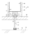
図1および図2は、本発明の一実施形態に係る間仕切り壁支持部材2を用いた二重床構造を示している。図1および図2に示す二重床構造は、建物躯体52の床面54から所定高さの間隔を空けて二重床用の床材30を設置した後、床材30の上面に間仕切り壁35を立設してなる、いわゆる床先行工法により構築されるものであり、集合住宅等の建物に適用される。
1 and 2 show a double floor structure using a partition
図2と図6に示すように、床材30には、間仕切り壁支持部材2の後述の支持脚10を挿通させるための複数の開口部32が所定箇所に穿設されている。開口部32は例えば円形とされ、開口部32の径は、間仕切り壁支持部材2の支持脚10の径の最大部分と比較して、5%以上30%未満大きくすることが好ましい。開口部32の径を、支持脚10の径の最大部分よりも5%以上大きくすることで、支持脚10を開口部32へ容易に挿通させることができ、施工性が向上する。開口部32の径を、支持脚10の径の最大部分よりも30%以上大きくすると、開口部32へ挿通させた支持脚10の接地位置が不安定となってしまう。
As shown in FIG. 2 and FIG. 6, a plurality of
床材30は、複数の支持脚42によって、構造躯体52の床面54から所定の間隔を空けた高さに支持されている。支持脚42は、隣接する床材30間に跨って床材30の下面に例えばビスにより固定された固定板48と、固定板48の中央部を上下方向に貫通する図示しない貫通穴に取り付けられたナット46と、ナット46に螺合されたボルト44と、ボルト44の下端部に取り付けられた緩衝部材50とを有する。
The
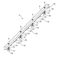
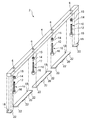
間仕切り壁支持部材2は、間仕切り壁35の下端を支持するための部材であり、図2に示すように、間仕切り壁35の下端部に沿って伸びる長尺の基材4と、基材4から建物躯体52の床面54まで伸びる支持脚10と、支持脚10と干渉しないようにして基材4と床材30との間に介在する防振部材18とを備えている。
The partition
図1および図4に示すように、基材4には、上下方向に貫通する複数の貫通穴6が、基材4の長手方向に所定の間隔を空けて形成されている。基材4の材料としては、例えば、建材として一般的に使用される合板材料、または単板積層材が用いられるが、その他の木質材料、または合成樹脂をベースとした木材代替材料を用いることもできる。基材4の断面形状は、例えば長方形とされるが、これに限定されず、例えば台形としてもよい。
As shown in FIGS. 1 and 4, a plurality of through
支持脚10は、基材4の長手方向に所定の間隔を空けて複数設けられ、各支持脚10の上端部が基材4に取り付けられている。隣接する支持脚10間の間隔は、特に限定されないが、例えば300mm以上600mm以下に設定される。
A plurality of
支持脚10は、基材4の貫通穴6に嵌め込まれたナット14と、ナット14に螺合されたボルト12と、ボルト12の下端部に取り付けられた緩衝部材16とを有する。
The
ナット14の外周面には、フランジ15が径方向外側へ張り出して形成されている。ナット14の外径は、基材4の貫通穴6の径よりも僅かに大きく、ナット14は、基材4の下側から貫通穴6へ圧入されることで、貫通穴6に嵌め込まれる。ナット14は、フランジ15よりも上側の部分のみが貫通穴6に嵌め込まれ、フランジ15よりも下側の部分は、基材4の下側に露出した状態となる。ナット14としては、例えば鋼製または樹脂製のものが用いられるが、ナット14の素材は特に限定されるものではない。
A
ボルト12は、ナット14に対して下側からねじ込まれることで、ナット14に組み付けられる。ボルト12の上端面には、ボルト12を操作するための溝が形成されており、ボルト12の溝にドライバー等を係合させることで、ボルト12の回転操作が可能となっている。
The
緩衝部材16としては、ゴムまたは軟質の樹脂を用いることが好ましく、これにより、構造躯体52の床面54の不陸を吸収して、床面54上に支持脚10を安定して載置できる。
As the
このように構成された支持脚10は、基材4に取り付けられた状態において、基材4の下面より下方に突出し、該突出量、すなわち支持脚10の高さが調整可能となっている。具体的に、支持脚10の高さは、ボルト12を上側から回転操作することにより調整でき、より具体的には、ナット14に対して、ボルト12を下側へ螺進させることで支持脚10を長くすることができ、ボルト12を上側へ螺退させることで支持脚10を短くすることができる。
The
支持脚10は、床材30の開口部32に挿通されており、支持脚10の外周面と開口部32の周壁との間に空隙が確保されている。これにより、床材30の振動が、開口部32の周壁から支持脚10へ伝達しないようになっている。
The
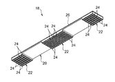
防振部材18は、基材4の下面に貼り付けられた薄肉の基部20と、基部20の下面より下方へ突出した突出部22とを備えている。防振部材18は、基部20において、支持脚10との干渉を避けるように基材4の下面に取り付けられ、突出部22において床材30の上面に当接している。
The
基部20は、図5に示すように、基部20の上面に形成された粘着剤層26を介して基材4の下面に貼り付けられる。なお、防振部材18の基材4への取付け前において、粘着剤層26は、図示しない離型紙等の被覆部材で被覆しておくことが好ましい。ただし、粘着剤層26は、必ずしも設ける必要はなく、防振部材18は、粘着剤または接着剤を基部20の上面に塗布して基材4に貼り付けてもよい。
As shown in FIG. 5, the
突出部22は、基材4の長手方向に間隔を空けて複数配置されている。突出部22の下面には複数の凸部24が形成されているが、必ずしも凸部24を設ける必要はない。複数の突出部22の下面は、互いに略同一面上に配置され、且つ、床材30の上面への載置面とされている。
A plurality of protruding
図4に示すように、防振部材18は、基材4の下面において隣接する一対の支持脚10により挟まれた部分に取り付けられる。なお、基材4の端部の下面には、適当な大きさにカットされた防振部材18が取り付けられる。
As shown in FIG. 4, the
防振部材18は軟質素材からなる。防振部材18の具体的な素材としては、例えばゴムまたは熱可塑性エラストマーが用いられる。防振部材18は、床衝撃音発生時の振動を十分に軽減するため、JIS K6253に準拠したAタイプ硬度を20以上70以下に調製することが好ましい。
The
防振部材18の素材としてゴムを用いる場合、防振部材18は、1種または2種以上のゴム配合組成物を混合または積層して架橋成型することで製造でき、防振部材18の素材として熱可塑性エラストマーを用いる場合、防振部材18は、1種または2種以上の熱可塑性エラストマー配合組成物を混合または積層して成型することで製造できる。
When rubber is used as the material of the
間仕切り壁35の構成は、特に限定されないが、図1と図2に示すように、本実施形態に係る間仕切り壁35は、間仕切り壁支持部材2の基材4の上面に固定されたスチールランナー36と、スチールランナー36の上に立設された複数のスタッド38と、スチールランナー36の幅方向においてスチールランナー36を挟んだ両側に設けられた複数の壁材40とを有する。
The configuration of the
スチールランナー36としては、例えばCチャンネルが用いられる。スチールランナー36は、上向きに開放した状態で間仕切り壁支持部材2の基材4の長手方向に沿って配置され、ビス等により基材4の上面に固定されている。ただし、スチールランナー36に代えて、鋼製系材料または木質系材料等からなるその他の長尺部材を用いてもよい。
As the
スタッド38としては、例えばロ字形の鋼材が用いられる。スタッド38は、スチールランナー36の長手方向に所定の間隔を空けて複数配置され、各スタッド38の下端部が、ビス等によりスチールランナー36に固定されている。ただし、スタッド38としては、鋼製系材料または木質系材料等からなるその他の長尺部材を用いてもよい。
As the
壁材40としては、例えば、石膏ボードまたは化粧合板等が用いられる。壁材40は、複数のスタッド38に跨って取り付けられ、ビス等によりスタッド38およびスチールランナー36に固定されている。なお、壁材40の表面には、図示しない壁紙等の化粧材が取り付けられる。
As the
以上のように構成された二重床構造では、床衝撃音が発生したとき、床材30の振動は、床材30から間仕切り壁支持部材2の支持脚10へ直接伝達されない。また、間仕切り壁支持部材2の基材4と床材30との間には防振部材18が介在するため、床材30から基材4への振動の伝達は大きく軽減される。したがって、床衝撃音発生時の振動は、床材30から間仕切り壁支持部材2へ極めて伝達され難いため、床材30から間仕切り壁35への振動の伝達を十分に軽減でき、間仕切り壁35を介して階下に伝わる床衝撃音レベルを大きく低減できる。また、同様に、間仕切り壁35から床材30への振動の伝達も十分に軽減できる。
In the double floor structure configured as described above, when floor impact sound is generated, the vibration of the
次に、本発明に係る二重床構造の施工方法の具体例を説明する。 Next, the specific example of the construction method of the double floor structure concerning this invention is demonstrated.
図6および図7に示すように、先ず、二重床用の床材30を支持する複数の支持脚42を、構造躯体52の床面54上の所定位置に配置し、これらの支持脚42に床材30を取り付ける。続いて、支持脚42のボルト44を回転操作することで支持脚42の長さ調整を行い、床材30の高さを所定高さに調整する。これにより、床材30が、建物躯体52の床面54から所定高さの間隔を空けて設置される。
As shown in FIG. 6 and FIG. 7, first, a plurality of
次に、間仕切り壁35を設置する位置に応じて、床材30の所定の位置に、間仕切り壁支持部材2の支持脚10を挿通させるための開口部32を穿設する。このとき、開口部32は、床材30の任意の位置に穿設して、間仕切り壁35を任意の位置に設置できるため、設計の自由度が高められている。
Next, according to the position where the
続いて、床材30の上側から複数の間仕切り壁支持部材2を設置する。各間仕切り壁支持部材2を設置する際は、間仕切り壁支持部材2の支持脚10を床材30の開口部32へ上側から挿通させながら、間仕切り壁支持部材2の基材4を床材30の上面に載置する。これにより、基材4と床材30との間に防振部材18が介装される。このとき、基材4は、床材30上に載置するだけで所定の高さに設置されるため、基材4のレベル調整作業を行う必要がなく、施工の簡略化を図ることができる。
Subsequently, a plurality of partition
床材30の上面に基材4を載置した後、図8に示すように、支持脚10のボルト12を回転操作することで、支持脚10を下方へ伸長させ、支持脚10の下端を構造躯体52の床面54に当接させる。このように支持脚10の長さ調整を行った後、支持脚10の長さを一定に維持するため、ボルト12とナット14とを接着剤で固定する。その後、ビス等により基材4を床材30に固定する。
After the
このように間仕切り壁支持部材2を設置した後、床材30の上面に、基材4に沿って間仕切り壁35を立設する。具体的に、図1および図2に示すように、基材4の上面にスチールランナー36を固定し、スチールランナー36の上に、複数のスタッド38を所定の間隔を空けて配置してスチールランナー36に固定し、スタッド38およびスチールランナー36に、スチールランナー36の幅方向両側から壁材40を固定する。最後に、壁材40の表面に図示しない化粧材を貼り付けることで、間仕切り壁35が設置される。
After installing the partition
以上、上述の実施形態を挙げて本発明を説明したが、本発明は上述の実施形態に限定されるものではない。 While the present invention has been described with reference to the above-described embodiments, the present invention is not limited to the above-described embodiments.
2:間仕切り壁支持部材、
4:基材、
10:支持脚、
18:防振部材、
20:防振部材の基部、
22:防振部材の突出部、
30:床材、
52:構造躯体、
54:構造躯体の床面。
2: Partition wall support member,
4: Substrate,
10: support legs,
18: Anti-vibration member,
20: the base of the vibration isolator,
22: Protruding part of the vibration isolating member,
30: flooring,
52: Structural enclosure,
54: Floor surface of the structural frame.
Claims (4)
二重床用の床材を建物躯体の床面から所定高さの間隔を空けて設置する工程と、
上記床材の設置後、上記の用意された間仕切り壁支持部材を、上記基材と上記床材との間に上記防振部材が介在するように、上記床材の上面に載置する工程と、
上記間仕切り壁支持部材の載置後、上記床材の上面に、上記間仕切り壁支持部材の基材に沿って間仕切り壁を立設する工程とを備えたことを特徴とする二重床構造の施工方法。 A long base, a support leg protruding downward from the lower surface of the base, a thin base made of a soft material, a plurality of protrusions protruding downward from the lower surface of the base, and a lower surface of the protrusion An anti-vibration member having a plurality of formed protrusions, and the plurality of protrusions are spaced apart in the longitudinal direction of the substrate so as to avoid interference between the anti-vibration member and the support legs. Preparing a partition wall support member in which the upper surface of the base is affixed to the lower surface of the base material so as to be disposed;
Installing a floor for double floors at a predetermined height from the floor of the building frame;
Placing the prepared partition wall support member on the upper surface of the floor material so that the vibration isolating member is interposed between the base material and the floor material after the floor material is installed; ,
After the partition wall support member is placed, a construction of a double floor structure comprising a step of standing a partition wall along the base material of the partition wall support member on the upper surface of the floor material Method.
上記間仕切り壁の下端部に沿って配置される長尺の基材と、
該基材の下面より下方に突出し、且つ、該突出量が調整可能な支持脚と、
軟質素材からなる防振部材と、を備え、
上記防振部材は、薄肉の基部と、該基部の下面より下方へ突出した複数の突出部と、該突出部の下面に形成された複数の凸部とを有し、
上記基材の下面に、上記防振部材と上記支持脚との干渉を避けるように且つ上記複数の突出部が上記基材の長手方向に間隔を空けて配置されるように上記基部の上面が貼り付けられていることを特徴とする間仕切り壁支持部材。 In the building where the partition wall is erected on the upper surface of the floor material constituting the double floor, the partition wall support member that supports the lower end of the partition wall,
A long base material disposed along the lower end of the partition wall;
A support leg that protrudes downward from the lower surface of the base material, and the protrusion amount is adjustable;
An anti-vibration member made of a soft material ,
The vibration isolator has a thin base, a plurality of protrusions protruding downward from the lower surface of the base, and a plurality of protrusions formed on the lower surface of the protrusion,
The upper surface of the base portion is disposed on the lower surface of the base material so as to avoid interference between the vibration isolating member and the support legs, and the plurality of protrusions are arranged at intervals in the longitudinal direction of the base material. A partition wall support member, wherein the partition wall support member is attached .
該床材の上面に立設された間仕切り壁と、
該間仕切り壁の下端を支持する間仕切り壁支持部材とを備えた二重床構造であって、
上記間仕切り壁支持部材は、上記間仕切り壁の下端部に沿って伸びる長尺の基材と、該基材から上記建物躯体の床面まで伸びる支持脚と、軟質素材からなる防振部材と、を備え、
上記防振部材は、薄肉の基部と、該基部の下面より下方へ突出した複数の突出部と、該突出部の下面に形成された複数の凸部とを有し、
上記基材の下面に、上記防振部材と上記支持脚との干渉を避けるように且つ上記複数の突出部が上記基材の長手方向に間隔を空けて配置されるように上記基部の上面が貼り付けられており、
上記床材の上面に、上記突出部の下面が載置されていることを特徴とする二重床構造。 Floor materials for double floors arranged at a predetermined height from the floor of the building frame;
A partition wall erected on the upper surface of the flooring;
A double floor structure comprising a partition wall support member for supporting the lower end of the partition wall,
The partition wall support member includes a long base extending along the lower end of the partition wall, a support leg extending from the base to the floor of the building frame, and a vibration isolating member made of a soft material. Prepared,
The vibration isolator has a thin base, a plurality of protrusions protruding downward from the lower surface of the base, and a plurality of protrusions formed on the lower surface of the protrusion,
The upper surface of the base portion is disposed on the lower surface of the base material so as to avoid interference between the vibration isolating member and the support legs, and the plurality of protrusions are arranged at intervals in the longitudinal direction of the base material. Pasted,
The double floor structure, wherein the lower surface of the protruding portion is placed on the upper surface of the floor material .
Priority Applications (1)
| Application Number | Priority Date | Filing Date | Title |
|---|---|---|---|
| JP2007025315A JP4384186B2 (en) | 2007-02-05 | 2007-02-05 | Construction method of double floor structure, partition wall support member and double floor structure |
Applications Claiming Priority (1)
| Application Number | Priority Date | Filing Date | Title |
|---|---|---|---|
| JP2007025315A JP4384186B2 (en) | 2007-02-05 | 2007-02-05 | Construction method of double floor structure, partition wall support member and double floor structure |
Publications (2)
| Publication Number | Publication Date |
|---|---|
| JP2008190204A JP2008190204A (en) | 2008-08-21 |
| JP4384186B2 true JP4384186B2 (en) | 2009-12-16 |
Family
ID=39750545
Family Applications (1)
| Application Number | Title | Priority Date | Filing Date |
|---|---|---|---|
| JP2007025315A Active JP4384186B2 (en) | 2007-02-05 | 2007-02-05 | Construction method of double floor structure, partition wall support member and double floor structure |
Country Status (1)
| Country | Link |
|---|---|
| JP (1) | JP4384186B2 (en) |
Families Citing this family (1)
| Publication number | Priority date | Publication date | Assignee | Title |
|---|---|---|---|---|
| US8683749B2 (en) * | 2011-03-25 | 2014-04-01 | Baltimore Aircoil Company, Inc. | Cooling tower entry door structure |
-
2007
- 2007-02-05 JP JP2007025315A patent/JP4384186B2/en active Active
Also Published As
| Publication number | Publication date |
|---|---|
| JP2008190204A (en) | 2008-08-21 |
Similar Documents
| Publication | Publication Date | Title |
|---|---|---|
| EP2551422A2 (en) | Sound-insulating and vibration-isolating rubber pad and method for installing a sound-insulating and vibration-isolating floor using same | |
| JP4384186B2 (en) | Construction method of double floor structure, partition wall support member and double floor structure | |
| JP2011157728A (en) | Damper and wood construction using the same | |
| KR101400768B1 (en) | Anti-vibration support struture | |
| JP6428851B1 (en) | Anti-vibration structure and sound insulation floor structure for horizontal members | |
| JP5878766B2 (en) | Sound insulation ceiling structure | |
| JP2005290708A (en) | Double floor structure and floor construction method | |
| JP2009133071A (en) | Floor structure of wooden house | |
| JP2009127248A (en) | Double floor | |
| JP4090853B2 (en) | Floor construction, joist pad and construction method for floor construction | |
| JP3850278B2 (en) | Reinforcement structure for the edge of the wall of the level adjustment floor panel, and reinforcement method for the edge of the wall | |
| JP5737895B2 (en) | Partition structure | |
| JP5670675B2 (en) | Sound insulation dry double floor and its construction method | |
| JP2010174586A (en) | Floor structure and floor support | |
| JP2016148217A (en) | Double floor | |
| JP2009293284A (en) | Partition structure | |
| JP2001295451A (en) | Double floor structure and method of constructing partition or heavy material placed object | |
| JP2000027333A (en) | Interior finishing device of structure | |
| JP6480783B2 (en) | Sound insulation floor structure | |
| JP2005226329A (en) | Floor panel structure | |
| JP2017166172A (en) | Floor support, double floor structure and double floor structure construction method | |
| JP4627322B2 (en) | Double floor structure | |
| JP2007231689A (en) | Sound insulating floor structure using impact damper | |
| JP2009091735A (en) | Sub-floor structure | |
| JP2013079529A (en) | Joist unit for low floor and joist bracket used therein |
Legal Events
| Date | Code | Title | Description |
|---|---|---|---|
| A977 | Report on retrieval |
Free format text: JAPANESE INTERMEDIATE CODE: A971007 Effective date: 20090527 |
|
| A131 | Notification of reasons for refusal |
Free format text: JAPANESE INTERMEDIATE CODE: A131 Effective date: 20090602 |
|
| A521 | Written amendment |
Free format text: JAPANESE INTERMEDIATE CODE: A523 Effective date: 20090729 |
|
| TRDD | Decision of grant or rejection written | ||
| A01 | Written decision to grant a patent or to grant a registration (utility model) |
Free format text: JAPANESE INTERMEDIATE CODE: A01 Effective date: 20090825 |
|
| A01 | Written decision to grant a patent or to grant a registration (utility model) |
Free format text: JAPANESE INTERMEDIATE CODE: A01 |
|
| A61 | First payment of annual fees (during grant procedure) |
Free format text: JAPANESE INTERMEDIATE CODE: A61 Effective date: 20090924 |
|
| FPAY | Renewal fee payment (event date is renewal date of database) |
Free format text: PAYMENT UNTIL: 20121002 Year of fee payment: 3 |
|
| R150 | Certificate of patent or registration of utility model |
Ref document number: 4384186 Country of ref document: JP Free format text: JAPANESE INTERMEDIATE CODE: R150 Free format text: JAPANESE INTERMEDIATE CODE: R150 |
|
| FPAY | Renewal fee payment (event date is renewal date of database) |
Free format text: PAYMENT UNTIL: 20151002 Year of fee payment: 6 |
|
| R250 | Receipt of annual fees |
Free format text: JAPANESE INTERMEDIATE CODE: R250 |
|
| R250 | Receipt of annual fees |
Free format text: JAPANESE INTERMEDIATE CODE: R250 |
|
| R250 | Receipt of annual fees |
Free format text: JAPANESE INTERMEDIATE CODE: R250 |
|
| R250 | Receipt of annual fees |
Free format text: JAPANESE INTERMEDIATE CODE: R250 |