JP4383650B2 - Device for controlling or adjusting electromechanical brakes - Google Patents
Device for controlling or adjusting electromechanical brakes Download PDFInfo
- Publication number
- JP4383650B2 JP4383650B2 JP2000502968A JP2000502968A JP4383650B2 JP 4383650 B2 JP4383650 B2 JP 4383650B2 JP 2000502968 A JP2000502968 A JP 2000502968A JP 2000502968 A JP2000502968 A JP 2000502968A JP 4383650 B2 JP4383650 B2 JP 4383650B2
- Authority
- JP
- Japan
- Prior art keywords
- actuator
- akt
- module
- friction surface
- signal
- Prior art date
- Legal status (The legal status is an assumption and is not a legal conclusion. Google has not performed a legal analysis and makes no representation as to the accuracy of the status listed.)
- Expired - Lifetime
Links
Images


Classifications
-
- F—MECHANICAL ENGINEERING; LIGHTING; HEATING; WEAPONS; BLASTING
- F16—ENGINEERING ELEMENTS AND UNITS; GENERAL MEASURES FOR PRODUCING AND MAINTAINING EFFECTIVE FUNCTIONING OF MACHINES OR INSTALLATIONS; THERMAL INSULATION IN GENERAL
- F16D—COUPLINGS FOR TRANSMITTING ROTATION; CLUTCHES; BRAKES
- F16D65/00—Parts or details
- F16D65/38—Slack adjusters
- F16D65/40—Slack adjusters mechanical
- F16D65/52—Slack adjusters mechanical self-acting in one direction for adjusting excessive play
- F16D65/56—Slack adjusters mechanical self-acting in one direction for adjusting excessive play with screw-thread and nut
-
- B—PERFORMING OPERATIONS; TRANSPORTING
- B60—VEHICLES IN GENERAL
- B60T—VEHICLE BRAKE CONTROL SYSTEMS OR PARTS THEREOF; BRAKE CONTROL SYSTEMS OR PARTS THEREOF, IN GENERAL; ARRANGEMENT OF BRAKING ELEMENTS ON VEHICLES IN GENERAL; PORTABLE DEVICES FOR PREVENTING UNWANTED MOVEMENT OF VEHICLES; VEHICLE MODIFICATIONS TO FACILITATE COOLING OF BRAKES
- B60T13/00—Transmitting braking action from initiating means to ultimate brake actuator with power assistance or drive; Brake systems incorporating such transmitting means, e.g. air-pressure brake systems
- B60T13/74—Transmitting braking action from initiating means to ultimate brake actuator with power assistance or drive; Brake systems incorporating such transmitting means, e.g. air-pressure brake systems with electrical assistance or drive
-
- F—MECHANICAL ENGINEERING; LIGHTING; HEATING; WEAPONS; BLASTING
- F16—ENGINEERING ELEMENTS AND UNITS; GENERAL MEASURES FOR PRODUCING AND MAINTAINING EFFECTIVE FUNCTIONING OF MACHINES OR INSTALLATIONS; THERMAL INSULATION IN GENERAL
- F16D—COUPLINGS FOR TRANSMITTING ROTATION; CLUTCHES; BRAKES
- F16D65/00—Parts or details
- F16D65/38—Slack adjusters
- F16D2065/386—Slack adjusters driven electrically
Description
本発明は、アクチュエータによって電気的に操作可能な第1の摩擦面と、第2の摩擦面とを備え、この両摩擦面の間に空隙が設けられ、更に、アクチュエータの位置とアクチュエータに供給される電流を直接的または間接的に検出する手段と、第2の摩擦面に対する第1の摩擦面の接触を検出し、接触信号を発生する装置とを備えている、ブレーキを制御または調整する方法と、電気的に操作可能なブレーキを制御または調整する装置に関する。
【0001】
このような方法と装置は例えばドイツ連邦共和国特許出願公開第1953669.5号公報によって知られている。この公報では、方法のために必要な接触信号を発生する2つの方法が提案されている。第1の方法では、アクチュエータトルクが一定のときにアクチュエータ速度が評価され、第2の方法では、接触信号を発生するための接触ピンが使用される。
【0002】
接触点を決定するための第1の方法の欠点は、定めて行われる初期化サイクルの間でのみ接触決定が可能である、すなわちブレーキを予め設定されたアクチュエータ目標値で制御しなければならないという点にある。このサイクルの間、アクチュエータの変化が評価される。運転者または上位の制御装置によるブレーキ操作時に、一定のトルクによる制御は不可能である。というのは、空隙をできるだけ迅速に零まで縮小しなければならず、ブレーキが通常運転では力制御モードで運転されるからである。しかし、力制御モードはブレーキのパワー制御をトルク制御モードではなく、回転数制御モードで行う。力コントローラがトルクコントローラに直接重ね合わされるときでも、空隙を一定のトルクで零まで小さくするために多大なコストがかかる。更に、アクチュエータのパワー制御装置は、ブレーキのトルク制御操作のための運転モードを有していなければならない。トルクコントローラの上位の回転数コントローラを備えた力制御または位置制御装置が使用され、この回転数コントローラが同様にパワー制御装置で実施されていると、ブレーキのパワー制御装置は、両運転モード、すなわち電流制御と回転数制御の間で切換えるためのスイッチを備えなければならない。しかし、このスイッチは付加的なコストを生じる。
【0003】
他の方法は、摩擦面に嵌め込まれた接触ピンの使用に基づいており、それによって付加的なハードウェア手段を必要とする。
【0004】
そこで、本発明の課題は、アクチュエータ特有のパラメータを用いて空隙を検出および調節することができる、制御または調整方法を提供することである。本発明の他の課題は、特別なブレーキ操作に関係なく作動し、更に自動車の走行中空隙の再調節を可能にする、空隙を検出し、再調節する制御または調整装置を提供することである。
【0005】
この課題は方法においては、接触を検出するために、アクチュエータ電流の変化とアクチュエータ位置の変化を評価することによって解決される。
【0006】
本発明思想を具体化するために、検出されたアクチュエータ電流に、アクチュエータトルクまたはアクチュエータ力が関連づけられる。
【0007】
その際好ましくは、接触を検出するために、アクチュエータ側の装置剛性が、アクチュエータ位置によるアクチュエータトルクまたはアクチュエータ力の微分として決定される。アクチュエータ側の装置剛性が閾値を上回ることあるいは下回ることを監視すると有利である。前述の装置剛性量の使用は前述の方法に対して次の利点がある。
a)装置剛性量は初期化相(すなわち、例えば車両をスタートさせた後で空隙を新たに調節する際)においておよびブレーキ操作中に、接触点を決定するためにブレーキング時に使用可能である。装置剛性量はすべてのブレーキング時に空隙を再調節するためにも適している。
b)装置剛性の評価は、電気動力装置の2つの運転モード、すなわち“回転数制御”と“トルク制御”の切換えを必要としない。なぜなら、励起信号が検出時に一定のトルクである必要がないからである。
【0008】
本発明による方法の他の有利な特徴は従属請求項5〜12から推察可能である。
【0009】
上述の方法を実施するための本発明による制御および調整装置は、
a)第1の制御モードと第2の制御モードの間で切換え可能なコントローラが設けられ、ブレーキ操作時に所望される力またはトルクの目標値と実際値を示す信号と、アクチュエータ目標位置を示す信号と、スイッチング変数と、第2の摩擦面に対する第1の摩擦面の接触を示す信号が入力量としてコントローラに供給され、コントローラが第1の操作量を発生し、
b)空隙案内兼監視モジュールが設けられ、空隙検出を可能にする制御変数と、アクチュエータに供給される電流とアクチュエータ位置に対応する信号とが、空隙案内兼監視モジュールに供給され、空隙案内兼監視モジュールがアクチュエータ目標位置を示す信号と、スイッチング変数と、第2の摩擦面に対する第1の摩擦面の接触を示す信号を供給し、かつ第2の操作量を発生し、
c)第1の操作量と第2の操作量が選択回路に供給され、この選択回路が第2のスイッチング変数に依存して、両操作量の一方を、電子的な制御回路(サーボ増幅器)に供給し、この制御回路の出力信号によってアクチュエータが制御されることを特徴とする。
【0010】
その際好ましくは、前述のコントローラの第1の制御モードがアクチュエータ位置制御に相当し、第2の制御モードがブレーキ力/ブレーキトルク制御または減速度制御に相当する。
【0011】
発明思想の他の実施形では、空隙案内兼監視モジュールが目標値発生器と接触点を検出するための装置からなり、制御変数が目標値発生器に入力量として供給され、アクチュエータに供給される電流とアクチュエータ位置に対応する信号が、接触点を検出する装置に入力量として供給され、目標値発生器がアクチュエータ目標位置を示す信号と、第1のスイッチング変数と、第2のスイッチング変数と、第2の操作量を発生し、接触点を検出する装置が、第2の摩擦面に対する第1の摩擦面の接触を示す信号を発生する。
【0012】
その際好ましくは、接触点を検出する装置が、信号をろ波し慣性力を相殺するための第1のモジュールと、この第1のモジュールの後に接続配置された、アクチュエータ側の装置剛性を決定するための第2のモジュールと、決定された装置剛性を閾値と比較するための第3のモジュールを備えている。信頼性チェックのための第4のモジュールが第1のモジュールと第2のモジュールと第3のモジュールに対して平行に接続配置され、アクチュエータ位置を示す信号あるいはアクチュエータ電圧またはアクチュエータ電流を示す信号が、第4のモジュールに入力量として供給され、第4のモジュールが第2のモジュールと第3のモジュールの機能の開始を可能にすると特に有利である。
【0013】
本発明の他の詳細、特徴および効果は、添付の図を参照した、実施の形態の次の説明から明らかになる。
【0014】
次の記載は原理を良好に理解するために電気的なスポット型ディスクブレーキに関する。しかし、この方法は変更しないで他の電気操作式ブレーキ(例えば電気操作式ドラムブレーキ)で使用可能である。
【0015】
この方法は、接触点を決定するために、少なくとも一方のブレーキパッドがディスクに接触しているかどうかについての2進情報を供給する接触信号K*が、接触点を検出するための装置で求められるという事実から出発している。接触点は、パッドが力を加えないでディスクに接触するアクチュエータ位置を示している。
【0016】
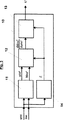
図1に示した制御装置は実質的に、コントローラ1と、空隙案内兼監視モジュール2と、選択回路3と、この選択回路3の後に接続配置されたサーボ増幅器(サーボブースター)4とからなっている。このサーボ増幅器の出力信号IAkt によって、参照符号6で示した電気機械式に操作可能なブレーキの略示したアクチュエータ5が制御される。アクチュエータは好ましくは位置測定装置7を備えている。アクチュエータ実際位置を示すこの位置測定装置の出力信号ψAkt,Messは一方ではサーボ増幅器4に、他方では位置信号処理回路8に供給される。
【0017】
コントローラ1は好ましくは切換え可能に形成され、従ってアクチュエータ位置制御を行う第1の制御モードあるいはブレーキ力制御、ブレーキトルク制御または締付け力制御を行う第2の制御モードで運転可能である。このコントローラの入力量は締付け力目標値Vsoll、締付け力実際値Vist 、アクチュエータ目標位置を示す信号ψsoll、スイッチング変数S1 および前述の接触信号K*である。この場合、出力量は選択回路3に供給される操作量CMD1である。減速希望目標値Vsollは上位レベル(例えばABSコントローラまたはASMSコントローラ)から供給される。一方、減速実際値Vist はコントローラフィードバック量を示す。アクチュエータ目標位置に対応する信号ψsollとスイッチング変数S1 は、空隙案内兼監視モジュール2から供給される。この空隙案内兼監視モジュールの入力量は空隙検出を開始するための制御変数STと、アクチュエータ5に供給される電流に対応するサーボ増幅器4の出力信号IAkt と、位置信号処理回路8の出力信号ψAkt である。空隙案内兼監視モジュール2の出力信号は選択回路3の挙動に影響を与える第2のスイッチング変数S2 と、第2の操作量CMD2と、少なくとも一方のブレーキパッドとブレーキディスクとの接触時に発生する接触信号K*である。
【0018】
特に図2から判るように、空隙案内兼監視モジュール2は2個の機能ユニット、すなわち目標値発生器9と、ブレーキパッドとブレーキディスクとの接触、すなわち接触点を検出するための装置10とからなっている。目標値発生器9の入力量は上位の(図示していない)機能ユニットから供給される上述の制御変数STである。この制御変数によって、上位レベルは空隙を決定、調節および再調節するための処理手順を開始することができる。目標値発生器9の出力は2つのスイッチング変数S1 ,S2 と操作量CMD2である。スイッチング変数S1 は位置制御と力またはトルク制御との間でコントローラ1を切換える。スイッチング変数S2 はコントローラ1の操作量CMD1または目標値発生器9の操作量CMD2を、サーボ増幅器4の入力に切換える。
【0019】
接触点を検出するための装置10の入力量は、アクチュエータ電流IAkt とアクチュエータ位置ψAkt である。この装置の出力は上述の接触信号K*である。この信号に基づいて、目標値発生器9は上記の問題を解決するためにコントローラ1のための制御戦略を起案する。
【0020】
目標値発生器9は3つの運転モードを有する。
1)このモードは、アクチュエータの位置信号の絶対位置が知られていないかまたは新たに決定しなければならないときに、空隙を決定するために用いられる。これは例えば、ブレーキパッドおよびまたはディスクを交換する場合あるいは車両を停止した後で空隙の新たな調節を必要とする場合である。このモードは制御変数STを介して動作開始される。目標値発生器9がこの運転モードにあると、スイッチング変数S2 が先ず最初に“1”にセットされる。それによって、空隙案内兼監視モジュール2の出力信号CMD2はブレーキ6のパワー制御装置(動作ユニット)に送られる。コントローラ1の操作量CMD1は作用しないままである。空隙調節の戦略の実現の際、操作量CMD2は一定のアクチュエータトルクを示さない。それどころか、操作量CMD2をアクチュエータトルクとアクチュエータ回転数から演算することが適切である。この場合例えば、一定のパワーPを予め設定することができる。これは、P=MAkt ・ωAkt となるようにCMD2を予め設定することによって可能である。ここで、MAkt はアクチュエータの電気的入力量によって決定可能である(多くの種類のアクチュエータの場合、MAkt はアクチュエータ電流IAkt に比例する)。
【0021】
位置信号ψAkt に基づいて、ブレーキが通風されると、すなわち空隙が存在すると、接触信号K*が観察される。“1”に切り換えると、少なくとも一方のパッドがブレーキディスクに接触し、目標値発生器9が次に説明するモード3)となる。すなわち空隙調節を行う。
【0022】
位置信号ψAkt に基づいて、既にブレーキが作用していることが判ると、S2 は“0”にセットされ、コントローラ1はS1 を“1”にセットすることによって位置制御モードに切換えられる。ブレーキ6は少しだけ戻り、空隙初期化のための上述の空隙検出の処理手順が新たに開始される。
2)ブレーキ操作時の空隙検出
ブレーキ操作中、空隙はいろいろな要因(例えば加熱によるパッド膨張、摩耗によるパッド磨損等)によって変化する。しかし、走行運転中、空隙を初期化することは望ましくない。というのは、このような初期化が常に、アクチュエータ信号に基づいて、(小さなブレーキトルクに関連して)一方の摩擦パートナーが他方の摩擦パートナーに当たる運動を含むからである。従って、運転者または上位のコントロール装置によって開始されたブレーキング中に空隙を再調節することが望ましい。そのために、目標値発生器9はブレーキングの開始前にモード2)に切換えられる。このモードでは、コントローラ1または上位のレベルは接触信号K*を観察する。“0”から“1”に切換える際に、絶対位置ψ0 は新たに初期化される。空隙を調節することが望ましいと(モード“3”)、空隙のための目標位置は実際の絶対位置によって演算される。
3)空隙調節
第3のモード、すなわち空隙調節は、モード“1”での空隙検出の後であるいはブレーキ操作の終了後、空隙を調節するために役立つ。そのために、目標値発生器9はコントローラ1をスイッチング変数S1 =1によって位置制御モードに切換える。目標値発生器9はスイッチング変数S2 =0によって、コントローラ1の出力信号CMD1をサーボ増幅器4の入力部に生じる。目標値発生器9の出力信号ψsollによって、空隙の位置目標値がコントローラ1に通知される。この位置目標値は絶対的な零位置ψ0 (接触信号K*による初期化または適応)と、予め決定された空隙ψLSとから演算される。それによって、位置目標値信号についてψsoll=ψ0 −ψLSが生じる。
【0023】
図3には、図2に関連して述べた、接触点を検出するための装置10の構造が示してある。この略図から判るように、装置は4つのモジュールからなっている。第1のモジュール11は信号調節、すなわち信号ろ波と装置内で発生する慣性力の相殺のために役立つ。入力量であるアクチュエータトルク(または比例する量、ここではアクチュエータ電流IAkt )とアクチュエータ角度ψAkt は先ず最初に、外乱を除去するために低域ろ波される。この場合好ましくは、ろ波された信号の時間的に一定の位相ずれを生じるいわゆるベッセルフィルタが使用される。この場合続いて、アクチュエータトルクに比例する入力信号IAkt から、アクチュエータトルクMAkt が演算される。慣性モーメントの相殺は、アクチュエータ5によって加速されなければならないブレーキの慣性モーメント全体からアクチュエータトルク信号MAkt を洗練化する。これは、操作力を加えるためのアクチュエータトルク(摩擦パートナーの締付け)と摩擦トルクだけがアクチュエータ側の装置精度を演算するために関連するので必要である。それによって、このモジュール1の出力量は、ろ波されたアクチュエータ位置信号ψAkt *と、ろ波され慣性モーメントだけ補正されたアクチュエータトルク信号MAkt *である。
【0024】
第2のモジュール12では、アクチュエータ側の装置剛性が確定または演算される。このアクチュエータ側の装置剛性とは商dMAkt */dψAkt *であると理解される。アクチュエータ角度によるアクチュエータトルクの微分によって、時間的な増大ではなく、(一方の摩擦パートナーが他方の摩擦パートナーに接触するときに発生するような、)位置に依存するアクチュエータトルクの増大が示される。これは、ブレーキ6の運動の時間的な変化が接触検出のために観察される信号dMAkt */dψAkt *に関連しないという利点がある。従って、“モータ側の装置剛性”の信号の変化は、ブレーキ6がかけられる速度に依存しない。
【0025】
第3のモジュール13は商dMAkt */dψAkt *を閾値SWと比較することによって接触信号K*を生じる。この信号は例えば、閾値を上回るときに値“1”にセットされ、閾値SWを下回るときに値“0”にセットされる。
【0026】
モジュール11〜13に対して平行に接続配置された第4のモジュール14には、アクチュエータ位置に対応する信号ψAkt が入力量として供給される。この第4のモジュールはいろいろな条件に基づいて、接触信号K*の発生がその瞬時の時点で適切であるかまたは確実であるかどうか、および接触信号K*自体が有効であるかどうかを検査する。接触信号K*が有効であると、スイッチング変数Z=1をセットすることによって第4のモジュール14はこの接触信号を装置10の出力に発生させ、第2のモジュール12内での商dMAkt */dψAkt *の演算を開始可能にする。第3の変数Zを用いることによって、例えばブレーキの停止時(dψAkt *=0)に不所望な出力信号または不所望な操作(例えば“0”による割算)が避けられる。
【0027】
既に述べたように、いろいろな妥当性条件をチェックするための入力として、図3ではアクチュエータ位置ψAkt が用いられる。しかし、信頼性チェックのために他の信号を用いることができる。
【図面の簡単な説明】
【図1】 本発明による方法を実施するための制御回路の構造を示す図である。
【図2】 図1の制御回路で使用される空隙案内兼監視モジュールの構造を示す図である。
【図3】 図1の制御回路で使用される、接触点を検出するための装置の構造を示す図である。The present invention includes a first friction surface that can be electrically operated by an actuator, and a second friction surface. A gap is provided between the friction surfaces, and the position of the actuator and the actuator are supplied to the actuator. A method of controlling or adjusting a brake, comprising: means for directly or indirectly detecting a current to be generated; and a device for detecting contact of the first friction surface with the second friction surface and generating a contact signal And an apparatus for controlling or adjusting an electrically operable brake.
[0001]
Such a method and apparatus are known, for example, from German Offenlegungsschrift 1953669.5. In this publication, two methods for generating a contact signal necessary for the method are proposed. In the first method, the actuator speed is evaluated when the actuator torque is constant, and in the second method, a contact pin for generating a contact signal is used.
[0002]
The disadvantage of the first method for determining the contact point is that contact determination is possible only during a defined initialization cycle, i.e. the brake must be controlled with a preset actuator target value. In the point. During this cycle, actuator changes are evaluated. At the time of brake operation by the driver or a higher-level control device, control with a constant torque is impossible. This is because the air gap must be reduced to zero as quickly as possible and the brake is operated in force control mode in normal operation. However, in the force control mode, the brake power control is performed not in the torque control mode but in the rotation speed control mode. Even when the force controller is directly superimposed on the torque controller, it is very expensive to reduce the air gap to zero with a constant torque. Furthermore, the actuator power control device must have an operation mode for the torque control operation of the brake. If a force control or position control device with a speed controller above the torque controller is used and this speed controller is also implemented in the power control device, the power control device for the brake will be in both operating modes, i.e. A switch must be provided to switch between current control and rotational speed control. However, this switch incurs additional costs.
[0003]
Another method is based on the use of contact pins fitted in the friction surface, thereby requiring additional hardware means.
[0004]
Therefore, an object of the present invention is to provide a control or adjustment method capable of detecting and adjusting a gap by using parameters specific to an actuator. Another object of the present invention is to provide a control or adjustment device for detecting and re-adjusting the air gap, which operates regardless of a special braking operation, and further allows readjustment of the air gap while the vehicle is running. .
[0005]
This problem is solved in the method by evaluating changes in actuator current and actuator position to detect contact.
[0006]
In order to embody the inventive idea, an actuator torque or an actuator force is associated with the detected actuator current.
[0007]
In this case, in order to detect contact, the device stiffness on the actuator side is preferably determined as a derivative of the actuator torque or actuator force with respect to the actuator position. It is advantageous to monitor the device stiffness on the actuator side above or below a threshold value. The use of the aforementioned device stiffness has the following advantages over the aforementioned method.
a) The amount of equipment stiffness can be used during braking to determine the contact point during the initialization phase (ie, for example, when the air gap is newly adjusted after starting the vehicle) and during braking. The device stiffness is also suitable for readjusting the air gap during all braking.
b) Evaluation of device stiffness does not require switching between two operating modes of the electric power unit, namely “rotational speed control” and “torque control”. This is because the excitation signal need not have a constant torque at the time of detection.
[0008]
Other advantageous features of the method according to the invention can be inferred from the dependent claims 5-12.
[0009]
A control and adjustment device according to the invention for carrying out the above method comprises:
a) A controller capable of switching between the first control mode and the second control mode is provided, and a signal indicating a target value and an actual value of a desired force or torque during a brake operation, and a signal indicating an actuator target position And a signal indicating the switching variable and the contact of the first friction surface with the second friction surface is supplied to the controller as an input amount, and the controller generates the first operation amount,
b) A gap guide / monitoring module is provided, and a control variable enabling gap detection, a current supplied to the actuator, and a signal corresponding to the actuator position are supplied to the gap guide / monitor module, and the gap guide / monitor is supplied. The module provides a signal indicating the actuator target position, a switching variable, and a signal indicating the contact of the first friction surface with the second friction surface, and generates a second manipulated variable;
c) The first manipulated variable and the second manipulated variable are supplied to the selection circuit, and the select circuit depends on the second switching variable, and one of the manipulated variables is converted into an electronic control circuit (servo amplifier). The actuator is controlled by the output signal of the control circuit.
[0010]
Preferably, the first control mode of the controller described above corresponds to actuator position control, and the second control mode corresponds to brake force / brake torque control or deceleration control.
[0011]
In another embodiment of the inventive idea, the gap guide and monitoring module comprises a target value generator and a device for detecting a contact point, and the control variable is supplied to the target value generator as an input quantity and supplied to the actuator. A signal corresponding to the current and the actuator position is supplied as an input quantity to the device for detecting the contact point, a signal indicating that the target value generator indicates the actuator target position, a first switching variable, a second switching variable, A device that generates a second manipulated variable and detects a contact point generates a signal indicating contact of the first friction surface with the second friction surface.
[0012]
In this case, it is preferable that the device for detecting the contact point determines the stiffness of the actuator on the side of the actuator connected to the first module for filtering the signal and canceling the inertial force, and connected after the first module. And a third module for comparing the determined device stiffness with a threshold. A fourth module for reliability check is arranged in parallel to the first module, the second module, and the third module, and a signal indicating an actuator position or a signal indicating an actuator voltage or an actuator current is provided. It is particularly advantageous if the fourth module is supplied as an input quantity and allows the fourth module to initiate the functions of the second module and the third module.
[0013]
Other details, features and advantages of the present invention will become apparent from the following description of embodiments with reference to the accompanying drawings.
[0014]
The following description relates to an electric spot type disc brake for better understanding of the principle. However, this method can be used with other electrically operated brakes (eg, electrically operated drum brakes) without modification.
[0015]
In this method, in order to determine the contact point, a contact signal K * that provides binary information as to whether at least one brake pad is in contact with the disc is determined by a device for detecting the contact point. It starts from the fact that. The contact point indicates the actuator position where the pad contacts the disk without applying force.
[0016]
The control device shown in FIG. 1 substantially comprises a
[0017]
The
[0018]
As can be seen in particular from FIG. 2, the air gap guide and
[0019]
The input quantity of the
[0020]
The
1) This mode is used to determine the air gap when the absolute position of the actuator position signal is not known or must be newly determined. This is the case, for example, when changing brake pads and / or discs or when a new adjustment of the air gap is required after stopping the vehicle. In this mode, the operation is started via the control variable ST. When the
[0021]
Position signal ψ Akt Based on the above, when the brake is ventilated, that is, when there is a gap, the contact signal K * is observed. When switched to “1”, at least one of the pads comes into contact with the brake disc, and the
[0022]
Position signal ψ Akt Based on the above, if it is found that the brake is already working, S 2 Is set to “0” and
2) Air gap detection during brake operation During brake operation, the air gap changes due to various factors (for example, pad expansion due to heating, pad wear due to wear, etc.). However, it is not desirable to initialize the air gap during running operation. This is because such initialization always involves the movement of one friction partner against the other friction partner (relative to the small brake torque) based on the actuator signal. Therefore, it is desirable to readjust the air gap during braking initiated by the driver or superordinate control device. For this purpose, the
3) Air gap adjustment The third mode, i.e. air gap adjustment, serves to adjust the air gap after air gap detection in mode "1" or after the end of the braking operation. For this purpose, the
[0023]
FIG. 3 shows the structure of the
[0024]
In the
[0025]
The
[0026]
The
[0027]
As already mentioned, in FIG. 3 the actuator position ψ Akt is used as an input for checking various validity conditions. Is used. However, other signals can be used for reliability checking.
[Brief description of the drawings]
FIG. 1 shows the structure of a control circuit for carrying out the method according to the invention.
FIG. 2 is a diagram showing a structure of a gap guide and monitoring module used in the control circuit of FIG. 1;
FIG. 3 is a diagram showing a structure of a device for detecting a contact point used in the control circuit of FIG. 1;
Claims (15)
接触を検出するために、アクチュエータ側の装置剛性が、アクチュエータ位置(ψ Akt )によるアクチュエータトルク(M Akt )またはアクチュエータ力(F Akt )の微分として決定または監視されることを特徴とする方法。A first friction surface and a second friction surface that can be electrically operated by the actuator are provided, and a gap is provided between the two friction surfaces. Further, the position of the actuator and the current supplied to the actuator can be directly means for or indirectly detected, by detecting a contact of the first friction surface against the second friction surface, and a device for generating a contact signal, a method of controlling or adjusting the brakes, In order to detect contact, the change in actuator current (I Akt ) and the change in actuator position (ψ Akt ) are evaluated, and the detected actuator current (I Akt ) is converted into actuator torque (M Akt ) or actuator force. In the method in which (F Akt ) is related ,
A method, characterized in that the device stiffness on the actuator side is determined or monitored as a derivative of the actuator torque (M Akt ) or actuator force (F Akt ) with respect to the actuator position (ψ Akt ) in order to detect contact .
a)第1の制御モードと第2の制御モードの間で切換え可能なコントローラ(1)が設けられ、ブレーキ操作時に所望される力またはトルクの目標値(Vsoll )と実際値(Vist )を示す信号と、アクチュエータ目標位置(ψsoll )を示す信号と、スイッチング変数(S1 )と、第2の摩擦面に対する第1の摩擦面の接触を示す信号(K*)が入力量としてコントローラに供給され、コントローラが第1の操作量(CMD1 ) を発生し、
b)空隙案内兼監視モジュール(2)が設けられ、空隙検出を可能にする制御変数(ST)と、アクチュエータ(5)に供給される電流(IAkt )とアクチュエータ位置(ψAkt )に対応する信号とが、空隙案内兼監視モジュールに供給され、空隙案内兼監視モジュールがアクチュエータ目標位置(ψsoll )を示す信号と、スイッチング変数(S1 )と、第2の摩擦面に対する第1の摩擦面の接触を示す信号(K*)を供給し、かつ第2の操作量(CMD2 )を発生し、
c)第1の操作量(CMD1 ) と第2の操作量(CMD2 )が選択回路に供給され、この選択回路が第2のスイッチング変数(S2 )に依存して、両操作量(CMD1 ,CMD2 )の一方を、電子的な制御回路(サーボ増幅器4)に供給し、この制御回路の出力信号(IAkt )によってアクチュエータ(5)が制御されることを特徴とする装置。A first friction surface and a second friction surface that can be electrically operated by the actuator are provided, and a gap is provided between the two friction surfaces. Further, the position of the actuator and the current supplied to the actuator can be directly or a means for indirectly detecting the first detects the contact of the friction surface against the second friction surface, and a device for generating a contact signal, to one of the claims 1-10 In a device for controlling or adjusting a brake in the manner described,
a) A controller (1) that can be switched between the first control mode and the second control mode is provided, and a desired value (V soll ) and an actual value (V ist ) of the desired force or torque during braking operation. , A signal indicating the actuator target position (ψ soll ), a switching variable (S 1 ), and a signal (K *) indicating the contact of the first friction surface with the second friction surface are input to the controller. And the controller generates the first manipulated variable (CMD 1 )
b) A gap guide and monitoring module (2) is provided, corresponding to the control variable (ST) enabling gap detection, the current (I Akt ) supplied to the actuator (5) and the actuator position (ψ Akt ). The signal is supplied to the air gap guide and monitoring module, where the air gap guide and monitoring module indicates the actuator target position (ψ soll ), the switching variable (S 1 ), and the first friction surface relative to the second friction surface. Supply a signal (K *) indicating the contact of, and generate a second manipulated variable (CMD 2 ),
c) The first manipulated variable (CMD 1 ) and the second manipulated variable (CMD 2 ) are supplied to the selection circuit, which depends on the second switching variable (S 2 ), One of CMD 1 and CMD 2 ) is supplied to an electronic control circuit (servo amplifier 4), and the actuator (5) is controlled by an output signal ( IAkt ) of this control circuit.
Applications Claiming Priority (3)
| Application Number | Priority Date | Filing Date | Title |
|---|---|---|---|
| DE19730094A DE19730094A1 (en) | 1997-07-14 | 1997-07-14 | System for controlling or regulating an electromechanical brake |
| DE19730094.4 | 1997-07-14 | ||
| PCT/EP1998/004307 WO1999003714A1 (en) | 1997-07-14 | 1998-07-10 | System for controlling or regulating an electromechanical brake |
Publications (2)
| Publication Number | Publication Date |
|---|---|
| JP2001510119A JP2001510119A (en) | 2001-07-31 |
| JP4383650B2 true JP4383650B2 (en) | 2009-12-16 |
Family
ID=7835641
Family Applications (1)
| Application Number | Title | Priority Date | Filing Date |
|---|---|---|---|
| JP2000502968A Expired - Lifetime JP4383650B2 (en) | 1997-07-14 | 1998-07-10 | Device for controlling or adjusting electromechanical brakes |
Country Status (5)
| Country | Link |
|---|---|
| US (2) | US6536562B1 (en) |
| EP (1) | EP0994797B1 (en) |
| JP (1) | JP4383650B2 (en) |
| DE (2) | DE19730094A1 (en) |
| WO (1) | WO1999003714A1 (en) |
Families Citing this family (61)
| Publication number | Priority date | Publication date | Assignee | Title |
|---|---|---|---|---|
| DE19947903B4 (en) * | 1999-02-09 | 2014-04-03 | Continental Teves Ag & Co. Ohg | Device for controlling or regulating a friction brake |
| DE10005869B4 (en) * | 1999-08-25 | 2009-11-05 | Continental Teves Ag & Co. Ohg | Method and control system for applying defined actuating forces |
| US6969126B2 (en) * | 2000-02-28 | 2005-11-29 | Hitachi, Ltd. | Braking apparatus and method of controlling the same |
| WO2001068428A1 (en) * | 2000-03-15 | 2001-09-20 | Continental Teves Ag & Co. Ohg | Method and control system for applying defined tensile forces |
| JP4033281B2 (en) | 2000-09-06 | 2008-01-16 | 日産自動車株式会社 | Braking device |
| JP4488160B2 (en) * | 2001-04-26 | 2010-06-23 | クノル−ブレムゼ ジステーメ フューア ヌッツファールツォイゲ ゲゼルシャフト ミット ベシュレンクテル ハフツング | Disc brake with electrically driven post-wear adjustment device |
| US6932438B2 (en) | 2001-07-31 | 2005-08-23 | Continental Teves Ag & Co. Ohg | Method for establishing the relationship between actuator position and actuator tensioning force |
| DE10205013A1 (en) * | 2001-07-31 | 2003-02-20 | Continental Teves Ag & Co Ohg | Method for determining relationship between actuator position and actuator tensioning force for electromechanical brake actuator |
| DE10152423C2 (en) | 2001-10-24 | 2003-08-21 | Lucas Automotive Gmbh | disc brake |
| ATE316025T1 (en) | 2001-11-23 | 2006-02-15 | Lucas Automotive Gmbh | OPERATION OF A VEHICLE BRAKE SYSTEM DEPENDENT ON BRAKE SURFACE TEMPERATURES |
| DE10228115B4 (en) * | 2002-06-24 | 2004-05-13 | Lucas Automotive Gmbh | Electrically actuated vehicle brake and method for controlling an electrically actuated vehicle brake |
| JP2003194119A (en) | 2001-12-28 | 2003-07-09 | Nissan Motor Co Ltd | Electric braking device |
| EP1485282B1 (en) | 2002-03-21 | 2006-05-03 | Lucas Automotive GmbH | Electrically actuatable vehicle brake and method for controlling an electrically actuatable vehicle brake |
| DE10214669B4 (en) * | 2002-04-03 | 2014-01-23 | Knorr-Bremse Systeme für Schienenfahrzeuge GmbH | Method and device for controlling an electrically operated wear adjustment device |
| DE10261969B4 (en) * | 2002-06-24 | 2011-01-05 | Lucas Automotive Gmbh | Electrically actuated vehicle brake and method for controlling an electrically actuated vehicle brake |
| FR2841311B1 (en) * | 2002-06-25 | 2004-12-24 | Renault Sa | DEVICE AND METHOD FOR DETERMINING THE CONDITION OF WEAR OF A BRAKING SYSTEM EQUIPPED WITH A MOTOR VEHICLE WHEEL |
| DE10302515B4 (en) * | 2003-01-23 | 2014-09-25 | Robert Bosch Gmbh | Device and method for force and / or position control of an electrical brake system of a motor vehicle |
| DE10322451A1 (en) * | 2003-05-19 | 2004-12-09 | Continental Teves Ag & Co. Ohg | Process for optimizing the friction coefficient of brake linings of a friction brake |
| EP1649186B1 (en) * | 2003-07-31 | 2020-01-22 | Freni Brembo S.p.A. | Method and apparatus for controlling a braking device in a vehicle and braking device |
| US7448701B2 (en) * | 2003-09-26 | 2008-11-11 | Haldex Brake Products Ab | System for control of brake actuator based at least in part upon tire/road friction force |
| US7314257B2 (en) * | 2003-09-26 | 2008-01-01 | Haldex Brake Products Ab | Tire slip model |
| US7129658B2 (en) * | 2003-10-15 | 2006-10-31 | Honeywell International Inc. | Electro-mechanical actuator braking apparatus and method using motor commutation sensor output to derive piston displacement |
| GB0324243D0 (en) * | 2003-10-16 | 2003-11-19 | Meritor Heavy Vehicle Braking | A control system and method for a disc brake |
| FR2862281B1 (en) * | 2003-11-19 | 2007-03-16 | Messier Bugatti | METHOD FOR ACTUATING AN AIRCRAFT BRAKE EQUIPPED WITH AT LEAST ONE ELECTROMECHANICAL ACTUATOR |
| FR2863994B1 (en) * | 2003-12-17 | 2006-03-17 | Bosch Gmbh Robert | CHECKING THE TIGHTENING OF AN AUTOMATIC PARKING BRAKE FOR A MOTOR VEHICLE |
| US6959969B2 (en) * | 2004-03-05 | 2005-11-01 | Delphi Technologies, Inc. | System and method for controlling a brake |
| US20050216160A1 (en) * | 2004-03-23 | 2005-09-29 | Delphi Technologies Inc. | Method for detecting electric-mechanical-brake pad drag and/or calculating actuator efficiency |
| DE102005011267A1 (en) * | 2004-04-17 | 2006-03-30 | Continental Teves Ag & Co. Ohg | Method and control system for applying defined clamping forces |
| DE102005007446A1 (en) | 2004-04-17 | 2005-11-17 | Continental Teves Ag & Co. Ohg | Method and control system for applying defined clamping forces |
| US20060169554A1 (en) * | 2005-01-31 | 2006-08-03 | Baudendistel Thomas A | Vibration force switch |
| US20070052289A1 (en) * | 2005-09-07 | 2007-03-08 | Haldex Brake Products, Ab. | Brake monitoring and control system |
| US7475760B2 (en) * | 2005-10-04 | 2009-01-13 | Delphi Technologies, Inc. | Pad contact detection method |
| DE102005051146B4 (en) * | 2005-10-26 | 2008-01-17 | Daimler Ag | Method and test device for testing and adjusting the clearance of a wheel brake of a motor vehicle |
| JP4834397B2 (en) * | 2005-12-15 | 2011-12-14 | 日立オートモティブシステムズ株式会社 | Brake control device for vehicle |
| EP1800809A1 (en) * | 2005-12-19 | 2007-06-27 | ABB Technology AG | Braking device for a robot actuator and method for monitoring the state of a brake |
| US7353101B2 (en) * | 2006-04-18 | 2008-04-01 | Honeywell International Inc. | Methods and apparatus to control electro-mechanical brakes |
| US7846600B2 (en) * | 2006-09-21 | 2010-12-07 | Bloom Energy Corporation | Adaptive purge control to prevent electrode redox cycles in fuel cell systems |
| DE102007004604A1 (en) * | 2007-01-30 | 2008-07-31 | Siemens Ag | Electromechanical disc brake e.g. wedge brake, operational parameter e.g. lifting clearance, determining method for motor vehicle involves bringing brake lining into contact points with brake disk for detecting position of points |
| DE102007036907A1 (en) * | 2007-08-06 | 2009-02-12 | Bpw Bergische Achsen Kg | Device and method for detecting the idle stroke of vehicle brakes accumulation braked trailer vehicles |
| FR2927870B1 (en) | 2008-02-27 | 2010-06-11 | Messier Bugatti | METHOD FOR CONTROLLING A VEHICLE BRAKE WITH COMPENSATION OF EXPANSION |
| DE102010038306A1 (en) | 2010-06-15 | 2011-12-15 | Continental Teves Ag & Co. Ohg | Method and device for controlling an electrically actuated brake and electronic brake system |
| KR101234991B1 (en) * | 2010-11-16 | 2013-02-20 | 현대모비스 주식회사 | Initializing Method of Brake By Wire System in Vehicle |
| DE102010063353A1 (en) * | 2010-12-17 | 2012-06-21 | Robert Bosch Gmbh | Method for adjusting the clamping force exerted by a parking brake |
| EP2570312A1 (en) * | 2011-09-16 | 2013-03-20 | Haldex Brake Products Aktiebolag | Method for Controlling a Brake Actuation of a Tractor-Trailer Combination |
| DE102012003506A1 (en) * | 2012-02-22 | 2013-08-22 | Knorr-Bremse Systeme für Nutzfahrzeuge GmbH | Disc brake with a lining wear adjusting device and method for adjusting a clearance |
| EP2650556B1 (en) * | 2012-03-28 | 2019-10-23 | Meritor Heavy Vehicle Braking Systems (UK) Limited | Brake |
| DE102013222718B4 (en) * | 2013-11-08 | 2019-02-21 | Volkswagen Ag | Electromechanical wheel brake |
| US9457782B2 (en) * | 2014-03-14 | 2016-10-04 | Arvinmeritor Technology, Llc | Brake system and method of control with air gap estimation |
| US10570974B2 (en) | 2015-04-17 | 2020-02-25 | Goodrich Corporation | Brake position and wear detection systems and methods |
| EP3251908B1 (en) | 2016-06-03 | 2021-01-20 | Meritor Heavy Vehicle Braking Systems (UK) Limited | Brake system and method of control with air gap estimation |
| DE102016010823A1 (en) | 2016-09-08 | 2018-03-08 | Lucas Automotive Gmbh | Technique for determining the position of a support point of a parking brake unit |
| DE102016226324A1 (en) * | 2016-12-29 | 2018-07-05 | Robert Bosch Gmbh | Evaluation electronics and method for estimating a master cylinder pressure in a braking system of a vehicle equipped with an electromechanical brake booster |
| IT201600131985A1 (en) * | 2016-12-29 | 2018-06-29 | Freni Brembo Spa | Method of controlling a braking action that can be exercised by a brake caliper on a mechanical movement organ of a vehicle and its control system. |
| DE102017210893A1 (en) * | 2017-06-28 | 2019-01-03 | Robert Bosch Gmbh | Method and device for operating an automated parking brake |
| US10800386B2 (en) | 2017-07-24 | 2020-10-13 | Goodrich Corporation | Brake position system |
| US10493962B2 (en) * | 2017-07-24 | 2019-12-03 | Goodrich Corporation | Brake position system |
| DE102019100183A1 (en) | 2019-01-07 | 2020-07-09 | Wabco Europe Bvba | Method for determining an air gap of an electromechanical brake as well as the relevant brake and control device |
| DE102019100481A1 (en) * | 2019-01-10 | 2020-07-16 | Wabco Europe Bvba | Method for setting an air gap of an electromechanical brake and the relevant brake and control device |
| DE102019208356B3 (en) * | 2019-06-07 | 2020-08-06 | Continental Teves Ag & Co. Ohg | Method for determining an operating variable of a drum brake and drum brake arrangement |
| DE102020215831A1 (en) * | 2020-12-14 | 2022-06-15 | Continental Teves Ag & Co. Ohg | Method for determining a contact position and electrically operated motor vehicle brake |
| DE102022208092A1 (en) | 2022-08-03 | 2024-02-08 | Knorr-Bremse Systeme für Schienenfahrzeuge GmbH | Method for detecting a state of a brake, brake and brake system with a brake |
Family Cites Families (21)
| Publication number | Priority date | Publication date | Assignee | Title |
|---|---|---|---|---|
| US4546296A (en) * | 1983-05-12 | 1985-10-08 | Westinghouse Brake & Signal | Electric actuators |
| US4602702A (en) * | 1983-12-28 | 1986-07-29 | Jidosha Kiki Co., Ltd. | Brake apparatus |
| DE3410006A1 (en) * | 1984-03-19 | 1985-09-19 | Alfred Teves Gmbh, 6000 Frankfurt | METHOD FOR CONTROLLING A BRAKE SYSTEM FOR MOTOR VEHICLES, AND DEVICE FOR IMPLEMENTING THE METHOD |
| EP0317302A3 (en) * | 1987-11-20 | 1990-06-27 | Lucas Industries Public Limited Company | Vehicle braking system |
| FR2655005B1 (en) * | 1989-11-27 | 1994-04-08 | Andruet Jean Claude | PARKING BRAKE CONTROL DEVICE FOR A MOTOR VEHICLE. |
| US4995483A (en) * | 1989-12-18 | 1991-02-26 | Aircraft Braking Systems Corporation | Motor position feedback controlled electrically actuated aircraft brake |
| JP2835173B2 (en) * | 1990-11-13 | 1998-12-14 | 本田技研工業株式会社 | Vehicle brake control device |
| FR2682922B1 (en) * | 1991-10-23 | 1996-07-05 | Thomson Csf | METHOD AND DEVICE FOR BRAKING VEHICLES BY CONTROLLING THE BRAKING TORQUE APPLIED ON A WHEEL. |
| US5366280A (en) * | 1994-02-14 | 1994-11-22 | General Motors Corporation | Method of adaptively homing brake actuators |
| DE4424270A1 (en) * | 1994-07-09 | 1996-01-11 | Bosch Gmbh Robert | Method and device for determining the contact pressure of a braking device for vehicles |
| DE4433377A1 (en) | 1994-09-20 | 1996-03-28 | Continental Ag | Device for adjusting vehicle brakes |
| DE19526645B4 (en) * | 1995-07-21 | 2008-12-18 | Robert Bosch Gmbh | Electromotive wheel brake for vehicles |
| DE19536695A1 (en) * | 1995-09-30 | 1997-04-03 | Teves Gmbh Alfred | System for controlling or regulating an electromechanical brake |
| DE19536694A1 (en) * | 1995-09-30 | 1997-04-03 | Teves Gmbh Alfred | Control system for an electromotive wheel brake |
| JP3837195B2 (en) * | 1996-12-26 | 2006-10-25 | 曙ブレーキ工業株式会社 | Electric brake with pad clearance adjustment mechanism and pad clearance adjustment method |
| US6003640A (en) * | 1997-05-09 | 1999-12-21 | The B.F. Goodrich Company | Electronic braking system with brake wear measurement and running clearance adjustment |
| WO1999026829A1 (en) * | 1997-11-22 | 1999-06-03 | Continental Teves Ag & Co. Ohg | Method and system for controlling an electromechanically actuated parking brake for motor vehicles |
| US6178369B1 (en) * | 1998-01-30 | 2001-01-23 | Continental Teves Ag & Co., Ohg | Method and regulating system for applying defined actuating forces |
| DE19813912A1 (en) * | 1998-03-28 | 1999-09-30 | Continental Ag | Brake adjustment method for automobile braking system, e.g. brake-by-wire braking system |
| DE19826053A1 (en) * | 1998-06-12 | 1999-12-16 | Bosch Gmbh Robert | Procedure for controlling wheel brake that is equipped with electrically controllable adjusting device |
| JP3797077B2 (en) * | 2000-08-29 | 2006-07-12 | トヨタ自動車株式会社 | Control device for vehicle brake |
-
1997
- 1997-07-14 DE DE19730094A patent/DE19730094A1/en not_active Withdrawn
-
1998
- 1998-07-10 US US09/462,996 patent/US6536562B1/en not_active Expired - Fee Related
- 1998-07-10 JP JP2000502968A patent/JP4383650B2/en not_active Expired - Lifetime
- 1998-07-10 EP EP98940207A patent/EP0994797B1/en not_active Expired - Lifetime
- 1998-07-10 DE DE59803986T patent/DE59803986D1/en not_active Expired - Lifetime
- 1998-07-10 WO PCT/EP1998/004307 patent/WO1999003714A1/en active IP Right Grant
-
2002
- 2002-10-24 US US10/279,471 patent/US6662906B1/en not_active Expired - Fee Related
Also Published As
| Publication number | Publication date |
|---|---|
| JP2001510119A (en) | 2001-07-31 |
| US6662906B1 (en) | 2003-12-16 |
| US6536562B1 (en) | 2003-03-25 |
| WO1999003714A1 (en) | 1999-01-28 |
| DE19730094A1 (en) | 1999-01-21 |
| EP0994797A1 (en) | 2000-04-26 |
| EP0994797B1 (en) | 2002-05-02 |
| DE59803986D1 (en) | 2002-06-06 |
Similar Documents
| Publication | Publication Date | Title |
|---|---|---|
| JP4383650B2 (en) | Device for controlling or adjusting electromechanical brakes | |
| JP4643822B2 (en) | Method and apparatus for controlling an electromechanically operable car parking brake | |
| US6238011B1 (en) | Method and device for controlling a wheel brake | |
| US6279694B1 (en) | System for controlling or adjusting an electromechanical brake | |
| JP3797077B2 (en) | Control device for vehicle brake | |
| JP3684985B2 (en) | Brake device | |
| US5908983A (en) | Method and apparatus for testing the brake system of a vehicle | |
| JP2000033863A (en) | Method for controlling vehicle brake and apparatus for same | |
| US20070029953A1 (en) | Control apparatus for electric motor of inverter system and control apparatus for electro mechanical brake | |
| KR101890447B1 (en) | Method for adjusting the clamping force applied by a parking brake | |
| WO2001045245A1 (en) | Estimated electric caliper clamp force based upon actuator motor position | |
| JPH11513336A (en) | Control or regulating device for wheel brakes operated by electric motor | |
| JP2007515344A (en) | Parking brake and its control method | |
| US20220073039A1 (en) | Brake system | |
| JP7352657B2 (en) | Method for determining operating variables of drum brakes, drum brake assembly | |
| US6015194A (en) | Method and arrangement for controlling a braking system of a vehicle | |
| KR20170015308A (en) | Sensor device for a brake system equipped with an electromechanical brake booster and method for determining a braking request specification to a brake system equipped with an electromechanical brake booster | |
| JP4638038B2 (en) | Actuator motion monitoring method | |
| US5865515A (en) | Vibration damping device | |
| US6913327B2 (en) | Method and apparatus for control of a motor-driven brake actuator | |
| JP2002127889A (en) | Brake device for vehicle | |
| JP2000033861A (en) | Control method of automotive brake device and system therefor | |
| JP3264097B2 (en) | Method of detecting braking failure of electric vehicle | |
| JP3788278B2 (en) | Brake tester control system | |
| JP2000255400A (en) | Control method and device of brake device |
Legal Events
| Date | Code | Title | Description |
|---|---|---|---|
| A621 | Written request for application examination |
Free format text: JAPANESE INTERMEDIATE CODE: A621 Effective date: 20050310 |
|
| A131 | Notification of reasons for refusal |
Free format text: JAPANESE INTERMEDIATE CODE: A131 Effective date: 20080520 |
|
| A521 | Written amendment |
Free format text: JAPANESE INTERMEDIATE CODE: A523 Effective date: 20080807 |
|
| TRDD | Decision of grant or rejection written | ||
| A01 | Written decision to grant a patent or to grant a registration (utility model) |
Free format text: JAPANESE INTERMEDIATE CODE: A01 Effective date: 20090825 |
|
| A01 | Written decision to grant a patent or to grant a registration (utility model) |
Free format text: JAPANESE INTERMEDIATE CODE: A01 |
|
| A61 | First payment of annual fees (during grant procedure) |
Free format text: JAPANESE INTERMEDIATE CODE: A61 Effective date: 20090924 |
|
| FPAY | Renewal fee payment (event date is renewal date of database) |
Free format text: PAYMENT UNTIL: 20121002 Year of fee payment: 3 |
|
| R150 | Certificate of patent or registration of utility model |
Free format text: JAPANESE INTERMEDIATE CODE: R150 |