JP4380604B2 - Control device for internal combustion engine - Google Patents
Control device for internal combustion engine Download PDFInfo
- Publication number
- JP4380604B2 JP4380604B2 JP2005221160A JP2005221160A JP4380604B2 JP 4380604 B2 JP4380604 B2 JP 4380604B2 JP 2005221160 A JP2005221160 A JP 2005221160A JP 2005221160 A JP2005221160 A JP 2005221160A JP 4380604 B2 JP4380604 B2 JP 4380604B2
- Authority
- JP
- Japan
- Prior art keywords
- cylinder pressure
- information
- heat generation
- combustion
- internal combustion
- Prior art date
- Legal status (The legal status is an assumption and is not a legal conclusion. Google has not performed a legal analysis and makes no representation as to the accuracy of the status listed.)
- Expired - Fee Related
Links
Images


Classifications
-
- F—MECHANICAL ENGINEERING; LIGHTING; HEATING; WEAPONS; BLASTING
- F02—COMBUSTION ENGINES; HOT-GAS OR COMBUSTION-PRODUCT ENGINE PLANTS
- F02D—CONTROLLING COMBUSTION ENGINES
- F02D35/00—Controlling engines, dependent on conditions exterior or interior to engines, not otherwise provided for
- F02D35/02—Controlling engines, dependent on conditions exterior or interior to engines, not otherwise provided for on interior conditions
- F02D35/023—Controlling engines, dependent on conditions exterior or interior to engines, not otherwise provided for on interior conditions by determining the cylinder pressure
- F02D35/024—Controlling engines, dependent on conditions exterior or interior to engines, not otherwise provided for on interior conditions by determining the cylinder pressure using an estimation
-
- F—MECHANICAL ENGINEERING; LIGHTING; HEATING; WEAPONS; BLASTING
- F02—COMBUSTION ENGINES; HOT-GAS OR COMBUSTION-PRODUCT ENGINE PLANTS
- F02D—CONTROLLING COMBUSTION ENGINES
- F02D35/00—Controlling engines, dependent on conditions exterior or interior to engines, not otherwise provided for
- F02D35/02—Controlling engines, dependent on conditions exterior or interior to engines, not otherwise provided for on interior conditions
- F02D35/023—Controlling engines, dependent on conditions exterior or interior to engines, not otherwise provided for on interior conditions by determining the cylinder pressure
-
- F—MECHANICAL ENGINEERING; LIGHTING; HEATING; WEAPONS; BLASTING
- F02—COMBUSTION ENGINES; HOT-GAS OR COMBUSTION-PRODUCT ENGINE PLANTS
- F02D—CONTROLLING COMBUSTION ENGINES
- F02D35/00—Controlling engines, dependent on conditions exterior or interior to engines, not otherwise provided for
- F02D35/02—Controlling engines, dependent on conditions exterior or interior to engines, not otherwise provided for on interior conditions
- F02D35/027—Controlling engines, dependent on conditions exterior or interior to engines, not otherwise provided for on interior conditions using knock sensors
-
- F—MECHANICAL ENGINEERING; LIGHTING; HEATING; WEAPONS; BLASTING
- F02—COMBUSTION ENGINES; HOT-GAS OR COMBUSTION-PRODUCT ENGINE PLANTS
- F02D—CONTROLLING COMBUSTION ENGINES
- F02D41/00—Electrical control of supply of combustible mixture or its constituents
- F02D41/02—Circuit arrangements for generating control signals
- F02D41/14—Introducing closed-loop corrections
Landscapes
- Engineering & Computer Science (AREA)
- Chemical & Material Sciences (AREA)
- Combustion & Propulsion (AREA)
- Mechanical Engineering (AREA)
- General Engineering & Computer Science (AREA)
- Electrical Control Of Air Or Fuel Supplied To Internal-Combustion Engine (AREA)
- Combined Controls Of Internal Combustion Engines (AREA)
- Electrical Control Of Ignition Timing (AREA)
- Output Control And Ontrol Of Special Type Engine (AREA)
Description
この発明は、内燃機関の制御装置に係り、特に、筒内圧力の値を用いて様々な制御を行う内燃機関に用いるうえで好適な制御装置に関する。 The present invention relates to a control device for an internal combustion engine, and more particularly to a control device suitable for use in an internal combustion engine that performs various controls using the value of in-cylinder pressure.
従来、例えば特許文献1には、筒内圧力P(θ)と、筒内容積V(θ)を比熱比κで累乗した値Vκ(θ)との積として得られる制御パラメータP(θ)・Vκ(θ)に基づいて、燃料噴射量を補正する内燃機関の制御装置が開示されている。より具体的には、所定の2点のクランク角度に対して上記制御パラメータP(θ)・Vκ(θ)を算出し、それらの制御パラメータの差分に基づいて燃料噴射量の補正値を算出することとしている。この従来技術では、この制御パラメータP(θ)・Vκ(θ)は、内燃機関の筒内における熱発生量Qの変化パターンと相関を有していると記載されている。上記従来技術によれば、筒内における熱発生量Qを反映させた高精度かつ応答性の良好な機関制御を簡易に実行することが可能となる。
Conventionally, for example,
ところで、内燃機関の筒内圧力P(θ)情報(例えば、履歴)は、燃焼情報を得るのに有効なパラメータであるが、それを求めるための計算式は複雑であり、現在の車載コンピュータ(ECU)で計算するのは困難である。また、高精度に筒内圧力を計算するには、高速でサンプリングを行うことが要求されるが、実際は、演算負荷が大となるので極めて困難である。 By the way, the in-cylinder pressure P (θ) information (for example, history) of the internal combustion engine is an effective parameter for obtaining the combustion information, but the calculation formula for obtaining it is complicated, and the current in-vehicle computer ( ECU) is difficult to calculate. In addition, in order to calculate the in-cylinder pressure with high accuracy, it is required to perform sampling at a high speed, but in practice, it is extremely difficult because the calculation load becomes large.
上記従来技術の手法によれば、上記の如く、所定の2点のクランク角度における上記制御パラメータP(θ)・Vκ(θ)に基づいて、熱発生量Qの変化パターンと相関を有する燃焼情報を取得することができる。この従来技術のような2点程度の少ないデータ点数を用いるという手法によって、内燃機関の筒内圧力P(θ)の情報を簡便に推定することができれば便宜である。より具体的には、そのような筒内圧力P(θ)の情報(例えば、履歴)の高精度な推定が可能となると、その値を用いて様々な燃焼解析計算を行ったり、応用的なエンジン制御を行ったりすることができるようになる。しかしながら、上記従来技術の手法は、筒内圧力P(θ)を推定できるまでのものではなく、この点につき、未だ検討の余地を残すものであった。 According to the method of the prior art, as described above, based on the control parameter P (θ) · V κ ( θ) at the crank angle of the two predetermined points, combustion correlated with changes in the pattern of heat production Q Information can be acquired. It would be convenient if the information on the in-cylinder pressure P (θ) of the internal combustion engine could be easily estimated by the technique of using a small number of data points of about two points as in the prior art. More specifically, when such information (for example, history) of the in-cylinder pressure P (θ) can be estimated with high accuracy, various combustion analysis calculations can be performed using the value, Engine control can be performed. However, the above-described conventional technique is not until the in-cylinder pressure P (θ) can be estimated, and there is still room for examination in this respect.
この発明は、上述のような課題を解決するためになされたもので、簡便かつ高精度に内燃機関の筒内圧力情報を推定することができ、内燃機関を好適に制御し得る制御装置を提供することを目的とする。 The present invention has been made to solve the above-described problems, and provides a control device that can estimate in-cylinder pressure information of an internal combustion engine simply and with high accuracy and can suitably control the internal combustion engine. The purpose is to do.
第1の発明は、上記の目的を達成するため、内燃機関の熱発生量情報を取得する熱発生量情報取得手段と、
燃焼開始時期における熱発生量情報、燃焼終了時期における熱発生量情報、並びに、当該燃焼開始時期および当該燃焼終了時期以外の少なくとも1点のクランク角度における熱発生量情報に基づいて内燃機関の筒内における燃焼割合情報を表す第1関係情報と、前記燃焼開始時期、前記燃焼終了時期、および燃焼速度をパラメータとして含むWeibe関数に基づいて前記燃焼割合情報を表す第2関係情報とから導出される、前記少なくとも1点のクランク角度における筒内圧力についての関係情報を取得する関係情報取得手段と、
前記関係情報に基づいて筒内圧力を推定する圧力推定手段と、
を備えることを特徴とする。
In order to achieve the above object, the first invention provides heat generation amount information acquisition means for acquiring heat generation amount information of the internal combustion engine,
Based on the heat generation amount information at the combustion start timing, the heat generation amount information at the combustion end timing, and the heat generation amount information at at least one crank angle other than the combustion start timing and the combustion end timing, Derived from the first relation information representing the combustion ratio information in FIG. 4 and the second relation information representing the combustion ratio information based on the Weibe function including the combustion start timing, the combustion end timing, and the combustion speed as parameters. Relationship information acquisition means for acquiring relationship information about in-cylinder pressure at the crank angle of at least one point ;
Pressure estimating means for estimating an in-cylinder pressure based on the relationship information;
It is characterized by providing.
また、第2の発明は、上記の目的を達成するため、内燃機関の熱発生量情報を取得する熱発生量情報取得手段と、
燃焼時に筒内に生ずるイオンを検出するイオン検出手段と、
前記イオンの検出値に基づいて、内燃機関の筒内における燃焼割合情報を取得する燃焼割合情報取得手段と、
燃焼開始時期における熱発生量情報、燃焼終了時期における熱発生量情報、並びに、当該燃焼開始時期および当該燃焼終了時期以外の少なくとも1点のクランク角度における熱発生量情報に基づいて内燃機関の筒内における燃焼割合情報を表す第1関係情報と、前記イオンの検出値に基づく前記燃焼割合情報とから導出される、前記少なくとも1点のクランク角度における筒内圧力についての関係情報を取得する関係情報取得手段と、
前記関係情報に基づいて筒内圧力を推定する圧力推定手段と、
を備えることを特徴とする。
Further, in order to achieve the above object, the second invention is a heat generation amount information acquisition means for acquiring heat generation amount information of the internal combustion engine,
Ion detecting means for detecting ions generated in the cylinder during combustion;
Combustion rate information acquisition means for acquiring combustion rate information in a cylinder of the internal combustion engine based on the detected value of the ions;
Based on the heat generation amount information at the combustion start timing, the heat generation amount information at the combustion end timing, and the heat generation amount information at at least one crank angle other than the combustion start timing and the combustion end timing, The relation information acquisition which acquires the relation information about the in-cylinder pressure in the crank angle of the at least one point derived from the 1st relation information showing the combustion ratio information in and the combustion ratio information based on the detected value of the ion Means,
Pressure estimating means for estimating an in-cylinder pressure based on the relationship information;
It is characterized by providing.
また、第3の発明は、第1の発明において、筒内圧力を検出する筒内圧力検出手段を更に備え、
前記熱発生量情報取得手段は、前記燃焼開始時期および前記燃焼終了時期の2点のクランク角度における筒内圧力の実測値および筒内容積に基づいて熱発生量情報を取得し、
前記圧力推定手段は、前記2点以外のクランク角度における筒内圧力を推定することを特徴とする。
Further, the third invention further comprises in-cylinder pressure detecting means for detecting the in-cylinder pressure in the first invention,
The heat generation amount information acquisition means acquires heat generation amount information based on an actually measured value and an in-cylinder volume of a cylinder pressure at two crank angles of the combustion start timing and the combustion end timing ,
It said pressure estimating means, and estimates the cylinder pressure at crank angles other than pre
また、第4の発明は、第2の発明において、前記熱発生量情報取得手段は、筒内充填空気量の情報に基づいて熱発生量情報を取得し、
前記関係情報は、前記イオンの検出値と、筒内充填空気量の情報に基づく熱発生量情報とに基づいて定められることを特徴とする。
In addition, in a fourth aspect based on the second aspect , the heat generation amount information acquisition means acquires heat generation amount information based on the information on the in-cylinder charged air amount,
The relationship information is determined based on a detection value of the ions and heat generation amount information based on information on an in-cylinder charged air amount .
また、第5の発明は、第1または第2の発明において、前記圧力推定手段による筒内圧力の推定値に基づいて、熱発生率およびまたは図示トルクを推定する燃焼情報推定手段を更に備えることを特徴とする。 Further, the fifth invention further comprises combustion information estimating means for estimating the heat generation rate and / or the indicated torque based on the estimated value of the in-cylinder pressure by the pressure estimating means in the first or second invention. It is characterized by.
また、第6の発明は、第5の発明において、前記圧力推定手段による筒内圧力の推定値、前記燃焼情報推定手段による熱発生率の推定値、および、前記燃焼情報推定手段による図示トルクの推定値のうちの少なくとも1つに基づいて、内燃機関の制御を実施することを特徴とする。 The sixth aspect of the present invention, Oite to the fifth inventions, the estimated value of the cylinder pressure by the pressure estimating means, estimates the heat release rate by the combustion information estimation means, and, by the combustion information estimation means Control of the internal combustion engine is performed based on at least one of the estimated values of the indicated torque.
また、第7の発明は、第6の発明において、前記内燃機関の制御には、点火時期、燃料噴射、バルブの開弁特性、およびトルクのうちの少なくとも1つが含まれていることを特徴とする。 Also, seventh aspect of the sixth invention, the control of the internal combustion engine, ignition timing, fuel injection, and characterized in that the opening characteristics of the valve, and at least one of the torque is included To do.
また、第8の発明は、第1、第2、第5の発明の何れかにおいて、筒内圧力を検出する筒内圧力検出手段と、
前記圧力推定手段による筒内圧力の推定値と、前記筒内圧力検出手段による筒内圧力の実測値とを比較して、ノック発生に関する情報を取得するノック情報取得手段と、
を備えることを特徴とする。
Further, an eighth aspect of the present invention is the cylinder pressure detection means for detecting the cylinder pressure, according to any of the first, second , and fifth aspects,
Knock information acquisition means for comparing the estimated value of the in-cylinder pressure by the pressure estimation means with the actual measurement value of the in-cylinder pressure by the in-cylinder pressure detection means, and acquiring information relating to the occurrence of knock;
It is characterized by providing.
また、第9の発明は、第1、第2、第5の発明の何れかにおいて、前記筒内圧力の推定値に基づいて、熱発生率の推定値を取得する推定熱発生率取得手段と、
前記筒内圧力の実測値に基づいて、熱発生率の実測値を取得する実熱発生率取得手段と、
熱発生率の前記推定値および前記実測値を比較して、ノック発生に関する情報を取得するノック情報取得手段と、
を備えることを特徴とする。
According to a ninth invention, in any one of the first, second , and fifth inventions, estimated heat generation rate acquisition means for acquiring an estimated value of the heat generation rate based on the estimated value of the in-cylinder pressure; ,
Based on the measured value of the in-cylinder pressure, the actual heat generation rate acquisition means for acquiring the actual value of the heat generation rate;
A knock information acquisition means for comparing the estimated value of the heat generation rate and the actual measurement value to acquire information on the occurrence of knock;
It is characterized by providing.
また、第10の発明は、第8または第9の発明において、前記ノック情報取得手段は、内燃機関の負荷率が比較的高い場合に、ノック発生に関する前記情報を取得することを特徴とする。 Further, the tenth aspect of the present invention, in the eighth or ninth, the knock information acquisition means, when the load factor of the internal combustion engine is relatively high, and acquires the information about knocking.
また、第11の発明は、第1または第2の発明において、同一燃焼サイクルにおける前記圧力推定手段による推定筒内圧力の履歴を取得する圧力履歴取得手段と、
前記推定圧力の前記履歴中から筒内圧力の最大値が生ずる時期を取得する最大圧力値発生時期取得手段と、
前記最大値の発生時期が、点火時期がMBTに制御された場合における筒内圧力の最大値の発生時期と等しくなるように、点火時期を制御する点火時期制御手段と、
を備えることを特徴とする。
Further, an eleventh aspect of the invention is the first or second aspect of the invention, in which the pressure history acquisition unit acquires the history of the estimated in-cylinder pressure by the pressure estimation unit in the same combustion cycle,
Maximum pressure value generation timing acquisition means for acquiring a timing at which the maximum value of in-cylinder pressure occurs from the history of the estimated pressure;
An ignition timing control means for controlling the ignition timing so that the generation timing of the maximum value is equal to the generation timing of the maximum value of the in-cylinder pressure when the ignition timing is controlled to MBT;
It is characterized by providing.
また、第12の発明は、第1または第2の発明において、同一燃焼サイクルにおける前記圧力推定手段による推定筒内圧力の履歴を取得する圧力履歴取得手段と、
前記推定圧力の前記履歴中から筒内圧力の最大値に関する情報を取得する最大圧力値情報取得手段と、
前記最大値に関する情報に基づいて、空燃比をリーン側或いはリッチ側に制御する空燃比制御手段と、
を備えることを特徴とする。
Further, a twelfth aspect based on the first or second aspect of the invention may include pressure record acquisition means for acquiring a record of the estimated in-cylinder pressure by the pressure estimation means during the same combustion cycle,
Maximum pressure value information acquisition means for acquiring information related to the maximum value of in-cylinder pressure from the history of the estimated pressure;
Air-fuel ratio control means for controlling the air-fuel ratio to the lean side or the rich side based on the information about the maximum value;
It is characterized by providing.
また、第13の発明は、第1または第2の発明において、同一燃焼サイクルにおける前記圧力推定手段による推定筒内圧力の履歴を取得する圧力履歴取得手段と、
筒内圧力を検出する筒内圧力センサと、
前記推定圧力の履歴と、前記筒内圧力センサによる筒内圧力の実測値の履歴とを比較して、当該実測値の履歴中の歪みを取得する歪み検出手段と、
前記歪みに基づいて、前記筒内圧力センサの出力を補正するセンサ出力補正手段と、
を備えることを特徴とする。
Further, in a thirteenth aspect based on the first or second aspect , pressure history acquisition means for acquiring a history of estimated in-cylinder pressure by the pressure estimation means in the same combustion cycle,
An in-cylinder pressure sensor for detecting the in-cylinder pressure;
A strain detection means for comparing the history of the estimated pressure and the history of the measured value of the in-cylinder pressure by the in-cylinder pressure sensor, and acquiring the strain in the history of the measured value;
Sensor output correcting means for correcting the output of the in-cylinder pressure sensor based on the distortion;
It is characterized by providing.
また、第14の発明は、第1または第2の発明において、同一燃焼サイクルにおける前記圧力推定手段による推定筒内圧力の履歴を取得する圧力履歴取得手段と、
筒内圧力を検出する筒内圧力センサと、
前記推定圧力の履歴と、前記筒内圧力センサによる筒内圧力の実測値の履歴とを比較して、当該実測値の履歴中の歪みを取得する歪み検出手段と、
前記歪みに基づいて、前記筒内圧力センサの劣化判定を行うセンサ劣化判定手段と、
を備えることを特徴とする。
According to a fourteenth aspect of the present invention, in the first or second aspect , pressure history acquisition means for acquiring a history of estimated in-cylinder pressure by the pressure estimation means in the same combustion cycle;
An in-cylinder pressure sensor for detecting the in-cylinder pressure;
A strain detection means for comparing the history of the estimated pressure and the history of the measured value of the in-cylinder pressure by the in-cylinder pressure sensor, and acquiring the strain in the history of the measured value;
Sensor deterioration determination means for determining deterioration of the in-cylinder pressure sensor based on the distortion;
It is characterized by providing.
また、第15の発明は、第1または第2の発明において、機関回転数が比較的高い場合には、内燃機関の制御の基礎として使用する筒内圧力値として、前記圧力推定手段による推定筒内圧力を選択する制御基礎データ選択手段を備えることを特徴とする。 According to a fifteenth aspect , in the first or second aspect , when the engine speed is relatively high, an in-cylinder pressure value used as a basis for control of the internal combustion engine is used as an estimation cylinder by the pressure estimation means. Control basic data selection means for selecting the internal pressure is provided.
また、第16の発明は、上記の目的を達成するため、内燃機関に要求される要求トルクを取得する要求トルク取得手段と、
内燃機関の熱発生量情報を取得する熱発生量情報取得手段と、
燃焼開始時期における熱発生量情報、燃焼終了時期における熱発生量情報、並びに、当該燃焼開始時期および当該燃焼終了時期以外の少なくとも1点のクランク角度における熱発生量情報に基づいて内燃機関の筒内における燃焼割合情報を表す第1関係情報と、前記燃焼開始時期、前記燃焼終了時期、および燃焼速度をパラメータとして含むWeibe関数に基づいて燃焼割合情報を表す第2関係情報とから導出される、前記少なくとも1点のクランク角度における筒内圧力についての関係情報を取得する関係情報取得手段と、
前記要求トルクと前記関係情報とに基づいて、内燃機関の制御指標となる所定のパラメータを決定する制御指標決定手段と、
を備えることを特徴とする。
Further, in order to achieve the above object, the sixteenth aspect of the invention is a required torque acquisition means for acquiring a required torque required for the internal combustion engine;
Heat generation amount information acquisition means for acquiring heat generation amount information of the internal combustion engine;
Based on the heat generation amount information at the combustion start timing, the heat generation amount information at the combustion end timing, and the heat generation amount information at at least one crank angle other than the combustion start timing and the combustion end timing, Derived from the first relation information representing the combustion ratio information and the second relation information representing the combustion ratio information based on the Weibe function including the combustion start timing, the combustion end timing, and the combustion speed as parameters, Relationship information acquisition means for acquiring relationship information about in-cylinder pressure at at least one crank angle ;
Control index determining means for determining a predetermined parameter to be a control index of the internal combustion engine based on the required torque and the relationship information;
It is characterized by providing.
また、第17の発明は、第16の発明において、前記要求トルクに対応する要求筒内圧力を取得する要求筒内圧取得手段を備え、
前記制御指標決定手段は、当該要求筒内圧力と前記関係情報とに基づいて、制御指標となる前記所定のパラメータを決定することを特徴とする。
According to a seventeenth aspect , in the sixteenth aspect , the apparatus includes a required in-cylinder pressure acquisition unit that acquires a required in-cylinder pressure corresponding to the required torque.
The control index determining means determines the predetermined parameter serving as a control index based on the required in-cylinder pressure and the relationship information.
また、第18の発明は、第16または第17の発明において、制御指標となる前記所定のパラメータは、燃焼開始時期、燃焼終了時期、および燃焼速度の少なくとも1つであることを特徴とする。 According to an eighteenth aspect , in the sixteenth or seventeenth aspect , the predetermined parameter serving as a control index is at least one of a combustion start timing, a combustion end timing, and a combustion speed.
また、第19の発明は、第18の発明において、前記制御指標決定手段により決定された制御指標となる前記所定のパラメータに基づいて、バルブのオーバーラップ量および点火時期の少なくとも1つを制御する制御手段を備えることを特徴とする。 In a nineteenth aspect based on the eighteenth aspect , at least one of an overlap amount of the valve and an ignition timing is controlled based on the predetermined parameter serving as a control index determined by the control index determining means. Control means is provided.
第1の発明によれば、燃焼開始時期における熱発生量情報、燃焼終了時期における熱発生量情報、並びに、当該燃焼開始時期および当該燃焼終了時期以外の少なくとも1点のクランク角度における熱発生量情報に基づいて内燃機関の筒内における燃焼割合情報を表す第1関係情報と、燃焼開始時期、燃焼終了時期、および燃焼速度をパラメータとして含むWeibe関数に基づいて燃焼割合情報を表す第2関係情報とから導出される、上記少なくとも1点のクランク角度における筒内圧力についての関係情報に基づいて、内燃機関の筒内圧力情報を簡便かつ高精度に推定することができる。 According to the first invention, heat generation amount information at the combustion start timing, heat generation amount information at the combustion end timing, and heat generation amount information at at least one crank angle other than the combustion start timing and the combustion end timing First relation information representing the combustion ratio information in the cylinder of the internal combustion engine based on the above, and second relation information representing the combustion ratio information based on the Weibe function including the combustion start time, the combustion end time, and the combustion speed as parameters The in-cylinder pressure information of the internal combustion engine can be estimated easily and with high accuracy based on the relationship information about the in-cylinder pressure at the crank angle of at least one point derived from the above .
第2の発明によれば、燃焼開始時期における熱発生量情報、燃焼終了時期における熱発生量情報、並びに、当該燃焼開始時期および当該燃焼終了時期以外の少なくとも1点のクランク角度における前記熱発生量情報に基づいて内燃機関の筒内における燃焼割合情報を表す第1関係情報と、前記イオンの検出値に基づく前記燃焼割合情報とから導出される、前記少なくとも1点のクランク角度における筒内圧力についての関係情報に基づいて、内燃機関の筒内圧力情報を簡便かつ高精度に推定することができる。 According to the second invention, the heat generation amount information at the combustion start timing, the heat generation amount information at the combustion end timing, and the heat generation amount at at least one crank angle other than the combustion start timing and the combustion end timing. The in-cylinder pressure at the crank angle of at least one point derived from the first relation information representing the combustion ratio information in the cylinder of the internal combustion engine based on the information and the combustion ratio information based on the detected value of the ions Based on the relationship information, the in-cylinder pressure information of the internal combustion engine can be estimated easily and with high accuracy.
第3の発明によれば、燃焼開始時期および燃焼終了時期の2点のクランク角度における筒内圧力を実測することで、燃焼期間中の筒内圧力を推定することができる。 According to the third invention, the in- cylinder pressure during the combustion period can be estimated by actually measuring the in- cylinder pressure at the two crank angles of the combustion start timing and the combustion end timing .
第4の発明によれば、上記イオンの検出値と筒内充填空気量に基づく熱発生量情報とに基づいて、筒内圧力を推定するための関係情報を得ることができる。 According to the fourth invention, it is possible to obtain relation information for estimating the in-cylinder pressure based on the detected value of the ions and the heat generation amount information based on the in-cylinder charged air amount.
第5の発明によれば、第1または第2の発明による推定筒内圧力を利用して、簡便かつ高精度に熱発生率およびまたは図示トルクを推定することができる。 According to the fifth aspect , the heat generation rate and / or the indicated torque can be estimated easily and with high accuracy by using the estimated in-cylinder pressure according to the first or second aspect .
第6の発明によれば、筒内圧力、熱発生率、および図示トルクの少なくとも1つの推定値に基づいて、ECUに過剰な負荷をかけることなく内燃機関の制御を実施することができる。 According to the sixth invention, the internal combustion engine can be controlled without applying an excessive load to the ECU based on at least one estimated value of the in-cylinder pressure, the heat generation rate, and the indicated torque.
第7の発明によれば、筒内圧力、熱発生率、および図示トルクの少なくとも1つの推定値に基づいて、ECUに過剰な負荷をかけることなく、点火時期、燃料噴射、バルブの開弁特性、およびトルクの少なくとも1つを制御することができる。 According to the seventh aspect of the present invention, ignition timing, fuel injection, and valve opening characteristics can be achieved without applying an excessive load to the ECU based on at least one estimated value of the in-cylinder pressure, the heat generation rate, and the indicated torque. , And at least one of the torques can be controlled.
第8の発明によれば、同一の燃焼サイクルにおける推定筒内圧力と実筒内圧力とを比較することができる。このため、前回の燃焼サイクルにおける現象或いは統計から現在の燃焼サイクルにおける正常な筒内圧力を推定するこという従来の手法に比して、より正確なノック発生に関する情報の取得が可能となる。 According to the eighth aspect, it is possible to compare the estimated in-cylinder pressure and actual in-cylinder pressure at the same combustion cycle. For this reason, it is possible to obtain more accurate information regarding the occurrence of knocking as compared with the conventional method of estimating the normal in-cylinder pressure in the current combustion cycle from the phenomenon or statistics in the previous combustion cycle.
第9の発明によれば、同一の燃焼サイクルにおける推定熱発生率と実熱発生率とを比較することができる。このため、前回の燃焼サイクルにおける現象或いは統計から現在の燃焼サイクルにおける正常な熱発生率を推定するという従来の手法に比して、より正確なノック発生に関する情報の取得が可能となる。 According to the ninth aspect, the estimated heat generation rate and the actual heat generation rate in the same combustion cycle can be compared. For this reason, it is possible to obtain more accurate information regarding knock generation as compared with the conventional method of estimating the normal heat generation rate in the current combustion cycle from the phenomenon or statistics in the previous combustion cycle.
第10の発明によれば、ノックが発生し易い高負荷領域において、ECUに過剰な負荷をかけることなく、正確なノック発生に関する情報の取得が可能となる。 According to the tenth invention, in a high load region where knocking is likely to occur, it is possible to accurately acquire information regarding the occurrence of knocking without applying an excessive load to the ECU.
第11の発明によれば、ECUに高速なサンプリング能力を要求することなく、点火時期をMBTに制御することが可能となる。 According to the eleventh aspect , it is possible to control the ignition timing to MBT without requiring a high-speed sampling capability from the ECU.
第12の発明によれば、ECUに高速なサンプリング能力を要求することなく、空燃比を極限までリーン側に制御していくことが可能となる。 According to the twelfth aspect , the air-fuel ratio can be controlled to the lean side to the limit without requiring high-speed sampling capability from the ECU.
第13または第14の発明によれば、同一の燃焼サイクルにおける推定筒内圧力と実筒内圧力とを比較することができる。このため、前回の燃焼サイクルにおける現象或いは統計から現在の燃焼サイクルにおける正常な筒内圧力を推定するという従来の手法に比して、より正確にセンサ誤差を把握することが可能となる。 According to the thirteenth or fourteenth aspect , the estimated in-cylinder pressure and the actual in-cylinder pressure in the same combustion cycle can be compared. For this reason, it becomes possible to grasp the sensor error more accurately than the conventional method of estimating the normal in-cylinder pressure in the current combustion cycle from the phenomenon or statistics in the previous combustion cycle.
第15の発明によれば、機関回転数NEが高い領域において、ECUの負荷を軽減することができる。 According to the fifteenth aspect , the load on the ECU can be reduced in a region where the engine speed NE is high.
第16の発明によれば、燃焼開始時期における熱発生量情報、燃焼終了時期における熱発生量情報、並びに、当該燃焼開始時期および当該燃焼終了時期以外の少なくとも1点のクランク角度における熱発生量情報に基づいて内燃機関の筒内における燃焼割合情報を表す第1関係情報と、前記燃焼開始時期、前記燃焼終了時期、および燃焼速度をパラメータとして含むWeibe関数に基づいて燃焼割合情報を表す第2関係情報とから導出される、前記少なくとも1点のクランク角度における筒内圧力についての関係情報と要求トルクに基づいて、内燃機関のトルクが所望の要求トルクとなるように制御することができる。 According to the sixteenth aspect , heat generation amount information at the combustion start timing, heat generation amount information at the combustion end timing, and heat generation amount information at at least one crank angle other than the combustion start timing and the combustion end timing The first relation information representing the combustion ratio information in the cylinder of the internal combustion engine based on the above, and the second relation representing the combustion ratio information based on the Weibe function including the combustion start timing, the combustion end timing, and the combustion speed as parameters it is derived from the information, on the basis of the relation information and the request torque of cylinder pressure at the crank angle of at least one point, can be controlled so that the torque of the internal combustion engine becomes a desired required torque.
第17の発明によれば、要求トルクに対応する要求筒内圧力と関係情報に基づいて、内燃機関の制御指標となる所定のパラメータを決定することができる。 According to the seventeenth aspect it may be based on a request-cylinder pressure and the relationship information corresponding to the required torque, determines a predetermined parameter that serves as a control index for the internal combustion engine.
第18の発明によれば、要求トルクに基づいて内燃機関を制御するうえで必要となる燃焼情報を適切に定めることができる。 According to the eighteenth aspect, the combustion information necessary for controlling the internal combustion engine based on the required torque can be appropriately determined.
第19の発明によれば、関係情報を利用することで、所望の要求トルクに基づいてトルク(燃焼)を制御することが可能となる。また、本発明によれば、例えば、バルブのオーバーラップ量や点火時期等の制御を、吸入空気量の過不足や点火時期の遅角等なしに行うことが可能となる。 According to the nineteenth aspect , the torque (combustion) can be controlled based on the desired required torque by using the relationship information. Further, according to the present invention, for example, it is possible to control the valve overlap amount, the ignition timing, and the like without excessive or insufficient intake air amount, retardation of the ignition timing, or the like.
実施の形態1.
[システム構成の説明]
図1は、本発明の実施の形態1の構成を説明するための図である。図1に示すように、本実施形態のシステムは、内燃機関10を備えている。内燃機関10の筒内には、その内部を往復移動するピストン12が設けられている。また、内燃機関10は、シリンダヘッド14を備えている。ピストン12とシリンダヘッド14との間には、燃焼室16が形成されている。燃焼室16には、吸気通路18および排気通路20が連通している。吸気通路18および排気通路20には、それぞれ吸気弁22および排気弁24が配置されている。また、吸気通路18には、スロットルバルブ26が設けられている。スロットルバルブ26は、アクセル開度と独立してスロットル開度を制御することのできる電子制御式スロットルバルブである。
[Description of system configuration]
FIG. 1 is a diagram for explaining the configuration of the first embodiment of the present invention. As shown in FIG. 1, the system of the present embodiment includes an
シリンダヘッド14には、燃焼室16の頂部から燃焼室16内に突出するように点火プラグ28が取り付けられている。また、シリンダヘッド14には、燃料を筒内に噴射する燃焼噴射弁30が設けられている。更に、シリンダヘッド14には、筒内圧力Pを検出するための筒内圧センサ32が組み込まれている。また、内燃機関10は、クランク軸の近傍に、機関回転数NEを検知するためのクランク角センサ34を備えている。
A
内燃機関10において、吸気弁22および排気弁24は、それぞれ図示しない吸気可変動弁機構および排気可変動弁機構によって駆動されている。これらの可変動弁機構は、可変バルブタイミング(VVT:Variable Valve Timing)機構を有し、吸気弁22や排気弁24の位相を所定の範囲で切り替えることができるものとする。
In the
図1に示すシステムは、ECU(Electronic Control Unit)40を備えている。ECU40には、上述した各種センサや各種アクチュエータが接続されている。ECU40は、それらのセンサ出力に基づいて、内燃機関10の運転状態を制御することができる。
The system shown in FIG. 1 includes an ECU (Electronic Control Unit) 40. The
次に、図2および図3を参照して、本実施形態で用いられる筒内圧力Pc情報(履歴)の推定手法について説明する。
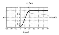
図2は、クランク角度θに対する筒内の燃焼割合MFBの波形を示す図である。ここでは、燃焼割合MFBを、燃焼の進行状態を表す指標として定義している。より具体的には、燃焼割合MFBは、0〜1の範囲で変化するものとし、MFB=0は燃焼開始時点を示し、MFB=1は燃焼終了時点を示すものとしている。
Next, with reference to FIG. 2 and FIG. 3, an in-cylinder pressure Pc information (history) estimation method used in this embodiment will be described.
FIG. 2 is a diagram showing a waveform of the in-cylinder combustion ratio MFB with respect to the crank angle θ. Here, the combustion ratio MFB is defined as an index representing the progress of combustion. More specifically, the combustion rate MFB changes in the range of 0 to 1, MFB = 0 indicates the combustion start time, and MFB = 1 indicates the combustion end time.
図2中に「PVκMFB」を付して示す波形は、PVκ法による計算式、すなわち、次式(1)に従って算出された燃焼割合MFBの波形を示している。
MFB=(PθVθ κ−Pθ0Vθ0 κ)/(PθfVθf κ−Pθ0Vθ0 κ) ・・・(1)
但し、上記(1)式において、Pθ0およびVθ0は、それぞれクランク角度θが所定の燃焼開始時期θ0である場合の筒内圧力Pcおよび筒内容積Vであり、PθfおよびVθfは、それぞれクランク角度θが所定の燃焼終了時期θfである場合の筒内圧力Pcおよび筒内容積Vである。また、PθおよびVθは、それぞれクランク角度θが任意の値である場合の筒内圧力Pcおよび筒内容積Vである。κは、比熱比である。上記(1)式によれば、これら3点の筒内圧力Pcの実測値と筒内容積Vの計算値とに基づいて、燃焼割合MFBの履歴を算出することができる。
The waveform shown with “PV κ MFB” in FIG. 2 shows the calculation formula by the PV κ method, that is, the waveform of the combustion ratio MFB calculated according to the following equation (1).
MFB = (P θ V θ κ -P θ0 V θ0 κ) / (P θf V θf κ -P θ0 V θ0 κ) ··· (1)
However, in the above equation (1), P θ0 and V θ0 are the in-cylinder pressure Pc and the in-cylinder volume V when the crank angle θ is the predetermined combustion start timing θ0, and P θf and V θf are The in-cylinder pressure Pc and the in-cylinder volume V when the crank angle θ is a predetermined combustion end timing θf, respectively. P θ and V θ are the in-cylinder pressure Pc and the in-cylinder volume V, respectively, when the crank angle θ is an arbitrary value. κ is a specific heat ratio. According to the above equation (1), the history of the combustion ratio MFB can be calculated based on the actually measured value of the in-cylinder pressure Pc at these three points and the calculated value of the in-cylinder volume V.
一方、図2中に「WeibeMFB」を付して示す波形は、Weibe関数を用いた計算式、すなわち、次式(2)に従って算出された燃焼割合MFBを示している。
MFB=1−exp[−a{(θ−θ0)/(θf−θ0)}m+1] ・・・(2)
但し、上記(2)式において、aは燃焼速度、mは既定の定数である。
On the other hand, the waveform indicated by “WeibeMFB” in FIG. 2 indicates the calculation ratio using the Weibe function, that is, the combustion ratio MFB calculated according to the following expression (2).
MFB = 1−exp [−a {(θ−θ0) / (θf−θ0)} m + 1 ] (2)
However, in the above equation (2), a is the combustion rate and m is a predetermined constant.
上記(1)式に従って算出された燃焼割合PVκMFBの波形と、上記(2)式に従って算出された燃焼割合WeibeMFBの波形とは、図2に示すように、高い相関性を有している。そこで、本実施形態では、これら2つの式を等価であるものとして、これら2つの式から次式(3)を導き出すこととした。
Pθ=(1/Vθ κ)×〈{1−exp[−a{(θ−θ0)/(θf−θ0)}m+1]}×(PθfVθf κ−Pθ0Vθ0 κ)+Pθ0Vθ0 κ〉 ・・・(3)
As shown in FIG. 2, the waveform of the combustion ratio PV κ MFB calculated according to the above equation (1) and the waveform of the combustion ratio WeibeMFB calculated according to the above equation (2) have high correlation. . Therefore, in the present embodiment, these two expressions are assumed to be equivalent, and the following expression (3) is derived from these two expressions.
P θ = (1 / V θ κ) × <{1-exp [-a {(θ-θ0) / (θf-θ0)} m + 1]} × (P θf V θf κ -P θ0 V θ0 κ) + P θ0 V θ0 κ > (3)
本実施形態のシステムでは、上記(3)式を利用して、内燃機関10の筒内圧力Pcを推定することとしている。以下、図3に示すルーチンを参照して、その推定筒内圧力Pθの算出手法を説明する。
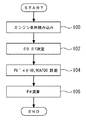
図3は、推定筒内圧力Pθを取得するために、ECU40が実行するルーチンのフローチャートである。図3に示すルーチンでは、先ず、内燃機関10の運転条件、より具体的には、点火時期SA等が取得される(ステップ100)。
In the system of this embodiment, the in-cylinder pressure Pc of the
3, in order to obtain the inside estimated in-cylinder pressure P theta, is a flowchart of a routine that ECU40 performs. In the routine shown in FIG. 3, first, the operating conditions of the
次に、燃焼開始時期θ0および燃焼終了時期θfが決定される(ステップ102)。ECU40は、図4に示すように、燃焼開始時期θ0および燃焼終了時期θfをそれぞれ点火時期SAとの関係で定めたマップを記憶している。尚、図4におけるゼロ点は圧縮上死点を示している。図4に示すマップでは、点火時期SAが進角するにつれ、燃焼開始時期θ0が圧縮上死点に対し、より進角側になるように設定されており、また、点火時期SAが所定の点火時期SA(ここでは、30°BTDC)より進角した場合には、燃焼開始時期θ0がほぼ一定となるように設定されている。燃焼終了時期θfについても、ほぼ同様の傾向に設定されている。
Next, the combustion start timing θ0 and the combustion end timing θf are determined (step 102). As shown in FIG. 4, the
上記ステップ102において、図4に示すマップに従って、現在の点火時期SAに基づく燃焼開始時期θ0および燃焼終了時期θfが決定されると、次いで、−60°ATDCおよび90°ATDCにおけるパラメータ(熱発生量)PVκがそれぞれ算出される(ステップ104)。具体的には、筒内圧センサ32の出力に基づいて、−60°ATDCおよび90°ATDCにおけるそれぞれの筒内圧力Pが取得されると共に、−60°ATDCおよび90°ATDCに対応する筒内容積Vが算出され、それらの値に基づいて、パラメータPVκが算出される。
In
次に、上記(3)式に従って、筒内圧力Pθが算出される(ステップ106)。具体的には、上記ステップ102において決定された燃焼開始時期θ0および燃焼終了時期θfが上記(3)式に代入される。また、上記ステップ104において算出された−60°ATDCにおけるパラメータPVκがパラメータPθ0Vθ0 κとして、また、90°ATDCにおけるパラメータPVκがパラメータPθfVθf κとして、それぞれ代入される。燃焼速度a、および定数mは、共に既定の値が用いられる。その結果、上記(3)式に当該任意のクランク角度θとそのクランク角度θに対応する筒内容積Vθとを代入することにより、任意のクランク角θにおける筒内圧力Pθを算出することが可能となる。また、単位クランク角度θ毎に、それぞれのクランク角度θとそのクランク角度θに対応する筒内容積Vθとを代入することとすれば、推定筒内圧力Pθの履歴を算出することが可能となる。
Next, in-cylinder pressure Pθ is calculated according to the above equation (3) (step 106). Specifically, the combustion start timing θ0 and the combustion end timing θf determined in
図5は、筒内圧力Pとクランク角度θとの関係を表すP−θ線図である。図5中に「CPS」を付して示す波形は、筒内圧センサ32の出力に基づく筒内圧力Pcの実測値を示している。一方、図5中に「Proposed」を付して示す波形は、上記図3に示すルーチンの処理に従って推定された筒内圧力Pθの履歴を示している。図5に示すように、本実施形態の筒内圧力Pcの推定手法によれば、筒内圧力Pcの実測値とほぼ一致した推定筒内圧力Pθを得ることができるのが判る。このように、本実施形態の手法によれば、2点の実測データ(上記図4に示すルーチンの例では、−60°ATDCおよび90°ATDCにおける2点の実測データ)だけで、任意のクランク角度θにおける筒内圧力Pθのデータを取得することが可能となる。
FIG. 5 is a P-θ diagram showing the relationship between the in-cylinder pressure P and the crank angle θ. A waveform indicated by “CPS” in FIG. 5 indicates an actually measured value of the in-cylinder pressure Pc based on the output of the in-
次に、図6を参照して、上記図4に示すルーチンの処理によって取得された推定筒内圧力Pθの履歴を用いて、当該履歴が取得されたサイクルにおける図示トルクの算出手法を説明する。
図6は、推定筒内圧力Pθの履歴を用いて図示トルクを算出するために、ECU40が実行するルーチンのフローチャートである。図6に示すルーチンでは、先ず、単位クランク角度θ毎に、上記図3のルーチンにおけるステップ106の処理を行うことにより、推定筒内圧力Pθの履歴が演算される(ステップ200)。
Next, referring to FIG. 6, using the history of the putative cylinder pressure P theta obtained by processing of the routine shown in FIG. 4, illustrating the method of calculating the indicated torque in the cycle in which the history has been acquired .
6, in order to calculate the indicated torque with the record of the estimated in-cylinder pressure P theta, is a flowchart of a routine that ECU40 performs. In the routine shown in FIG. 6, first, the history of the estimated in-cylinder pressure P θ is calculated by performing the processing of
次に、上記ステップ200において取得された推定筒内圧力Pθの履歴に、筒内容積Vの変化率であるdV/dθを乗ずることにより、図示トルクPθ・dV/dθが算出される(ステップ202)。
Next, the indicated torque P θ · dV / dθ is calculated by multiplying the history of the estimated in-cylinder pressure P θ acquired in
筒内圧センサを備える内燃機関において、図示トルクを正確に求めることを可能とするような高い速度で、筒内圧センサのアナログ出力をディジタル信号に変換することは、現状のECUの性能では困難である。その一方で、ECU内のCPUの演算能力自体は、十分なレベルにある。上記図6に示すルーチンの処理によれば、2点の筒内圧力Pθの実測するのみで筒内圧力Pθの履歴を推定することができ、そしてその履歴から図示トルクPθ・dV/dθを算出することができる。このため、ECU40の性能による制約を受けることなく、リアルタイムで正確な図示トルクPθ・dV/dθを明らかにすることが可能となる。
In an internal combustion engine equipped with an in-cylinder pressure sensor, it is difficult to convert the analog output of the in-cylinder pressure sensor into a digital signal at such a high speed that enables accurate calculation of the indicated torque. . On the other hand, the computing power of the CPU in the ECU is at a sufficient level. According to the processing routine shown in FIG. 6, it is possible to estimate the history of the in-cylinder pressure P theta only be measured in-cylinder pressure P theta two points, and indicated torque P from its history theta · dV / dθ can be calculated. Therefore, it is possible to clarify the indicated torque P θ · dV / dθ that is accurate in real time without being restricted by the performance of the
尚、上述した実施の形態1においては、ECU40が、上記ステップ104の処理を実行することにより前記第1または第2の発明における「熱発生量情報取得手段」が、上記ステップ106において上記(3)式を使用して所定の処理を実行することにより前記第1の発明における「関係情報取得手段」および「圧力推定手段」が、それぞれ実現されている。また、上記(3)式が前記第1または第2の発明における「関係情報」に相当している。
また、筒内圧センサ32が前記第3の発明における「筒内圧力検出手段」に相当している。
In the first embodiment described above, the
Also, the
実施の形態2.
次に、図7および図8を参照して、本発明の実施の形態2について説明する。
本実施形態のシステムは、図1に示すハードウェア構成を用いて、ECU40に図3のルーチンに代えて、図7のルーチンを実行させることにより実現されるものである。より具体的には、本実施形態のシステムでは、燃焼期間中の筒内に生ずるイオンをイオン電流Icとして検出するためのイオンプローブ(イオン電流センサ)として、点火プラグ28が用いられている点が、上述した実施の形態1に対して異なっている。本実施形態のシステムでは、そのようなイオン電流Icを利用して、推定筒内圧力Pθの履歴を取得することとしている。
Next, a second embodiment of the present invention will be described with reference to FIG. 7 and FIG.
The system of the present embodiment is realized by causing the
図7は、上記の機能を実現するために、ECU40が本実施の形態2において実行するルーチンのフローチャートである。図7に示すルーチンでは、先ず、イオン電流Icが所定期間に渡って検出される(ステップ300)。具体的には、ECU40は、イオン電流Icを検出すべく、点火プラグ28による点火の終了後に、当該点火プラグ28の電極に所定の電圧を印加する。イオン電流Icは、その際に、当該電極間に流れる電流として検出されるものである。
FIG. 7 is a flowchart of a routine that the
次に、燃焼開始時期θ0および燃焼終了時期θfが取得される(ステップ302)。図8(A)は、点火プラグ28をイオンプローブとして用いて検出されたイオン電流Icの波形を示している。イオン電流Icは、点火によって燃焼が開始されることで発生し、その後燃焼が終了されると消滅する。このため、図8(A)に示すように、計測されたイオン電流Icの波形に基づいて、燃焼開始時期θ0および燃焼終了時期θfを取得することができる。
Next, the combustion start timing θ0 and the combustion end timing θf are acquired (step 302). FIG. 8A shows a waveform of an ion current Ic detected using the
次に、上記ステップ302において取得された燃焼開始時期θ0から燃焼終了時期θfまでの区間に対して、イオン電流Icの積分値ΣIcが算出される(ステップ304)。図8(B)は、イオン電流Icの積分値ΣIcの波形を示している。ここで、イオン電流Icは、燃焼期間中の熱発生率dQ/dθと高い相関性を有するものである。そのようなイオン電流Icを、図8(B)に示すように、燃焼開始時期θ0から燃焼終了時期θfまでの区間に対して積分した値ΣIcは、燃焼割合MFB(熱発生量)と高い相関性を有するものとなる。 Next, an integral value ΣIc of the ionic current Ic is calculated for the section from the combustion start timing θ0 to the combustion end timing θf acquired in step 302 (step 304). FIG. 8B shows a waveform of the integral value ΣIc of the ion current Ic. Here, the ion current Ic has a high correlation with the heat generation rate dQ / dθ during the combustion period. As shown in FIG. 8B, the value ΣIc obtained by integrating such an ion current Ic with respect to the section from the combustion start timing θ0 to the combustion end timing θf has a high correlation with the combustion ratio MFB (heat generation amount). It will have a sex.
次に、負荷率KLに基づいて、熱発生量PVκが推定される(ステップ306)。内燃機関10の負荷率KLと熱発生量PVκとはリニアな特性を有しており、ここでは、負荷率KLと熱発生量PVκとの関係を定めたマップによって、負荷率KLから熱発生量PVκを推定している。尚、負荷率KLに代え、吸気圧力と吸気温度に基づく筒内DJ値(筒内充填空気量を示す値)と熱発生量PVκとの関係を定めたマップから熱発生量PVκを推定してもよい。
Next, the heat generation amount PV κ is estimated based on the load factor KL (step 306). The load factor KL and the heat generation amount PV κ of the
次に、上記積分値ΣIcが燃焼割合MFBに換算される(ステップ308)。具体的には、筒内空気量等に基づいて積分値ΣIcを補正することにより、積分値ΣIcが今回の燃焼サイクルにおける燃焼割合MFBに対応した値に換算される。次いで、推定筒内圧力Pθが算出される(ステップ310)。具体的には、上記ステップ308において取得されたイオン電流Icに基づく燃焼割合MFBを、上記(3)式中の燃焼割合MFBに相当するWeibe関数の項に代入する。そして、上記ステップ306において取得された熱発生量PVκに基づく値を上記(3)式の残りの項に代入することにより、推定筒内圧力Pθが算出される。
Next, the integral value ΣIc is converted into a combustion ratio MFB (step 308). Specifically, the integral value ΣIc is converted to a value corresponding to the combustion ratio MFB in the current combustion cycle by correcting the integral value ΣIc based on the in-cylinder air amount or the like. Next, the estimated in-cylinder pressure Pθ is calculated (step 310). Specifically, the combustion rate MFB based on the ion current Ic acquired in
図7に示すルーチンを用いて以上説明したイオン電流Icを利用する手法によっても、上記(3)式を利用して、推定筒内圧力Pθを算出することができる。また、このような手法によれば、点火プラグ28をイオンプローブとして用いることができるため、筒内圧センサ32を用いる手法に比して、内燃機関10へのセンサの搭載性の面において有利となる。
By techniques utilizing ion current Ic described above with reference to the routine shown in FIG. 7, it is possible using the above equation (3), calculates the inside estimated in-cylinder pressure P theta. Further, according to such a method, since the
尚、上述した実施の形態2においては、ECU40が、上記ステップ306の処理を実行することにより前記第1または第2の発明における「熱発生量情報取得手段」が、上記ステップ300〜302、308の処理を実行することにより前記第2の発明における「燃焼割合情報取得手段」が、それぞれ実現されている。
また、点火プラグ28が前記第2の発明における「イオン検出手段」に相当している。
In the second embodiment described above, the
The
実施の形態3.
[推定筒内圧力Pθを用いたノック判定]
次に、図9乃至図12を参照して、本発明の実施の形態3について説明する。
本実施形態のシステムにおいても、図1に示すハードウェア構成を用いることとしている。そして、本実施形態においては、上記図3に示すルーチンに従って取得される筒内圧力Pθの推定値を利用して、ノックの有無を判定することを特徴としている。
[Knock determination using estimated in-cylinder pressure P θ ]
Next, a third embodiment of the present invention will be described with reference to FIGS.
Also in the system of this embodiment, the hardware configuration shown in FIG. 1 is used. Then, in the present embodiment, by utilizing the estimated value of the in-cylinder pressure P theta acquired in accordance with the routine shown in FIG. 3, it is characterized by determining the presence or absence of a knock.
図9は、上記の機能を実現するために、本実施の形態3においてECU40が実行するルーチンのフローチャートである。尚、図9において、実施の形態1における図6に示すステップと同一のステップについては、同一の符号を付してその説明を省略または簡略する。図9に示すルーチンでは、先ず、推定筒内圧力Pθの履歴が演算される(ステップ200)。図10(A)は、本ステップ200において演算された筒内圧力Pθの波形の一例を示している。
FIG. 9 is a flowchart of a routine executed by the
次に、筒内圧センサ32の出力に基づいて、実筒内圧力PCの履歴が取得される(ステップ400)。図10(B)は、ノックが実際に発生した場合に、本ステップ400の処理によって取得された実筒内圧力Pcの波形の一例を示している。ノックが発生した場合における実筒内圧力Pcの波形には、図10(B)に示すように、高周波圧力成分が重畳することになる。これに対し、図10(A)に示す推定筒内圧力Pθの波形は、1次遅れ系の関数(上記(3)式)を介して算出されているため、高周波圧力成分がその波形に重畳することはなく、なめらかなものとなる。
Then, based on the output of the
そこで、図9に示すルーチンでは、次いで、上記ステップ200において演算された推定筒内圧力Pθの波形と、上記ステップ400において取得された実筒内圧力Pcの波形との差分が算出される(ステップ402)。本ステップ402の処理によれば、図10(C)に示すように、実筒内圧力Pcの波形からノックに起因する高周波圧力成分のみ(ノック発生に関する情報)を取り出すことができる。
Therefore, in the routine shown in FIG. 9, the difference between the waveform of the estimated in-cylinder pressure P θ calculated in
次に、上記ステップ402において算出された差分の絶対値の積算処理が実行される(ステップ404)。図10(D)は、本ステップ404における積算処理によって得られた波形を示している。次いで、ノック強度の判定が実行される(ステップ406)。具体的には、上記差分の積算値が所定の閾値以上となった場合に、ノックが発生したと判断される。尚、ここでは、上記差分の絶対値の積算値を算出することとしているが、積算値に代えて、差分のピーク値に基づいてノック強度の判定を行うようにしてもよい。
Next, an integration process of the absolute value of the difference calculated in
以上説明した図9に示すルーチンによれば、本発明の推定筒内圧力Pθの履歴を用いて、ノック判定を行うことが可能となる。このような手法によれば、同一の燃焼サイクルにおける推定筒内圧力Pθと実筒内圧力Pcとを比較することができる。このため、前回の燃焼サイクルにおける現象或いは統計から現在の燃焼サイクルにおける正常な筒内圧力を推定するこという従来の手法に比して、より正確なノック検出が可能となる。また、このような手法によれば、ノック発生時の高周波圧力成分を取り出すためのハイパスフィルタ回路をECU40内に備える必要なしに、ノック判定を行うことができる。これにより、当該回路自体のコストを無くすことができ、また、ノイズ対策のために必要となるコストを低減することができる。
According to the routine shown in FIG. 9 described above, the knock determination can be performed using the history of the estimated in-cylinder pressure Pθ of the present invention. According to such a method, the estimated in-cylinder pressure Pθ and the actual in-cylinder pressure Pc in the same combustion cycle can be compared. For this reason, more accurate knock detection is possible as compared with the conventional method of estimating the normal in-cylinder pressure in the current combustion cycle from the phenomenon or statistics in the previous combustion cycle. Further, according to such a method, knock determination can be performed without the need to provide the
ところで、上述した実施の形態3においては、筒内圧力Pcの推定値と実測値とを直接比較してノック判定を行っているが、本発明におけるノック判定手法はこれに限定されるものではなく、例えば、以下の図11および図12を参照して説明する手法であってもよい。図11は、熱発生率dQ/dθの推定値と実測値とを比較してノック判定を行うべく、ECU40が実行するルーチンのフローチャートである。図11に示すルーチンでは、先ず、推定熱発生率dQ/dθの履歴が算出される(ステップ500)。具体的には、上記ステップ200と同様の処理を行うことにより、先ず、推定筒内圧力Pθの履歴を演算し、その演算された推定筒内圧力Pcの履歴から所定の演算式に従って推定熱発生率dQ/dθの履歴を算出している。図12(A)は、本ステップ500において算出された推定熱発生率dQ/dθの波形の一例を示している。
In the third embodiment described above, knock determination is performed by directly comparing the estimated value of the in-cylinder pressure Pc with the actual measurement value. However, the knock determination method in the present invention is not limited to this. For example, a method described with reference to FIGS. 11 and 12 below may be used. FIG. 11 is a flowchart of a routine executed by the
次に、筒内圧センサ32の出力に基づいて取得された実筒内圧力Pcの履歴から、所定の演算式に従って実熱発生率dQ/dθの履歴が算出される(ステップ502)。図12(B)は、ノックが実際に発生した場合に、本ステップ502の処理によって算出された実熱発生率dQ/dθの波形の一例を示している。ノックが発生した場合は、急速燃焼が発生するため、図12(B)に示すように、実熱発生率dQ/dθの波形では、燃焼ピーク値が大きくなり、かつ、燃焼の終了が早くなる。これに対し、推定熱発生率dQ/dθの波形には、図12(A)に示すように、ノックが反映されない。
Next, the history of the actual heat generation rate dQ / dθ is calculated from the history of the actual in-cylinder pressure Pc acquired based on the output of the in-cylinder pressure sensor 32 (step 502) according to a predetermined arithmetic expression. FIG. 12B shows an example of a waveform of the actual heat generation rate dQ / dθ calculated by the processing of
そこで、図11に示すルーチンでは、次いで、上記ステップ500において算出された推定熱発生率dQ/dθの波形と、上記ステップ502において取得された実熱発生率dQ/dθの波形との差分が算出される(ステップ504)。本ステップ504の処理によれば、図12(C)に示すように、実熱発生率dQ/dθの波形からノックの特徴を捉えた部分のみ(ノック発生に関する情報)を取り出すことができる。
Therefore, in the routine shown in FIG. 11, the difference between the estimated heat generation rate dQ / dθ waveform calculated in
次に、上記ステップ504において算出された差分の絶対値の積算処理が実行される(ステップ506)。図12(D)は、本ステップ506における積算処理によって得られた波形を示している。次いで、ノック強度の判定が実行される(ステップ508)。その判定手法は、筒内圧力Pcを用いる場合と同様であるため、その詳細な説明を省略する。以上説明した熱発生率dQ/dθを用いた手法によっても、ノックの有無を判定することができる。この手法を実際に行うにあたって、推定筒内圧力Pθを求める際には、上記図3のルーチンの手法で筒内圧センサ32を用いて筒内状態を検出してもよいし、また、上記図7のルーチンの手法で点火プラグ28をイオンプローブとして用いて筒内状態を検出してもよいが、イオンプローブを用いた手法の方が、高周波成分が発生しないので適している。
Next, an integration process of the absolute value of the difference calculated in
また、上述した実施の形態3においては、上記ステップ404により取得される積算値を所定の閾値と比較することにより、ノックの有無を判定しているが、これに限らず、当該積算値の大小に基づいて、ノックの発生レベルを判定するものであってもよい。また、ノックが生じ易い領域である負荷率KLが高い領域である場合に、図9のルーチンを実行させることによりノック判定を行うこととしてもよい。
In the third embodiment described above, the presence or absence of knocking is determined by comparing the integrated value acquired in
尚、上述した実施の形態3およびその変形例においては、ECU40が上記ステップ402〜406の処理を実行することにより、前記第8の発明における「ノック情報取得手段」が実現されている。
また、ECU40が、上記ステップ500の処理を実行することにより前記第9の発明における「推定熱発生率取得手段」が、上記ステップ502の処理を実行することにより前記第9の発明における「実熱発生率取得手段」が、上記ステップ504〜508の処理を実行することにより前記第9の発明における「ノック情報取得手段」が、それぞれ実現されている。
In the third embodiment and the modification thereof described above, the “knock information acquisition unit” according to the eighth aspect of the present invention is realized by the
Further,
実施の形態4.
[推定筒内圧力Pθを用いたMBT制御]
次に、図13を参照して、本発明の実施の形態4について説明する。
本実施形態のシステムにおいても、図1に示すハードウェア構成を用いることとしている。そして、本実施形態においては、上記図3に示すルーチンに従って取得される推定筒内圧力Pθを利用して、MBT(最適点火時期)制御を実行することを特徴としている。
Embodiment 4 FIG.
[MBT control using the estimated in-cylinder pressure P theta]
Next, a fourth embodiment of the present invention will be described with reference to FIG.
Also in the system of this embodiment, the hardware configuration shown in FIG. 1 is used. Then, in the present embodiment, by using the estimated in-cylinder pressure P theta acquired in accordance with the routine shown in FIG. 3, it is characterized by performing the MBT (optimum ignition timing) control.
図13は、上記の機能を実現するために、本実施の形態4においてECU40が実行するルーチンのフローチャートである。尚、図13において、実施の形態1における図6に示すステップと同一のステップについては、同一の符号を付してその説明を省略または簡略する。図13に示すルーチンでは、先ず、推定筒内圧力Pθの履歴が演算される(ステップ200)。
FIG. 13 is a flowchart of a routine executed by the
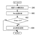
次に、上記ステップ200において算出された推定筒内圧力Pθの履歴中から筒内圧力Pcの最大値Pmaxが生じた位置(タイミング(クランク角度θPmax))が取得される(ステップ600)。次いで、上記ステップ600において取得されたPmaxの位置θPmaxが所定位置θAか否かが判別される(ステップ602)。ECU40は、最大圧力値Pmaxの位置θPmaxが上記所定位置θAであるときに、点火時期SAがMBTであると判断できるように定められた所定位置θAを記憶している。
Next, the position (timing (crank angle θ Pmax )) at which the maximum value Pmax of the in-cylinder pressure Pc occurs is acquired from the history of the estimated in-cylinder pressure P θ calculated in step 200 (step 600). Then, the position theta Pmax of the obtained Pmax in
上記ステップ602において、最大圧力値Pmaxの位置θPmaxが上記所定位置θAであると判断された場合は、現在制御している点火時期SAがMBTであると判断することができる。このため、この場合は、点火時期SAが更に制御されることなく、今回の処理サイクルが終了される。一方、上記ステップ602において、最大圧力値Pmaxの位置θPmaxが上記所定位置θAでないと判断された場合は、次いで、点火時期SAの制御が実行される(ステップ604)。具体的には、算出された最大圧力値Pmaxの位置θPmaxが上記所定位置θAより進角側であると認められた場合には、それらの位置の偏差に基づいて、点火時期SAがMBTとなるように所定量だけ遅角され、一方、その位置θPmaxが上記所定位置θAより遅角側であると認められた場合には、同様に、点火時期SAが所定量だけ進角される。
If it is determined in
筒内圧センサで筒内圧力Pcを実測し、そのピーク値(最大値Pmax)をホールドする手法では、その最大値Pmaxの位置(タイミング)までを検出することができず、また、リアルタイムで筒内圧力Pcの実測値をECU内に取り込むという手法で上記のピーク発生タイミングを検出するためには、ECUによる高速サンプリングが必要となるが、現在のECUの性能では、現実には極めて困難である。これに対し、以上説明した図13に示すルーチンによれば、上述した本願発明による推定筒内圧力Pθの情報(履歴)を用いて、筒内圧力Pcの最大値Pmaxが生じた位置θPmaxを所定位置θAとなるように制御することにより、点火時期SAをMBTに制御することが可能となる。 By measuring the in-cylinder pressure Pc with the in-cylinder pressure sensor and holding the peak value (maximum value Pmax), it is impossible to detect the position (timing) of the maximum value Pmax. In order to detect the above-mentioned peak generation timing by the method of taking the actual measurement value of the pressure Pc into the ECU, high-speed sampling by the ECU is necessary. However, the current ECU performance is extremely difficult in reality. On the other hand, according to the routine shown in FIG. 13 described above, the position θ Pmax where the maximum value Pmax of the in-cylinder pressure Pc is generated using the information (history) of the estimated in-cylinder pressure P θ according to the present invention described above. Is controlled to be at a predetermined position θ A , the ignition timing SA can be controlled to MBT.
尚、上述した実施の形態4においては、ECU40が、上記ステップ200の処理を実行することにより前記第11の発明における「圧力履歴取得手段」が、上記ステップ600の処理を実行することにより前記第11の発明における「最大圧力値発生時期取得手段」が、上記ステップ602および604の処理を実行することにより前記第11の発明における「点火時期制御手段」が、それぞれ実現されている。
In the above-described fourth embodiment, the
実施の形態5.
[推定筒内圧力Pθを用いたリーンリミット制御]
次に、図14を参照して、本発明の実施の形態5について説明する。
本実施形態のシステムにおいても、図1に示すハードウェア構成を用いることとしている。そして、本実施形態においては、上記図3に示すルーチンに従って取得される推定筒内圧力Pθを利用して、希薄燃焼が実現可能な限界空燃比への適切な空燃比制御を可能とすべく、リーンリミット制御を実行することを特徴としている。
[Lean limit control using estimated in-cylinder pressure P θ ]
Next, a fifth embodiment of the present invention will be described with reference to FIG.
Also in the system of this embodiment, the hardware configuration shown in FIG. 1 is used. Then, in the present embodiment, by using the estimated in-cylinder pressure P theta acquired in accordance with the routine shown in FIG. 3, in order to enable a proper air-fuel ratio control to the lean combustion is feasible limit air-fuel ratio It is characterized by executing lean limit control.
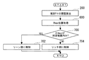
図14は、上記の機能を実現するために、本実施の形態5においてECU40が実行するルーチンのフローチャートである。尚、図14において、実施の形態1における図6に示すステップと同一のステップについては、同一の符号を付してその説明を省略または簡略する。図14に示すルーチンでは、先ず、推定筒内圧力Pθの履歴が演算され(ステップ200)、次いで、その推定筒内圧力Pθの履歴中から最大圧力値Pmaxが生じた位置(タイミング(クランク角度θPmax))が取得される(ステップ600)。
FIG. 14 is a flowchart of a routine executed by the
次に、上記ステップ600において取得された最大圧力値Pmaxの位置θPmaxがクランク角度θの所定範囲内にあるか否かが判別される(ステップ700)。内燃機関10では、空燃比をリーン側に変更していった結果として燃焼悪化や失火が生ずると、最大圧力値Pmaxの値が小さくなると共に、その最大圧力値Pmaxが発生するタイミング(クランク角度θPmax)が正常に燃焼が行われた場合に比して変化する。ECU40は、空燃比をリーン側に制御したことによるそのようなタイミングθPmaxの変化を捉えることができるように、予め定められた上記のクランク角度θの所定範囲を示す情報を記憶している。
Next, it is determined whether or not the position θ Pmax of the maximum pressure value Pmax acquired in
上記ステップ700において、最大圧力値Pmaxの位置θPmaxが上記所定範囲内にあると判断された場合は、未だリーンリミット(リーン側で正常に燃焼可能な限界空燃比の値)に達していないと判断することができる。この場合は、次いで、空燃比が更にリーンとなるように燃料噴射量が制御される(ステップ702)。一方、上記ステップ700において、最大圧力値Pmaxの位置θPmaxが上記所定範囲内にないと判断された場合は、リーンリミットを超えて燃焼悪化等が生じているものと判断することができる。この場合は、次いで、空燃比がよりリッチとなるように燃料噴射量が制御される(ステップ704)。
If it is determined in
以上説明した図14に示すルーチンによれば、車載ECUの性能が上述したような性能であっても、上述した本願発明による推定筒内圧力Pθの情報(履歴)を用いたことで、最大圧力値Pmaxの位置θPmaxを上記所定範囲内に収まるようにしつつ、空燃比を極限までリーン側に制御していくことが可能となる。 According to the routine shown in FIG. 14 described above, even if the performance of the in-vehicle ECU is the above-described performance, the information (history) of the estimated in-cylinder pressure P θ according to the present invention described above is used. while the position theta Pmax pressure value Pmax to fit within the predetermined range, it is possible to continue to leaner air-fuel ratio to the limit.
また、上述した実施の形態5においては、最大圧力値Pmaxの位置θPmaxに基づいて、空燃比を制御することとしているが、本発明における最大圧力値情報はこれに限られるものではない。例えば、最大圧力値Pmaxの位置θPmaxに加え、当該Pmaxの値の大小を考慮して空燃比を制御してもよい。
In
尚、上述した実施の形態5においては、ECU40が、上記ステップ600の処理を実行することにより前記第12の発明における「最大圧力値情報取得手段」が、上記ステップ700〜704の処理を実行することにより前記第12の発明における「空燃比制御手段」が、それぞれ実現されている。
In the above-described fifth embodiment, the
実施の形態6.
[推定筒内圧力Pθを用いたセンサ出力ずれ補正およびセンサの劣化検出]
次に、図15を参照して、本発明の実施の形態6について説明する。
本実施形態のシステムにおいても、図1に示すハードウェア構成を用いることとしている。そして、本実施形態においては、上記図3に示すルーチンに従って取得される推定筒内圧力Pθを利用して、筒内圧センサ32のセンサ出力ずれの補正および当該センサ32の劣化検出を実行することを特徴としている。
Embodiment 6 FIG.
[Sensor output deviation correction and sensor deterioration detection using estimated in-cylinder pressure Pθ ]
Next, a sixth embodiment of the present invention will be described with reference to FIG.
Also in the system of this embodiment, the hardware configuration shown in FIG. 1 is used. Then, in this embodiment, be utilized to estimate cylinder pressure P theta acquired in accordance with the routine shown in FIG. 3, to perform the correction and detecting deterioration of the
図15は、上記の機能を実現するために、本実施の形態6においてECU40が実行するルーチンのフローチャートである。尚、図15において、実施の形態1における図6に示すステップと同一のステップについては、同一の符号を付してその説明を省略または簡略する。図15に示すルーチンでは、先ず、推定筒内圧力Pθの履歴が演算され(ステップ200)、次いで、筒内圧センサ32の出力に基づいて、実筒内圧力Pcの履歴が取得される(ステップ800)。
FIG. 15 is a flowchart of a routine executed by the
次に、上記ステップ200において演算された推定筒内圧力Pθの履歴と、上記ステップ800において取得された実筒内圧力Pcの履歴とを比較して、筒内圧センサ32の出力のずれに起因して生ずる圧力履歴中の歪み(ヒステリシス)が検知される(ステップ802)。上述した本願発明の手法によって算出される推定筒内圧力Pθの履歴には、上記のような歪みが重畳しない。このため、上記のように筒内圧力Pcの推定値と実測値とを比較することにより、圧力履歴中の歪み、すなわち、筒内圧センサ32の出力ずれを検知することができる。
Next, the history of the estimated in-cylinder pressure P θ calculated in the
次に、上記ステップ802において検知された歪みに基づいて、筒内圧センサ32の出力ずれが補正される(ステップ804)。次いで、上記ステップ802において検知された歪みが所定値より大きいか否かが判別され(ステップ806)、その結果、歪みが所定値よりも大きいと認められた場合は、筒内圧センサ32が劣化していると判定される(ステップ808)。尚、上記ステップ806における劣化判定では、歪みを所定値と比較しているが、これに限らず、上記ステップ804における歪みの補正値が所定値より大きいか否かを判別することとしてもよい。
Next, the output deviation of the in-
以上説明した図15に示すルーチンによれば、同一の燃焼サイクルにおける推定筒内圧力Pθと実筒内圧力Pcとを比較することができる。このため、前回の燃焼サイクルにおける現象或いは統計から現在の燃焼サイクルにおける正常な筒内圧力を推定するこという従来の手法に比して、より正確にセンサ誤差を把握することが可能となる。 According to the routine shown in FIG. 15 described above, the estimated in-cylinder pressure Pθ and the actual in-cylinder pressure Pc in the same combustion cycle can be compared. For this reason, it becomes possible to grasp the sensor error more accurately as compared with the conventional method of estimating the normal in-cylinder pressure in the current combustion cycle from the phenomenon or statistics in the previous combustion cycle.
ところで、上述した実施の形態6においては、筒内圧センサ32を用いて推定した筒内圧力Pθの履歴を実筒内圧力Pcとの比較のために用いているが、本発明における推定筒内圧力Pθを用いた筒内圧センサ32の出力ずれ補正および当該センサ32の劣化検出手法は、これに限定されるものではない。例えば、イオンプローブを用いて行う上記図7に示すルーチンの手法によって推定された筒内圧力Pθと、筒内圧センサ32の実測値との比較によって、同様のセンサ出力ずれ補正やセンサ劣化検出を行ってもよい。そして、このような手法を用いた場合には、イオンプローブおよび筒内圧センサ32の相互の劣化検出も可能となる。
Incidentally, in the above-described sixth embodiment, the history of the in-cylinder pressure P θ estimated using the in-
尚、上述した実施の形態6においては、ECU40が、上記ステップ802の処理を実行することにより前記第13の発明における「歪み検出手段」が、上記ステップ804の処理を実行することにより前記第13の発明における「センサ出力補正手段」が、それぞれ実現されている。
また、ECU40が、上記ステップ806および808の処理を実行することにより、前記第14の発明における「センサ劣化判定手段」が実現されている。
Incidentally, in the sixth embodiment described above,
Further, the
実施の形態7.
[機関回転数NEに基づく実筒内圧力Pcのサンプリング周期変更]
次に、図16を参照して、本発明の実施の形態7について説明する。
本実施形態のシステムにおいても、図1に示すハードウェア構成を用いることとしている。機関回転数NEが高くなると、クランク角度θの角速度が高くなるため、所定クランク角度θの間隔(時間)が短くなる。このため、筒内圧センサ32の出力に基づくECU40による実筒内圧力Pcの計測(サンプリング)は、機関回転数NEが高くなるほど困難となる。そこで、本実施形態では、機関回転数NEに基づいて、実筒内圧力Pcのサンプリング周期を変更することとした。
Embodiment 7 FIG.
[Change in sampling cycle of actual in-cylinder pressure Pc based on engine speed NE]
Next, a seventh embodiment of the present invention will be described with reference to FIG.
Also in the system of this embodiment, the hardware configuration shown in FIG. 1 is used. As the engine speed NE increases, the angular speed of the crank angle θ increases, so the interval (time) of the predetermined crank angle θ decreases. For this reason, the measurement (sampling) of the actual in-cylinder pressure Pc by the
図16は、上記の機能を実現するために、本実施の形態7においてECU40が実行するルーチンのフローチャートである。図16に示すルーチンでは、先ず、機関回転数NEが取得される(ステップ900)。次いで、現在の機関回転数NEが所定値より大きいか否かが判別される(ステップ902)。
FIG. 16 is a flowchart of a routine executed by the
上記ステップ902において、機関回転数NEが所定値以下であると判定された場合は、筒内圧センサ32による筒内圧力Pcの実測値が各種のエンジン制御のための基礎として利用される(ステップ904)。一方、機関回転数NEが所定値より大きいと判定された場合は、上記(3)式に従って算出された推定筒内圧力Pθが各種のエンジン制御のための基礎として利用される(ステップ906)。具体的には、ここでは、例えば、単位クランク角度θ毎に、上記図3のルーチンにおけるステップ106の処理を行うことにより、推定筒内圧力Pθの履歴が演算される。
If it is determined in
既述したように、上記(3)式を用いた筒内圧力Pcの推定手法によれば、2点の実測データだけで、任意のクランク角度θにおける筒内圧力Pcを簡便かつ高精度に推定することができる。このため、上記図16に示すルーチンによれば、機関回転数NEが高い領域において、ECU40のサンプリング周期を落とすことにより、ECU40の負荷を軽減することができる。また、例えば、上述した実施の形態3による推定筒内圧力Pθを利用したノック判定を行うシステムにおいて、本ルーチンの処理を並行して行うこととすれば、機関回転数NEが高い領域におけるノック判定時のECU40の負荷を軽減することができる。
As described above, according to the in-cylinder pressure Pc estimation method using the above equation (3), the in-cylinder pressure Pc at an arbitrary crank angle θ can be estimated simply and with high accuracy using only two points of actually measured data. can do. Therefore, according to the routine shown in FIG. 16, the load on the
尚、上述した実施の形態7においては、ECU40が上記ステップ902および906の処理を実行することにより、前記第15の発明における「制御基礎データ選択手段」が実現されている。
In the seventh embodiment described above, the “control basic data selection means” according to the fifteenth aspect of the present invention is realized by the
実施の形態8.
[推定筒内圧力Pθを用いたトルクデマンド制御の第1の例]
次に、図17および図18を参照して、本発明の実施の形態8について説明する。
本実施形態のシステムにおいても、図1に示すハードウェア構成を用いることとしている。そして、本実施形態は、上記(3)式に従って算出される推定筒内圧力Pθを利用して、内燃機関10の実図示トルクが車両走行状態に基づく要求トルクとなるように制御する手法である。
Embodiment 8 FIG.
[First example of torque demand control using estimated in-cylinder pressure Pθ ]
Next, an eighth embodiment of the present invention will be described with reference to FIG. 17 and FIG.
Also in the system of this embodiment, the hardware configuration shown in FIG. 1 is used. Then, the present embodiment, the (3) by using the estimated in-cylinder pressure P theta calculated according to Formula a technique of controlling so that the actual indicated torque of the
図17は、上記の機能を実現するために、本実施の形態8においてECU40が実行するルーチンのフローチャートである。尚、本ルーチンは、内燃機関10の燃焼サイクル毎に、燃焼開始前の所定のタイミングで実行されるものとする。図17に示すルーチンでは、先ず、現在の車両走行状態が各種のセンサ出力を用いて検知される(ステップ1000)。具体的には、アクセルペダルの踏み込み量やその変化率、機関回転数NE、および車速等の情報が取得される。次いで、それらの車両走行状態に基づいて、ドライバーからの要求を満たすために内燃機関10が発生すべき要求トルクが算出される(ステップ1002)。
FIG. 17 is a flowchart of a routine executed by the
次に、前回の燃焼サイクル分の図示トルクが算出される(ステップ1004)。具体的には、前回サイクルの図示トルクが上記図6のルーチンと同様の手法で算出される。次いで、上記図示トルクが上記要求トルクとなるような点火時期SAが推定される(ステップ1006)。 Next, the indicated torque for the previous combustion cycle is calculated (step 1004). Specifically, the indicated torque of the previous cycle is calculated by the same method as in the routine of FIG. Next, the ignition timing SA is estimated so that the indicated torque becomes the required torque (step 1006).
本ステップ1006においては、より具体的には、次の図18に示すルーチンの処理が実行される。すなわち、先ず、点火時期SAの初期値が設定され(ステップ1100)、次いで、燃焼開始時期θ0および燃焼終了時期θfが、上記ステップ1100または後述するステップ1112において設定された点火時期SAに基づいて、上記図4に示すマップに従って推定される(ステップ1102)。次いで、前回の燃焼サイクルにおける所定の2点の筒内圧力Pcの実測データに基づく熱発生量PVκを上記(3)式に代入して、筒内圧力Pcが推定される(ステップ1104)。次いで、その推定筒内圧力Pcを用いて図示トルクが計算される(ステップ1106)。
More specifically, in
次に、上記ステップ1002において算出された要求トルクと、上記ステップ1106において算出された図示トルクとが一致しているか否かが判別される(ステップ1108)。その結果、それらが一致していないと判定された場合は、次いで、点火時期SAが進角側或いは遅角側に変更され(ステップ1110)、その変更後の点火時期SAを用いて、上記ステップ1102〜1108の処理が再度実行される。一方、上記要求トルクと上記図示トルクとが一致していると認められた場合は、その際の点火時期SAが推定値として最終決定される(ステップ1112)。
Next, it is determined whether or not the required torque calculated in
図17に示すルーチンでは、次に、今回の燃焼サイクルに対する点火時期SAが、上記ステップ1006において算出された点火時期SAとなるように制御される(ステップ1008)。次いで、燃焼が実行された後に、今回の燃焼サイクルの実図示トルクが計算される(ステップ1010)。ここでは、今回の燃焼サイクルにおける所定の2点の筒内圧力Pcの実測データに基づく熱発生量PVκを上記(3)式に代入して、実図示トルクが計算される。 In the routine shown in FIG. 17, next, the ignition timing SA for the current combustion cycle is controlled to be the ignition timing SA calculated in step 1006 (step 1008). Next, after the combustion is executed, the actual indicated torque of the current combustion cycle is calculated (step 1010). Here, the actual indicated torque is calculated by substituting the heat generation amount PV κ based on the actually measured data of the in-cylinder pressure Pc at two predetermined points in the current combustion cycle into the above equation (3).
次に、上記ステップ1010において算出された今回の燃焼サイクルの実図示トルクが、上記ステップ1002において算出された要求トルクと比較され、それらの偏差が算出される(ステップ1012)。次いで、上記ステップ1012において算出された偏差に基づいて、次回の燃焼サイクルの要求トルクが修正される(ステップ1014)。例えば、実図示トルクが要求トルクに達していなかった場合は、次回の燃焼サイクルにおける要求トルクが増大するように修正される。
Next, the actual indicated torque of the current combustion cycle calculated in
以上説明した図17に示すルーチンによれば、上記(3)式に従って取得された推定筒内圧力Pcを利用して、前回の燃焼サイクルの図示トルクを取得することができる。また、上記(3)式に従って取得された推定筒内圧力Pcを利用して、今回の燃焼サイクルの実図示トルクが要求トルクとなるような点火時期SAを推定することができる。更に、そのような点火時期SAの下で発生した今回の燃料サイクルの実図示トルクに基づいて、次回の燃焼サイクルの要求トルクが修正される。このように、本実施形態のシステムによれば、上記(3)式に従って取得された推定筒内圧力Pcに基づいて、内燃機関10のトルクが所望の要求トルクとなるように制御することができる。
According to the routine shown in FIG. 17 described above, the indicated torque of the previous combustion cycle can be acquired using the estimated in-cylinder pressure Pc acquired according to the above equation (3). Further, by using the estimated in-cylinder pressure Pc obtained according to the above equation (3), it is possible to estimate the ignition timing SA such that the actual indicated torque of the current combustion cycle becomes the required torque. Further, the required torque of the next combustion cycle is corrected based on the actual illustrated torque of the current fuel cycle generated under such ignition timing SA. Thus, according to the system of the present embodiment, it is possible to control the torque of the
尚、上述した実施の形態8においては、ECU40が、上記ステップ1000および1002の処理を実行することにより前記第16の発明における「要求トルク取得手段」が、上記ステップ1004および1006の処理を実行することにより前記第16の発明における「制御指標決定手段」が、それぞれ実現されている。
In the above-described eighth embodiment, the
実地の形態9.
[推定筒内圧力Pθを用いたトルクデマンド制御の第2の例]
次に、図19および図20を参照して、本発明の実施の形態9について説明する。
本実施形態のシステムにおいても、図1に示すハードウェア構成を用いることとしている。そして、本実施形態は、上述した実施の形態8と同様に、上記(3)式に従って算出される推定筒内圧力Pθを利用して、内燃機関10の実図示トルクが車両走行状態に基づく要求トルクとなるように制御する手法である。本実施形態においては、前回の燃焼サイクルの図示トルクではなく、今回の燃焼サイクルで内燃機関10が発生させ得るトルクを予め推定し、そして、今回の燃焼サイクルの実図示トルクが要求トルクとなるような点火時期SAを推定している点が、上記実施の形態8と異なっている。
8. Practical form
[Second Example of Torque Demand Control Using Estimated In-Cylinder Pressure P θ ]
Next, Embodiment 9 of the present invention will be described with reference to FIG. 19 and FIG.
Also in the system of this embodiment, the hardware configuration shown in FIG. 1 is used. The present embodiment, like the eighth embodiment described above, the (3) by using the estimated in-cylinder pressure P theta calculated according to Formula actual indicated torque of the
図19は、上記の機能を実現するために、本実施の形態9においてECU40が実行するルーチンのフローチャートである。尚、図19において、実施の形態8における図17に示すステップと同一のステップについては、同一の符号を付してその説明を省略または簡略する。図19に示すルーチンでは、要求トルクが算出された後(ステップ1002)、今回の燃焼サイクルにおける筒内充填空気量が算出される(ステップ1200)。具体的には、筒内DJ値或いは当該空気量と、内燃機関10の各種運転パラメータとの関係を定めた関係式(エアモデル)によって、筒内充填空気量を算出することができる。
FIG. 19 is a flowchart of a routine executed by the
次に、上記ステップ1200において算出された筒内充填空気量に基づいて、今回の燃焼サイクルにおいて、内燃機関10が発生させ得る最大の予測トルクが算出される(ステップ1202)。次いで、上記予測トルクに基づいて、今回の燃焼サイクルの実図示トルクが上記要求トルクとなるような点火時期SAが推定される(ステップ1204)。
Next, the maximum predicted torque that can be generated by the
本ステップ1204においては、より具体的には、次の図20に示すルーチンの処理が実行される。図20に示すルーチンは、基本的には上記図18に示すルーチンと同様であるため、異なる点を中心に説明する。すなわち、図20に示すルーチンでは、燃焼開始時期θ0および燃焼終了時期θfが推定された後(ステップ1102)、上記ステップ1200において算出された筒内空気量に基づいて、図示しないマップを参照して熱発生量PVκが推定される(ステップ1300)。次いで、その熱発生量PVκを上記(3)式に代入して、筒内圧力Pcが推定される(ステップ1104)。
More specifically, in
図20に示すルーチンの処理により点火時期SAが推定された後は、図19に示すルーチンにおいて、上記ステップ1008〜1014の一連の処理が実行される。
以上説明した図19に示すルーチンによれば、上記(3)式に従って取得された推定筒内圧力Pcを利用して、今回の燃焼サイクルで内燃機関10が発生させ得る予測トルクに基づいて、今回の燃焼サイクルの実図示トルクが要求トルクとなるような点火時期SAを推定することができる。更に、そのような点火時期SAの下で発生した今回の燃料サイクルの実図示トルクに基づいて、次回の燃焼サイクルの要求トルクが修正される。このように、本実施形態のシステムによれば、上記(3)式に従って取得された推定筒内圧力Pcに基づいて、内燃機関10のトルクが所望の要求トルクとなるように制御することができる。
After the ignition timing SA has been estimated by the routine shown in FIG. 20, the series of
According to the routine shown in FIG. 19 described above, based on the predicted torque that can be generated by the
尚、上述した実施の形態9においては、ECU40が上記ステップ1200〜1204の処理を実行することにより、前記第16の発明における「制御指標決定手段」が実現されている。
In the ninth embodiment described above, the “control index determination means” according to the sixteenth aspect of the present invention is realized by the
実施の形態10.
[推定筒内圧力Pθを用いたトルクデマンド制御の第3の例]
次に、図21を参照して、本発明の実施の形態10について説明する。
本実施形態のシステムにおいても、図1に示すハードウェア構成を用いることとしている。本実施形態では、上記(3)式に従って算出される推定筒内圧力Pθを利用して、要求トルクに対応する要求筒内圧力が得られるように、筒内圧力Pcを決定するための各種のパラメータを決定することとしている。
[Third example of torque demand control using estimated in-cylinder pressure Pθ ]
Next,
Also in the system of this embodiment, the hardware configuration shown in FIG. 1 is used. In the present embodiment, the (3) by using the estimated in-cylinder pressure P theta calculated according equation, as the required cylinder pressure corresponding to the required torque is obtained, various for determining the in-cylinder pressure Pc The parameters are to be determined.
図21は、上記の機能を実現するために、本実施の形態10においてECU40が実行するルーチンのフローチャートである。図21に示すルーチンでは、先ず、アクセルペダル開度や機関回転数NE等の車両走行状態に基づいて、内燃機関10の要求トルクが算出される(ステップ1400)。次いで、上記ステップ1400において算出された要求トルクが、当該要求トルクを満たすために各気筒の筒内で発生されるべき要求筒内圧力に置き換えられる(ステップ1402)。
FIG. 21 is a flowchart of a routine executed by the
次に、上記ステップ1402において算出された要求筒内圧力と等しい推定筒内圧力Pcが上記(3)式に従って算出されるように、当該(3)式中の各パラメータが決定される(ステップ1404)。それらのパラメータとは、燃焼開始時期θ0、燃焼終了時期θf、燃焼速度a、定数m、およびゲインGである。尚、ゲインGは、筒内空気量に依存する値であり、上記(3)式におけるWeibe関数に関する項(上記(2)式の右辺に相当する項)に乗じられるものである。
Next, each parameter in the equation (3) is determined so that the estimated in-cylinder pressure Pc equal to the required in-cylinder pressure calculated in
次に、上記ステップ1404において決定された各種パラメータの値に基づいて、各アクチュエータの制御量が決定され、当該制御量に基づいて各アクチュエータが制御される(ステップ1406)。具体的には、燃焼開始時期θ0および燃焼終了時期θfに基づいて、上記図4に示すようなマップを参照することで点火時期SAが決定される。また、燃焼速度aに基づいて、可変バルブタイミング機構による吸気弁22や排気弁24の位相の制御量VVT(バルブオーバーラップ量)が決定される。また、ゲインGに基づいて、スロットル開度TAが決定される。尚、ここでは、燃焼速度aに基づいて制御量VVTが決定されているが、これに限らず、燃焼速度aに基づいて、制御量VVTに代え、またはそれと共に、吸気弁22のリフト量を決定してもよい。また、ゲインGに基づいて、スロットル開度TAが決定されているが、これに限らず、ゲインGに基づいて、スロットル開度TAに代え、またはそれと共に、吸気弁22の開弁期間を決定してもよい。また、定数mは、ここでは固定値としているが、急速燃焼が生ずる場合は、この定数mを大きくするとよい。
Next, the control amount of each actuator is determined based on the values of the various parameters determined in
以上説明した図21に示すルーチンによれば、上記(3)式を利用して、要求筒内圧(要求トルク)を得るために必要な各パラメータ(θ0、θf、a等)が決定され、それらのパラメータに従って、内燃機関10のトルク(燃焼)を制御するための各アクチュエータ(電子制御式スロットルバルブ、可変バルブタイミング機構等)が制御される。つまり、本実施形態のシステムによれば、上記(3)式を利用することで、所望の要求トルク(それに対応する要求筒内圧力)に基づいてトルク(燃焼)を制御することが可能となる。また、本実施形態のシステムによれば、上記のように決定されたパラメータによって、バルブのオーバーラップ量や点火時期SA等の制御を、吸入空気量の過不足や点火時期SAの遅角等なしに行うことが可能となる。
According to the routine shown in FIG. 21 described above, parameters (θ0, θf, a, etc.) necessary for obtaining the required in-cylinder pressure (required torque) are determined using the above equation (3). In accordance with these parameters, each actuator (electronically controlled throttle valve, variable valve timing mechanism, etc.) for controlling the torque (combustion) of the
尚、上述した実施の形態10においては、ECU40が上記ステップ1404の処理を実行することにより、前記第16の発明における「制御指標決定手段」が実現されている。
また、ECU40が上記ステップ1402の処理を実行することにより、前記第17の発明における「要求筒内圧取得手段」が実現されている。
また、ECU40が上記ステップ1406の処理を実行することにより、前記第19の発明における「制御手段」が実現されている。
In the tenth embodiment described above, the “control index determining means” according to the sixteenth aspect of the present invention is realized by the
Further, the “required in-cylinder pressure acquisition means” according to the seventeenth aspect of the present invention is realized by the
Further, the “control means” according to the nineteenth aspect of the present invention is realized by the
10 内燃機関
12 ピストン
28 点火プラグ
32 筒内圧センサ
40 ECU(Electronic Control Unit)
a 燃焼速度
dQ/dθ 熱発生率
G ゲイン
Ic イオン電流
m 定数
MFB 燃焼割合
PVκ 熱発生量
Pθ 推定筒内圧力
θ0 燃焼開始時期
θf 燃焼終了時期
DESCRIPTION OF
a Burning speed
dQ / dθ Heat generation rate
G gain
Ic Ion current
m constant
MFB combustion rate
PV κ heat generation
P θ Estimated in-cylinder pressure θ0 Combustion start timing θf Combustion end timing
Claims (19)
燃焼開始時期における熱発生量情報、燃焼終了時期における熱発生量情報、並びに、当該燃焼開始時期および当該燃焼終了時期以外の少なくとも1点のクランク角度における熱発生量情報に基づいて内燃機関の筒内における燃焼割合情報を表す第1関係情報と、前記燃焼開始時期、前記燃焼終了時期、および燃焼速度をパラメータとして含むWeibe関数に基づいて燃焼割合情報を表す第2関係情報とから導出される、前記少なくとも1点のクランク角度における筒内圧力についての関係情報を取得する関係情報取得手段と、
前記関係情報に基づいて筒内圧力を推定する圧力推定手段と、
を備えることを特徴とする内燃機関の制御装置。 Heat generation amount information acquisition means for acquiring heat generation amount information of the internal combustion engine;
Based on the heat generation amount information at the combustion start timing, the heat generation amount information at the combustion end timing, and the heat generation amount information at at least one crank angle other than the combustion start timing and the combustion end timing, Derived from the first relation information representing the combustion ratio information and the second relation information representing the combustion ratio information based on the Weibe function including the combustion start timing, the combustion end timing, and the combustion speed as parameters, Relationship information acquisition means for acquiring relationship information about in-cylinder pressure at at least one crank angle ;
Pressure estimating means for estimating an in-cylinder pressure based on the relationship information;
A control device for an internal combustion engine, comprising:
燃焼時に筒内に生ずるイオンを検出するイオン検出手段と、
前記イオンの検出値に基づいて、内燃機関の筒内における燃焼割合情報を取得する燃焼割合情報取得手段と、
燃焼開始時期における熱発生量情報、燃焼終了時期における熱発生量情報、並びに、当該燃焼開始時期および当該燃焼終了時期以外の少なくとも1点のクランク角度における熱発生量情報に基づいて内燃機関の筒内における燃焼割合情報を表す第1関係情報と、前記イオンの検出値に基づく前記燃焼割合情報とから導出される、前記少なくとも1点のクランク角度における筒内圧力についての関係情報を取得する関係情報取得手段と、
前記関係情報に基づいて筒内圧力を推定する圧力推定手段と、
を備えることを特徴とする内燃機関の制御装置。 Heat generation amount information acquisition means for acquiring heat generation amount information of the internal combustion engine;
Ion detecting means for detecting ions generated in the cylinder during combustion;
Combustion rate information acquisition means for acquiring combustion rate information in a cylinder of the internal combustion engine based on the detected value of the ions;
Based on the heat generation amount information at the combustion start timing, the heat generation amount information at the combustion end timing, and the heat generation amount information at at least one crank angle other than the combustion start timing and the combustion end timing, The relation information acquisition which acquires the relation information about the in-cylinder pressure in the crank angle of the at least one point derived from the 1st relation information showing the combustion ratio information in and the combustion ratio information based on the detected value of the ion Means,
Pressure estimating means for estimating an in-cylinder pressure based on the relationship information;
A control device for an internal combustion engine, comprising:
前記熱発生量情報取得手段は、前記燃焼開始時期および前記燃焼終了時期の2点のクランク角度における筒内圧力の実測値および筒内容積に基づいて熱発生量情報を取得し、
前記圧力推定手段は、前記2点以外のクランク角度における筒内圧力を推定することを特徴とする請求項1記載の内燃機関の制御装置。 In-cylinder pressure detecting means for detecting in-cylinder pressure is further provided,
The heat generation amount information acquisition means acquires heat generation amount information based on an actually measured value and an in-cylinder volume of a cylinder pressure at two crank angles of the combustion start timing and the combustion end timing ,
It said pressure estimating means, a control apparatus for an internal combustion engine according to claim 1, wherein the estimating the in-cylinder pressure at crank angles other than pre SL 2 points.
前記関係情報は、前記イオンの検出値と、筒内充填空気量の情報に基づく熱発生量情報とに基づいて定められることを特徴とする請求項2記載の内燃機関の制御装置。 The heat generation amount information acquisition means acquires heat generation amount information based on the information of the in-cylinder charged air amount,
3. The control apparatus for an internal combustion engine according to claim 2 , wherein the relation information is determined based on a detection value of the ions and heat generation amount information based on information on an in-cylinder charged air amount .
前記圧力推定手段による筒内圧力の推定値と、前記筒内圧力検出手段による筒内圧力の実測値とを比較して、ノック発生に関する情報を取得するノック情報取得手段と、
を備えることを特徴とする請求項1、2、5の何れか1項記載の内燃機関の制御装置。 In-cylinder pressure detecting means for detecting in-cylinder pressure;
Knock information acquisition means for comparing the estimated value of the in-cylinder pressure by the pressure estimation means with the actual measurement value of the in-cylinder pressure by the in-cylinder pressure detection means, and acquiring information relating to the occurrence of knock;
The control device for an internal combustion engine according to any one of claims 1, 2 , and 5 .
前記筒内圧力の実測値に基づいて、熱発生率の実測値を取得する実熱発生率取得手段と、
熱発生率の前記推定値および前記実測値を比較して、ノック発生に関する情報を取得するノック情報取得手段と、
を備えることを特徴とする請求項1、2、5の何れか1項記載の内燃機関の制御装置。 Based on the estimated value of the in-cylinder pressure, estimated heat generation rate acquisition means for acquiring an estimated value of the heat generation rate;
Based on the measured value of the in-cylinder pressure, the actual heat generation rate acquisition means for acquiring the actual value of the heat generation rate;
A knock information acquisition means for comparing the estimated value of the heat generation rate and the actual measurement value to acquire information on the occurrence of knock;
The control device for an internal combustion engine according to any one of claims 1, 2 , and 5 .
前記推定圧力の前記履歴中から筒内圧力の最大値が生ずる時期を取得する最大圧力値発生時期取得手段と、
前記最大値の発生時期が、点火時期がMBTに制御された場合における筒内圧力の最大値の発生時期と等しくなるように、点火時期を制御する点火時期制御手段と、
を備えることを特徴とする請求項1または2記載の内燃機関の制御装置。 Pressure history acquisition means for acquiring a history of estimated in-cylinder pressure by the pressure estimation means in the same combustion cycle;
Maximum pressure value generation timing acquisition means for acquiring a timing at which the maximum value of in-cylinder pressure occurs from the history of the estimated pressure;
An ignition timing control means for controlling the ignition timing so that the generation timing of the maximum value is equal to the generation timing of the maximum value of the in-cylinder pressure when the ignition timing is controlled to MBT;
The control apparatus for an internal combustion engine according to claim 1 or 2, further comprising:
前記推定圧力の前記履歴中から筒内圧力の最大値に関する情報を取得する最大圧力値情報取得手段と、
前記最大値に関する情報に基づいて、空燃比をリーン側或いはリッチ側に制御する空燃比制御手段と、
を備えることを特徴とする請求項1または2記載の内燃機関の制御装置。 Pressure history acquisition means for acquiring a history of estimated in-cylinder pressure by the pressure estimation means in the same combustion cycle;
Maximum pressure value information acquisition means for acquiring information related to the maximum value of in-cylinder pressure from the history of the estimated pressure;
Air-fuel ratio control means for controlling the air-fuel ratio to the lean side or the rich side based on the information about the maximum value;
The control apparatus for an internal combustion engine according to claim 1 or 2, further comprising:
筒内圧力を検出する筒内圧力センサと、
前記推定圧力の履歴と、前記筒内圧力センサによる筒内圧力の実測値の履歴とを比較して、当該実測値の履歴中の歪みを取得する歪み検出手段と、
前記歪みに基づいて、前記筒内圧力センサの出力を補正するセンサ出力補正手段と、
を備えることを特徴とする請求項1または2記載の内燃機関の制御装置。 Pressure history acquisition means for acquiring a history of estimated in-cylinder pressure by the pressure estimation means in the same combustion cycle;
An in-cylinder pressure sensor for detecting the in-cylinder pressure;
A strain detection means for comparing the history of the estimated pressure and the history of the measured value of the in-cylinder pressure by the in-cylinder pressure sensor, and acquiring the strain in the history of the measured value;
Sensor output correcting means for correcting the output of the in-cylinder pressure sensor based on the distortion;
Control apparatus for an internal combustion engine according to claim 1 or 2, wherein further comprising a.
筒内圧力を検出する筒内圧力センサと、
前記推定圧力の履歴と、前記筒内圧力センサによる筒内圧力の実測値の履歴とを比較して、当該実測値の履歴中の歪みを取得する歪み検出手段と、
前記歪みに基づいて、前記筒内圧力センサの劣化判定を行うセンサ劣化判定手段と、
を備えることを特徴とする請求項1または2記載の内燃機関の制御装置。 Pressure history acquisition means for acquiring a history of estimated in-cylinder pressure by the pressure estimation means in the same combustion cycle;
An in-cylinder pressure sensor for detecting the in-cylinder pressure;
A strain detection means for comparing the history of the estimated pressure and the history of the measured value of the in-cylinder pressure by the in-cylinder pressure sensor, and acquiring the strain in the history of the measured value;
Sensor deterioration determination means for determining deterioration of the in-cylinder pressure sensor based on the distortion;
The control apparatus for an internal combustion engine according to claim 1 or 2, further comprising:
内燃機関の熱発生量情報を取得する熱発生量情報取得手段と、
燃焼開始時期における熱発生量情報、燃焼終了時期における熱発生量情報、並びに、当該燃焼開始時期および当該燃焼終了時期以外の少なくとも1点のクランク角度における熱発生量情報に基づいて内燃機関の筒内における燃焼割合情報を表す第1関係情報と、前記燃焼開始時期、前記燃焼終了時期、および燃焼速度をパラメータとして含むWeibe関数に基づいて燃焼割合情報を表す第2関係情報とから導出される、前記少なくとも1点のクランク角度における筒内圧力についての関係情報を取得する関係情報取得手段と、
前記要求トルクと前記関係情報とに基づいて、内燃機関の制御指標となる所定のパラメータを決定する制御指標決定手段と、
を備えることを特徴とする内燃機関の制御装置。 Request torque acquisition means for acquiring the required torque required for the internal combustion engine;
Heat generation amount information acquisition means for acquiring heat generation amount information of the internal combustion engine;
Based on the heat generation amount information at the combustion start timing, the heat generation amount information at the combustion end timing, and the heat generation amount information at at least one crank angle other than the combustion start timing and the combustion end timing, Derived from the first relation information representing the combustion ratio information and the second relation information representing the combustion ratio information based on the Weibe function including the combustion start timing, the combustion end timing, and the combustion speed as parameters, Relationship information acquisition means for acquiring relationship information about in-cylinder pressure at at least one crank angle ;
Control index determining means for determining a predetermined parameter to be a control index of the internal combustion engine based on the required torque and the relationship information;
A control device for an internal combustion engine, comprising:
前記制御指標決定手段は、当該要求筒内圧力と前記関係情報とに基づいて、制御指標となる前記所定のパラメータを決定することを特徴とする請求項16記載の内燃機関の制御装置。 A required in-cylinder pressure acquiring means for acquiring a required in-cylinder pressure corresponding to the required torque,
17. The control apparatus for an internal combustion engine according to claim 16, wherein the control index determining means determines the predetermined parameter serving as a control index based on the required in-cylinder pressure and the relationship information.
Priority Applications (5)
| Application Number | Priority Date | Filing Date | Title |
|---|---|---|---|
| JP2005221160A JP4380604B2 (en) | 2005-07-29 | 2005-07-29 | Control device for internal combustion engine |
| PCT/JP2006/315250 WO2007013663A1 (en) | 2005-07-29 | 2006-07-26 | Internal combustion engine control apparatus |
| EP06768405.0A EP1910657B1 (en) | 2005-07-29 | 2006-07-26 | Internal combustion engine control apparatus |
| US11/915,213 US7669583B2 (en) | 2005-07-29 | 2006-07-26 | Internal combustion engine control apparatus |
| CN200680027867.XA CN100588828C (en) | 2005-07-29 | 2006-07-26 | Control apparatus for internal combustion engine |
Applications Claiming Priority (1)
| Application Number | Priority Date | Filing Date | Title |
|---|---|---|---|
| JP2005221160A JP4380604B2 (en) | 2005-07-29 | 2005-07-29 | Control device for internal combustion engine |
Publications (3)
| Publication Number | Publication Date |
|---|---|
| JP2007032531A JP2007032531A (en) | 2007-02-08 |
| JP2007032531A5 JP2007032531A5 (en) | 2008-07-03 |
| JP4380604B2 true JP4380604B2 (en) | 2009-12-09 |
Family
ID=37075736
Family Applications (1)
| Application Number | Title | Priority Date | Filing Date |
|---|---|---|---|
| JP2005221160A Expired - Fee Related JP4380604B2 (en) | 2005-07-29 | 2005-07-29 | Control device for internal combustion engine |
Country Status (5)
| Country | Link |
|---|---|
| US (1) | US7669583B2 (en) |
| EP (1) | EP1910657B1 (en) |
| JP (1) | JP4380604B2 (en) |
| CN (1) | CN100588828C (en) |
| WO (1) | WO2007013663A1 (en) |
Families Citing this family (53)
| Publication number | Priority date | Publication date | Assignee | Title |
|---|---|---|---|---|
| US9733625B2 (en) | 2006-03-20 | 2017-08-15 | General Electric Company | Trip optimization system and method for a train |
| US10569792B2 (en) | 2006-03-20 | 2020-02-25 | General Electric Company | Vehicle control system and method |
| US10308265B2 (en) | 2006-03-20 | 2019-06-04 | Ge Global Sourcing Llc | Vehicle control system and method |
| US9950722B2 (en) | 2003-01-06 | 2018-04-24 | General Electric Company | System and method for vehicle control |
| JP4380604B2 (en) * | 2005-07-29 | 2009-12-09 | トヨタ自動車株式会社 | Control device for internal combustion engine |
| US9828010B2 (en) | 2006-03-20 | 2017-11-28 | General Electric Company | System, method and computer software code for determining a mission plan for a powered system using signal aspect information |
| JP2007297992A (en) * | 2006-05-01 | 2007-11-15 | Toyota Motor Corp | Control device for internal combustion engine |
| DE102007007641A1 (en) * | 2007-02-08 | 2008-08-14 | Iav Gmbh Ingenieurgesellschaft Auto Und Verkehr | Method for knock control |
| JP4761072B2 (en) * | 2007-03-14 | 2011-08-31 | トヨタ自動車株式会社 | Ignition timing control device for internal combustion engine |
| JP5056290B2 (en) | 2007-09-12 | 2012-10-24 | トヨタ自動車株式会社 | Fuel cetane number discrimination device for diesel engines |
| US8527183B2 (en) * | 2007-09-20 | 2013-09-03 | General Electric Company | System and method for controlling the fuel injection event in an internal combustion engine |
| JP4893553B2 (en) | 2007-09-25 | 2012-03-07 | トヨタ自動車株式会社 | Control device for internal combustion engine |
| DE102007048650B4 (en) * | 2007-10-10 | 2011-06-09 | Audi Ag | Method and apparatus for optimizing the combustion of diesel fuels with different cetane numbers in a diesel internal combustion engine |
| DE102008004361A1 (en) * | 2008-01-15 | 2009-07-16 | Robert Bosch Gmbh | Method for controlling an internal combustion engine, computer program and control unit |
| JP5167928B2 (en) * | 2008-04-24 | 2013-03-21 | 株式会社デンソー | Combustion control device |
| JP4968594B2 (en) * | 2008-06-05 | 2012-07-04 | トヨタ自動車株式会社 | Control device for internal combustion engine |
| EP2136057B1 (en) * | 2008-06-19 | 2021-12-08 | Vitesco Technologies GmbH | Fuel quality dependent injection timing control for an internal combustion engine |
| FR2936019B1 (en) * | 2008-09-18 | 2010-09-10 | Inst Francais Du Petrole | ABNORMAL COMBUSTION DETECTION METHOD FOR INTERNAL COMBUSTION ENGINES |
| US8301356B2 (en) * | 2008-10-06 | 2012-10-30 | GM Global Technology Operations LLC | Engine out NOx virtual sensor using cylinder pressure sensor |
| DE102009000329A1 (en) * | 2008-10-13 | 2010-04-15 | Robert Bosch Gmbh | Method and device for operating an internal combustion engine |
| JP5077768B2 (en) * | 2008-12-17 | 2012-11-21 | トヨタ自動車株式会社 | Fuel injection control device for internal combustion engine |
| US9834237B2 (en) | 2012-11-21 | 2017-12-05 | General Electric Company | Route examining system and method |
| US8041499B2 (en) | 2009-03-31 | 2011-10-18 | Denso Corporation | Method and apparatus for combustion chamber pressure estimation |
| JP5370207B2 (en) * | 2010-02-19 | 2013-12-18 | トヨタ自動車株式会社 | Control device for internal combustion engine |
| CN102439280B (en) * | 2010-04-19 | 2014-10-22 | 丰田自动车株式会社 | Control device for internal combustion engine |
| CN103348119A (en) | 2010-06-11 | 2013-10-09 | 丰田自动车株式会社 | Control device for internal combustion engine |
| US9163601B2 (en) * | 2011-02-18 | 2015-10-20 | Toyota Jidosha Kabushiki Kaisha | Control device for internal combustion engine |
| WO2012157067A1 (en) * | 2011-05-16 | 2012-11-22 | トヨタ自動車株式会社 | Air/fuel ratio imbalance detection device for internal combustion engine |
| JP5218624B2 (en) * | 2011-10-31 | 2013-06-26 | トヨタ自動車株式会社 | Fuel cetane number discrimination device for diesel engines |
| DE102011089370A1 (en) * | 2011-12-21 | 2013-06-27 | Robert Bosch Gmbh | Method and apparatus for operating a cold start emission control of an internal combustion engine |
| CN102518521B (en) * | 2011-12-27 | 2013-12-25 | 大连理工大学 | Torque estimation method for vehicle engine |
| US10054067B2 (en) * | 2012-02-28 | 2018-08-21 | Wayne State University | Using ion current signal for engine performance and emissions measuring techniques and method for doing the same |
| DE102012203487B4 (en) * | 2012-03-06 | 2014-07-10 | Robert Bosch Gmbh | Method and device for detecting pre-ignition in a gasoline engine |
| JP2013189923A (en) * | 2012-03-14 | 2013-09-26 | Hitachi Automotive Systems Ltd | Control device for internal combustion engine |
| US9669851B2 (en) | 2012-11-21 | 2017-06-06 | General Electric Company | Route examination system and method |
| US20140172277A1 (en) * | 2012-12-18 | 2014-06-19 | Caterpillar Inc. | Engine diagnostic system and method |
| WO2014112267A1 (en) * | 2013-01-17 | 2014-07-24 | 日産自動車株式会社 | Control device and control method for internal combustion engine |
| CA2809291C (en) * | 2013-03-12 | 2014-11-25 | Westport Power Inc. | Fuel system diagnostics |
| SE537190C2 (en) * | 2013-04-25 | 2015-03-03 | Scania Cv Ab | Method and system for controlling an internal combustion engine through control of combustion in an internal combustion chamber during the current combustion cycle |
| JP5874686B2 (en) * | 2013-05-31 | 2016-03-02 | トヨタ自動車株式会社 | Control device for internal combustion engine |
| JP5769785B2 (en) * | 2013-11-20 | 2015-08-26 | 三菱電機株式会社 | Control device for internal combustion engine |
| DE102014007009B4 (en) * | 2014-05-13 | 2018-01-18 | Mtu Friedrichshafen Gmbh | Engine monitoring by means of cylinder-specific pressure sensors excellently with lean gas engines with purged prechamber |
| US9546611B2 (en) * | 2014-10-28 | 2017-01-17 | GM Global Technology Operations LLC | M index determination systems and methods for Wiebe functions |
| JP6420365B2 (en) * | 2014-12-24 | 2018-11-07 | 株式会社ケーヒン | Internal combustion engine control device |
| CN107690520B (en) | 2015-04-14 | 2021-09-14 | 伍德沃德有限公司 | Engine control based on combustion pressure feedback with variable resolution sampling window |
| US9689339B2 (en) * | 2015-06-10 | 2017-06-27 | GM Global Technology Operations LLC | Engine torque control with fuel mass |
| KR102670373B1 (en) | 2016-10-12 | 2024-05-28 | 삼성전자주식회사 | Apparatus for testing semiconductor device and system comprising the same |
| CN106548029A (en) * | 2016-11-01 | 2017-03-29 | 哈尔滨工程大学 | The determination method of the regular empirical coefficient of weber burning |
| EP3765724B1 (en) * | 2018-03-16 | 2021-12-15 | Volvo Truck Corporation | A method for estimating cylinder pressure |
| US10934965B2 (en) | 2019-04-05 | 2021-03-02 | Woodward, Inc. | Auto-ignition control in a combustion engine |
| US11415041B2 (en) * | 2019-09-16 | 2022-08-16 | Woodward, Inc. | Flame triggered and controlled volumetric ignition |
| CN110987452B (en) * | 2019-11-26 | 2021-09-28 | 东北大学 | Internal combustion engine torque soft measurement method based on rotation speed signal |
| JP7403743B2 (en) * | 2020-07-01 | 2023-12-25 | マツダ株式会社 | Engine combustion state prediction method |
Family Cites Families (20)
| Publication number | Priority date | Publication date | Assignee | Title |
|---|---|---|---|---|
| JPS56124673A (en) * | 1980-03-06 | 1981-09-30 | Nissan Motor Co Ltd | Ignition timing controlling device for internal combustion engine |
| JP3237316B2 (en) * | 1993-06-28 | 2001-12-10 | 三菱電機株式会社 | Engine control device |
| JP3179299B2 (en) * | 1993-11-12 | 2001-06-25 | 株式会社コスモ総合研究所 | Spark ignition engine and optimal ignition timing control method |
| JP3331107B2 (en) * | 1996-01-08 | 2002-10-07 | 株式会社ユニシアジェックス | Ignition timing control device for internal combustion engine |
| JP3959781B2 (en) * | 1997-04-21 | 2007-08-15 | 日産自動車株式会社 | Misfire detection device and control device for direct injection spark ignition engine |
| US6089077A (en) * | 1997-06-26 | 2000-07-18 | Cooper Automotive Products, Inc. | Mass fraction burned and pressure estimation through spark plug ion sensing |
| JP3963044B2 (en) * | 1998-06-29 | 2007-08-22 | 日産自動車株式会社 | Control unit for direct injection gasoline engine |
| JP3823553B2 (en) * | 1998-08-12 | 2006-09-20 | 株式会社日立製作所 | Engine combustion control device |
| US6782737B2 (en) * | 2002-04-08 | 2004-08-31 | Cummins, Inc. | System for estimating peak cylinder pressure in an internal combustion engine |
| US7086382B2 (en) * | 2002-11-01 | 2006-08-08 | Visteon Global Technologies, Inc. | Robust multi-criteria MBT timing estimation using ionization signal |
| JP4036138B2 (en) * | 2003-05-02 | 2008-01-23 | 日産自動車株式会社 | Combustion control device for spark ignition internal combustion engine |
| JP2004332659A (en) * | 2003-05-09 | 2004-11-25 | Nissan Motor Co Ltd | Ignition timing control device for internal combustion engine |
| EP1477651A1 (en) * | 2003-05-12 | 2004-11-17 | STMicroelectronics S.r.l. | Method and device for determining the pressure in the combustion chamber of an internal combustion engine, in particular a spontaneous ignition engine, for controlling fuel injection in the engine |
| JP4281445B2 (en) | 2003-07-08 | 2009-06-17 | トヨタ自動車株式会社 | Control device for internal combustion engine and control method for internal combustion engine |
| JP4391774B2 (en) * | 2003-07-17 | 2009-12-24 | トヨタ自動車株式会社 | Control device for internal combustion engine and control method for internal combustion engine |
| EP1571331B1 (en) * | 2004-02-20 | 2010-06-16 | Nissan Motor Co., Ltd. | Ignition timing control system for an internal combustion engine |
| US7142975B2 (en) * | 2004-04-20 | 2006-11-28 | Southwest Research Institute | Virtual cylinder pressure sensor with individual estimators for pressure-related values |
| JP4380604B2 (en) * | 2005-07-29 | 2009-12-09 | トヨタ自動車株式会社 | Control device for internal combustion engine |
| US7431011B2 (en) * | 2006-02-06 | 2008-10-07 | Ut-Battelle, Llc | Method and device for diagnosing and controlling combustion instabilities in internal combustion engines operating in or transitioning to homogeneous charge combustion ignition mode |
| US7277790B1 (en) * | 2006-04-25 | 2007-10-02 | Ut-Battelle, Llc | Combustion diagnostic for active engine feedback control |
-
2005
- 2005-07-29 JP JP2005221160A patent/JP4380604B2/en not_active Expired - Fee Related
-
2006
- 2006-07-26 EP EP06768405.0A patent/EP1910657B1/en not_active Ceased
- 2006-07-26 WO PCT/JP2006/315250 patent/WO2007013663A1/en active Application Filing
- 2006-07-26 US US11/915,213 patent/US7669583B2/en active Active
- 2006-07-26 CN CN200680027867.XA patent/CN100588828C/en not_active Expired - Fee Related
Also Published As
| Publication number | Publication date |
|---|---|
| EP1910657A1 (en) | 2008-04-16 |
| CN101233308A (en) | 2008-07-30 |
| EP1910657B1 (en) | 2018-07-18 |
| CN100588828C (en) | 2010-02-10 |
| JP2007032531A (en) | 2007-02-08 |
| US20090159046A1 (en) | 2009-06-25 |
| WO2007013663A1 (en) | 2007-02-01 |
| US7669583B2 (en) | 2010-03-02 |
Similar Documents
| Publication | Publication Date | Title |
|---|---|---|
| JP4380604B2 (en) | Control device for internal combustion engine | |
| US7200487B2 (en) | System and method for processing an accelerometer signal to assist in combustion quality control in an internal combustion engine | |
| JP2007032531A5 (en) | ||
| BR112015030156B1 (en) | Misfire detection system for internal combustion engine | |
| US7455047B2 (en) | Control unit for an internal combustion engine | |
| US20150315993A1 (en) | Control apparatus for internal combustion engine | |
| JP2007040207A (en) | Controller for internal combustion engine | |
| JP2005291182A (en) | Misfire detection device | |
| JP2017008750A (en) | Control device of internal combustion engine | |
| JP2017025777A (en) | Control device of internal combustion engine | |
| JP4788640B2 (en) | In-cylinder pressure estimation method and cylinder pressure estimation apparatus for internal combustion engine | |
| CN103256166B (en) | Knock control device of internal combustion engine | |
| AU2005306541B2 (en) | System and method for processing an accelerometer signal to assist in combustion quality control in an internal combustion engine | |
| JP4345723B2 (en) | Method for estimating the indicated mean effective pressure of an internal combustion engine | |
| JP4803099B2 (en) | Torque estimation device for variable compression ratio engine | |
| JP4684944B2 (en) | Control device for internal combustion engine | |
| JPH0610278Y2 (en) | Cylinder pressure maximum crank angle position detector | |
| JPS61157741A (en) | Detecting device of intake air quantity | |
| JP2022162284A (en) | Internal combustion engine control device | |
| JPH10169498A (en) | Torque fluctuation amount detector for internal combustion engine | |
| JPH0633396Y2 (en) | Cylinder pressure maximum crank angle position detector | |
| JP2009127466A (en) | Determination device of internal combustion engine | |
| JP2017180120A (en) | Control device of internal combustion engine | |
| JPH10176593A (en) | Torque detection device for internal combustion engine | |
| JP2011080402A (en) | Sensitivity correction device for cylinder internal pressure sensor |
Legal Events
| Date | Code | Title | Description |
|---|---|---|---|
| A521 | Request for written amendment filed |
Free format text: JAPANESE INTERMEDIATE CODE: A523 Effective date: 20080516 |
|
| A621 | Written request for application examination |
Free format text: JAPANESE INTERMEDIATE CODE: A621 Effective date: 20080516 |
|
| TRDD | Decision of grant or rejection written | ||
| A01 | Written decision to grant a patent or to grant a registration (utility model) |
Free format text: JAPANESE INTERMEDIATE CODE: A01 Effective date: 20090901 |
|
| A01 | Written decision to grant a patent or to grant a registration (utility model) |
Free format text: JAPANESE INTERMEDIATE CODE: A01 |
|
| A61 | First payment of annual fees (during grant procedure) |
Free format text: JAPANESE INTERMEDIATE CODE: A61 Effective date: 20090914 |
|
| FPAY | Renewal fee payment (event date is renewal date of database) |
Free format text: PAYMENT UNTIL: 20121002 Year of fee payment: 3 |
|
| R151 | Written notification of patent or utility model registration |
Ref document number: 4380604 Country of ref document: JP Free format text: JAPANESE INTERMEDIATE CODE: R151 |
|
| FPAY | Renewal fee payment (event date is renewal date of database) |
Free format text: PAYMENT UNTIL: 20121002 Year of fee payment: 3 |
|
| FPAY | Renewal fee payment (event date is renewal date of database) |
Free format text: PAYMENT UNTIL: 20131002 Year of fee payment: 4 |
|
| LAPS | Cancellation because of no payment of annual fees |