JP2005291182A - Misfire detection device - Google Patents
Misfire detection device Download PDFInfo
- Publication number
- JP2005291182A JP2005291182A JP2004111371A JP2004111371A JP2005291182A JP 2005291182 A JP2005291182 A JP 2005291182A JP 2004111371 A JP2004111371 A JP 2004111371A JP 2004111371 A JP2004111371 A JP 2004111371A JP 2005291182 A JP2005291182 A JP 2005291182A
- Authority
- JP
- Japan
- Prior art keywords
- cylinder
- crank angle
- parameter
- angular velocity
- fuel
- Prior art date
- Legal status (The legal status is an assumption and is not a legal conclusion. Google has not performed a legal analysis and makes no representation as to the accuracy of the status listed.)
- Pending
Links
- 238000001514 detection method Methods 0.000 title claims abstract description 99
- 238000002485 combustion reaction Methods 0.000 claims abstract description 106
- 239000000446 fuel Substances 0.000 claims description 76
- 230000005856 abnormality Effects 0.000 claims description 32
- 230000003111 delayed effect Effects 0.000 claims description 5
- 230000008859 change Effects 0.000 description 24
- 101100428617 Homo sapiens VMP1 gene Proteins 0.000 description 8
- 101150074162 TDC1 gene Proteins 0.000 description 8
- 102100038001 Vacuole membrane protein 1 Human genes 0.000 description 8
- 239000000498 cooling water Substances 0.000 description 4
- 238000000034 method Methods 0.000 description 4
- 239000000203 mixture Substances 0.000 description 4
- 230000008569 process Effects 0.000 description 4
- 230000007704 transition Effects 0.000 description 4
- 238000010586 diagram Methods 0.000 description 3
- XLYOFNOQVPJJNP-UHFFFAOYSA-N water Substances O XLYOFNOQVPJJNP-UHFFFAOYSA-N 0.000 description 3
- 101150010135 TDC2 gene Proteins 0.000 description 2
- 230000002159 abnormal effect Effects 0.000 description 2
- 230000000694 effects Effects 0.000 description 2
- 238000002347 injection Methods 0.000 description 2
- 239000007924 injection Substances 0.000 description 2
- 238000005259 measurement Methods 0.000 description 2
- 230000007246 mechanism Effects 0.000 description 2
- 239000002184 metal Substances 0.000 description 2
- 230000007423 decrease Effects 0.000 description 1
- 230000007812 deficiency Effects 0.000 description 1
- 230000004048 modification Effects 0.000 description 1
- 238000012986 modification Methods 0.000 description 1
- 230000000737 periodic effect Effects 0.000 description 1
- 230000002093 peripheral effect Effects 0.000 description 1
Images
Classifications
-
- G—PHYSICS
- G01—MEASURING; TESTING
- G01M—TESTING STATIC OR DYNAMIC BALANCE OF MACHINES OR STRUCTURES; TESTING OF STRUCTURES OR APPARATUS, NOT OTHERWISE PROVIDED FOR
- G01M15/00—Testing of engines
- G01M15/04—Testing internal-combustion engines
- G01M15/11—Testing internal-combustion engines by detecting misfire
Landscapes
- Chemical & Material Sciences (AREA)
- Engineering & Computer Science (AREA)
- Combustion & Propulsion (AREA)
- Physics & Mathematics (AREA)
- General Physics & Mathematics (AREA)
- Combined Controls Of Internal Combustion Engines (AREA)
- Ignition Installations For Internal Combustion Engines (AREA)
Abstract
Description
本発明は、エンジンの気筒での燃料の燃焼異常(以下、失火と呼ぶ)を検出する失火検出装置に関する。 The present invention relates to a misfire detection device that detects an abnormal combustion of fuel in a cylinder of an engine (hereinafter referred to as misfire).
〔従来の技術〕
従来より、エンジンの気筒で燃料が完全に燃焼しない等の失火が発生したことを検出するための失火検出装置が、種々、考えられている。失火が発生するとエンジン出力が低下し回転変動が増大するため、失火を検出するための失火検出装置は極めて重要である。ここで、回転変動とは、エンジンのクランクシャフトの回転トルクを燃料の燃焼により得ることに伴うクランクシャフトの角速度(以下、角速度と呼ぶ)ωの不可避的かつ周期的な変動である。
[Conventional technology]
2. Description of the Related Art Various misfire detection devices for detecting the occurrence of misfire, such as incomplete combustion of fuel in an engine cylinder, have been conventionally considered. When misfire occurs, the engine output decreases and the rotational fluctuation increases, so a misfire detection device for detecting misfire is extremely important. Here, the rotational fluctuation is an unavoidable and periodic fluctuation of the angular velocity (hereinafter referred to as angular velocity) ω of the crankshaft accompanying the obtaining of the rotational torque of the crankshaft of the engine by the combustion of fuel.
そして、従来より、失火検出装置は回転変動量Eを計測することにより失火の検出を行っている。回転変動量Eは、例えば、いずれかの気筒(当該気筒と呼ぶ)で燃料の燃焼が行われた時(当該気筒燃焼時と呼ぶ)の角速度ωの最大値ωmaxと当該気筒燃焼時の角速度ωの最小値ωminとの差、当該気筒の次に燃料の燃焼が行われる気筒(次気筒と呼ぶ)で燃料の燃焼が行われた時(次気筒燃焼時と呼ぶ)の最大値ωmaxと当該気筒燃焼時の最小値ωminとの差などとして定義されている。また、回転変動量Eは、角速度ωの最大値ωmax、または角速度ωの最小値ωminそのものとして定義される場合もある。 Conventionally, the misfire detection device detects misfire by measuring the rotational fluctuation amount E. The rotational fluctuation amount E is, for example, the maximum value ωmax of the angular velocity ω when fuel is burned in one of the cylinders (referred to as the cylinder) (referred to as combustion in the cylinder) and the angular velocity ω during combustion of the cylinder. Difference between the minimum value ωmin and the maximum value ωmax when the fuel is burned (called the next cylinder combustion) in the cylinder where the fuel is burned next (referred to as the next cylinder combustion) It is defined as the difference from the minimum value ωmin during combustion. Further, the rotational fluctuation amount E may be defined as the maximum value ωmax of the angular velocity ω or the minimum value ωmin itself of the angular velocity ω.
そして、失火検出装置は、回転変動量Eの変化量と、この変化量に対する閾値との比較結果に応じて失火が発生したか否かの判断を行う。なお、回転変動量Eの算出に用いる角速度ωは、クランク角検出手段から出力される電気信号(以下、クランク角信号と呼ぶ)を用いて計測される。このクランク角検出手段は、クランクシャフトの端部に取り付けられる被検出部と、被検出部の回転に合わせてクランク角信号を出力する検出部とを備えている。 Then, the misfire detection device determines whether or not misfire has occurred according to a comparison result between the change amount of the rotation fluctuation amount E and a threshold value with respect to the change amount. Note that the angular velocity ω used to calculate the rotation fluctuation amount E is measured using an electrical signal (hereinafter referred to as a crank angle signal) output from the crank angle detection means. The crank angle detection means includes a detected portion attached to the end of the crankshaft and a detecting portion that outputs a crank angle signal in accordance with the rotation of the detected portion.
〔従来の技術の不具合〕
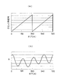
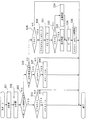
しかし、従来のクランク角検出手段の被検出部は、所定の角度ピッチごとに外周に凸状歯が形成される金属プレートである。このため、クランク角信号は、例えば、図6(a)に示すようにクランク角θの30°CAごとにパルス状に変化するので、角速度ωの計測値は、図6(b)に示すように30°CAごとの離散的な値になる。
[Deficiencies of conventional technology]
However, the detected portion of the conventional crank angle detecting means is a metal plate in which convex teeth are formed on the outer periphery at every predetermined angular pitch. For this reason, for example, as shown in FIG. 6A, the crank angle signal changes in a pulse shape every 30 ° CA of the crank angle θ, and the measured value of the angular velocity ω is as shown in FIG. 6B. It becomes a discrete value every 30 ° CA.
そこで、当該気筒燃焼時の角速度ωの最大値ωmaxおよび最小値ωminは、所定のクランク角θにおける角速度ωの計測値を当てはめることにより算出されている(例えば、特許文献1参照)。例えば、エンジンが4気筒の場合、最大値ωmaxは、クランク角θが30、210、390、570°CAにおける角速度ωの計測値であり、最小値ωminは、クランク角θが120、300、480、660°CAにおける角速度ωの計測値である。このため、最大値ωmaxや最小値ωminの算出値は、真値との誤差が大きいので、失火検出に対する信頼性が低い。 Therefore, the maximum value ωmax and the minimum value ωmin of the angular velocity ω during the combustion of the cylinder are calculated by applying the measured value of the angular velocity ω at a predetermined crank angle θ (see, for example, Patent Document 1). For example, when the engine has four cylinders, the maximum value ωmax is a measured value of the angular velocity ω when the crank angle θ is 30, 210, 390, and 570 ° CA, and the minimum value ωmin is 120, 300, and 480. , Measured value of angular velocity ω at 660 ° CA. For this reason, the calculated values of the maximum value ωmax and the minimum value ωmin have a large error from the true value, and thus the reliability for misfire detection is low.
さらに、金属プレートは外周の一部において、パルス数をカウントする基準位置を検出するために、凸状歯が形成されていない欠落部を有する。このため、欠落部に対応するクランク角θでは、クランク角信号が他のクランク角信号よりも遅れてパルス状に変化する(図6(a)参照)。このため、角速度ωの計測値は、欠落部に対応するクランク角θ(120°、480°)で急降下し、次に計測が行われるクランク角θ(150°、510°)で急上昇してしまう(図6(b)参照)。このため、欠落部の影響を受けるクランク角θでは、最大値ωmaxや最小値ωminの算出値と真値との誤差がさらに大きい。
本発明は、上記の問題点を解決するためになされたものであり、その目的は、回転変動量を求めるための角速度の最大値や最小値の算出値を、真値に近づけることにより、失火検出に対する信頼性を向上させることができる失火検出装置を提供することにある。 The present invention has been made in order to solve the above-described problems, and the purpose of the present invention is to make misfires by bringing the calculated values of the maximum and minimum angular velocities for obtaining the rotational fluctuation amount close to true values. An object of the present invention is to provide a misfire detection device capable of improving the reliability of detection.
〔請求項1の手段〕
請求項1に記載の失火検出装置は、角速度を計測するための信号を連続的に検出するクランク角検出手段と、少なくとも各気筒の燃焼行程の一部に対応するように設定される第1クランク角範囲と、第1クランク角範囲よりも遅れた範囲であって、燃焼行程の一部に対応するように設定される第2クランク角範囲と、当該気筒の第1クランク角範囲で計測された角速度の最大値と、当該気筒の第2クランク角範囲で計測された角速度の最小値との差を当該気筒の媒介変数として算出し、当該気筒の媒介変数に応じて、当該気筒で燃料の燃焼に異常が発生したか否かを判定する失火判定手段とを備える。
これにより、各気筒で燃料の燃焼が行われた時の角速度が最大になると予想されるクランク角を含むように第1クランク角範囲を設定し、各気筒で燃料の燃焼が行われた時の角速度が最小になると予想されるクランク角を含むように第2クランク角範囲を設定すれば、角速度の最大値および最小値を含むと予想される範囲で、角速度が連続的に計測される。この結果、角速度の最大値および最小値の算出値を、真値に近づけることができる。このため、当該気筒燃焼時の角速度の最大値と当該気筒燃焼時の角速度の最小値との差を媒介変数、すなわち回転変動量とする場合の失火検出に対する信頼性を向上させることができる。
[Means of Claim 1]
The misfire detection device according to
As a result, the first crank angle range is set so as to include the crank angle at which the angular velocity at which the fuel is burned in each cylinder is expected to be maximized, and when the fuel is burned in each cylinder. If the second crank angle range is set so as to include the crank angle at which the angular velocity is expected to be minimized, the angular velocity is continuously measured within the range expected to include the maximum value and the minimum value of the angular velocity. As a result, the calculated values of the maximum value and the minimum value of the angular velocity can be brought close to the true value. For this reason, it is possible to improve the reliability with respect to misfire detection when the difference between the maximum value of the angular velocity at the time of combustion of the cylinder and the minimum value of the angular velocity at the time of combustion of the cylinder is used as a parameter.
〔請求項2の手段〕
請求項2に記載の失火検出装置は、失火判定手段が、当該気筒の次以降に燃料の燃焼が行われる任意次気筒の第1クランク角範囲で計測された角速度の最大値と、任意次気筒の第2クランク角範囲で計測された角速度の最小値との差を任意次気筒の媒介変数として算出し、当該気筒の媒介変数と任意次気筒の媒介変数との差に応じて、当該気筒で燃料の燃焼に異常が発生したか否かを判定する。
これにより、失火判定に用いられる回転変動量の変化量として、回転変動量の気筒間の差を用いることができる。
[Means of claim 2]
The misfire detection device according to
Thereby, the difference between the rotation fluctuation amounts among the cylinders can be used as the change amount of the rotation fluctuation amount used for misfire determination.
〔請求項3の手段〕
請求項3に記載の失火検出装置は、失火判定手段が、任意次気筒の第1クランク角範囲で計測された角速度の最大値と、任意次気筒の第2クランク角範囲で計測された角速度の最小値との差を任意次気筒の媒介変数として算出し、当該気筒の媒介変数と任意次気筒の媒介変数との比に応じて、当該気筒で燃料の燃焼に異常が発生したか否かを判定する。
これにより、失火判定に用いられる回転変動量の変化量として、回転変動量の気筒間の比を用いることができる。ここで、回転変動量の算出に用いられる角速度は、エンジン回転数や負荷などのエンジンの状態に応じて変動するので、失火発生時の回転変動量も正常時の回転変動量も、エンジンの状態に応じて変動する。このため、失火判定の目安となる閾値を、エンジンの状態に応じて変更する必要がある。しかし、回転変動量の気筒間の比を算出すれば、エンジンの状態の影響を低減することができるので、閾値の変更幅を縮小することができる。
[Means of claim 3]
According to a third aspect of the present invention, in the misfire detection device, the misfire determination means includes a maximum value of the angular velocity measured in the first crank angle range of the arbitrary cylinder and an angular velocity measured in the second crank angle range of the arbitrary cylinder. The difference from the minimum value is calculated as a parameter for an arbitrary cylinder, and whether or not an abnormality has occurred in the combustion of fuel in that cylinder according to the ratio between the parameter for that cylinder and the parameter for the arbitrary cylinder. judge.
Thereby, the ratio of the rotation fluctuation amount between the cylinders can be used as the change amount of the rotation fluctuation amount used for the misfire determination. Here, since the angular velocity used to calculate the rotational fluctuation amount varies depending on the engine state such as the engine speed and load, both the rotational fluctuation amount at the time of misfiring and the rotational fluctuation amount at normal time are the engine state. Fluctuates depending on For this reason, it is necessary to change the threshold value used as a standard for misfire determination according to the state of the engine. However, if the ratio of the rotational fluctuation amount between the cylinders is calculated, the influence of the state of the engine can be reduced, so that the threshold change range can be reduced.
〔請求項4の手段〕
請求項4に記載の失火検出装置は、次気筒の第1クランク角範囲で計測された角速度の最大値と、当該気筒の第2クランク角範囲で計測された角速度の最小値との差を当該気筒の媒介変数として算出し、当該気筒の媒介変数に応じて、当該気筒で燃料の燃焼に異常が発生したか否かを判定する失火判定手段を備える。
これにより、次気筒燃焼時の角速度の最大値と当該気筒燃焼時の角速度の最小値との差を回転変動量とする場合の失火検出に対する信頼性を向上させることができる。
[Means of claim 4]
According to a fourth aspect of the present invention, there is provided a misfire detection device that calculates a difference between a maximum value of the angular velocity measured in the first crank angle range of the next cylinder and a minimum value of the angular velocity measured in the second crank angle range of the cylinder. A misfire determination means is provided for determining whether or not an abnormality has occurred in the combustion of fuel in the cylinder according to the parameter of the cylinder.
As a result, it is possible to improve the reliability with respect to misfire detection when the difference between the maximum value of the angular velocity during the next cylinder combustion and the minimum value of the angular velocity during the cylinder combustion is used as the rotation fluctuation amount.
〔請求項5の手段〕
請求項5に記載の失火検出装置は、失火判定手段が、次気筒の次以降に燃料の燃焼が行われる任意2次気筒の第1クランク角範囲で計測された角速度の最大値と、任意2次気筒の直前に燃料の燃焼が行われる任意次気筒の第2クランク角範囲で計測された角速度の最小値との差を任意次気筒の媒介変数として算出し、当該気筒の媒介変数と任意次気筒の媒介変数との差に応じて、当該気筒で燃料の燃焼に異常が発生したか否かを判定する。
これにより、失火判定に用いられる回転変動量の変化量として、回転変動量の気筒間の差を用いることができる。
[Means of claim 5]
In the misfire detection apparatus according to
Thereby, the difference between the rotation fluctuation amounts among the cylinders can be used as the change amount of the rotation fluctuation amount used for misfire determination.
〔請求項6の手段〕
請求項6に記載の失火検出装置は、失火判定手段が、任意2次気筒の第1クランク角範囲で計測された角速度の最大値と、任意次気筒の第2クランク角範囲で計測された角速度の最小値との差を任意次気筒の媒介変数として算出し、当該気筒の媒介変数と任意次気筒の媒介変数との比に応じて、当該気筒で燃料の燃焼に異常が発生したか否かを判定する。
これにより、失火判定に用いられる回転変動量の変化量として、回転変動量の気筒間の比を用いることができるとともに、失火判定の目安となる閾値の変更幅を縮小することができる。
[Means of claim 6]
The misfire detection device according to
As a result, the ratio of the rotation fluctuation amount between the cylinders can be used as the change amount of the rotation fluctuation amount used for the misfire determination, and the change range of the threshold value serving as a standard for the misfire determination can be reduced.
〔請求項7の手段〕
請求項7に記載の失火検出装置は、少なくとも各気筒の燃焼行程の一部に対応するように設定されるクランク角範囲、および当該気筒のクランク角範囲で計測された角速度の最大値を当該気筒の媒介変数とし、当該気筒の媒介変数に応じて、当該気筒で燃料の燃焼に異常が発生したか否かを判定する失火判定手段を備える。
これにより、当該気筒燃焼時の角速度の最大値を回転変動量とする場合の失火検出に対する信頼性を向上させることができる。
[Means of Claim 7]
The misfire detection device according to
Thereby, the reliability with respect to misfire detection when the maximum value of the angular velocity at the time of combustion of the cylinder is set as the rotation fluctuation amount can be improved.
〔請求項8の手段〕
請求項8に記載の失火検出装置は、失火判定手段が、当該気筒の次以降に燃料の燃焼が行われる任意次気筒のクランク角範囲で計測された角速度の最大値を任意次気筒の媒介変数とし、当該気筒の媒介変数と任意次気筒の媒介変数との差に応じて、当該気筒で燃料の燃焼に異常が発生したか否かを判定する。
これにより、失火判定に用いられる回転変動量の変化量として、回転変動量の気筒間の差を用いることができる。
[Means of Claim 8]
The misfire detection apparatus according to
Thereby, the difference between the rotation fluctuation amounts among the cylinders can be used as the change amount of the rotation fluctuation amount used for misfire determination.
〔請求項9の手段〕
請求項9に記載の失火検出装置は、失火判定手段が、任意次気筒のクランク角範囲で計測された角速度の最大値を任意次気筒の媒介変数とし、当該気筒の媒介変数と任意次気筒の媒介変数との比に応じて、当該気筒で燃料の燃焼に異常が発生したか否かを判定する。
これにより、失火判定に用いられる回転変動量の変化量として、回転変動量の気筒間の比を用いることができるとともに、失火判定の目安となる閾値の変更幅を縮小することができる。
[Means of Claim 9]
In the misfire detection device according to
As a result, the ratio of the rotation fluctuation amount between the cylinders can be used as the change amount of the rotation fluctuation amount used for the misfire determination, and the change range of the threshold value serving as a standard for the misfire determination can be reduced.
〔請求項10の手段〕
請求項10に記載の失火検出装置は、当該気筒のクランク角範囲で計測された角速度の最小値を当該気筒の媒介変数とし、当該気筒の媒介変数に応じて、当該気筒で燃料の燃焼に異常が発生したか否かを判定する失火判定手段を備える。
これにより、当該気筒燃焼時の角速度の最小値を回転変動量とする場合の失火検出に対する信頼性を向上させることができる。
[Means of Claim 10]
The misfire detection device according to
Thereby, the reliability with respect to misfire detection when the minimum value of the angular velocity at the time of combustion of the cylinder is set as the rotation fluctuation amount can be improved.
〔請求項11の手段〕
請求項11に記載の失火検出装置は、失火判定手段が、任意次気筒のクランク角範囲で計測された角速度の最小値を任意次気筒の媒介変数とし、当該気筒の媒介変数と任意次気筒の媒介変数との差に応じて、当該気筒で燃料の燃焼に異常が発生したか否かを判定する。
これにより、失火判定に用いられる回転変動量の変化量として、回転変動量の気筒間の差を用いることができる。
[Means of Claim 11]
In the misfire detection apparatus according to
Thereby, the difference between the rotation fluctuation amounts among the cylinders can be used as the change amount of the rotation fluctuation amount used for misfire determination.
〔請求項12の手段〕
請求項12に記載の失火検出装置は、失火判定手段が、任意次気筒のクランク角範囲で計測された角速度の最小値を任意次気筒の媒介変数とし、当該気筒の媒介変数と任意次気筒の媒介変数との比に応じて、当該気筒で燃料の燃焼に異常が発生したか否かを判定する。
これにより、失火判定に用いられる回転変動量の変化量として、回転変動量の気筒間の比を用いることができるとともに、失火判定の目安となる閾値の変更幅を縮小することができる。
[Means of Claim 12]
In the misfire detection apparatus according to
As a result, the ratio of the rotation fluctuation amount between the cylinders can be used as the change amount of the rotation fluctuation amount used for the misfire determination, and the change range of the threshold value serving as a standard for the misfire determination can be reduced.
最良の形態1の失火検出装置は、クランクシャフトの角速度を計測するための信号を連続的に検出するクランク角検出手段と、少なくとも各気筒の燃焼行程の一部に対応するように設定される第1クランク角範囲と、第1クランク角範囲よりも遅れた範囲であって、燃焼行程の一部に対応するように設定される第2クランク角範囲と、当該気筒の第1クランク角範囲で計測された角速度の最大値と、当該気筒の第2クランク角範囲で計測された角速度の最小値との差を当該気筒の媒介変数として算出し、当該気筒の媒介変数に応じて、当該気筒で燃料の燃焼に異常が発生したか否かを判定する失火判定手段とを備える。
さらに、失火判定手段は、当該気筒の次以降に燃料の燃焼が行われる任意次気筒の第1クランク角範囲で計測された角速度の最大値と、任意次気筒の第2クランク角範囲で計測された角速度の最小値との差を任意次気筒の媒介変数として算出し、当該気筒の媒介変数と任意次気筒の媒介変数との差に応じて、当該気筒で燃料の燃焼に異常が発生したか否かを判定する。
The misfire detection device of the
Further, the misfire determination means is measured in the maximum value of the angular velocity measured in the first crank angle range of the arbitrary cylinder in which fuel is burned after the cylinder and in the second crank angle range of the arbitrary cylinder. The difference between the measured value and the minimum value of the angular velocity is calculated as a parameter for the optional cylinder, and whether there is an abnormality in fuel combustion in the cylinder according to the difference between the parameter for the cylinder and the parameter for the optional cylinder Determine whether or not.
最良の形態2の失火検出装置は、失火判定手段が、任意次気筒の第1クランク角範囲で計測された角速度の最大値と、任意次気筒の第2クランク角範囲で計測された角速度の最小値との差を任意次気筒の媒介変数として算出し、当該気筒の媒介変数と任意次気筒の媒介変数との比に応じて、当該気筒で燃料の燃焼に異常が発生したか否かを判定する。
In the misfire detection device according to the
〔実施例1の構成〕
実施例1の失火検出装置1の構成を図1ないし図3に基づいて説明する。
失火検出装置1は、図1に示すごとく、クランク角θや角速度ωを計測するためのクランク角信号を連続的に検出するクランク角検出手段3と、クランク角信号やその他の検出手段から検出される電気信号が入力されるとともに失火検出等の各種の制御を実行する電子制御装置(ECU)5とを備える。
[Configuration of Example 1]
The configuration of the
As shown in FIG. 1, the
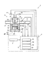
ここで、失火検出装置1を含むエンジン制御装置7を、図1を用いて説明する。エンジン制御装置7は、例えば4つの気筒#1〜#4を有するエンジン9と、クランク角検出手段3、スロットルセンサ11、エアフローメータ13および水温センサ15などの各種検出手段と、ECU5とを備える。
Here, the
エンジン9は、吸気管17から供給される燃料と空気との混合気を気筒#1〜#4の燃焼室19で爆発、燃焼させ、排気ガスを排気管21から排出させることにより、ピストン23を気筒#1〜#4内で直線往復動させるとともにクランクシャフト(図示せず)を回転させる周知構造である。
The
吸気管17には、燃焼室19に吸入される空気量を調節するスロットルバルブ25、および燃焼室19に吸入される空気に燃料を噴射供給するインジェクタ27が配置されている。
A
燃焼室19の上部には、燃焼室19に混合気を吸入するための吸気バルブ29、燃焼室19から排気ガスを排出するための排気バルブ31、混合気に着火することにより燃料の燃焼を開始させる点火プラグ33が配置されている。吸気、排気バルブ29、31は、各々、吸気側、排気側カム軸35、37により駆動されるとともに、吸気側、排気側可変バルブタイミング機構39、41により、開閉タイミングが調節されている。
In the upper part of the
気筒#1〜#4が形成されるシリンダブロック43には、冷却水が循環される冷却水路45が設けられ、ピストンリング47と気筒#1〜#4の内周壁との摺動により発生する熱が除去される。また、ピストン23とクランクシャフトとは、コンロッド49により連結されている。
The cylinder block 43 in which the
クランク角検出手段3は、クランク角信号を検出してECU5へ出力する。クランク角検出手段3は、クランクシャフトに取り付けられる被検出部(図示せず)と、被検出部の回転に合わせてクランク角信号を出力する検出部(図示せず)とを備えている。本実施例では、被検出部は、例えばクランクシャフトに取り付けられてクランクシャフトとともに回転する永久磁石(図示せず)を具備し、検出部は、例えば永久磁石の回転に伴い誘起される起電力が正弦曲線状に連続的に経時変化するコイル(図示せず)を具備する。
The crank angle detection means 3 detects a crank angle signal and outputs it to the
これにより、クランク角検出手段3は、例えば図2(a)に示すように、コイルに誘起される起電力を逆三角関数で変換することにより、クランク角θに対してリニアなクランク角信号を出力することができる。このため、例えば図2(b)に示すように、角速度ωを連続的な値として計測できる。 As a result, the crank angle detection means 3 converts the electromotive force induced in the coil with an inverse trigonometric function to generate a crank angle signal that is linear with respect to the crank angle θ, for example, as shown in FIG. Can be output. Therefore, for example, as shown in FIG. 2B, the angular velocity ω can be measured as a continuous value.
スロットルセンサ11は、図1に示すように、スロットルバルブ25の開度を計測するための電気信号を検出してECU5へ出力する。エアフローメータ13は、燃焼室19に吸入される空気量を計測するための電気信号を検出してECU5へ出力する。水温センサ15は、冷却水路45の冷却水温度を計測するための電気信号を検出してECU5へ出力する。
As shown in FIG. 1, the
ECU5は、制御処理、演算処理を行うCPU51、各種プログラムやデータを記憶するROM53、RAM55およびバックアップRAM57などの記憶装置、入力装置(図示せず)および出力装置(図示せず)などを有する。そして、ECU5は、クランク角検出手段3、スロットルセンサ11、エアフローメータ13および水温センサ15などの各種検出手段で検出された電気信号が入力され、これらの電気信号に応じてインジェクタ27、点火プラグ33、および吸気側、排気側可変バルブタイミング機構39、41などを駆動するための電気信号を出力する。以上により、ECU5は、エンジン9の点火時期制御や燃料噴射時期制御を実行する。
The
また、ECU5は、クランク角検出手段3から出力されるクランク角信号に応じて失火が発生したか否かを判定する失火判定手段としての機能を有する。また、ECU5は、失火判定をする際に用いる第1クランク角範囲a1、第2クランク角範囲a2を記憶する。
The
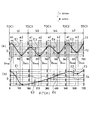
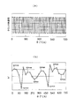
第1クランク角範囲a1は、図3に示すように燃焼行程b1〜b4の一部に対応するように設定される範囲である。ここで、燃焼行程b1〜b4とは、気筒#1〜#4の燃焼室19に供給された混合気が圧縮されて、ピストン23が気筒#1〜#4の各々の上死点TDC1〜TDC4に到達してから、燃料の燃焼が開始されてピストン23が気筒#1〜#4の各々の下死点に到達するまでの行程である。本実施例のエンジン9のように4つの気筒#1〜#4を有する場合、燃焼行程b1〜b4は、ほぼ、当該気筒#1〜#4のピストン23が上死点TDC1〜TDC4に到達してから、次気筒#1〜#4のピストン23が上死点TDC1〜TDC4に到達するまでの期間に相当する。第1クランク角範囲a1は、燃焼行程b1〜b4の各々で角速度ωが最大になると予想されるクランク角θmaxを含むように設定される。すなわち、第1クランク角範囲a1は、燃焼行程b1〜b4ごとに設定される。
The first crank angle range a1 is a range set to correspond to a part of the combustion strokes b1 to b4 as shown in FIG. Here, in the combustion strokes b1 to b4, the air-fuel mixture supplied to the
第2クランク角範囲a2は、図3に示すように第1クランク角範囲a1よりも遅れた範囲であって、燃焼行程b1〜b4の一部に対応するように設定される範囲である。第2クランク角範囲a2は、燃焼行程b1〜b4の各々で角速度ωが最小になると予想されるクランク角θminを含むように設定される。すなわち、第2クランク角範囲a2は、燃焼行程b1〜b4ごとに設定される。 As shown in FIG. 3, the second crank angle range a2 is a range that is delayed from the first crank angle range a1, and is a range that is set to correspond to a part of the combustion strokes b1 to b4. The second crank angle range a2 is set to include a crank angle θmin that is expected to minimize the angular velocity ω in each of the combustion strokes b1 to b4. That is, the second crank angle range a2 is set for each of the combustion strokes b1 to b4.
〔実施例1の失火検出方法〕
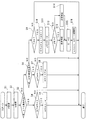
実施例1の失火検出装置1を用いた失火検出方法を、図4に示す失火検出フローに基づいて説明する。失火検出フローは、所定のプログラムとしてECU5に記憶されるとともに、ECU5により実行される。また、ECU5は、失火検出フローを実行することにより、失火判定手段として機能する。
[Misfire detection method of Example 1]
A misfire detection method using the
まず、ステップS1、S2で入力されたクランク角信号を用いてクランク角θおよび角速度ωが計測される。次に、ステップS3でクランク角θが当該気筒#1〜#4の第1クランク角範囲a1に含まれているか否かが判定され、含まれていると判定された場合(YES)にはステップS4、S5で角速度ωの最大値ωmaxが算出される。すなわち、ステップS4で角速度ωの計測値が現在の最大値ωmaxよりも大きいか否かが判定される。そして、角速度ωの計測値が現在の最大値ωmaxよりも大きいと判定された場合(YES)、ステップS5で最大値ωmaxを角速度ωの計測値に置き換える。
First, the crank angle θ and the angular velocity ω are measured using the crank angle signal input in steps S1 and S2. Next, it is determined whether or not the crank angle θ is included in the first crank angle range a1 of the
次に、ステップS3でクランク角θが当該気筒#1〜#4の第1クランク角範囲a1に含まれていないと判定された場合(NO)、ステップS6でクランク角θが当該気筒#1〜#4の第2クランク角範囲a2に含まれているか否かが判定される。含まれていると判定された場合(YES)、ステップS7、S8で角速度ωの最小値ωminが算出される。すなわち、ステップS7で角速度ωの計測値が現在の最小値ωminよりも小さいか否かが判定される。そして、角速度ωの計測値が現在の最小値ωminよりも小さいと判定された場合(YES)、ステップS8で最小値ωminを角速度ωの計測値に置き換える。
Next, when it is determined in step S3 that the crank angle θ is not included in the first crank angle range a1 of the
次に、ステップS6でクランク角θが当該気筒#1〜#4の第2クランク角範囲a2に含まれていないと判定された場合(NO)、ステップS9で次気筒#1〜#4のピストン23が上死点TDC1〜TDC4にあるか否かが判定される。上死点TDC1〜TDC4にあると判定された場合(YES)、ステップS10〜S12で、当該気筒#1〜#4で失火が発生したか否かの判定が行われる。すなわち、ステップS10で最大値ωmaxと最小値ωminとの差、すなわち回転変動量Eが算出される。次に、ステップS11で現在の回転変動量Eと、前回の失火検出フローで算出された回転変動量(以下、直近値と呼ぶ)E′との差ΔEが算出される。そして、ステップS12で差ΔEが所定値Cよりも大きいと判定された場合(YES)、ステップS13へ進み失火が発生したと判定される。また、ステップS12で差ΔEが所定値Cよりも小さいと判定された場合(NO)、ステップS14へ進み、燃料の燃焼が正常に行われたと判定される。
Next, when it is determined in step S6 that the crank angle θ is not included in the second crank angle range a2 of the
そして、ステップS15で直近値E′を現在の回転変動量Eに置き換え、ステップS16で角速度ωの最大値ωmaxおよび最小値ωminを初期値に置き換えた後、失火検出フローを終了する。 In step S15, the latest value E ′ is replaced with the current rotational fluctuation amount E. In step S16, the maximum value ωmax and the minimum value ωmin of the angular velocity ω are replaced with initial values, and then the misfire detection flow is terminated.
〔実施例1の作用〕
実施例1の失火検出装置1の作用を説明する。
失火検出装置1は、失火検出フローを実行することにより、図3に示すごとく、各々の燃焼行程b1〜b4において、第1クランク角範囲a1で最大値ωmaxが算出され、第2クランク角範囲a2で最小値ωminが算出される。また、各気筒#1〜#4のピストン23が上死点TDC1〜TDC4に到達するたびに、回転変動量Eおよび差ΔEが算出される。
[Operation of Example 1]
The operation of the
As shown in FIG. 3, the
図3(a)では、エンジン9が高回転かつ低負荷の状態で作動している場合の角速度ωの経時変化が示されている。ここで、トレンドT1は、気筒#1の燃焼行程b1で失火が発生した異常時の角速度ωの経時変化であり、トレンドT2は、失火が発生しない正常時の角速度ωの経時変化である。
FIG. 3A shows the change over time of the angular velocity ω when the
燃焼行程b1で失火が発生すると、回転変動量Eの燃焼行程b1における値E1と燃焼行程b3における値E3との差ΔEは所定値Cよりも大きくなる。そして、気筒#3のピストン23が上死点TDC3に到達したときに、気筒#1で失火が発生したと判定される。燃焼行程b3における値E3と燃焼行程b4における値E4との差ΔE、燃焼行程b4における値E4と燃焼行程b2における値E2との差ΔE、および燃焼行程b2における値E2と燃焼行程b1における値E1との差ΔEは、所定値Cよりも小さい。このため、気筒#4、#2、#1のピストン23が上死点TDC4、TDC2、TDC1に到達したときに、気筒#3、#4、#2で燃料の燃焼が正常に行われたと判定される。
When misfire occurs in the combustion stroke b1, the difference ΔE between the value E1 in the combustion stroke b1 and the value E3 in the combustion stroke b3 of the rotational fluctuation amount E becomes larger than the predetermined value C. Then, when the
図3(b)では、エンジン9が高負荷の状態で作動している場合の角速度ωの経時変化が示されている。ここで、トレンドT3は、気筒#1の燃焼行程b1で失火が発生した異常時の角速度ωの経時変化であり、トレンドT4は、失火が発生しない正常時の角速度ωの経時変化である。
FIG. 3B shows a change with time of the angular velocity ω when the
燃焼行程b1で失火が発生すると、回転変動量Eの燃焼行程b1における値E1と燃焼行程b3における値E3との差ΔEは所定値Cよりも大きくなる。そして、気筒#3のピストン23が上死点TDC3に到達したときに、気筒#1で失火が発生したと判定される。燃焼行程b3における値E3と燃焼行程b4における値E4との差ΔE、燃焼行程b4における値E4と燃焼行程b2における値E2との差ΔE、および燃焼行程b2における値E2と燃焼行程b1における値E1との差ΔEは、所定値Cよりも小さい。このため、気筒#4、#2、#1のピストン23が上死点TDC4、TDC2、TDC1に到達したときに、気筒#3、#4、#2で燃料の燃焼が正常に行われたと判定される。なお、燃焼行程b3、b4では、最小値ωminの方が最大値ωmaxよりも大きいため、値E3、E4は負の値として算出される。
When misfire occurs in the combustion stroke b1, the difference ΔE between the value E1 in the combustion stroke b1 and the value E3 in the combustion stroke b3 of the rotational fluctuation amount E becomes larger than the predetermined value C. Then, when the
このように、実施例1の失火検出装置1は、当該気筒#1〜#4の回転変動量Eと次気筒#1〜#4の回転変動量Eとの差ΔEに応じて、当該気筒#1〜#4で失火が発生したか否かの判定を行う。すなわち、実施例1の失火検出装置1は、当該気筒#1〜#4の次以降に燃料の燃焼が行われる任意次気筒#1〜#4の回転変動量Eの中から、次気筒#1〜#4の回転変動量Eを、差ΔEを求めるための媒介変数として用いている。より具体的に説明すると、実施例1では、例えば気筒#1で失火が発生したか否かの判定を行う場合、気筒#1の次以降に燃料の噴射が行われる気筒#3、#4、#2、#1(以降、#3、#4、#2、#1が繰り返される)の中から、気筒#1の次に燃料の噴射が行われる気筒#3の回転変動量E3を、差ΔEを求めるための媒介変数として用いている。
As described above, the
〔実施例1の効果〕
実施例1の失火検出装置1によれば、第1クランク角範囲a1は、燃焼行程b1〜b4の各々で角速度ωが最大になると予想されるクランク角θmaxを含むように設定され、第2クランク角範囲a2は、燃焼行程b1〜b4の各々で角速度ωが最小になると予想されるクランク角θminを含むように設定される。そして、連続的に計測されたクランク角θおよび角速度ωを用いて、当該気筒#1〜#4の第1クランク角範囲a1で最大値ωmaxが算出され、当該気筒#1〜#4の第2クランク角範囲a2で最小値ωminが算出される。そして、最大値ωmaxと最小値ωminとの差を回転変動量Eとし、この回転変動量Eに基づいて失火が発生したか否かの判定が行われる。
これにより、最大値ωmaxおよび最小値ωminの算出値を、真値に近づけることができるので、失火検出に対する信頼性を向上させることができる。なお、失火検出装置1を用いれば、点火時期制御などの実行に伴い燃料の燃焼開始時期が遅角したり進角したりしても、最大値ωmaxおよび最小値ωminの算出値を、真値に近づけることができる。さらに、突発的な角速度ωの変動が生じても、最大値ωmaxおよび最小値ωminの算出値を、真値に近づけることができる。
[Effect of Example 1]
According to the
Thereby, since the calculated values of the maximum value ωmax and the minimum value ωmin can be brought close to the true value, the reliability with respect to misfire detection can be improved. If the
また、クランク角検出手段3は、クランク角θに対して、リニアなクランク角信号を出力することができる。
これにより、パルス数をカウントする基準位置を検出する必要がなくなるので、従来のような基準位置の検出に伴う角速度ωの計測値の大幅変動が発生しない。このため、すべてのクランク角θで、最大値ωmaxや最小値ωminの算出値を、真値に近づけることができる。
Further, the crank angle detection means 3 can output a linear crank angle signal with respect to the crank angle θ.
This eliminates the need to detect the reference position for counting the number of pulses, so that there is no significant variation in the measured value of the angular velocity ω that accompanies the detection of the reference position as in the prior art. Therefore, the calculated values of the maximum value ωmax and the minimum value ωmin can be made close to the true value at all crank angles θ.
また、最大値ωmaxの算出は第1クランク角範囲a1においてのみ行われ、最小値ωminの算出は、第2クランク角範囲a2においてのみ行われる。
これにより、第1、第2クランク角範囲a1、a2を狭くするほど、ECU5の演算負荷を低減することができる。
The maximum value ωmax is calculated only in the first crank angle range a1, and the minimum value ωmin is calculated only in the second crank angle range a2.
Thereby, the calculation load of ECU5 can be reduced, so that 1st, 2nd crank angle range a1, a2 is narrowed.
〔実施例2の失火検出方法〕
実施例2の失火検出フローでは、当該気筒#1〜#4で失火が発生したか否かの判定を行う際に、直近値E′と現在の回転変動量Eとの比δEを算出する。そして、失火検出フローは、比δEに応じて、当該気筒#1〜#4で失火が発生したか否かの判定を行う。すなわち、図5に示すように、ステップS31で直近値E′と、現在の回転変動量Eとの比δEが算出される。そして、ステップS32で比δEが所定値C2よりも大きいと判定された場合(YES)、ステップS33へ進み失火が発生したと判定される。また、ステップS32で比δEが所定値C2よりも小さいと判定された場合(NO)、ステップS34へ進み、燃料の燃焼が正常に行われたと判定される。なお、図5のステップS21〜S30、およびステップS35、S36は、図4のステップS1〜S10、およびステップS15、S16に相当する。
[Misfire detection method of embodiment 2]
In the misfire detection flow of the second embodiment, when determining whether or not misfire has occurred in the
〔実施例2の効果〕
実施例2の失火検出装置1は、直近値E′と現在の回転変動量Eとの比δEを算出し、この比δEに応じて、当該気筒#1〜#4で失火が発生したか否かの判定を行う。
これにより、失火判定に用いられる回転変動量Eの変化量として、回転変動量Eの気筒間の比δEを用いることができる。ここで、回転変動量Eの算出に用いられる角速度ωは、エンジン回転数や負荷などのエンジン9の状態に応じて変動するので、失火発生時の回転変動量Eも正常時の回転変動量Eも、エンジン9の状態に応じて変動する。このため、失火判定の目安となる閾値を、エンジン9の状態に応じて変更する必要がある。しかし、回転変動量Eの気筒間の比δEを算出すれば、エンジン9の状態の影響を低減することができるので、閾値(すなわち、所定値C2)の変更幅を縮小することができる。
[Effect of Example 2]
The
Thereby, the ratio δE between the cylinders of the rotation fluctuation amount E can be used as the change amount of the rotation fluctuation amount E used for misfire determination. Here, since the angular velocity ω used for calculation of the rotational fluctuation amount E varies depending on the state of the
〔変形例〕
本実施例では、当該気筒#1〜#4の第1クランク角範囲a1で計測された角速度ωの最大値ωmaxと、当該気筒#1〜#4の第2クランク角範囲a2で計測された角速度ωの最小値ωminとの差を回転変動量Eとして算出し、この回転変動量Eに応じて失火検出を行ったが、次気筒#1〜#4の第1クランク角範囲a1で求められる最大値ωmaxと、当該気筒#1〜#4の第2クランク角範囲a2で求められる最小値ωminとの差を回転変動量Eとして算出し、この回転変動量Eに応じて失火検出を行ってもよい。
また、当該気筒#1〜#4の第1クランク角範囲a1で求められる最大値ωmaxを回転変動量Eとし、この回転変動量Eに応じて失火検出を行ってもよい。さらに、当該気筒#1〜#4の第2クランク角範囲a2で求められる最小値ωminを回転変動量Eとし、この回転変動量Eに応じて失火検出を行ってもよい。
[Modification]
In the present embodiment, the maximum value ωmax of the angular velocity ω measured in the first crank angle range a1 of the
Further, the maximum value ωmax obtained in the first crank angle range a1 of the
本実施例では、任意次気筒#1〜#4の回転変動量Eの中から、次気筒#1〜#4の回転変動量Eを、差ΔEまたは比δEを求めるための媒介変数として選択して用いたが、次気筒の次以降に燃料の噴射が行われる任意2次気筒#1〜#4の回転変動量Eを選択して用いてもよい。例えば気筒#1で失火が発生したか否かの判定を行う場合、気筒#1の次の気筒#3よりも後に燃料の噴射が行われる気筒#4、#2、#1(以降、#3、#4、#2、#1が繰り返される)の中から、差ΔEまたは比δEを求めるための媒介変数を選択してもよい。すなわち、差ΔEまたは比δEを求めるための媒介変数を、当該気筒#1〜#4のエンジンサイクルよりも後のエンジンサイクルにおける任意次気筒(または任意2次気筒)#1〜#4の回転変動量Eの中から選択してもよい。
In this embodiment, the rotational fluctuation amount E of the
本実施例では、当該気筒#1〜#4の第1、第2クランク角範囲a1、a2は、当該気筒#1〜#4の燃焼行程b1〜b4に納まるように設定されたが、例えば、第1クランク角範囲a1が、当該気筒#1〜#4の前に燃料の燃焼が行われる気筒#1〜#4の燃焼行程b1〜b4にまたがるように設定されてもよい。また、第2クランク角範囲a2が、次気筒#1〜#4の燃焼行程b1〜b4にまたがるように設定されてもよい。
In the present embodiment, the first and second crank angle ranges a1 and a2 of the
本実施例では、クランク角θが第1、第2クランク角範囲a1、a2に含まれるか否かを判定する前に角速度ωを計測したが、クランク角θが第1、第2クランク角範囲a1、a2に含まれるか否かを判定した後に角速度ωを計測してもよい。これにより、ECU5による角速度ωの計測回数が減るので、ECU5の演算負荷を低減できる。 In this embodiment, the angular velocity ω is measured before determining whether or not the crank angle θ is included in the first and second crank angle ranges a1 and a2. However, the crank angle θ is measured in the first and second crank angle ranges. The angular velocity ω may be measured after determining whether or not included in a1 and a2. Thereby, since the frequency | count of measurement of angular velocity (omega) by ECU5 reduces, the calculation load of ECU5 can be reduced.
1 失火検出装置
3 クランク角検出手段
5 ECU(失火判定手段)
9 エンジン
#1〜#4 気筒
ω 角速度
ωmax 最大値
ωmin 最小値
a1 第1クランク角範囲(クランク角範囲)
a2 第2クランク角範囲(クランク角範囲)
b1〜b4 燃焼行程
E 回転変動量(媒介変数)
DESCRIPTION OF
9
a2 Second crank angle range (crank angle range)
b1 to b4 Combustion stroke E Rotational fluctuation amount (parameter)
Claims (12)
クランクシャフトの角速度を計測するための信号を連続的に検出するクランク角検出手段と、
少なくとも各気筒の燃焼行程の一部に対応するように設定される第1クランク角範囲と、
この第1クランク角範囲よりも遅れた範囲であって、前記燃焼行程の一部に対応するように設定される第2クランク角範囲と、
前記気筒の前記第1クランク角範囲で計測された前記角速度の最大値と、前記気筒の前記第2クランク角範囲で計測された前記角速度の最小値との差を前記気筒の媒介変数として算出し、前記気筒の媒介変数に応じて、前記気筒で燃料の燃焼に異常が発生したか否かを判定する失火判定手段と
を備える失火検出装置。 A misfire detection device that detects whether an abnormality has occurred in the combustion of fuel in a cylinder of an engine,
Crank angle detecting means for continuously detecting a signal for measuring the angular velocity of the crankshaft;
A first crank angle range set to correspond to at least a part of the combustion stroke of each cylinder;
A second crank angle range set to correspond to a part of the combustion stroke, which is a range delayed from the first crank angle range;
A difference between the maximum value of the angular velocity measured in the first crank angle range of the cylinder and the minimum value of the angular velocity measured in the second crank angle range of the cylinder is calculated as a parameter of the cylinder. A misfire detection device comprising misfire determination means for determining whether or not an abnormality has occurred in fuel combustion in the cylinder according to a parameter of the cylinder.
前記失火判定手段は、
前記気筒の次以降に燃料の燃焼が行われる任意次気筒の前記第1クランク角範囲で計測された前記角速度の最大値と、前記任意次気筒の前記第2クランク角範囲で計測された前記角速度の最小値との差を前記任意次気筒の媒介変数として算出し、
前記気筒の媒介変数と前記任意次気筒の媒介変数との差に応じて、前記気筒で燃料の燃焼に異常が発生したか否かを判定すること
を特徴とする失火検出装置。 The misfire detection device according to claim 1,
The misfire determination means includes
The maximum value of the angular velocity measured in the first crank angle range of an arbitrary cylinder in which fuel is burned after the cylinder and the angular velocity measured in the second crank angle range of the arbitrary cylinder. The difference from the minimum value of is calculated as a parameter of the arbitrary cylinder,
A misfire detection apparatus that determines whether or not an abnormality has occurred in the combustion of fuel in the cylinder according to a difference between a parameter of the cylinder and a parameter of the arbitrary cylinder.
前記失火判定手段は、
前記気筒の次以降に燃料の燃焼が行われる任意次気筒の前記第1クランク角範囲で計測された前記角速度の最大値と、前記任意次気筒の前記第2クランク角範囲で計測された前記角速度の最小値との差を前記任意次気筒の媒介変数として算出し、
前記気筒の媒介変数と前記任意次気筒の媒介変数との比に応じて、前記気筒で燃料の燃焼に異常が発生したか否かを判定すること
を特徴とする失火検出装置。 The misfire detection device according to claim 1,
The misfire determination means includes
The maximum value of the angular velocity measured in the first crank angle range of an arbitrary cylinder in which fuel is burned after the cylinder and the angular velocity measured in the second crank angle range of the arbitrary cylinder. The difference from the minimum value of is calculated as a parameter of the arbitrary cylinder,
A misfire detection apparatus that determines whether or not an abnormality has occurred in fuel combustion in the cylinder according to a ratio between a parameter of the cylinder and a parameter of the arbitrary cylinder.
クランクシャフトの角速度を計測するための信号を連続的に検出するクランク角検出手段と、
少なくとも各気筒の燃焼行程の一部に対応するように設定される第1クランク角範囲と、
この第1クランク角範囲よりも遅れた範囲であって、前記燃焼行程の一部に対応するように設定される第2クランク角範囲と、
前記気筒の次に燃料の燃焼が行われる次気筒の前記第1クランク角範囲で計測された前記角速度の最大値と、前記気筒の前記第2クランク角範囲で計測された前記角速度の最小値との差を前記気筒の媒介変数として算出し、前記気筒の媒介変数に応じて、前記気筒で燃料の燃焼に異常が発生したか否かを判定する失火判定手段と
を備える失火検出装置。 A misfire detection device that detects whether an abnormality has occurred in the combustion of fuel in a cylinder of an engine,
Crank angle detecting means for continuously detecting a signal for measuring the angular velocity of the crankshaft;
A first crank angle range set to correspond to at least a part of the combustion stroke of each cylinder;
A second crank angle range set to correspond to a part of the combustion stroke, which is a range delayed from the first crank angle range;
A maximum value of the angular velocity measured in the first crank angle range of a next cylinder in which fuel is burned next to the cylinder, and a minimum value of the angular velocity measured in the second crank angle range of the cylinder; A misfire detection device comprising: a misfire determination unit that calculates the difference between the cylinders as a parameter of the cylinder and determines whether an abnormality has occurred in fuel combustion in the cylinder according to the parameter of the cylinder.
前記失火判定手段は、
前記次気筒の次以降に燃料の燃焼が行われる任意2次気筒の前記第1クランク角範囲で計測された前記角速度の最大値と、前記任意2次気筒の直前に燃料の燃焼が行われる任意次気筒の前記第2クランク角範囲で計測された前記角速度の最小値との差を前記任意次気筒の媒介変数として算出し、
前記気筒の媒介変数と前記任意次気筒の媒介変数との差に応じて、前記気筒で燃料の燃焼に異常が発生したか否かを判定すること
を特徴とする失火検出装置。 The misfire detection device according to claim 4,
The misfire determination means includes
The maximum value of the angular velocity measured in the first crank angle range of an arbitrary secondary cylinder in which fuel is burned after the next cylinder and the fuel in which fuel is burned immediately before the arbitrary secondary cylinder Calculating a difference from the minimum value of the angular velocity measured in the second crank angle range of the next cylinder as a parameter of the arbitrary next cylinder;
A misfire detection apparatus that determines whether or not an abnormality has occurred in the combustion of fuel in the cylinder according to a difference between a parameter of the cylinder and a parameter of the arbitrary cylinder.
前記失火判定手段は、
前記次気筒の次以降に燃料の燃焼が行われる任意2次気筒の前記第1クランク角範囲で計測された前記角速度の最大値と、前記任意2次気筒の直前に燃料の燃焼が行われる任意次気筒の前記第2クランク角範囲で計測された前記角速度の最小値との差を前記任意次気筒の媒介変数として算出し、
前記気筒の媒介変数と前記任意次気筒の媒介変数との比に応じて、前記気筒で燃料の燃焼に異常が発生したか否かを判定すること
を特徴とする失火検出装置。 The misfire detection device according to claim 4,
The misfire determination means includes
The maximum value of the angular velocity measured in the first crank angle range of an arbitrary secondary cylinder in which fuel is burned after the next cylinder and the fuel in which fuel is burned immediately before the arbitrary secondary cylinder Calculating a difference from the minimum value of the angular velocity measured in the second crank angle range of the next cylinder as a parameter of the arbitrary next cylinder;
A misfire detection apparatus that determines whether or not an abnormality has occurred in fuel combustion in the cylinder according to a ratio between a parameter of the cylinder and a parameter of the arbitrary cylinder.
クランクシャフトの角速度を計測するための信号を連続的に検出するクランク角検出手段と、
少なくとも各気筒の燃焼行程の一部に対応するように設定されるクランク角範囲と、
前記気筒の前記クランク角範囲で計測された前記角速度の最大値を前記気筒の媒介変数とし、前記気筒の媒介変数に応じて、前記気筒で燃料の燃焼に異常が発生したか否かを判定する失火判定手段と
を備える失火検出装置。 A misfire detection device that detects whether an abnormality has occurred in the combustion of fuel in a cylinder of an engine,
Crank angle detecting means for continuously detecting a signal for measuring the angular velocity of the crankshaft;
A crank angle range set to correspond to at least a part of the combustion stroke of each cylinder;
The maximum value of the angular velocity measured in the crank angle range of the cylinder is used as a parameter of the cylinder, and it is determined whether an abnormality has occurred in fuel combustion in the cylinder according to the parameter of the cylinder. A misfire detection device comprising misfire determination means.
前記失火判定手段は、
前記気筒の次以降に燃料の燃焼が行われる任意次気筒の前記クランク角範囲で計測された前記角速度の最大値を前記任意次気筒の媒介変数とし、
前記気筒の媒介変数と前記任意次気筒の媒介変数との差に応じて、前記気筒で燃料の燃焼に異常が発生したか否かを判定すること
を特徴とする失火検出装置。 The misfire detection device according to claim 7,
The misfire determination means includes
The maximum value of the angular velocity measured in the crank angle range of an arbitrary cylinder where fuel is burned after the cylinder is used as a parameter of the arbitrary cylinder,
A misfire detection apparatus that determines whether or not an abnormality has occurred in the combustion of fuel in the cylinder according to a difference between a parameter of the cylinder and a parameter of the arbitrary cylinder.
前記失火判定手段は、
前記気筒の次以降に燃料の燃焼が行われる任意次気筒の前記クランク角範囲で計測された前記角速度の最大値を前記任意次気筒の媒介変数とし、
前記気筒の媒介変数と前記任意次気筒の媒介変数との比に応じて、前記気筒で燃料の燃焼に異常が発生したか否かを判定すること
を特徴とする失火検出装置。 The misfire detection device according to claim 7,
The misfire determination means includes
The maximum value of the angular velocity measured in the crank angle range of an arbitrary cylinder where fuel is burned after the cylinder is used as a parameter of the arbitrary cylinder,
A misfire detection apparatus that determines whether or not an abnormality has occurred in fuel combustion in the cylinder according to a ratio between a parameter of the cylinder and a parameter of the arbitrary cylinder.
クランクシャフトの角速度を計測するための信号を連続的に検出するクランク角検出手段と、
少なくとも各気筒の燃焼行程の一部に対応するように設定されるクランク角範囲と、
前記気筒の前記クランク角範囲で計測された前記角速度の最小値を前記気筒の媒介変数とし、前記気筒の媒介変数に応じて、前記気筒で燃料の燃焼に異常が発生したか否かを判定する失火判定手段と
を備える失火検出装置。 A misfire detection device that detects whether an abnormality has occurred in the combustion of fuel in a cylinder of an engine,
Crank angle detecting means for continuously detecting a signal for measuring the angular velocity of the crankshaft;
A crank angle range set to correspond to at least a part of the combustion stroke of each cylinder;
The minimum value of the angular velocity measured in the crank angle range of the cylinder is used as a parameter of the cylinder, and it is determined whether an abnormality has occurred in fuel combustion in the cylinder according to the parameter of the cylinder. A misfire detection device comprising misfire determination means.
前記失火判定手段は、
前記気筒の次以降に燃料の燃焼が行われる任意次気筒の前記クランク角範囲で計測された前記角速度の最小値を前記任意次気筒の媒介変数とし、
前記気筒の媒介変数と前記任意次気筒の媒介変数との差に応じて、前記気筒で燃料の燃焼に異常が発生したか否かを判定すること
を特徴とする失火検出装置。 The misfire detection device according to claim 10,
The misfire determination means includes
The minimum value of the angular velocity measured in the crank angle range of an arbitrary cylinder in which fuel is burned after the cylinder is used as a parameter of the arbitrary cylinder,
A misfire detection apparatus that determines whether or not an abnormality has occurred in the combustion of fuel in the cylinder according to a difference between a parameter of the cylinder and a parameter of the arbitrary cylinder.
前記失火判定手段は、
前記気筒の次以降に燃料の燃焼が行われる任意次気筒の前記クランク角範囲で計測された前記角速度の最小値を前記任意次気筒の媒介変数とし、
前記気筒の媒介変数と前記任意次気筒の媒介変数との比に応じて、前記気筒で燃料の燃焼に異常が発生したか否かを判定すること
を特徴とする失火検出装置。 The misfire detection device according to claim 10,
The misfire determination means includes
The minimum value of the angular velocity measured in the crank angle range of an arbitrary cylinder in which fuel is burned after the cylinder is used as a parameter of the arbitrary cylinder,
A misfire detection apparatus that determines whether or not an abnormality has occurred in fuel combustion in the cylinder according to a ratio between a parameter of the cylinder and a parameter of the arbitrary cylinder.
Priority Applications (3)
| Application Number | Priority Date | Filing Date | Title |
|---|---|---|---|
| JP2004111371A JP2005291182A (en) | 2004-04-05 | 2004-04-05 | Misfire detection device |
| US11/097,318 US7197916B2 (en) | 2004-04-05 | 2005-04-04 | Misfire detector using linear detection of crankshaft angular speed |
| DE102005015427A DE102005015427A1 (en) | 2004-04-05 | 2005-04-04 | Misfire detector |
Applications Claiming Priority (1)
| Application Number | Priority Date | Filing Date | Title |
|---|---|---|---|
| JP2004111371A JP2005291182A (en) | 2004-04-05 | 2004-04-05 | Misfire detection device |
Publications (1)
| Publication Number | Publication Date |
|---|---|
| JP2005291182A true JP2005291182A (en) | 2005-10-20 |
Family
ID=35034306
Family Applications (1)
| Application Number | Title | Priority Date | Filing Date |
|---|---|---|---|
| JP2004111371A Pending JP2005291182A (en) | 2004-04-05 | 2004-04-05 | Misfire detection device |
Country Status (3)
| Country | Link |
|---|---|
| US (1) | US7197916B2 (en) |
| JP (1) | JP2005291182A (en) |
| DE (1) | DE102005015427A1 (en) |
Cited By (1)
| Publication number | Priority date | Publication date | Assignee | Title |
|---|---|---|---|---|
| JP2014047628A (en) * | 2012-08-29 | 2014-03-17 | Daihatsu Motor Co Ltd | Control device of internal combustion engine |
Families Citing this family (22)
| Publication number | Priority date | Publication date | Assignee | Title |
|---|---|---|---|---|
| US10338580B2 (en) | 2014-10-22 | 2019-07-02 | Ge Global Sourcing Llc | System and method for determining vehicle orientation in a vehicle consist |
| US10464579B2 (en) | 2006-04-17 | 2019-11-05 | Ge Global Sourcing Llc | System and method for automated establishment of a vehicle consist |
| JP2009121303A (en) * | 2007-11-14 | 2009-06-04 | Denso Corp | Misfire detecting apparatus for internal combustion engine |
| JP4656169B2 (en) * | 2008-03-11 | 2011-03-23 | 日産自動車株式会社 | Engine misfire diagnostic device and misfire diagnostic method |
| JP5488286B2 (en) * | 2010-07-15 | 2014-05-14 | トヨタ自動車株式会社 | Combustion state detection system for internal combustion engine |
| US9845752B2 (en) | 2010-09-29 | 2017-12-19 | GM Global Technology Operations LLC | Systems and methods for determining crankshaft position based indicated mean effective pressure (IMEP) |
| US9127604B2 (en) | 2011-08-23 | 2015-09-08 | Richard Stephen Davis | Control system and method for preventing stochastic pre-ignition in an engine |
| US9097196B2 (en) * | 2011-08-31 | 2015-08-04 | GM Global Technology Operations LLC | Stochastic pre-ignition detection systems and methods |
| US8984930B2 (en) | 2011-09-15 | 2015-03-24 | General Electric Company | System and method for diagnosing a reciprocating compressor |
| US9046050B2 (en) | 2011-09-15 | 2015-06-02 | General Electric Company | Shaft imbalance detection system |
| US9897082B2 (en) | 2011-09-15 | 2018-02-20 | General Electric Company | Air compressor prognostic system |
| US10036335B2 (en) | 2011-09-15 | 2018-07-31 | General Electric Company | Systems and methods for diagnosing an engine |
| US8875561B2 (en) | 2011-09-15 | 2014-11-04 | General Electric Company | Systems and methods for diagnosing an engine |
| US20130280095A1 (en) | 2012-04-20 | 2013-10-24 | General Electric Company | Method and system for reciprocating compressor starting |
| US9121362B2 (en) | 2012-08-21 | 2015-09-01 | Brian E. Betz | Valvetrain fault indication systems and methods using knock sensing |
| US9133775B2 (en) | 2012-08-21 | 2015-09-15 | Brian E. Betz | Valvetrain fault indication systems and methods using engine misfire |
| US9606022B2 (en) | 2012-08-31 | 2017-03-28 | General Electric Company | Systems and methods for diagnosing engine components and auxiliary equipment associated with an engine |
| US8973429B2 (en) | 2013-02-25 | 2015-03-10 | GM Global Technology Operations LLC | System and method for detecting stochastic pre-ignition |
| US9574965B2 (en) | 2014-06-24 | 2017-02-21 | General Electric Company | System and method of determining bearing health in a rotating machine |
| US9732722B1 (en) * | 2015-03-06 | 2017-08-15 | Brunswick Corporation | Methods and systems for cylinder speed increase control to improve combustion uniformity |
| US10731582B2 (en) * | 2016-11-16 | 2020-08-04 | GM Global Technology Operations LLC | Determination of engine parameter based on determining a metric over three or more cylinder combustion cycles |
| JP7420053B2 (en) * | 2020-11-09 | 2024-01-23 | トヨタ自動車株式会社 | Internal combustion engine misfire detection device |
Citations (3)
| Publication number | Priority date | Publication date | Assignee | Title |
|---|---|---|---|---|
| JPH0422763A (en) * | 1990-05-15 | 1992-01-27 | Nippondenso Co Ltd | Misfire detecting device for internal combustion engine |
| JPH10231749A (en) * | 1996-12-19 | 1998-09-02 | Toyota Motor Corp | Control device for internal combustion engine |
| JPH11200915A (en) * | 1998-01-08 | 1999-07-27 | Yanmar Diesel Engine Co Ltd | Combustion control method of gas engine |
Family Cites Families (7)
| Publication number | Priority date | Publication date | Assignee | Title |
|---|---|---|---|---|
| JPH04265447A (en) * | 1991-02-19 | 1992-09-21 | Toyota Motor Corp | Misfired cylinder discriminating device for multi-cylinder internal combustion engine |
| US5309756A (en) * | 1991-07-04 | 1994-05-10 | Toyota Jidosha Kabushiki Kaisha | Device for determining malfunction of an engine cylinder |
| JP2893300B2 (en) * | 1991-07-19 | 1999-05-17 | トヨタ自動車株式会社 | Misfire detection device for multi-cylinder internal combustion engine |
| JPH0781935B2 (en) * | 1991-08-29 | 1995-09-06 | トヨタ自動車株式会社 | Misfire detection device for multi-cylinder internal combustion engine |
| US5499537A (en) * | 1993-12-24 | 1996-03-19 | Nippondenso Co., Ltd. | Apparatus for detecting misfire in internal combustion engine |
| JP3186524B2 (en) | 1995-07-20 | 2001-07-11 | トヨタ自動車株式会社 | Internal combustion engine crank angle detection device |
| JP3643250B2 (en) | 1999-01-08 | 2005-04-27 | 愛三工業株式会社 | Engine misfire detection device |
-
2004
- 2004-04-05 JP JP2004111371A patent/JP2005291182A/en active Pending
-
2005
- 2005-04-04 US US11/097,318 patent/US7197916B2/en not_active Expired - Fee Related
- 2005-04-04 DE DE102005015427A patent/DE102005015427A1/en not_active Withdrawn
Patent Citations (3)
| Publication number | Priority date | Publication date | Assignee | Title |
|---|---|---|---|---|
| JPH0422763A (en) * | 1990-05-15 | 1992-01-27 | Nippondenso Co Ltd | Misfire detecting device for internal combustion engine |
| JPH10231749A (en) * | 1996-12-19 | 1998-09-02 | Toyota Motor Corp | Control device for internal combustion engine |
| JPH11200915A (en) * | 1998-01-08 | 1999-07-27 | Yanmar Diesel Engine Co Ltd | Combustion control method of gas engine |
Cited By (1)
| Publication number | Priority date | Publication date | Assignee | Title |
|---|---|---|---|---|
| JP2014047628A (en) * | 2012-08-29 | 2014-03-17 | Daihatsu Motor Co Ltd | Control device of internal combustion engine |
Also Published As
| Publication number | Publication date |
|---|---|
| US7197916B2 (en) | 2007-04-03 |
| DE102005015427A1 (en) | 2005-10-20 |
| US20050217356A1 (en) | 2005-10-06 |
Similar Documents
| Publication | Publication Date | Title |
|---|---|---|
| JP2005291182A (en) | Misfire detection device | |
| EP3068998B1 (en) | Controller for internal combustion engine | |
| JP6350432B2 (en) | Control device for internal combustion engine | |
| JPWO2004013476A1 (en) | Engine control device | |
| JP2017031919A (en) | Control device of internal combustion engine | |
| JP2017008750A (en) | Control device for internal combustion engine | |
| JP2017025777A (en) | Control device of internal combustion engine | |
| EP1517024B1 (en) | Fuel property determination system | |
| JP4120276B2 (en) | Misfire detection device for internal combustion engine | |
| US10527522B2 (en) | Misfire determination device and misfire determination method of internal combustion engine | |
| JP2009019523A (en) | Control device for internal combustion engine | |
| EP1541846A1 (en) | Engine controller | |
| JP5257777B2 (en) | Control device for internal combustion engine | |
| JP5998904B2 (en) | Misfire detection device for internal combustion engine | |
| JP2011157852A (en) | Control device of internal combustion engine | |
| JP2010174705A (en) | Control device for internal combustion engine | |
| JP2002097996A (en) | Device for detecting combustion state of internal combustion engine | |
| JP2007040208A (en) | Control device for internal combustion engine | |
| JP4340577B2 (en) | In-cylinder pressure sensor temperature detection device, in-cylinder pressure detection device using the same, and control device for internal combustion engine | |
| JP2007032364A (en) | Intake system abnormality detection device | |
| JP5737205B2 (en) | In-cylinder pressure sensor abnormality diagnosis device | |
| JP6407828B2 (en) | Control device for internal combustion engine | |
| JP2012180817A (en) | Device for calculating air-fuel ratio of internal combustion engine | |
| JP2005180356A (en) | Crank angle sensor correction device and correction method | |
| JP4345723B2 (en) | Method for estimating the indicated mean effective pressure of an internal combustion engine |
Legal Events
| Date | Code | Title | Description |
|---|---|---|---|
| A621 | Written request for application examination |
Free format text: JAPANESE INTERMEDIATE CODE: A621 Effective date: 20060522 |
|
| A131 | Notification of reasons for refusal |
Free format text: JAPANESE INTERMEDIATE CODE: A131 Effective date: 20080128 |
|
| A02 | Decision of refusal |
Free format text: JAPANESE INTERMEDIATE CODE: A02 Effective date: 20080909 |