JP4380588B2 - Method and apparatus for conveying and feeding members in a molding die - Google Patents
Method and apparatus for conveying and feeding members in a molding die Download PDFInfo
- Publication number
- JP4380588B2 JP4380588B2 JP2005139533A JP2005139533A JP4380588B2 JP 4380588 B2 JP4380588 B2 JP 4380588B2 JP 2005139533 A JP2005139533 A JP 2005139533A JP 2005139533 A JP2005139533 A JP 2005139533A JP 4380588 B2 JP4380588 B2 JP 4380588B2
- Authority
- JP
- Japan
- Prior art keywords
- molding
- supply
- wire
- supply member
- belt
- Prior art date
- Legal status (The legal status is an assumption and is not a legal conclusion. Google has not performed a legal analysis and makes no representation as to the accuracy of the status listed.)
- Expired - Fee Related
Links
Images


Description
本発明は、各種の成形部品を製作する際に用いられる成形金型における部材搬送供給方法およびその装置に関するものである。 The present invention relates to a method for conveying and supplying a member in a molding die used for manufacturing various molded parts, and an apparatus therefor.
従来の成形金型における部材搬送供給方法およびその装置において、柔軟かつ可塑性な素材でなるワークすなわち被搬送供給部材、例えば柔軟かつ可塑性で安定しない線材を樹脂成形する場合などでは、成形金型内でワーク(線材など)が動かないようにほぼ全体を保持固定すなわち位置決めを行い、個々にワークを成形金型へ挿入し、成形完了後も個々に取り出す必要があり、また、取り出し後は、成形におけるランナー部の樹脂を切断分離していた。 In a conventional method for conveying and supplying a member in a molding die and its apparatus, in a case where a workpiece made of a flexible and plastic material, that is, a material to be conveyed, for example, a flexible, plastic, and unstable wire is formed by resin molding, It is necessary to hold and fix almost the whole work (wire, etc.) so that it does not move, that is, to position it individually, insert the work piece into the mold, and take it out individually after the molding is complete. The resin of the runner part was cut and separated.
従って、安定しないワークを成形金型内へ高精度に供給(挿入)および搬出(取り出し)を行う為には、作業者による操作が一般的であり、例えばチャックを備えたロボット機構で操作を行う際の、成形金型内でのワークの高精度位置決め、挿入検出およびワークの成形金型内からの搬出の検出は、光学カメラなどを用いた認識機構を用いて実施していた。 Accordingly, in order to supply (insert) and carry out (take out) an unstable workpiece into a molding die with high accuracy, an operation by an operator is generally performed. For example, an operation is performed by a robot mechanism having a chuck. At this time, high-precision positioning of the workpiece in the molding die, insertion detection, and detection of unloading of the workpiece from the molding die have been performed using a recognition mechanism using an optical camera or the like.
また、従来における他の方法としては、いわゆるリードフレームを用いた方法が一般的であり、例えば特開平04−290236号公報では、フープをひねることで、再度同じ成形装置を流用して成形装置の機構を減少させる内容を、特開平06−204275号公報では、ロス分の樹脂の取り残しを発生させない内容を、特開平08−216170号公報では、成形金型内からの離脱に関する内容を、特開平09−001583号公報では、リードフレームの位置決めに関する内容を、特開2000−314226号公報では、成形金型内からの離脱時の端子曲がり防止に関する内容などが開示されており、いわゆるリードフレームに樹脂モールドを行う方法や装置に関するものであり、これらが一般的な方法および装置であった。 As another conventional method, a method using a so-called lead frame is generally used. For example, in Japanese Patent Laid-Open No. 04-290236, the same molding apparatus is used again by twisting a hoop. Japanese Patent Laid-Open No. 06-204275 discloses the contents for reducing the mechanism, and Japanese Patent Application Laid-Open No. 08-216170 describes the contents related to detachment from the molding die. No. 09-001583 discloses the contents related to the positioning of the lead frame, and Japanese Patent Application Laid-Open No. 2000-314226 discloses the contents related to prevention of terminal bending at the time of detachment from the molding die. The present invention relates to a method and an apparatus for performing molding, and these are general methods and apparatuses.
なお、この出願に関する先行技術文献情報としては、例えば、特許文献1が知られている。
しかしながら、前記従来の成形金型における部材搬送供給装置の構成では、成形を行いたいワークの形状が異形状あるいは特殊形状の場合や、特にワーク自体が柔軟かつ可塑性でこしが無く形状が安定しない線材などを樹脂成形する場合において、例えば、作業者が直接成形金型内に成形を行いたいワークを手で供給(挿入)する方法および装置では、作業者が成形金型内にワークを正確に挿入や取り出し、すなわち搬送供給作業を行うため、生産性が低いばかりかコスト高と成ってしまう。 However, in the configuration of the member conveyance and supply device in the conventional molding die, when the shape of the workpiece to be molded is an unusual shape or a special shape, especially the workpiece itself is flexible and plastic, and there is no strain and the shape is not stable. For example, in the method and apparatus for manually supplying (inserting) a workpiece to be molded directly into the molding die, the operator accurately inserts the workpiece into the molding die. In order to carry out and take out, i.e., transport and supply operations, the productivity is low and the cost is high.
あるいは、前記操作をロボットで行ったとしても、成形金型内へのワークの挿入検出や成形後のワークの取り出し検出が困難であるばかりか、もし仮に認識機構を用いて行ったとしても、複雑で高額になり、またワークの線材を認識するため、比較的広域な視野内の認識が必要となり、そのために低分解能での認識となり、高精度で安定した認識検出が困難であった。 Alternatively, even if the above operation is performed by a robot, it is difficult to detect the insertion of the workpiece into the molding die and the removal of the workpiece after molding, and even if it is performed using a recognition mechanism, it is complicated. In order to recognize the wire rod of the workpiece, recognition within a relatively wide field of view is necessary, and therefore recognition with low resolution is difficult, and it is difficult to stably detect and detect with high accuracy.
また、ワークである線材を成形金型内へ供給(挿入)をミスした状態で成形を行うと、異常となって装置自体が停止するため、成形金型内の清掃などの復帰作業が必要となり、復帰時間が短時間ですみやかに完了しなければ、成形装置内にある成形樹脂の変質が発生し、成形装置内から成形樹脂の取り出し作業いわゆるパージ作業が必要になり、長時間装置が停止する生産性の悪い成形装置になってしまうのであり、最悪の場合、ワークの線材を成形金型内へ供給(挿入)をミスした状態で成形を行うと成形金型の破損を起こす事も考えられる。 In addition, if the wire rod, which is a workpiece, is molded in a state where supply (insertion) has been missed into the molding die, it will become abnormal and the device itself will stop, so a return operation such as cleaning the molding die is required. If the recovery time is not completed in a short time, the molding resin in the molding device will be altered, and the molding resin must be removed from the molding device, so-called purging, and the device will be stopped for a long time. This would result in a low-productivity molding device. In the worst case, if the molding is performed in a state where the supply (insertion) of the workpiece wire into the molding die is missed, the molding die may be damaged. .
さらにまた、一般的な方法であるリードフレームを用いた場合においては、位置決め用の孔を有するリードフレームの所定位置にワークを高精度に接合した後、連続成形を行っているが、リードフレームへの接合機構が必要となり、接合後に成形を行った後には、位置決め孔のリードフレームにより搬送が行えるが、成形後の完成品を搬出(取り出す)するには、リードフレームから成形製品を切断分離する必要があり、そのための切断機構が必要と成るばかりか、切断後のリードフレームは廃棄されるため、特にワークである線材などの長手のものを接合後、搬送を行うためには、それなりの材料の幅が必要となり、廃棄されるリードフレームの材料費も高価となりコスト面から見ると経済的とは言えない。 Furthermore, when a lead frame, which is a general method, is used, a workpiece is joined to a predetermined position of a lead frame having a positioning hole with high accuracy, and then continuous molding is performed. After molding, after molding, it can be transported by the lead frame in the positioning hole. To carry out (take out) the molded product after molding, the molded product is cut and separated from the lead frame. In addition to the need for a cutting mechanism for that purpose, the lead frame after cutting is discarded. Therefore, the material cost of the discarded lead frame is expensive, and it cannot be said that it is economical from the viewpoint of cost.
そして、リードフレームからの切断時は、例えば図18(a)に示すような、線材59の一端に成形樹脂部57を設け、成形樹脂部57から線材59の先端が露出しない成形完成品58が必要な場合においては、図18(b)に示すように、ワークの線材56をリードフレーム55に固定する場合、線材56の片端と他端近辺あるいは中央部をリードフレーム55における帯部60に接合しなければ、安定した状態で線材56をリードフレーム55に接合できないのである。
At the time of cutting from the lead frame, for example, as shown in FIG. 18A, a molded
従って、図18(c)に示すように、リードフレーム55からの線材56の分離切断部61、分離切断部62において切断分離する際には、どうしても図18(d)に示す切断部63や、図18(e)に示す切断部64の様な切断面形状となるため、成形製品の外観的には、均一な太さの線材が得られず、その線材部分が商品の外観となる場合には、致命的といえる欠点となる。
Therefore, as shown in FIG. 18C, when the wire 56 is separated from the lead frame 55 by the
以上のように、事実上成形部分が商品の外観となる場合には、リードフレームによる生産は困難であり、前記で説明した通り、作業者が直接成形金型内に成形を行いたいワークを手で直接挿入を行うか、もしくはチャックを有するロボットを用いて挿入を行う方法を使用する必要が有り、いずれにしても生産性が低く、高価でかつ安定性が低い方法および装置であるという課題を有している。 As described above, when the molded part is practically the appearance of the product, it is difficult to produce with the lead frame, and as described above, the operator manually handles the workpiece to be molded directly into the molding die. It is necessary to use a method of performing direct insertion or a method of performing insertion using a robot having a chuck, and in any case, there is a problem that the method and apparatus are low in productivity, expensive and low in stability. Have.
本発明は前記課題を解決しようとするものであり、簡単な方法かつ構成の装置で、しかも優れた信頼性と高い生産性を有する成形金型における部材搬送供給方法およびその装置を提供することを目的とするものである。 SUMMARY OF THE INVENTION The present invention is intended to solve the above-mentioned problems, and provides a method for conveying and supplying a member in a molding die having a simple method and configuration, and having excellent reliability and high productivity, and an apparatus therefor. It is the purpose.
前記目的を達成するために、本発明は以下の構成を有するものである。 In order to achieve the above object, the present invention has the following configuration.
本発明の請求項1に記載の発明は、柔軟かつ可塑性である被搬送供給部材を供給する供給部と、この供給部から供給された前記被搬送供給部材を受け取るためのチャック部と、このチャック部を介して移載された前記被搬送供給部材を位置決め保持する保持部を有したフープ状の搬送ベルトと、前記搬送ベルトを駆動部により間欠搬送することで供給された前記被搬送供給部材を成形加工するための成形機構とを少なくとも備えてなる構成であり、これらにより被搬送供給部材を支障なく連続かつ自動的に成形金型に搬送供給でき、高精度、高品質の成形製品が生産できるという作用効果を有する。 The invention according to claim 1 of the present invention includes a supply unit that supplies a conveyance and supply member that is flexible and plastic, a chuck unit that receives the conveyance and supply member supplied from the supply unit, and the chuck A hoop-shaped transport belt having a holding portion for positioning and holding the transported supply member transferred through the section, and the transported supply member supplied by intermittently transporting the transport belt by a driving unit. And at least a molding mechanism for molding, so that the material to be conveyed can be conveyed and supplied to the molding die continuously and automatically without any trouble, and a high-precision and high-quality molded product can be produced. It has the effect of.
本発明の請求項2に記載の発明は、被搬送供給部材を成型加工した後に形成される成形体の不要部分を切断分離し除去した後、前記成形体を成形機構から搬出するための取出部を付加してなる構成を有しており、これにより被搬送供給部材を整列して搬送ベルトに移載かつ保持でき、高精度の搬送および供給ができるという作用効果を有する。
The invention according to
本発明の請求項3に記載の発明は、樹脂材でなる保持部を搬送ベルトの片面に配設した構成を有しており、これにより、被搬送供給部材を整列して搬送ベルトに移載かつ保持でき、高精度の搬送および供給ができるという作用効果を有する。 The invention according to claim 3 of the present invention has a configuration in which the holding portion made of a resin material is disposed on one side of the conveyance belt , whereby the conveyance supply members are aligned and transferred to the conveyance belt. And it has the effect that it can hold | maintain and can convey and supply with high precision.
本発明の請求項4に記載の発明は、供給部から供給される柔軟かつ可塑性である被搬送供給部材をチャック部で受け取り、フープ状の搬送ベルトに設けた保持部に前記被搬送供給部材を挿入して位置決め、整列させて移載した後、前記搬送ベルトを成形機構へ間欠搬送させ前記被搬送供給部材を成形して成形体を形成し、この成形体の不要部分を切断分離して除去するという構成を有しており、これにより、被搬送供給部材を支障なく連続かつ自動的に成形金型に搬送供給でき、高精度、高品質の成形製品が生産できるという作用効果を有する。 According to a fourth aspect of the present invention, a flexible and plastic transported and supplied member supplied from a supply unit is received by a chuck unit, and the transported and supplied member is placed in a holding unit provided on a hoop-shaped transport belt. After inserting, positioning, aligning and transferring, the conveyor belt is intermittently conveyed to a molding mechanism, the transported supply member is molded to form a molded body, and unnecessary portions of the molded body are cut and separated to be removed. It has a configuration in which, thereby, has the effect that the transported supply member without trouble can continuously and conveyor fed automatically molding die, high-precision, high-quality molded products can be produced.
本発明の成形金型における部材搬送供給方法およびその装置は、柔軟かつ可塑性でなる線材などでなり、形状が異形状や特殊形状のワークである被成形部材を成形する場合でも、高精度にワークを保持できるホルダーを有するフープ状の搬送ベルトを用いる構成により、簡単な構成および操作の装置であり、優れた信頼性と高い生産性が得られ、安定した高品質な自動化連続成形ができ、リードフレームでの生産が困難な成形製品でも、作業者によるハンド生産が不要で自動化することができ、使用後のリードフレームを廃棄することが無く、ホルダーを有するフープ状の搬送ベルトは再利用できるという効果が得られる。 The method for conveying and supplying a member in a molding die of the present invention and its apparatus are made of a flexible and plastic wire and the like, and even when a molded member having a different shape or a special shape is formed, With a configuration using a hoop-shaped conveyor belt with a holder that can hold the holder, it is a device with a simple configuration and operation, excellent reliability and high productivity can be obtained, stable high quality automated continuous molding, lead Even for molded products that are difficult to produce with frames, hand production by workers is unnecessary and can be automated, and the used lead frame is not discarded, and the hoop-shaped conveyor belt with holders can be reused. An effect is obtained.
以下、実施の形態を用いて、本発明の特に請求項1〜6に記載の発明について図面を参照しながら説明する。 DESCRIPTION OF THE PREFERRED EMBODIMENTS Hereinafter, embodiments of the present invention will be described with reference to the drawings.
なお、背景の技術において説明したものと同じ構成部材などについては、同じ符号を付与し詳細な説明は省略する。 Note that the same components and the like as those described in the background art are assigned the same reference numerals and detailed description thereof is omitted.
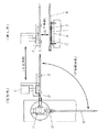
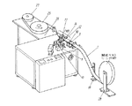
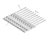
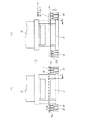
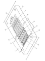
図1は本実施の形態における成形金型へ搬送供給される柔軟かつ可塑性でなる被搬送供給部材の斜視図、図2は本実施の形態における被搬送供給部材を保持し搬送して成形金型へ搬入搬出を行う搬送ベルトの斜視図、断面図および各部の詳細平面および側面図、図3は同被搬送供給部材の供給取出部の要部概略正面図、図4は同側面および概要動作図、図5は同被搬送供給部材のフィーダ要部概要平面および側面図、図6および図7は同被搬送供給部材の搬送ベルトへの投入動作の要部概要説明図、図8は同被搬送供給部材と搬送ベルト関連における要部概要平面および側面図、図9は同機構の要部斜視図、図10は同図9におけるC部の斜視図、図11は本実施の形態における搬送ベルトを使用した成形装置の要部斜視図、図12は同図11におけるE部の斜視図、図13は同図11におけるD部の要部正面図、図14は同図11におけるD部の要部斜視図、図15は同図13におけるF部およびG部の要部矢視図、図16は同成形金型における要部斜視図、そして図17は同搬送ベルトから成形済み被搬送供給部材の取出しにおける概要動作説明図である。 FIG. 1 is a perspective view of a flexible and plastic to-be-conveyed supply member that is conveyed and supplied to a molding die in the present embodiment, and FIG. 2 is a molding die that holds and conveys the to-be-conveyed supply member in the present embodiment. FIG. 3 is a schematic front view of a main portion of a supply / extraction portion of the transported supply member, and FIG. 4 is a side view and a schematic operation diagram thereof. FIG. 5 is a plan view and a side view of an outline of a feeder main part of the transported supply member. FIGS. 6 and 7 are explanatory views of a main part of an operation of loading the transported supply member onto a transport belt. FIG. FIG. 9 is a perspective view of the main part of the mechanism, FIG. 10 is a perspective view of part C in FIG. 9, and FIG. 11 is the transport belt in the present embodiment. FIG. 12 is a perspective view of the main part of the molding apparatus used, and FIG. 13 is a perspective view of the main part of the D part in FIG. 11, FIG. 14 is a perspective view of the main part of the D part in FIG. 11, and FIG. 15 is a perspective view of the F part and the G part in FIG. FIG. 16 is a perspective view of a main part of the molding die, and FIG. 17 is a schematic operation explanatory view of taking out a formed transported supply member from the transport belt.
図1〜図17において、90は本実施の形態におけるワークの柔軟かつ可塑性である被搬送供給部材であり、線材56を用いた素材、被成形体あるいは成形製品の形態である。
In FIG. 1 to FIG. 17,
詳細には線材56の片端に突起91を有する被成形体を90a、付属物が無く線材56のみの被成形体を90b、被成形体90aの他端が所定成形された成形製品を90c、そして被成形体90bの一端が所定の樹脂成形された成形製品を90dなどである。
Specifically, 90a is a molded body having a
1は線材56あるいは被搬送供給部材90を載置し保持および搬送(移動)を行うための搬送ベルトであり、帯板状のスチールベルト8を所定の成形加工したもので、リサイクルが容易すなわち複数回の使用が可能である。
Reference numeral 1 denotes a conveyor belt for placing and holding and conveying (moving) the wire material 56 or the to-
2は搬送ベルト1の位置決めと搬送駆動用に搬送ベルト1の両側帯部に定間隔で設けた位置決め孔、3は搬送ベルト1にインサート樹脂成形により形成して搭載され、挿入保持溝を有する対の保持部であり、線材56や被成形体90a〜90dまたは成形製品90を所定箇所に高精度で位置決めを行う。
2 is a positioning hole provided at regular intervals on both sides of the conveyor belt 1 for positioning and driving of the conveyor belt 1, and 3 is a pair formed by insertion resin molding on the conveyor belt 1 and having an insertion holding groove. This is a holding part for positioning the wire 56, the molded bodies 90a to 90d or the molded
そして、この保持部3を必要な所定の形状にすることにより、各種の線材56あるいは被搬送供給部材90、すなわち各種のワークに対応することが可能であり、搬送ベルト1は成形品種が変更になっても使用することができる。
And by making this holding | maintenance part 3 into the required predetermined shape, it can respond to various wire 56 or the to-
4は搬送ベルト1の両側帯部に設けられ、成形金型内でワーク(被搬送供給部材)のそりやゆがみの発生を防ぐために製品バックアップを行う部材の逃げのための角穴、5は搬送ベルト1の幅の中央部に設けられた長角穴であり、成形金型内にワークを搬入供給し成形する際、後で説明するが金型内で高精度位置決めを行うための製品ガイド部47が、ワークをガイドできるようにするために設けてある。 4 is provided on both side belt portions of the conveyor belt 1, and square holes for escaping a member that backs up the product in order to prevent warpage and distortion of the workpiece (conveyed supply member) in the molding die, 5 are conveyed This is a long hole provided in the center of the width of the belt 1, and will be described later when a workpiece is carried in and fed into a molding die, and a product guide portion for performing high-precision positioning in the die. 47 is provided so that the workpiece can be guided.
6は保持部3をインサート成形して搭載するために、その所定箇所に設けられた角穴、7は保持部3の中央の下部に設けられた孔であり、保持部3に載置されたワークを搬送ベルト1から除去(取り出す)するために、角穴6および孔7から排除用のピンなどを押し上げ挿通させるためのものである。
7aは後で説明する突き上げピン53の挿通をガイドするためのテーパー部であり、8は保持部3を成形して搭載する前の状態、すなわち搬送ベルト1の本体ベースであるところのスチールベルトである。
Reference numeral 7a denotes a taper portion for guiding insertion of the push-up
9は線材56あるいは被搬送供給部材90の整列および供給を行うためのラインフィーダー、10はラインフィーダー9における線材56あるいは被搬送供給部材90の供給を規制し案内するガイド、11は供給された線材56あるいは被搬送供給部材90を取り出すためのチャック、12はチャック11の一端に設けられ、線材56あるいは被搬送供給部材90を移載するために実際に線材56あるいは被搬送供給部材90の片端を挟持する爪である。
9 is a line feeder for aligning and supplying the wire 56 or the transported
13は取り出した線材56あるいは被搬送供給部材90を爪12で挟持した後、方向を90度変更させるために回動あるいは揺動させるためのロータリーアクチュエータなどでなる駆動部、14は方向を90度変更した線材56あるいは被搬送供給部材90を受け取るためのチャック、15はバックアップ爪であり、搬送ベルト1の保持部3に線材56あるいは被搬送供給部材90を挿入する際、線材56あるいは被搬送供給部材90の上側をバックアップしながら押圧して押し入れるのである。
Reference numeral 13 denotes a drive unit composed of a rotary actuator or the like for rotating or swinging in order to change the direction by 90 degrees after the picked-up wire 56 or the transported
16は爪であり、チャック14の一端に設けられ、線材56あるいは被搬送供給部材90を爪12の把持から受け取って把持し、それを搬送ベルト1の保持部3に投入する。17は搬送ベルト1の移動経路において規制しガイドするための上ガイドレール、18は同じく搬送ベルト1の移送経路において規制しガイドするための上ガイドレール17とは対の下ガイドレールである。
19は位置決めピンであり、線材56あるいは被搬送供給部材90を搬送ベルト1に移し替える際に、搬送ベルト1の位置決め孔2の中に挿入して搬送ベルト1を所定箇所に位置決めする。20は位置決めピン19を上下移動させるための駆動部、21は位置決め孔2に位置決めピン19が挿入されなかった際に、ピン19を損傷させずにたわませるためのバネ、22はピン19がたわんだ事を検出するためのセンサー、23は搬送ベルト1を位置決め孔2を使って高精度に位置決め搬送を行うための回動自在なピンホイール、24はピンホイール23を回動させるための駆動軸であり、ピンホイール駆動部97により回転駆動させる。
A
25は搬送ベルト1の保持部3に投入され保持された線材56あるいは被搬送供給部材90を載置した搬送ベルト1を巻き取るためのリール、26はリール25の駆動制御機構、27は搬送ベルト1を巻き取る際に線材56あるいは被搬送供給部材90に歪みやキズなどの損傷を防ぐために、一緒に重ねて巻取りを行う干渉用の合紙や布テープなどの供給部、28は搬送ベルト1を巻出すリール機構、29は線材56あるいは被搬送供給部材90が巻き取られたリール25を駆動し巻き出すための巻出機構である。
30は搬送ベルト1と一緒に重ねて巻かれた合紙や布テープを巻き取る巻取部、31は搬送ベルト1の搬送をスムースに行うための移動あるいは揺動自在な供給ダンサー、32は被成形体の成形加工や搬送ベルト1による搬送などを行う成形機構、33は成形機、34は成形後に被搬送供給部材90に残存するランナー部50を切断分離除去するための切断分離機構を駆動する駆動部、35は成形金型、36は不要なランナー部50の切断分離を行うための切断分離機構を構成する切断金型、37aは左搬送ベルトガイドそして37bは右搬送ベルトガイドでありガイド部37を構成しており、搬送ベルト1の搬送における送り高さを上下移動および設定することができる。
38はランナー部を切断分離された線材56あるいは被搬送供給部材90を搬送ベルト1から排除(取り出す)するためのチャック、39はチャック38を上下あるいは左右移動させるためのロボット、40は搬送ベルト1から線材56あるいは被搬送供給部材90が排除(取り出し)され、何も搭載し保持されていない搬送ベルト1を巻き取る巻取部、41は搬送ベルト1を高精度に位置決めしかつ送出するために、ピンホイール駆動部97および駆動軸24によるピンホイール23の回転動作で搬送ベルト1の移動搬送を行う送出部である。
42は成形金型35の内で搬送ベルト1の位置決めを行うための位置決めピン、43は線材56あるいは被搬送供給部材90を成形金型35へ投入する際、左右方向の位置決めを行うためのガイドブロック、44はランナー部が形成されるランナー溝、44aは成形加工において樹脂などで形成されたゲート部、45は成形を行う際に成形部分が形成される空洞部、46は線材56あるいは被搬送供給部材90に対する規制あるいはガイドを行う製品ガイド部、47も同じく線材56あるいは被搬送供給部材90に対する規制あるいはガイドを行う製品ガイド部、92は成形金型内でのワークである被搬送供給部材90の反りや移動などを防止するための突起である製品バックアップである。
42 is a positioning pin for positioning the conveyor belt 1 in the molding die 35, and 43 is a guide for positioning in the left-right direction when the wire 56 or the transported
48は搬送ベルト1のガイド部37を上下移動させるための駆動部、49はガイド部37を高精度に上下移動させるために規制し摺動させる軸受け部、50は成形後に線材56あるいは被搬送供給部材90に残存している樹脂材のランナー部、51はバックアップ爪であり、線材56あるいは被搬送供給部材90を搬送ベルト1から排除(取り出す)する際、線材56あるいは被搬送供給部材90の上面を受けるチャック38の一端(先端)部分に配置されている。
48 is a drive unit for moving the
52は線材56あるいは被搬送供給部材90を搬送ベルト1から排除(取り出す)するための挟持用の爪、53は突き上げピンであり、線材56あるいは被搬送供給部材90を排除(取り出す)する際、搬送ベルト1の保持部3に設けられた孔7を挿通させて、線材56あるいは被搬送供給部材90を押し上げ、保持部3から分離離脱させるのである。そして54は突き上げピン53に対する押圧力の付勢あるいは調整するためのバネである。
52 is a clamping claw for removing (removing) the wire 56 or the transported
また、80はチャック38およびロボット39の近傍に配設され、成形完成製品を保管し搬送する成形製品投入箱、81は搬送ベルトに配置され、ワークの一端を固定保持あるいはガイドする固定ガイド、93はチャック11を上下移動させるための駆動部であるガイド付シリンダー、94はガイド付シリンダー93の一端に固着され駆動部13を保持するホルダーブロック、95はチャック11を保持し駆動部13に連結接続するブラケット、96は被搬送供給部材90を停止させ保持するストッパー、98は搬送ベルト1を凹部溝にて規制しガイドするベルトガイドである。
Further, 80 is disposed in the vicinity of the
99は光学あるいは機械式で搬送ベルト1の状態や状況を検出する搬送ベルト供給ON/OFFセンサーであり、図9に示す機械式の搬送ベルト供給ON/OFFセンサー99においては、上側の検出ピンに搬送ベルト1が当接すると供給を開始し、搬送ベルト1が下側の検出ピンに当接すると供給を停止する。 Reference numeral 99 denotes an optical or mechanical conveyance belt supply ON / OFF sensor that detects the state and condition of the conveyance belt 1. In the mechanical conveyance belt supply ON / OFF sensor 99 shown in FIG. Supply starts when the conveyor belt 1 abuts and stops when the conveyor belt 1 abuts the lower detection pin.
さらにまた、100は固定ガイド81を上面に配設し搬送ベルト1を上面で摺動させるレール、101は下面にチャック38およびバックアップ爪51を装着し、上面の両側に上下用ガイド102を配設したプレート104を駆動させる上下駆動部、103は上下駆動部101と上下用ガイド102をロボット39に装着するためのブラケット、105は上下駆動部101とプレート104を連結するロッドエンドである。
Furthermore, 100 is a rail on which a fixed
以上のように構成された本発明による成形金型における部材搬送供給方法およびその装置の動作について図面を参照しながら説明する。 The member conveying and supplying method and the operation of the apparatus in the molding die configured as described above according to the present invention will be described with reference to the drawings.
図3、図4、図5および図6(a)に示すように、まず、はじめに柔軟かつ可塑性である線材56あるいは被搬送供給部材90を、ラインフィーダー9により整列あるいは配列し、ガイド10に規制かつガイドされてラインフィーダー9の先端所定箇所に移動して待機させる。
As shown in FIGS. 3, 4, 5, and 6 (a), first, the flexible and plastic wire 56 or the transported
供給され待機した線材56は、図3および図6(b)に示すように上下移動自在なチャック11がガイド付シリンダー93の駆動により下降し、チャック11の一端に配置された爪12により線材56の一端を把持して挟持される。そして、爪12により把持し挟持した後、図6(c)に示すようにチャック11をガイド付シリンダー93の駆動により上昇させ、チャック11が上昇した後、図3に示す駆動部13(ロータリーアクチュエータ)の駆動により、チャック11を90度回動すなわち揺動して、図4および図6(d)に示すように水平状態にする。
As shown in FIGS. 3 and 6B, the wire 56 that has been supplied and waits for the chuck 11, which is movable up and down, to descend by driving the
90度回動した線材56は、図4および図7(a)に示すようにガイド付シリンダー93の駆動により右方向へ移動しかつ水平方向の姿勢になるが、この時、線材56の水平姿勢の位置には、この線材56を受け取るためのチャック14が待機しており、線材56が水平方向になると、チャック14の一端に配置された爪16により線材56の一端を把持して挟持する。
As shown in FIGS. 4 and 7A, the wire 56 rotated 90 degrees moves to the right by the driving of the
線材56の一端が把持し挟持されると、図7(b)に示すようにチャック11は、爪12による線材56の一端を把持による挟持を解除してチャック14への受け渡しを完了して元の位置に復帰する。
When one end of the wire 56 is gripped and clamped, as shown in FIG. 7B, the chuck 11 releases the gripping of one end of the wire 56 by the
なお、このチャック14は図4にも示しているが、受け取り側と挿入側の2箇所の位置を図の矢印の左右すなわち水平への移動、および上下すなわち垂直への移動ができる駆動機構(図示せず)を有しているのであり、線材56を把持し挟持した後、チャック14は挿入側への水平移動を行うのである。 Although the chuck 14 is also shown in FIG. 4, a drive mechanism (see FIG. 4) that can move the positions of the receiving side and the insertion side in the left and right directions, that is, in the horizontal direction, and in the vertical direction, that is, in the vertical direction. After gripping and pinching the wire material 56, the chuck 14 moves horizontally to the insertion side.
挿入側には、線材56を高精度に位置決め保持し樹脂成形を行うための搬送ベルト1が、上ガイドレール17および下ガイドレール18で規制しガイドされながら図8に示す位置決めピン19による所定の位置で待機している。 On the insertion side, the conveying belt 1 for positioning and holding the wire 56 with high accuracy and performing resin molding is regulated by the upper guide rail 17 and the lower guide rail 18 and guided by the positioning pins 19 shown in FIG. Waiting at position.
従って線材56が水平移動した後、チャック14を降下させて搬送ベルト1における保持部3へ線材56を挿入し載置するのであるが、柔軟かつ可塑性の線材56を挿入する際には曲がりや屈折の発生などの挿入における支障を防ぐため、チャック14にあらかじめ線材56を把持し保持しており、線材56をチャッキングする際に線材56の直上に配設しているバックアップ爪15により線材56を上から押し込むことにより挿入性を上げている。
Therefore, after the wire 56 is moved horizontally, the chuck 14 is lowered and the wire 56 is inserted and placed on the holding portion 3 of the conveyor belt 1. However, when the flexible and plastic wire 56 is inserted, bending or refraction is performed. In order to prevent troubles in insertion such as the occurrence of the wire 56, the wire 56 is held and held in advance by the chuck 14, and when the wire 56 is chucked, the wire 56 is held by the
そして線材56が保持部3に挿入された後、図7(c)、図7(d)および図4に示すようにチャック14における爪16は線材56の把持による挟持を解除し、線材56すなわち被搬送供給部材90の搬送ベルト1の保持部3への挿入すなわち移載が完了するのである。
Then, after the wire 56 is inserted into the holding portion 3, as shown in FIGS. 7C, 7D and 4, the
搬送ベルト1の保持部3に挿入された線材56は、図8に示す駆動軸24を介したピンホイール駆動部97によるピンホイール23の回転により間欠搬送が行われるのであり、間欠搬送された後は駆動部20による位置決めピン19の先端を位置決め孔2へ挿入する事により、搬送ベルト1を所定位置決めあるいは設定を行う。
The wire 56 inserted into the holding unit 3 of the conveyance belt 1 is intermittently conveyed by the rotation of the
もし搬送ベルト1の送り(移動)位置がずれた場合には、位置決めピン19は位置決め孔2に挿入されないのであり、そのためにバネ21がたわんで位置決めピン19は上方向に進出しないことになるのであり、その状態をセンサー22で検出し、自動あるいは手動で修正あるいは補正を行うことにより挿入ミスを防いでいる。
If the feeding (moving) position of the conveyor belt 1 is deviated, the
線材56を搬送ベルト1の保持部3へ挿入した後は、図9に示すように、順次搬送を行って駆動制御機構26の駆動により、図10に示す状態でリール25に巻き取るのであり、その際、必要に応じて合紙の供給部27より供給される合紙を同時に重ねて巻き取る。
After inserting the wire 56 into the holding unit 3 of the conveyor belt 1, as shown in FIG. 9, it is sequentially conveyed and wound around the
このようにして、線材56を搬送ベルト1の保持部3に整列挿入した搬送ベルト1を巻回したリール25を次に巻出機構29へセットする。すなわち、図11に示す巻出機構29および成形機構32において、巻出機構29にリール25をセットして合紙を巻取部30で巻取りながら供給ダンサー31を介して、成形機構32へ移送し搬送供給を行っていく。
In this way, the
成形機構32へは搬送ベルト1の送出部41を介して供給されるのであり、搬送ベルト1は図13(a)に示すように成形機33の入口と出口の両側に配置された左搬送ベルトガイド37a、右搬送ベルトガイド37bにより規制しガイドされながら移送され、図13(b)に示すように駆動部48を下降させることで、左搬送ベルトガイド37aおよび右搬送ベルトガイド37bが下降、すなわち搬送ベルト1が成形機33の金型の所定箇所にセットされることになる。
It is supplied to the forming mechanism 32 via the delivery part 41 of the transport belt 1, and the transport belt 1 is a left transport belt disposed on both sides of the inlet and outlet of the
搬送ベルト1は図14に示すように、成形金型35の直上の位置になるように左搬送ベルトガイド37aおよび右搬送ベルトガイド37bを、駆動部48の上部先端に接続配置させ、所定の移送が完了すると左搬送ベルトガイド37aおよび右搬送ベルトガイド37bを駆動部48の駆動により下降させ、それと同時に搬送ベルト1をも下降させる。
As shown in FIG. 14, the conveyor belt 1 has a left
このとき、位置決めピン42の先端部を、搬送ベルト1の位置決め孔2に挿入させることで、成形金型35における搬送ベルト1の位置決めを行うのであり、その結果、被成形体である線材56が成形金型35内の製品ガイド部46、製品ガイド部47に挿入され、被成形体である線材56の長手方向への位置決めも、下降する時にガイドブロック43により図15(a)、図15(b)に示すように、被成形体である線材56の左先端部をガイドブロック43のテーパー部で規制しガイドすることにより行うのである。
At this time, the leading end portion of the positioning pin 42 is inserted into the
その結果、所定形状の樹脂成形がなされて、被成形体である線材56の樹脂成形外形となる成形金型35内の空洞部45への投入分も高精度となり、成形機33から投入される樹脂量などのばらつきを小さくでき、高品質で安定した樹脂成形が行えることになる。
As a result, resin molding of a predetermined shape is performed, and the amount of the wire 56 that is the molding target to be inserted into the
前記の被成形体である線材56の挿入が完了すると、所定の樹脂成形を行い、樹脂成形が完了した後は、再度、駆動部48の駆動により左搬送ベルトガイド37aおよび右搬送ベルトガイド37bを上昇させることで、搬送ベルト1を上昇させ、成形金型内から樹脂成形された成形体である線材56すなわち被搬送供給部材90も同時に取り出す。
When the insertion of the wire material 56, which is the object to be molded, is completed, predetermined resin molding is performed. After the resin molding is completed, the left
そして、搬送ベルト1の上昇が完了すると、再度、搬送ベルト1の送出部41により搬送ベルト1を所定箇所へ移送する。 When the raising of the conveyor belt 1 is completed, the conveyor belt 1 is again transferred to a predetermined location by the delivery unit 41 of the conveyor belt 1.
線材56すなわち被成形体は複数本同時に樹脂成形を行うが、この際、成形金型35内のランナー溝44における樹脂のランナー部50も同時に成形され、線材56すなわち成形体に付着してくるため、これを取り除く必要がある。
A plurality of wires 56, that is, moldings, are molded simultaneously. At this time, the resin runner portion 50 in the
従って成形機33の横近傍には図11に示すように、この樹脂のランナー部50を取り除き除去するランナー部50の切断金型36が配置されており、樹脂成形後には、搬送ベルト1によりここまで搬送されてきた成形体である線材56すなわち被搬送供給部材90は、駆動部34により駆動されるランナー部50の切断金型36により樹脂のランナー部50を切断分離し除去して完成した成形製品となる。
Accordingly, as shown in FIG. 11, a cutting die 36 for the runner 50 that removes and removes the resin runner 50 is disposed near the side of the
またその横近傍には完成して成形製品となった被搬送供給部材90を搬送ベルト1から取り出すために、上下移動自在なチャック38が配置されており、図17に示すように、搬送ベルト1は固定ガイド81で規制しガイドされており、その状態でチャック38が下降してくる。
Further, in the vicinity of the side, a
その際チャック38にはバックアップ爪51が配置されており、搬送ベルト1における保持部3の位置での成形製品となった被搬送供給部材90を押さえ込み、その後に爪52により成形製品となった被搬送供給部材90を把持し挟持し、保持しながら搬送ベルト1からの取り出しを行う。
At this time, the backup claw 51 is disposed on the
しかし、成形製品となった被搬送供給部材90は搬送ベルト1に高精度に保持するため強く把持し挟持されており、簡単には搬送ベルト1からは離脱できないので、あらかじめ搬送ベルト1の保持部2の中に配設された孔7から、突き上げピン53の上下駆動による突き上げで、成形製品となった被搬送供給部材90をバックアップ爪51とで挟持しながらチャック38を上昇させることで、安定かつ確実に成形製品となった被搬送供給部材90を搬送ベルト1から取り出すのである。
However, the transported
またこの際、挟持する力を一定とするため、突き上げピン53には図17(c)に示すようにバネ54による張力が付勢されている。
At this time, in order to keep the clamping force constant, the push-up
チャック38により搬送ベルト1より取り出された成形製品となった被搬送供給部材90は、ロボット39の駆動動作により搬送あるいは移送して、完成して成形製品となった被搬送供給部材90を投入し保管する成形製品投入箱80の中へ投入あるいは整列される。
The to-
成形製品となった被搬送供給部材90が取り出された後の搬送ベルト1は、送出部41により、搬送ベルト1の巻取部40で再度リール25に巻き取られるが、この搬送ベルト1は再度繰り返し利用することが可能であり、図9のリール機構28へ設置することで、廃棄することなく再利用が可能となるのである。
The transport belt 1 after the transported
また、他のリードフレームに樹脂モールドなどで成形する方法で製作できるものであっても、本発明の方法および装置を採用することにより、個片に切断された後のリードフレームを廃棄するしかなく、再利用することができなかったものに対して、再利用が可能となり経済的でコスト面においても優れているのである。 Further, even if the lead frame can be manufactured by a method such as molding with a resin mold, the lead frame after being cut into individual pieces can only be discarded by using the method and apparatus of the present invention. The thing that could not be reused can be reused and is economical and excellent in terms of cost.
なお本実施の形態では、ワークにこしを有しない柔軟かつ可塑性の線材を樹脂成形するための成形金型における部材搬送供給方法およびその装置を例に説明したが、他の部品や部材の搬送、供給および搬出を行う装置としても有効に活用できることは言うまでもない。 In the present embodiment, the member conveying and supplying method and its apparatus in a molding die for resin-molding a flexible and plastic wire having no strain on the workpiece have been described as an example. Needless to say, it can also be used effectively as a device for supplying and unloading.
本発明にかかる成形金型における部材搬送供給方法およびその装置は、簡素な構成で操作が容易であり、信頼性と生産性が優れ、安定した高品質な自動化による連続成形ができ、被搬送供給部材が柔軟かつ可塑性を有する線材のようなリードフレームでの生産が困難な成形製品であっても、作業者によるハンド生産が不要で自動化が可能であり、使用後のリードフレーム相当を廃棄すること無く、フープ状の搬送ベルトを再利用することができるという効果を有し、電子部品の製造分野のみでなく、各種の分野における部材搬送供給方法およびその装置などの用途として有用である。 The method and apparatus for conveying and conveying a member in a molding die according to the present invention is easy to operate with a simple configuration, is excellent in reliability and productivity, can be continuously formed by stable and high-quality automation, and is supplied and conveyed. Even if it is a molded product that is difficult to produce with a lead frame such as a flexible and plastic wire material, it is possible to automate without requiring hand production by the operator, and discard the lead frame equivalent after use The hoop-shaped transport belt can be reused, and is useful not only in the field of manufacturing electronic components but also in various fields such as a member transport and supply method and apparatus.
1 搬送ベルト
2 位置決め孔
3 保持部
4、6 角穴
5 長角穴
7 孔
7a テーパー部
8 スチールベルト
9 ラインフィーダー
10 ガイド
11、14、38 チャック
12、16、52 爪
13 駆動部(ロータリーアクチュエータ)
15、51 バックアップ爪
17 上ガイドレール
18 下ガイドレール
19、42 位置決めピン
20、34、48 駆動部
21、54 バネ
22 センサー
23 ピンホイール
24 駆動軸
25 リール
26 駆動制御機構
27 供給部
28 リール機構
29 巻出機構
30、40 巻取部
31 供給ダンサー
32 成形機構
33 成形機
35 成形金型
36 切断金型
37 ガイド部
37a 左搬送ベルトガイド
37b 右搬送ベルトガイド
39 ロボット
41 送出部
43 ガイドブロック
44 ランナー溝
44a ゲート部
45 空洞部
46、47 製品ガイド部
49 軸受け部
50 ランナー部
53 突き上げピン
55 リードフレーム
56、59 線材
57 成形樹脂部
58 成形完成品
60 帯部
61、62 分離切断部
63、64 切断部
80 成形製品投入箱
81 固定ガイド
90 被搬送供給部材
90a、90b 被成形体
90c、90d 成形製品
91 突起
92 製品バックアップ
93 ガイド付シリンダー
94 ホルダーブロック
95、103 ブラケット
96 ストッパー
97 ピンホイール駆動部
98 ベルトガイド
99 搬送ベルト供給ON/OFFセンサー
100 レール
101 上下駆動部
102 上下用ガイド
104 プレート
105 ロッドエンド
DESCRIPTION OF SYMBOLS 1
15, 51 Backup claw 17 Upper guide rail 18
Claims (4)
Priority Applications (1)
| Application Number | Priority Date | Filing Date | Title |
|---|---|---|---|
| JP2005139533A JP4380588B2 (en) | 2005-05-12 | 2005-05-12 | Method and apparatus for conveying and feeding members in a molding die |
Applications Claiming Priority (1)
| Application Number | Priority Date | Filing Date | Title |
|---|---|---|---|
| JP2005139533A JP4380588B2 (en) | 2005-05-12 | 2005-05-12 | Method and apparatus for conveying and feeding members in a molding die |
Publications (2)
| Publication Number | Publication Date |
|---|---|
| JP2006315270A JP2006315270A (en) | 2006-11-24 |
| JP4380588B2 true JP4380588B2 (en) | 2009-12-09 |
Family
ID=37536358
Family Applications (1)
| Application Number | Title | Priority Date | Filing Date |
|---|---|---|---|
| JP2005139533A Expired - Fee Related JP4380588B2 (en) | 2005-05-12 | 2005-05-12 | Method and apparatus for conveying and feeding members in a molding die |
Country Status (1)
| Country | Link |
|---|---|
| JP (1) | JP4380588B2 (en) |
Families Citing this family (4)
| Publication number | Priority date | Publication date | Assignee | Title |
|---|---|---|---|---|
| JP2016022659A (en) * | 2014-07-18 | 2016-02-08 | 株式会社明王化成 | Insert molding mold and insert molding method |
| CN110253828B (en) * | 2019-07-10 | 2023-09-22 | 深圳市锴诚精密模具有限公司 | Full-automatic production equipment for processing paper discharge guide plate and control method thereof |
| CN111590816B (en) * | 2020-06-03 | 2021-11-30 | 赵乾 | Progressive conveying assembly of automatic clamping mechanism for metal inserts in injection molding production |
| CN117428446B (en) * | 2023-12-21 | 2024-03-22 | 广东敏卓机电股份有限公司 | Bearing assembly devices and motor assembly equipment |
-
2005
- 2005-05-12 JP JP2005139533A patent/JP4380588B2/en not_active Expired - Fee Related
Also Published As
| Publication number | Publication date |
|---|---|
| JP2006315270A (en) | 2006-11-24 |
Similar Documents
| Publication | Publication Date | Title |
|---|---|---|
| JP6363606B2 (en) | Component mounting equipment | |
| JP4888582B2 (en) | Robot device, processing system, and method of manufacturing processed product | |
| WO2013132599A1 (en) | Automated tape setting apparatus | |
| JP6334689B2 (en) | feeder | |
| JPWO2015029124A1 (en) | feeder | |
| KR970013249A (en) | Automatic mold device using release film | |
| JP4380588B2 (en) | Method and apparatus for conveying and feeding members in a molding die | |
| US10412868B2 (en) | System and method for separating workpieces | |
| JP5448887B2 (en) | Spliced carrier tape, detection mark applied to the carrier tape, method of feeding the carrier tape, and component supply device | |
| TWI400362B (en) | Board unloading device and board unloading method | |
| TWI527531B (en) | Handle providing apparatus of slider assembling machine and handle positioning portion thereof | |
| CN111356642B (en) | Bundling and packaging device | |
| CN110125643B (en) | Full-automatic ribbon assembling machine | |
| JP2007084298A (en) | Sheet transfer and stacking device and automatic sheet bundle packaging system | |
| JP5160819B2 (en) | Electronic component mounting apparatus and mounting method | |
| CN107490578B (en) | Semiconductor element inspection device | |
| JP2006326813A (en) | Automatically assembling device for thin-wall component laminate, and packing type structure equipped with thin-wall component | |
| KR102163191B1 (en) | Apparatus for attaching label on top of container | |
| CN110911333A (en) | Tape sticking apparatus | |
| KR101871377B1 (en) | laser marking device for lens barrel | |
| JP2012111078A (en) | Device for supplying and attaching rubber member and method of molding tire member using the same | |
| JPH04265719A (en) | Insert molding method and apparatus | |
| JP2013118387A (en) | Mounting device and mounting method for electronic component | |
| KR100568667B1 (en) | Separating device of guide for flexible substrate | |
| JP6543750B2 (en) | Component mounting device |
Legal Events
| Date | Code | Title | Description |
|---|---|---|---|
| A621 | Written request for application examination |
Free format text: JAPANESE INTERMEDIATE CODE: A621 Effective date: 20070226 |
|
| RD01 | Notification of change of attorney |
Free format text: JAPANESE INTERMEDIATE CODE: A7421 Effective date: 20070313 |
|
| A977 | Report on retrieval |
Free format text: JAPANESE INTERMEDIATE CODE: A971007 Effective date: 20090519 |
|
| A131 | Notification of reasons for refusal |
Free format text: JAPANESE INTERMEDIATE CODE: A131 Effective date: 20090526 |
|
| A521 | Written amendment |
Free format text: JAPANESE INTERMEDIATE CODE: A523 Effective date: 20090724 |
|
| TRDD | Decision of grant or rejection written | ||
| A01 | Written decision to grant a patent or to grant a registration (utility model) |
Free format text: JAPANESE INTERMEDIATE CODE: A01 Effective date: 20090901 |
|
| A01 | Written decision to grant a patent or to grant a registration (utility model) |
Free format text: JAPANESE INTERMEDIATE CODE: A01 |
|
| A61 | First payment of annual fees (during grant procedure) |
Free format text: JAPANESE INTERMEDIATE CODE: A61 Effective date: 20090914 |
|
| FPAY | Renewal fee payment (event date is renewal date of database) |
Free format text: PAYMENT UNTIL: 20121002 Year of fee payment: 3 |
|
| FPAY | Renewal fee payment (event date is renewal date of database) |
Free format text: PAYMENT UNTIL: 20121002 Year of fee payment: 3 |
|
| FPAY | Renewal fee payment (event date is renewal date of database) |
Free format text: PAYMENT UNTIL: 20131002 Year of fee payment: 4 |
|
| LAPS | Cancellation because of no payment of annual fees |