JP4378039B2 - Motor, light amount adjusting device, and lens barrel - Google Patents
Motor, light amount adjusting device, and lens barrel Download PDFInfo
- Publication number
- JP4378039B2 JP4378039B2 JP2000228087A JP2000228087A JP4378039B2 JP 4378039 B2 JP4378039 B2 JP 4378039B2 JP 2000228087 A JP2000228087 A JP 2000228087A JP 2000228087 A JP2000228087 A JP 2000228087A JP 4378039 B2 JP4378039 B2 JP 4378039B2
- Authority
- JP
- Japan
- Prior art keywords
- magnet
- magnetic pole
- stator
- motor
- peripheral surface
- Prior art date
- Legal status (The legal status is an assumption and is not a legal conclusion. Google has not performed a legal analysis and makes no representation as to the accuracy of the status listed.)
- Expired - Fee Related
Links
Images


Landscapes
- Lens Barrels (AREA)
- Diaphragms For Cameras (AREA)
Description
【0001】
【産業上の利用分野】
本発明は、超小型に構成したモータとそれを用いた光量調整装置とレンズ鏡筒に関する。
【0002】
【従来の技術】
従来の小型円筒形状のステップモータとしては図8に示すものがある。ボビン101にステータコイル105が同心状に巻回され、ボビン101は2個のステータヨーク106で軸方向から挟持固定されており、かつステータヨーク106にはボビン101の内径面円周方向にステータ歯106aと106bが交互に配置され、ケース103には、ステータ歯106aまたは106bと一体のステータヨーク106が固定されてステータ102が構成されている。
【0003】
2組のケース103の一方にはフランジ115と軸受け108が固定され、他方のケース103には他の軸受け108が固定されている。ロータ109はロータ軸110に固定されたロータ磁石111からなり、ロータ磁石111はステータ102のステータヨーク106aと放射状の空隙部を形成している。そして、ロータ軸110は2個の軸受け108の間に回転可能に支持されている。
【0004】
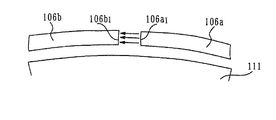
しかしながら、図8に示す上記従来の小型のステップモータはロータの外周にケース103、ボビン101、ステータコイル105、ステータヨーク106が同心状に配置されているためモータの外形寸法が大きくなってしまう欠点があった。また、ステータコイル105への通電により発生する磁束は図9に示すように主としてステータ歯106aの端面106a1とステータ歯106bの端面106b1とを通過するためロータ磁石111に効果的に作用しないのでモータの出力は高くならない欠点がある。
【0005】
本出願人はこのような問題を解決したモータを特開平09−331666に提案している。この提案されたモータは円周方向に等分割して異なる極に交互に着磁された永久磁石からなるロータを円筒形状に形成し、該ロータの軸方向に第1のコイル、ロータ及び第2のコイルを順に配置し、第1のコイルにより励磁される第1の外側磁極及び第1の内側磁極をロータの外周面及び内周面に対向させ、第2のコイルにより励磁される第2の外側磁極及び第2の内側磁極をロータの外周面及び内周面に対向させる様に構成したものであり、ロータ軸である回転軸が円筒形状の永久磁石内から取り出されている。
【0006】
このような構成のモータは、出力が高くモータの外形寸法を小さいものとする事ができるがロータ軸と永久磁石との接合の容易化が望まれる。さらに上記構成ではマグネットを薄くすることにより第1の外側磁極と第1の内側磁極の間の距離及び第2の外側磁極と第2の内側磁極の間の距離を結果的に小さくでき磁気回路の磁気抵抗を小さくする事ができる。これによれば第1のコイル及び第2のコイルに流す電流は少ない電流で多くの磁束を発生させる事ができる。
【0007】
【発明が解決しようとする課題】
しかしながら、上記特開平09−331666等で記載されているタイプのモータは中実の円筒形状であったため、カメラの鏡筒内で光軸と平行になるように配置し絞り羽根やシャッタ、レンズ等を駆動するために用いようとした場合鏡筒の半径寸法はレンズの半径や絞り開口の半径寸法にモータの直径を加えた値になりカメラの鏡筒の直径は十分小さいものにはならなかった。
【0008】
図10にその様子を示す。モータをM、鏡筒地板或いは光量調節装置を300、開口部を301としモータMの直径をD1、開口部301の直径をD2、鏡筒地板300の直径をD3とすると鏡筒地板300の直径D3は少なくとも(2×D1+D2)以上になってしまう。このような用途に対して半径方向の厚さ寸法の薄いドーナツ型のモータが望まれていた。また鏡筒装置或いは光量調節装置に関してもコンパクト化が望まれている。
【0009】
また、中空のドーナツ形状のモータにより絞り羽根を駆動するものは例えば特開昭53−37745や特開昭57−166847等で提案されている。これらは中空状のマグネット外側にコイルを巻く形状になっている為コイルの厚みとマグネットの厚みとステータの厚みがすべて半径方向の厚みに加算されてしまい半径方向の厚さ寸法の薄いドーナツ型のモータとしては十分ではなかった。
【0010】
さらに、レンズを駆動するものは実開昭56−172827等で提案されている。これはコイルの中心軸が鏡筒の光軸中心に向かう方向に配置されている為コイル形状が複雑になったり組み立てが複雑になったりして部品点数が増えて装置自体がコンパクトにならなかったりコイルの個数が増してしまいコストも高くなってしまう問題点が有った。
【0011】
本発明の目的は、第1に、出力が高く特に半径方向に関して薄い円筒状のモータを提供することにある。
【0012】
本発明の目的は、第2に、コンパクト(小径)の光量調整装置を提供することにある。
【0013】
本発明の目的は、第3に、コンパクト(小径)のレンズ鏡筒を提供することにある。
【0014】
【課題を解決するための手段】
本発明のモータは、円筒形状に形成されるとともに少なくとも外周面が周方向に分割して異なる極に交互に着磁され、前記円筒形状の内周面に延出するリブ部が形成され、前記リブ部に出力部材と係合するピンが形成されるマグネットと、前記マグネットの一方端側の外周面に対向する第1の外側磁極部が外筒に形成され、前記マグネットの一方端側の内周面に対向する第1の内側磁極部が内筒に形成される二重円筒形状の第1のステータと、前記第1のステータの前記外筒と前記内筒との間に配置され、前記第1の外側磁極部および前記第1の内側磁極部を励磁する第1のコイルと、前記第1のステータの前記内筒に固定され、前記第1の内側磁極部の間から出っ張り前記マグネットの一方端側の内周面と摺動可能に嵌合する凸部が形成される第1の中空嵌合部材と、前記マグネットの他方端側の外周面に対向する第2の外側磁極部が外筒に形成され、前記マグネットの他方端側の内周面に対向する第2の内側磁極部が内筒に形成される二重円筒形状の第2のステータと、前記第2のステータの前記外筒と前記内筒との間に配置され、前記第2の外側磁極部および前記第2の内側磁極部を励磁する第2のコイルと、前記第2のステータの前記内筒に固定され、前記第2の内側磁極部の間から出っ張り前記マグネットの他方端側の内周面と摺動可能に嵌合する凸部が形成される第2の中空嵌合部材とを備え、前記第1の中空嵌合部材と前記第2の中空嵌合部材とで前記マグネットのリブ部を挟み込むことで、前記マグネットを軸方向に規制することを特徴とする。
【0015】
上記構成において前記マグネットは前記第1或いは第2の内側磁極部に備えられた嵌合部材と摺動可能に嵌合する中空嵌合部を備えた事により中空円筒状のモータとする事ができ、コイルにより発生する磁束は外側磁極と内側磁極との間にあるマグネットを横切るので効果的に作用するので出力が高いモータとなり半径方向に関しての厚さ寸法はマグネットの厚さと内側磁極と外側磁極の3つの合計でほぼ決められるので通常のマグネットの外側にコイルを配置するタイプのものや上記特開平09−331666等で記載されているタイプのモータに比較して半径方向の寸法が薄い円筒状のモータを提供する事ができる。特開平09−331666等で記載されているタイプのモータの直径D1は少なくとも(マグネット厚さ+内側磁極+外側磁極)×2以上の寸法になる。
【0016】
これを鏡筒地板に搭載する場合は上記説明した通り鏡筒地板300の直径は、D3が(2×D1+D2)となってしまうから(マグネット厚さ+内側磁極+外側磁極)×4+D2以上の寸法になってしまう。本発明の構成のモータを使用する場合は概略(マグネット厚さ+内側磁極+外側磁極)×2+D2の寸法の鏡筒地板で済む事になる。つまり上記構成にする事で中空部を別の機能に使えるドーナツ型の半径方向に関しての厚さ寸法薄い高出力のモータを達成できる。
【0021】
【実施例】
(実施例1)
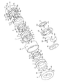
図1〜図6は本発明の実施例を示す図であり、そのうち、図1は光量調整装置の分解斜視図であり、図2は光量調整装置の断面図、図3〜図6はそのうちのモータの部分の部材の関係を示す断面図である。
【0022】
図1から図6において、1はロータを構成する円筒形状のマグネットであり、このロータであるマグネット1は、その外周表面を円周方向にn分割して〈本実施例では16分割して〉S極、N極が交互に着磁された着磁部1a,1b,1c,1d、1e,1f,1g,1h,1i,1j,1k,1m,1n,1p,1q,1rとすると、この着磁部1a,1c,1e,1g,1i,1k,1n,1qがS極に着磁され、着磁部1b,1d,1f,1h,1j,1m,1p,1rがN極に着磁されている。またマグネット1は射出成形により形成されるプラスチックマグネット材料により構成されている。これにより円筒形状の半径方向に関しての厚さは非常に薄く構成する事ができる。マグネット1はその内周面が外周面に比べ弱い着磁分布を持つかあるいはまったく着磁されていないかあるいは外周面と逆の極即ち外周面がS極の場合はその範囲の内周面はN極に着磁されているものである。
【0023】
またマグネット1には軸方向中央部に内径が小なるリブ部1sを備えている。該リブ部1sにはピン1tが設けられている。
【0024】
2は円筒形状のコイルであり、コイル2は前記マグネット1と同心でかつ、マグネット1を軸方向に重ねられた位置に配置され、コイル2はその外径が前記マグネット1の外径とほぼ同じ寸法である。
【0025】
18は軟磁性材料からなる第1のステータで、第1のステータは外筒および中空柱形状の内筒からなっている。第1のステータ18の外筒はその先端部にマグネット1の外周面に対向する(N/2−1)個即ち8個の第1の外側磁極18a,18b,18c,18d,18e,18f,18g,18hを形成している。また中空柱形状の内筒にはその先端部にマグネット1の内周面に対向する(N/2−1)個即ち8個の第1の内側磁極18i,18j,18k,18m,18n,18p,18q,18rを形成している。前記第1のステータの外側磁極18a,18b,18c,18d,18e,18f,18g,18hと第1の内側磁極18i,18j,18k,18m,18n,18p,18q,18rとはマグネット1を挟んでそれぞれ同位相になるように形成されており更に各磁極部は対向するマグネット1の着磁位相に対して同位相になるように360/〈n/2〉度の整数倍、即ち45度の整数倍ずれて形成されている。
【0026】
4は円筒形状のコイルであり、コイル4は前記マグネット1と同心でかつ、コイル2とによりマグネット1を軸方向に挟む位置に配置され、コイル4はその外径が前記マグネット1の外径とほぼ同じ寸法である。
【0027】
19は軟磁性材料からなる第2のステータで、第2のステータは外筒および中空柱形状の内筒からなっている。第2のステータ19の外筒はその先端部にマグネット1の外周面に対向する(N/2−1)個即ち8個の第2の外側磁極19a,19b,19c,19d,19e,19f,19g,19hを形成している。また中空柱形状の内筒にはその先端部にマグネット1の内周面に対向する(N/2−1)個即ち8個の第2の内側磁極19i,19j,19k,19m,19n,19p,19q,19rを形成している。前記第2のステータの外側磁極19a,19b,19c,19d,19e,19f,19g,19hと第2の内側磁極19i,19j,19k,19m,19n,19p,19q,19rとはマグネット1を挟んでそれぞれ同位相になるように形成されており更に各磁極部は対向するマグネット1の着磁位相に対して同位相になるように360/〈n/2〉度の整数倍、即ち45度の整数倍ずれて形成されている。
【0028】
第1のステータ18の外側磁極18a,18b,18c,18d,18e,18f,18g,18h 及び第2のステータ19の外側磁極19a,19b,19c,19d,19e,19f,19g,19h は切欠き穴と軸と平行方向に延出する歯により構成されている。この構成によりモータの直径を最小限にしつつ磁極の形成が可能となる。つまりもし、外側磁極を半径方向に延びる凹凸で形成するとその分モータの直径は大きくなってしまうのであるが、本実施例では切欠き穴と軸と平行方向に延出する歯により外側磁極を構成しているのでモータの直径を最小限に抑える事ができる。また第1のステータ18と第2のステータ19とでは、切欠き穴と軸と平行方向に延出する歯により構成されている外側磁極18a,18b,18c,18d,18e,18f,18g,18h 及び第2のステータ19の外側磁極19a,19b,19c,19d,19e,19f,19g,19h が向かい合って配置されているが第1のステータおよび第2のステータの位相は180/n度、即ち11.25°ずれて配置されている。
【0029】
第1のステータ18の外側磁極18a,18b,18c,18d,18e,18f,18g,18h および第1の内側磁極となる18i,18j,18k,18m,18n,18p,18q,18rはマグネット1の一端側の外周面および内周面に対向してマグネット1の一端側を挟み込むように形成されている。
【0030】
第2のステータ19の外側磁極19a,19b,19c,19d,19e,19f,19g,19h および第2の内側磁極となる19i,19j,19k,19m,19n,19p,19q,19rはマグネット1の他端側の外周面および内周面に対向してマグネット1の他端側を挟み込むように形成されている。
【0031】
第1のステータ18の外筒および内筒の間にコイル2が設けられ、このコイル2に通電される事により第1のステータ18の外側磁極18a,18b,18c,18d,18e,18f,18g,18h 及び内側磁極18i,18j,18k,18m,18n,18p,18q,18rとが励磁される。
【0032】
第2のステータ19の外筒および内筒の間にコイル4が設けられ、このコイル4に通電される事により第2のステータ19の外側磁極19a,19b,19c,19d,19e,19f,19g,19h 及び内側磁極19i,19j,19k,19m,19n,19p,19q,19rとが励磁される。
【0033】
したがって、コイル2により発生する磁束は外側磁極18a,18b,18c,18d,18e,18f,18g,18h 及び内側磁極18i,18j,18k,18m,18n,18p,18q,18rとの間のロータであるマグネット1を横切るので、効果的にロータであるマグネットに作用し、コイル3により発生する磁束は外側磁極19a,19b,19c,19d,19e,19f,19g,19h 及び内側磁極19i,19j,19k,19m,19n,19p,19q,19rとの間のロータであるマグネット1を横切るので、効果的にロータであるマグネットに作用しモータの出力を高める。
【0034】
また、マグネット1は前記したように射出成形により形成されるプラスチックマグネット材料により構成されており、これにより円筒形状の半径方向に関しての厚さは非常に薄く構成する事ができる。
【0035】
そのため第1のステータ18の外側磁極18a,18b,18c,18d,18e,18f,18g,18h と内側磁極18i,18j,18k,18m,18n,18p,18q,18rとの距離を非常に小さくできコイル4と第1のステータにより形成される磁気回路の磁気抵抗は小さく構成できる。また同様に第2のステータ19の外側磁極19a,19b,19c,19d,19e,19f,19g,19hと内側磁極19i,19j,19k,19m,19n,19p,19q,19rとの距離を非常に小さくできコイル5と第2のステータにより形成される磁気回路の磁気抵抗は小さく構成できる。これにより少ない電流で多くの磁束を発生させる事ができモータの出力アップ、低消費電力化、コイルの小型化が達成される事になる。
【0036】
20は非磁性材料の材料たとえばプラスチック材料やばね用ステンレス鋼やばね用リン青銅等からなる連結リングである。
【0037】
連結リング20は、第1のステータ18、第2のステータ19を、それらの位相を180/n度即ち11.25度ずらし且つ先端がある距離だけ間隔を隔てられた状態にて保持固定するためのものである。
【0038】
即ち第1のステータ18の外側磁極18a,18b,18c,18d,18e,18f,18g,18h の先端と第2のステータ19の外側磁極19a,19b,19c,19d,19e,19f,19g,19h の先端とが軸と並行方向にある距離離れ且つ回転方向の位置に関して位相を180/n度即ち11.25度ずらして向き合うように配置されている。
【0039】
連結リングは非磁性材料により構成した事により第1のステータ18と第2のステータ19とを磁気回路上分断でき、互いの影響が及ばないようにでき、モータの性能が安定する。
【0040】
21は第1の中空嵌合部材であり、第1のステータ18の内筒に固定され凸部21a,21b,21c,21d,21e,21f,21g,21hが内側磁極18i,18j,18k,18m,18n,18p,18q,18rの間から出っ張りマグネット1の内周部1uと摺動可能に嵌合する。また第1の中空嵌合部材21は中空構造となっている。
【0041】
22は第2の中空嵌合部材であり、第2のステータ19の内筒に固定され凸部22a,22b,22c,22d,22e,22f,22g,22hが内側磁極19i,19j,19k,19m,19n,19p,19q,19rの間から出っ張りマグネット1の内周部1vと摺動可能に嵌合する。また第21の中空嵌合部材22は中空構造となっている。
【0042】
またマグネット1のリブ部1sはスラスト方向に関して該第1の嵌合部材21と該第2の嵌合部材22とで規制されている。このような構造によりマグネット1は回転可能に保持されている。
【0043】
30は地板で、31は地板の嵌合部30Aと回転可能に取り付けられた出力リングである。地板には開口部30Dがある。
【0044】
出力リング31は穴31aがマグネット1のピン1tに嵌合しマグネット1の回転とともに回転する。この様子は後述する。
【0045】
32、33は絞り羽根であり、地板30に形成されたカム溝30A、30Bにダボ32A、33Aが摺動可能に嵌合し、且つ孔32B、33Bが出力リング31のダボ31B、31Cに回転可能に嵌合している。出力リング31の回転により絞り羽根32、33は光軸廻りに回転しつつ開口量を変化させるよう構成されている。34は羽根押さえ板であり地板30との間に絞り羽根32、33が移動可能な空間を保持し第1のステータ18の内径部に取り付けられている。
【0046】
上記構成において前記マグネットと前記第1或いは第2の内側磁極部に備えられた嵌合部材と摺動可能に嵌合する中空嵌合部を備えた事により中空円筒状のモータとする事ができ、またコイルにより発生する磁束は外側磁極と内側磁極との間にあるマグネットを横切るので効果的に作用するので出力が高いモータとなり半径方向に関しての厚さ寸法はマグネットの厚さと内側磁極と外側磁極の3つの合計でほぼ決められるので通常のマグネットの外側にコイルを配置するタイプのものや上記特開平09−331666等で記載されているタイプのモータに比較して半径方向の寸法が薄い円筒状のモータとなる。
【0047】
特開平09−331666等で記載されているタイプのモータの直径D1は少なくとも(マグネット厚さ+内側磁極+外側磁極)×2以上の寸法になる。これを光量調節装置に搭載する場合は上記説明した通り光量調節装置300の直径をD3は(2×D1+D2)となってしまうから(マグネット厚さ+内側磁極+外側磁極)×4+D2以上の寸法になってしまう。本発明の構成のモータを光量調整装置に使用する場合は中空部を光路として配置できるので概略(マグネット厚さ+内側磁極+外側磁極)×2+D2の寸法の光量調節装置で済む事になる。
【0048】
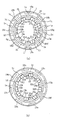
図2はステップモータの断面図であり、図3(a)、(b)、図4(a)、(b)、図5(a)、(b)、図6(a)、(b)のうち図3(a)、図4(a)、図5(a)、図6(a)、は図2のA−A線での断面図を示し図3(b)、図4(b)、図5(b)、図6(b)は図2のB−B線での断面図を示している。図3(a)と(b)とが同時点の断面図であり、図4(a)と(b)とが同時点の断面図であり、図5(a)と(b)とが同時点の断面図であり、図6(a)と(b)とが同時点の断面図である。図3、4、5、6ともに絞り羽根や出力リング等のモータの駆動動作の説明に不要なものは省略してある。
【0049】
次にステップモータの動作を説明する。
図3(a)と(b)の状態は第1のステータ18の第1の外側磁極18a,18b,18c,18d,18e,18f,18g,18hをN極、第1の内側磁極18i,18j,18k,18m,18n,18p,18q,18rをS極、第2のステータ19の第2の外側磁極19a,19b,19c,19d,19e,19f,19g,19hをS極、第2の内側磁極19i,19j,19k,19m,19n,19p,19q,19rをN極になるようにコイル2および4に通電した状態である。
【0050】
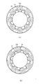
図3(a)と(b)の状態からコイル4への通電方向を切り替えて、第1のステータ18の第1の外側磁極18a,18b,18c,18d,18e,18f,18g,18hをN極とし、第1の内側磁極18i,18j,18k,18m,18n,18p,18q,18rをS極とし、第2のステータ19の第2の外側磁極19a,19b,19c,19d,19e,19f,19g,19hをN極とし第2の内側磁極19i,19j,19k,19m,19n,19p,19q,19rをS極に励磁すると、ロータであるマグネット1は反時計方向に11.25度回転し、図4(a)と(b)に示す状態になる。
【0051】
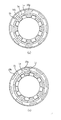
次に、コイル2への通電を反転させ、第1のステータ18の外側磁極18a,18b,18c,18d,18e,18f,18g,18hをS極とし、第1の補助ヨーク21からなる第1の内側磁極18i,18j,18k,18m,18n,18p,18q,18rをN極とし、第2のステータ19の外側磁極19a,19b,19c,19d,19e,19f,19g,19hをN極とし、第2の内側磁極19i,19j,19k,19m,19n,19p,19q,19rをS極に励磁すると、ロータであるマグネット1は更に反時計方向に11.25度回転し、図5(a)と(b)に示す状態になる。
【0052】
次にコイル4への通電を反転させ、第1のステータ18の外側磁極18a,18b,18c,18d,18e,18f,18g,18hをS極とし、第1の補助ヨーク21からなる第1の内側磁極18i,18j,18k,18m,18n,18p,18q,18rをN極とし、第2のステータ19の外側磁極19a,19b,19c,19d,19e,19f,19g,19hをS極とし、第2の内側磁極19i,19j,19k,19m,19n,19p,19q,19rをN極に励磁すると、ロータであるマグネット1は更に反時計方向に11.25度回転し、図6(a)と(b)に示す状態になる。
【0053】
以後このようにコイル2およびコイル4への通電方向を順次切り換えていくことによりロータであるマグネット1は通電位相に応じた位置へと回転していくものである。
【0054】
出力リング31は穴31aがマグネット1のピン1tに嵌合しマグネット1の回転とともに回転する構造になっているのでコイル2およびコイル4への通電方向を順次切り換えていくことにより順次回転していきその回転位置に応じた量だけ絞り羽根32、33を変位させ開口量を調節していくものである。
【0055】
ここで、このような構成のアクチエータが超小型化となる上で最適な構成である事について述べる。
【0056】
上記構成において前記マグネットと前記第1或いは第2の内側磁極部に備えられた嵌合部材と摺動可能に嵌合する中空嵌合部を備えた事により中空円筒状のモータとする事ができ、またコイルにより発生する磁束は外側磁極と内側磁極との間にあるマグネットを横切るので効果的に作用するので出力が高いモータとなる。さらに半径方向に関しての厚さ寸法はマグネットの厚さと内側磁極と外側磁極の3つの合計でほぼ決められるので通常のマグネットの外側にコイルを配置するタイプのものや上記特開平09−331666等で記載されているタイプのモータに比較して半径方向の寸法が薄い円筒状のモータとなる。特に外側磁極を切欠き穴と軸と平行方向に延出する歯により構成しているのでモータの直径を最小限に抑える事ができる。つまりもし、外側磁極を半径方向に延びる凹凸で形成するとその分モータの直径は大きくなってしまうのであるが、本実施例では切欠き穴と軸と平行方向に延出する歯により外側磁極を構成しているのでモータの直径を最小限に抑える事ができる。
【0057】
本発明の構成のモータを光量調整装置に使用する場合は中空部を光路として配置できるので概略(マグネット厚さ+内側磁極+外側磁極)×2+D2の寸法の光量調節装置で済む事になる。しかも外側磁極は切欠き穴と軸と平行方向に延出する歯により構成しているので非常にコンパクトなものになる。
【0058】
(実施例2)
図7は実施例2である。上記モータをレンズ鏡筒の駆動源として使用した例である。50は第1のステータ18に固定されたヘリコイド地板である。51はレンズホルダーでありオスヘリコイド部51aを備え、該オスヘリコイド部51aはヘリコイド地板50のメスヘリコイド部50aと摺動可能に嵌合しレンズホルダー51は回転することで軸方向に移動する。
【0059】
52はレンズでレンズホルダー51に固定され、レンズホルダー51は回転することで光軸方向に関しての位置が変位する。レンズホルダー51は溝50bを備えこの溝50bはマグネット1のピン1sと嵌合して回転方向に関してはマグネット1と一体的に回転し軸方向に関しての相対的な移動は可能になっている。つまりマグネット1が回転することでレンズは光軸方向の位置を変位する。レンズ1の光軸および光路は本中空形状のモータの中空部に配置してあるためコンパクトな鏡筒装置とすることができる。
【0060】
即ち上記構成において前記マグネットは前記第1或いは第2の内側磁極部に備えられた嵌合部材と摺動可能に嵌合する中空嵌合部を備えた事により中空円筒状のモータとする事ができ、コイルにより発生する磁束は外側磁極と内側磁極との間にあるマグネットを横切るので効果的に作用するので出力が高いモータとなり半径方向に関しての厚さ寸法はマグネットの厚さと内側磁極と外側磁極の3つの合計でほぼ決められるので通常のマグネットの外側にコイルを配置するタイプのものや上記特開平09−331666等で記載されているタイプのモータに比較して半径方向の寸法が薄い円筒状のモータとなる。
【0061】
特開平09−331666等で記載されているタイプのモータの直径D1は少なくとも(マグネット厚さ+内側磁極+外側磁極)×2以上の寸法になる。これを鏡筒装置に搭載する場合は上記説明した通り鏡筒装置300の直径をD3は(2×D1+D2)となってしまうから(マグネット厚さ+内側磁極+外側磁極)×4+D2以上の寸法になってしまう。本発明の構成のモータを使用する場合は中空部を光路として使うことができ概略(マグネット厚さ+内側磁極+外側磁極)×2+D2の寸法の鏡筒装置で済む事になる。
【0062】
【発明の効果】
以上詳記したように、本発明によれば、円筒形状に形成されるとともに少なくとも外周面が周方向に分割して異なる極に交互に着磁されたマグネットと、コイルが巻回された第1のボビンと、コイルが巻回された第2のボビンと、前記第1のボビンに巻回されたコイルにより励磁され前記マグネットの一端側の外周面に対向する第1の外側磁極部と、前記マグネットの内周面に対向し中空概略円筒形状の第1の内側磁極部と、前記第2のボビンに巻回されたコイルにより励磁され前記マグネットのもう一端側の外周面に対向する第2の外側磁極部とマグネットの内周面に対向し中空概略円筒形状の第2の内側磁極部を備え、前記マグネットは前記第1或いは第2の内側磁極部に備えられた嵌合部材と摺動可能に嵌合する中空嵌合部を備えた構造のモータとしたことにより中空円筒状のモータとする事ができ、コイルにより発生する磁束は外側磁極と内側磁極との間にあるマグネットを横切るので効果的に作用するので出力が高いモータとなる。半径方向に関しての厚さ寸法はマグネットの厚さと内側磁極と外側磁極の3つの合計でほぼ決められるので通常のマグネットの外側にコイルを配置するタイプのものや上記特開平09−331666等で記載されているタイプのモータに比較して半径方向の寸法が薄い円筒状のモータを提供する事ができる。
【0063】
特開平09−331666等で記載されているタイプのモータの直径D1は少なくとも(マグネット厚さ+内側磁極+外側磁極)×2以上の寸法になる。これを鏡筒地板に搭載する場合は上記説明した通り鏡筒地板300の直径をD3は(2×D1+D2)となってしまうから(マグネット厚さ+内側磁極+外側磁極)×4+D2以上の寸法になってしまう。本発明の構成のモータを使用する場合は概略(マグネット厚さ+内側磁極+外側磁極)×2+D2の寸法の鏡筒地板で済む事になる。つまり上記構成にする事で中空部を別の機能に使えるドーナツ型の半径方向に関しての厚さ寸法薄い高出力のモータを達成できる。
【0064】
また、このようなモータを光量調整装置やレンズ駆動装置の駆動源として用いモータの中空部を開口やレンズの光路となるように配置することによりコンパクトな光量調整装置やレンズ鏡筒となる。
【図面の簡単な説明】
【図1】図1は本発明に係る光量調整装置の分解斜視図である。
【図2】図2は図1に示す光量調整装置の断面図である。
【図3】図3はモータの部分の部材の関係を示す断面図である。
【図4】図4はモータの部分の部材の関係を示す断面図である。
【図5】図5はモータの部分の部材の関係を示す断面図である。
【図6】図6はモータの部分の部材の関係を示す断面図である。
【図7】図7は鏡筒の断面図である。
【図8】図8は従来のステップモータの断面図である。
【図9】図9は従来のステップモータのステータの様子を示す断面図である。
【図10】図10は従来のステップモータを配置した場合の鏡筒地板或いは光量調節装置の平面図である。
【符号の説明】
1 マグネット
2 コイル
4 コイル
18 第1のステータ
19 第2のステータ
20 連結リング
21 第1の中空嵌合部材
22 第2の中空嵌合部材
30 地板
31 出力リング
32 絞り羽根
33 絞り羽根
34 羽根押さえ板
50 ヘリコイド地板
51 レンズホルダー
52 レンズ[0001]
[Industrial application fields]
The present invention relates to an ultra-compact motor, a light amount adjusting device using the motor, and a lens barrel.
[0002]
[Prior art]
FIG. 8 shows a conventional small cylindrical step motor. A
[0003]
A
[0004]
However, the conventional small step motor shown in FIG. 8 has the disadvantage that the outer dimensions of the motor become large because the
[0005]
The present applicant has proposed a motor that solves such problems in Japanese Patent Laid-Open No. 09-331666. In this proposed motor, a rotor composed of permanent magnets that are equally divided in the circumferential direction and alternately magnetized to different poles is formed in a cylindrical shape, and the first coil, rotor, and second are formed in the axial direction of the rotor. Are arranged in order, the first outer magnetic pole and the first inner magnetic pole excited by the first coil are opposed to the outer peripheral surface and inner peripheral surface of the rotor, and the second coil excited by the second coil The outer magnetic pole and the second inner magnetic pole are configured to face the outer peripheral surface and the inner peripheral surface of the rotor, and the rotating shaft that is the rotor shaft is taken out from the cylindrical permanent magnet.
[0006]
The motor having such a configuration has a high output and can have a small external dimension, but it is desired to facilitate the joining of the rotor shaft and the permanent magnet. Furthermore, in the above configuration, by making the magnet thinner, the distance between the first outer magnetic pole and the first inner magnetic pole and the distance between the second outer magnetic pole and the second inner magnetic pole can be reduced as a result. Magnetic resistance can be reduced. According to this, it is possible to generate a large amount of magnetic flux with a small amount of current flowing through the first coil and the second coil.
[0007]
[Problems to be solved by the invention]
However, since the motor of the type described in the above Japanese Patent Application Laid-Open No. 09-331666 has a solid cylindrical shape, it is arranged so as to be parallel to the optical axis in the camera barrel and is used as an aperture blade, shutter, lens, etc. When the lens is used to drive the lens, the radius of the lens barrel is a value obtained by adding the diameter of the motor to the radius of the lens or the aperture aperture, and the diameter of the camera barrel is not sufficiently small. .
[0008]
This is shown in FIG. If the motor is M, the lens barrel base plate or the light quantity adjusting device is 300, the opening is 301, the diameter of the motor M is D1, the diameter of the
[0009]
In addition, those in which the diaphragm blades are driven by a hollow donut-shaped motor are proposed in, for example, Japanese Patent Laid-Open Nos. 53-37745 and 57-166847. Since these are coiled around the outside of the hollow magnet, the thickness of the coil, the thickness of the magnet, and the thickness of the stator are all added to the thickness in the radial direction, resulting in a thin donut shape with a radial thickness dimension. It was not enough as a motor.
[0010]
Further, a lens driving device is proposed in Japanese Utility Model Laid-Open No. 56-172827. This is because the center axis of the coil is arranged in the direction toward the center of the optical axis of the lens barrel, the coil shape becomes complicated and the assembly becomes complicated, the number of parts increases, and the device itself does not become compact. There was a problem that the number of coils increased and the cost increased.
[0011]
An object of the present invention is firstly to provide a cylindrical motor having a high output and thin in the radial direction.
[0012]
A second object of the present invention is to provide a compact (small diameter) light amount adjusting device.
[0013]
A third object of the present invention is to provide a compact (small diameter) lens barrel.
[0014]
[Means for Solving the Problems]
The motor of the present invention is formed in a cylindrical shape, and at least the outer peripheral surface is divided in the circumferential direction and alternately magnetized to different poles.A rib portion extending on the inner peripheral surface of the cylindrical shape is formed, and a pin engaging with the output member is formed on the rib portion.Magnets,A first outer magnetic pole portion facing the outer peripheral surface on one end side of the magnet is formed on the outer cylinder, and a first inner magnetic pole portion facing the inner peripheral surface on the one end side of the magnet is formed on the inner cylinder. The first stator having a double cylindrical shape and the outer cylinder and the inner cylinder of the first stator to excite the first outer magnetic pole part and the first inner magnetic pole part. A first coil and a convex portion that is fixed to the inner cylinder of the first stator and protrudes from between the first inner magnetic pole portions and slidably fits with an inner peripheral surface on one end side of the magnet. And a second outer magnetic pole portion facing the outer peripheral surface on the other end side of the magnet is formed on the outer cylinder and faces the inner peripheral surface on the other end side of the magnet. A second cylindrical second stator having a second inner magnetic pole portion formed on the inner cylinder; A second coil that is disposed between the outer cylinder and the inner cylinder of the second stator and excites the second outer magnetic pole part and the second inner magnetic pole part, and the inner part of the second stator. A second hollow fitting member that is fixed to the cylinder and protrudes from between the second inner magnetic pole portions and has a convex portion that is slidably fitted to the inner peripheral surface of the other end side of the magnet. The magnet is regulated in the axial direction by sandwiching a rib portion of the magnet between the first hollow fitting member and the second hollow fitting member.
[0015]
In the above configuration, the magnet can be formed into a hollow cylindrical motor by including a hollow fitting portion that is slidably fitted to a fitting member provided in the first or second inner magnetic pole portion. Since the magnetic flux generated by the coil crosses the magnet between the outer magnetic pole and the inner magnetic pole, it works effectively, so the motor becomes a high output and the thickness dimension in the radial direction is the thickness of the magnet and the inner and outer magnetic poles. Since the total of the three is almost determined, a cylindrical shape whose radial dimension is thinner than that of a motor in which a coil is arranged outside a normal magnet or a motor of the type described in the above-mentioned Japanese Patent Application Laid-Open No. 09-331666 or the like. A motor can be provided. The diameter D1 of a motor of the type described in Japanese Patent Application Laid-Open No. 09-331666 is at least (magnet thickness + inner magnetic pole + outer magnetic pole) × 2 or more.
[0016]
When this is mounted on the lens barrel base plate, as described above, the diameter of the lens
[0021]
【Example】
Example 1
1 to 6 are diagrams showing an embodiment of the present invention, in which FIG. 1 is an exploded perspective view of a light amount adjusting device, FIG. 2 is a sectional view of the light amount adjusting device, and FIGS. It is sectional drawing which shows the relationship of the member of the part of a motor.
[0022]
In FIG. 1 to FIG. 6, reference numeral 1 denotes a cylindrical magnet constituting the rotor. The magnet 1 as the rotor is divided into n in the circumferential direction on the outer peripheral surface (in this embodiment, divided into 16). When the
[0023]
Further, the magnet 1 is provided with a
[0024]
[0025]
[0026]
Reference numeral 4 denotes a cylindrical coil. The coil 4 is concentric with the magnet 1 and disposed at a position sandwiching the magnet 1 in the axial direction by the
[0027]
[0028]
The outer
[0029]
The outer
[0030]
The outer
[0031]
The
[0032]
The coil 4 is provided between the outer cylinder and the inner cylinder of the
[0033]
Therefore, the magnetic flux generated by the
[0034]
Moreover, the magnet 1 is comprised by the plastic magnet material formed by injection molding as mentioned above, By this, the thickness regarding the radial direction of a cylindrical shape can be comprised very thinly.
[0035]
Therefore, the distance between the outer
[0036]
[0037]
The
[0038]
That is, the tips of the outer
[0039]
Since the connecting ring is made of a nonmagnetic material, the
[0040]
A first hollow fitting
[0041]
[0042]
Further, the
[0043]
[0044]
The
[0045]
[0046]
In the above configuration, a hollow cylindrical motor can be obtained by providing a hollow fitting portion that is slidably fitted to the magnet and the fitting member provided in the first or second inner magnetic pole portion. Also, since the magnetic flux generated by the coil crosses the magnet between the outer magnetic pole and the inner magnetic pole, it acts effectively, so that the motor becomes a high output and the thickness dimension in the radial direction is the thickness of the magnet, the inner magnetic pole and the outer magnetic pole. Therefore, the radial dimension is thinner than that of a motor in which a coil is arranged outside a normal magnet or a motor of the type described in JP-A 09-331666. It becomes a motor.
[0047]
The diameter D1 of a motor of the type described in Japanese Patent Application Laid-Open No. 09-331666 is at least (magnet thickness + inner magnetic pole + outer magnetic pole) × 2 or more. When this is mounted on the light amount adjusting device, the diameter D3 of the light
[0048]
FIG. 2 is a cross-sectional view of the step motor. FIGS. 3A, 3B, 4A, 4B, 5A, 5B, 6A, 6B. 3 (a), FIG. 4 (a), FIG. 5 (a), and FIG. 6 (a) are sectional views taken along the line AA in FIG. 2, and FIG. 3 (b) and FIG. 5 (b) and FIG. 6 (b) are sectional views taken along line BB in FIG. 3 (a) and 3 (b) are cross-sectional views at the same point, FIGS. 4 (a) and 4 (b) are cross-sectional views at the same point, and FIGS. 5 (a) and 5 (b) are the same. It is sectional drawing of a point, FIG. 6 (a) and (b) are sectional drawings of a simultaneous point. In FIGS. 3, 4, 5, and 6, unnecessary parts for explanation of the driving operation of the motor such as the diaphragm blades and the output ring are omitted.
[0049]
Next, the operation of the step motor will be described.
3 (a) and 3 (b) show that the first outer
[0050]
3 (a) and 3 (b), the energization direction to the coil 4 is switched, and the first outer
[0051]
Next, the energization of the
[0052]
Next, the energization of the coil 4 is reversed, and the outer
[0053]
Thereafter, by sequentially switching the energization directions to the
[0054]
Since the
[0055]
Here, it will be described that an actuator having such a configuration is optimal for miniaturization.
[0056]
In the above configuration, a hollow cylindrical motor can be obtained by providing a hollow fitting portion that is slidably fitted to the magnet and the fitting member provided in the first or second inner magnetic pole portion. Further, since the magnetic flux generated by the coil crosses the magnet between the outer magnetic pole and the inner magnetic pole, it acts effectively, so that the motor has a high output. Further, since the thickness dimension in the radial direction is substantially determined by the total thickness of the magnet and the inner and outer magnetic poles, a type in which a coil is arranged outside a normal magnet or the above-mentioned JP-A 09-331666 is described. A cylindrical motor having a smaller radial dimension than a motor of the type that is used. In particular, since the outer magnetic pole is constituted by a notch hole and a tooth extending in a direction parallel to the shaft, the diameter of the motor can be minimized. In other words, if the outer magnetic pole is formed with irregularities extending in the radial direction, the diameter of the motor increases accordingly, but in this embodiment, the outer magnetic pole is constituted by the notch hole and the tooth extending in the direction parallel to the axis. As a result, the motor diameter can be minimized.
[0057]
When the motor having the configuration of the present invention is used in the light amount adjusting device, the hollow portion can be arranged as an optical path, so that a light amount adjusting device having dimensions of (magnet thickness + inner magnetic pole + outer magnetic pole) × 2 + D2 is sufficient. Moreover, since the outer magnetic pole is constituted by a notch hole and a tooth extending in a direction parallel to the axis, the outer magnetic pole becomes very compact.
[0058]
(Example 2)
FIG. 7 shows a second embodiment. This is an example in which the motor is used as a driving source for a lens barrel.
[0059]
A
[0060]
That is, in the above configuration, the magnet may be a hollow cylindrical motor by including a hollow fitting portion that slidably fits with a fitting member provided in the first or second inner magnetic pole portion. Since the magnetic flux generated by the coil crosses the magnet between the outer magnetic pole and the inner magnetic pole, it works effectively, so the motor becomes a high output and the thickness dimension in the radial direction is the thickness of the magnet, the inner magnetic pole and the outer magnetic pole. Therefore, the radial dimension is thinner than that of a motor in which a coil is arranged outside a normal magnet or a motor of the type described in JP-A 09-331666. It becomes a motor.
[0061]
The diameter D1 of a motor of the type described in Japanese Patent Application Laid-Open No. 09-331666 is at least (magnet thickness + inner magnetic pole + outer magnetic pole) × 2 or more. When this is mounted on the lens barrel device, the diameter D3 of the
[0062]
【The invention's effect】
As described above in detail, according to the present invention, a magnet that is formed in a cylindrical shape and at least an outer peripheral surface is divided in the circumferential direction and is alternately magnetized to different poles, and a first coil wound with a coil. A second bobbin around which a coil is wound, a first outer magnetic pole portion that is excited by a coil wound around the first bobbin and faces an outer peripheral surface on one end side of the magnet, A second inner magnetic pole portion opposed to the inner peripheral surface of the magnet and excited by a coil wound around the second bobbin and having a hollow substantially cylindrical shape, is opposed to the outer peripheral surface on the other end side of the magnet. Opposed to the outer magnetic pole part and the inner peripheral surface of the magnet is provided with a hollow inner cylindrical second inner magnetic pole part, and the magnet is slidable with a fitting member provided in the first or second inner magnetic pole part. With a hollow fitting part The motor and then can be a hollow cylindrical motor by the magnetic flux generated by the coil is output because they act effectively traverses the magnet present between the outer magnetic pole and the inner magnetic pole is higher motor. Since the thickness dimension in the radial direction is almost determined by the total thickness of the magnet and the inner and outer magnetic poles, it is described in a type in which a coil is arranged outside a normal magnet or the above-mentioned JP-A 09-331666. It is possible to provide a cylindrical motor having a thin radial dimension compared to the type of motor.
[0063]
The diameter D1 of a motor of the type described in Japanese Patent Application Laid-Open No. 09-331666 is at least (magnet thickness + inner magnetic pole + outer magnetic pole) × 2 or more. When this is mounted on the lens barrel base plate, the diameter of the lens
[0064]
Further, by using such a motor as a drive source of the light amount adjusting device or the lens driving device and arranging the hollow portion of the motor so as to be an opening or an optical path of the lens, a compact light amount adjusting device or a lens barrel can be obtained.
[Brief description of the drawings]
FIG. 1 is an exploded perspective view of a light amount adjusting apparatus according to the present invention.
FIG. 2 is a cross-sectional view of the light amount adjusting device shown in FIG.
FIG. 3 is a cross-sectional view showing the relationship of members of a motor portion.
FIG. 4 is a cross-sectional view showing a relationship of members of a motor portion.
FIG. 5 is a cross-sectional view showing a relationship of members of a motor portion.
FIG. 6 is a cross-sectional view showing a relationship of members of a motor portion.
FIG. 7 is a cross-sectional view of a lens barrel.
FIG. 8 is a cross-sectional view of a conventional step motor.
FIG. 9 is a sectional view showing a state of a stator of a conventional step motor.
FIG. 10 is a plan view of a lens barrel base plate or a light amount adjusting device when a conventional step motor is arranged.
[Explanation of symbols]
1 Magnet
2 coils
4 Coils
18 First stator
19 Second stator
20 Connecting ring
21 First hollow fitting member
22 Second hollow fitting member
30 ground plane
31 Output ring
32 Aperture blade
33 Aperture blade
34 Blade holding plate
50 Helicoid ground plane
51 Lens holder
52 lenses
Claims (3)
前記マグネットの一方端側の外周面に対向する第1の外側磁極部が外筒に形成され、前記マグネットの一方端側の内周面に対向する第1の内側磁極部が内筒に形成される二重円筒形状の第1のステータと、
前記第1のステータの前記外筒と前記内筒との間に配置され、前記第1の外側磁極部および前記第1の内側磁極部を励磁する第1のコイルと、
前記第1のステータの前記内筒に固定され、前記第1の内側磁極部の間から出っ張り前記マグネットの一方端側の内周面と摺動可能に嵌合する凸部が形成される第1の中空嵌合部材と、
前記マグネットの他方端側の外周面に対向する第2の外側磁極部が外筒に形成され、前記マグネットの他方端側の内周面に対向する第2の内側磁極部が内筒に形成される二重円筒形状の第2のステータと、
前記第2のステータの前記外筒と前記内筒との間に配置され、前記第2の外側磁極部および前記第2の内側磁極部を励磁する第2のコイルと、
前記第2のステータの前記内筒に固定され、前記第2の内側磁極部の間から出っ張り前記マグネットの他方端側の内周面と摺動可能に嵌合する凸部が形成される第2の中空嵌合部材とを備え、
前記第1の中空嵌合部材と前記第2の中空嵌合部材とで前記マグネットのリブ部を挟み込むことで、前記マグネットを軸方向に規制することを特徴とするモータ。 It is formed in a cylindrical shape, and at least the outer peripheral surface is divided in the circumferential direction and is alternately magnetized to different poles, and a rib portion extending to the inner peripheral surface of the cylindrical shape is formed. A magnet on which an engaging pin is formed ;
A first outer magnetic pole portion facing the outer peripheral surface on one end side of the magnet is formed on the outer cylinder, and a first inner magnetic pole portion facing the inner peripheral surface on the one end side of the magnet is formed on the inner cylinder. A double cylindrical first stator,
A first coil that is disposed between the outer cylinder and the inner cylinder of the first stator and that excites the first outer magnetic pole part and the first inner magnetic pole part;
A first protrusion is formed which is fixed to the inner cylinder of the first stator and protrudes from between the first inner magnetic pole portions and slidably fits with an inner peripheral surface on one end side of the magnet. A hollow fitting member of
A second outer magnetic pole portion facing the outer peripheral surface on the other end side of the magnet is formed on the outer cylinder, and a second inner magnetic pole portion facing the inner peripheral surface on the other end side of the magnet is formed on the inner cylinder. A double cylindrical second stator,
A second coil that is disposed between the outer cylinder and the inner cylinder of the second stator and that excites the second outer magnetic pole part and the second inner magnetic pole part;
A second protrusion is formed that is fixed to the inner cylinder of the second stator and protrudes from between the second inner magnetic pole portions and slidably fits with the inner peripheral surface of the other end side of the magnet. A hollow fitting member,
The motor is characterized in that the magnet is restricted in the axial direction by sandwiching a rib portion of the magnet between the first hollow fitting member and the second hollow fitting member.
Priority Applications (3)
| Application Number | Priority Date | Filing Date | Title |
|---|---|---|---|
| JP2000228087A JP4378039B2 (en) | 2000-07-28 | 2000-07-28 | Motor, light amount adjusting device, and lens barrel |
| US09/910,046 US6798093B2 (en) | 2000-07-28 | 2001-07-23 | Dual coil permanent magnet motor having inner annular member |
| US10/434,060 US6800970B2 (en) | 2000-07-28 | 2003-05-09 | Motor and optical apparatus using the same |
Applications Claiming Priority (1)
| Application Number | Priority Date | Filing Date | Title |
|---|---|---|---|
| JP2000228087A JP4378039B2 (en) | 2000-07-28 | 2000-07-28 | Motor, light amount adjusting device, and lens barrel |
Publications (3)
| Publication Number | Publication Date |
|---|---|
| JP2002051524A JP2002051524A (en) | 2002-02-15 |
| JP2002051524A5 JP2002051524A5 (en) | 2007-08-23 |
| JP4378039B2 true JP4378039B2 (en) | 2009-12-02 |
Family
ID=18721446
Family Applications (1)
| Application Number | Title | Priority Date | Filing Date |
|---|---|---|---|
| JP2000228087A Expired - Fee Related JP4378039B2 (en) | 2000-07-28 | 2000-07-28 | Motor, light amount adjusting device, and lens barrel |
Country Status (1)
| Country | Link |
|---|---|
| JP (1) | JP4378039B2 (en) |
Families Citing this family (6)
| Publication number | Priority date | Publication date | Assignee | Title |
|---|---|---|---|---|
| JP3950756B2 (en) | 2002-07-10 | 2007-08-01 | キヤノン株式会社 | Driving device and light amount adjusting device |
| JP4164297B2 (en) | 2002-07-11 | 2008-10-15 | キヤノン株式会社 | Driving device, light amount adjusting device, and lens driving device |
| JP2005234210A (en) * | 2004-02-19 | 2005-09-02 | Alps Electric Co Ltd | Lens moving mechanism |
| JP4681874B2 (en) | 2004-12-24 | 2011-05-11 | キヤノン株式会社 | Drive device |
| JP4669436B2 (en) * | 2006-04-27 | 2011-04-13 | キヤノン株式会社 | Lens barrel drive |
| JP6051033B2 (en) * | 2012-12-17 | 2016-12-21 | キヤノン電子株式会社 | Light amount adjusting device and optical apparatus |
-
2000
- 2000-07-28 JP JP2000228087A patent/JP4378039B2/en not_active Expired - Fee Related
Also Published As
| Publication number | Publication date |
|---|---|
| JP2002051524A (en) | 2002-02-15 |
Similar Documents
| Publication | Publication Date | Title |
|---|---|---|
| US6800970B2 (en) | Motor and optical apparatus using the same | |
| US7122920B2 (en) | Motor and optical apparatus | |
| JP4012170B2 (en) | Actuator and light quantity adjusting device | |
| US6591066B2 (en) | Motor and photographing apparatus | |
| KR100550140B1 (en) | Motor | |
| JP4378039B2 (en) | Motor, light amount adjusting device, and lens barrel | |
| JP4497884B2 (en) | Drive device | |
| JP4289759B2 (en) | Drive transmission device and diaphragm blade drive device using the drive transmission device | |
| JP3697179B2 (en) | motor | |
| JP3907478B2 (en) | motor | |
| JP4378248B2 (en) | Stepping motor | |
| JP4378047B2 (en) | motor | |
| JP2003189585A (en) | Motor and optical device | |
| JP2002051526A (en) | Motor | |
| JP4272948B2 (en) | Stepping motor | |
| JP5171067B2 (en) | Driving device and light amount adjusting device | |
| JP4250312B2 (en) | Drive transmission device | |
| JP2003219623A (en) | Stepping motor | |
| JP4324002B2 (en) | Stepping motor | |
| JP2003088085A (en) | Motor | |
| JPH1075558A (en) | Motor | |
| JP2001346373A (en) | Motor | |
| JP2002142429A (en) | Motor | |
| JPH1127924A (en) | Motor | |
| JP2004064847A (en) | Motor and optical instrument |
Legal Events
| Date | Code | Title | Description |
|---|---|---|---|
| A521 | Written amendment |
Free format text: JAPANESE INTERMEDIATE CODE: A523 Effective date: 20070705 |
|
| A621 | Written request for application examination |
Free format text: JAPANESE INTERMEDIATE CODE: A621 Effective date: 20070705 |
|
| A977 | Report on retrieval |
Free format text: JAPANESE INTERMEDIATE CODE: A971007 Effective date: 20090507 |
|
| A131 | Notification of reasons for refusal |
Free format text: JAPANESE INTERMEDIATE CODE: A131 Effective date: 20090519 |
|
| A521 | Written amendment |
Free format text: JAPANESE INTERMEDIATE CODE: A523 Effective date: 20090714 |
|
| TRDD | Decision of grant or rejection written | ||
| A01 | Written decision to grant a patent or to grant a registration (utility model) |
Free format text: JAPANESE INTERMEDIATE CODE: A01 Effective date: 20090908 |
|
| A01 | Written decision to grant a patent or to grant a registration (utility model) |
Free format text: JAPANESE INTERMEDIATE CODE: A01 |
|
| A61 | First payment of annual fees (during grant procedure) |
Free format text: JAPANESE INTERMEDIATE CODE: A61 Effective date: 20090914 |
|
| R150 | Certificate of patent or registration of utility model |
Free format text: JAPANESE INTERMEDIATE CODE: R150 |
|
| FPAY | Renewal fee payment (event date is renewal date of database) |
Free format text: PAYMENT UNTIL: 20120918 Year of fee payment: 3 |
|
| FPAY | Renewal fee payment (event date is renewal date of database) |
Free format text: PAYMENT UNTIL: 20120918 Year of fee payment: 3 |
|
| FPAY | Renewal fee payment (event date is renewal date of database) |
Free format text: PAYMENT UNTIL: 20130918 Year of fee payment: 4 |
|
| LAPS | Cancellation because of no payment of annual fees |