JP4377841B2 - Method for adjusting focus detection means or tracking detection means and optical disc apparatus - Google Patents
Method for adjusting focus detection means or tracking detection means and optical disc apparatus Download PDFInfo
- Publication number
- JP4377841B2 JP4377841B2 JP2005119173A JP2005119173A JP4377841B2 JP 4377841 B2 JP4377841 B2 JP 4377841B2 JP 2005119173 A JP2005119173 A JP 2005119173A JP 2005119173 A JP2005119173 A JP 2005119173A JP 4377841 B2 JP4377841 B2 JP 4377841B2
- Authority
- JP
- Japan
- Prior art keywords
- error signal
- spherical aberration
- signal
- focus
- tracking
- Prior art date
- Legal status (The legal status is an assumption and is not a legal conclusion. Google has not performed a legal analysis and makes no representation as to the accuracy of the status listed.)
- Expired - Fee Related
Links
Images


Description
本発明は、フォーカス検出手段またはトラッキング検出手段の調整方法および光ディスク装置に関する。 The present invention relates to a method for adjusting focus detection means or tracking detection means, and an optical disc apparatus.
今日では、追記型や書き換え型の光ディスク装置が広く普及している。これらの装置で用いられる光ディスク上には微少なトラックがスパイラル状または同心円状に設けられており、これらのトラック上に情報が記録される。トラックに情報記録するまたはトラックから情報を読み出すためには、光ビームが常に情報トラック上に位置するように制御する必要がある。 Today, write-once and rewritable optical disk devices are widely used. On an optical disk used in these apparatuses, minute tracks are provided spirally or concentrically, and information is recorded on these tracks. In order to record information on a track or read information from a track, it is necessary to control so that the light beam is always positioned on the information track.
また、光ディスクの面ぶれ、ターンテーブルの回転軸の軸ぶれなどによる記録面に対するレーザービームのぶれを補正し、光ディスクの記録面上に精度良くレーザービームの集光点を追従させる必要がある。
図23は従来の光ディスク装置の構成を示した図である。図23の光照射部3は、光ビーム2を光ディスク1に向け所定のパワーで照射する。照射された光ビーム2は、ビームスプリッタ5を通過し、収束レンズ4によって光ディスク1の情報面上に収束される。光ディスク1によって反射した光ビーム2は、ビームスプリッタ5により受光部6に照射される。受光部6は、受光した光量を信号として出力する。光ヘッド7は、光照射部3と収束レンズ4とビームスプリッタ5と受光部6から構成される。フォーカスエラー検出部10は、受光部6の信号に基づきフォーカスエラー信号(以下FE信号と称す)を検出する。FE信号は、光スポットの焦点位置と光ディスクの情報信号記録面とのずれを表している。総受光量検出部12は、受光部6の信号に基づき反射光総和信号(以下、AS信号と称す)を検出する。補正係数演算部13は、FE信号振幅と総受光量の比である補正係数を演算する。自動振幅制御部(AGC回路)14は、総受光量が変化すると、その変化量および補正係数からFE信号の振幅を自動で制御する。具体的には、自動振幅制御部14は、FE信号をAS信号で除算した値に基本利得をかけた値を出力する。これによって、ディスクの反射率が変化したり、光ビームのパワーがばらついてもFE信号振幅は所定の振幅に保たれる。これは、一般に、FE信号とAS信号はともにディスクからの反射光の強度に比例するためである。
In addition, it is necessary to correct the laser beam shake on the recording surface due to the optical disc surface shake, the rotational axis rotation of the turntable, and the like so that the condensing point of the laser beam follows the recording surface of the optical disc with high accuracy.
FIG. 23 is a diagram showing a configuration of a conventional optical disc apparatus. 23 emits the
またトラッキングエラー検出部11も、受光部6の信号に基づきトラッキングエラー信号(以下TE信号と称す)を検出する。TE信号は、ピットに対する光ピックアップのトラック幅方向位置ずれ情報である。FE信号の場合と同様に、総受光量検出部12は、受光部6の信号に基づき総受光量を検出し、補正係数演算部13は、TE信号振幅と総受光量の比である補正係数を演算する。自動振幅制御部14は、総受光量が変化すると、その変化量および補正係数からTE信号の振幅を自動で制御する。よってディスクの反射率や光ビームのパワーがばらついても、TE信号振幅は所定の振幅に保たれる。これは、一般に、TE信号とAS信号は、ともにディスクからの反射光の強度に比例するからである。
The tracking
さらに、光ディスクからの反射光量レベルがトラック間や記録層間によって変化する場合においても、FE信号やTE信号の振幅を調整する装置が提案されている(例えば、特許文献1を参照。)。
また、球面収差によってもFE信号に変化が生ずることに着目して、フォーカシング引き込み前に球面収差を付与することで、FE信号のS字曲線の傾斜を高め、その振幅を大きくすることができ、確実なフォーカス引き込みができるようにした装置も提案されている(例えば、特許文献2を参照。)。
In addition, paying attention to the fact that the FE signal also changes due to the spherical aberration, by adding the spherical aberration before focusing, the slope of the S-shaped curve of the FE signal can be increased and the amplitude thereof can be increased. There has also been proposed an apparatus that enables reliable focus pull-in (see, for example, Patent Document 2).
最近、開発されている405nm付近の青色レーザを用いた高密度の光ディスク装置においては、波長が短いために、ディスクチルトに起因する光ディスク上のスポットに発生するコマ収差が大きくなり、例えばDVDの赤色レーザに比べると、およそ1.6倍のコマ収差が発生する。さらに青色レーザに加え、ビームを絞るためNA=0.85のような大きな対物レンズを用いると、光透過層厚のばらつきに起因する光ディスク上のスポットに発生する球面収差が大きくなり、例えばDVDのようなNA=0.6のレンズに比べると、およそ10倍になる。 In a recently developed high-density optical disk apparatus using a blue laser of around 405 nm, the coma aberration generated in a spot on the optical disk due to the disk tilt increases due to the short wavelength. The coma aberration is about 1.6 times that of the laser. Further, when a large objective lens such as NA = 0.85 is used to narrow the beam in addition to the blue laser, the spherical aberration generated in the spot on the optical disk due to the variation in the thickness of the light transmission layer increases. Compared to such a lens with NA = 0.6, the magnification is about 10 times.
球面収差は、光ディスクの実際の光透過層厚が、光ヘッドを設計する際に前提とした基準となる理想の光透過層厚からずれることによって生じる。図20および図21に示すように、光ディスク上の光スポットに収差が発生すると、FE信号やTE信号は検出感度(すなわち、振幅や傾き)が変化するが、AS信号のレベルはほとんど変化しない。したがって従来のように除算回路等で自動振幅制御部(AGC回路)を構成している場合は、フォーカス、トラッキングAGCの各出力のレベルが変動し、フォーカス制御系やトラッキング制御系のゲインが変動する。一般的には、感度や振幅が下がるのでゲインが低下してしまい、最悪の場合は、自動振幅制御部(AGC回路)を動作させた状態でフォーカス制御やトラッキング制御がはずれてしまう。逆にフォーカス、トラッキングのループゲインを調整した後、球面収差が略0になるように補正すると、ゲインが高くなり制御系が発振するという課題があった。また、球面収差だけでなく、コマ収差においても光学系の構成や発生するコマ収差の方向や量、位相によっては上記球面収差と同様の課題が発生する
さらに球面収差が小さい状態でフォーカスエラー信号、トラッキングエラー信号の振幅調整やループゲイン調整がなされても、2層ディスク(あるいは多層ディスク)において、層間を移動した直後は光透過層厚みの差分の大きな球面収差が常に発生し、その発生した球面収差に球面収差補正素子が追従するまでは、フォーカス、トラッキングのゲインが低下し、移動先の層の情報面でフォーカス、トラッキング制御がはずれるという課題があった。
Spherical aberration occurs when the actual light transmission layer thickness of the optical disc deviates from the ideal light transmission layer thickness, which is a standard used when designing an optical head. As shown in FIGS. 20 and 21, when an aberration occurs in the light spot on the optical disk, the detection sensitivity (that is, amplitude and inclination) of the FE signal and TE signal changes, but the level of the AS signal hardly changes. Therefore, when the automatic amplitude control unit (AGC circuit) is configured by a divider circuit or the like as in the prior art, the output levels of the focus and tracking AGC vary, and the gains of the focus control system and tracking control system vary. . In general, the sensitivity and amplitude decrease, resulting in a decrease in gain. In the worst case, focus control and tracking control are lost while the automatic amplitude control unit (AGC circuit) is operated. Conversely, if the focus and tracking loop gains are adjusted and then corrected so that the spherical aberration becomes substantially zero, there is a problem that the gain increases and the control system oscillates. Further, not only spherical aberration but also coma aberration, the same problem as the above spherical aberration occurs depending on the configuration of the optical system and the direction, amount and phase of the coma aberration generated. Even when the amplitude of the tracking error signal or the loop gain is adjusted, a spherical aberration with a large difference in the thickness of the light transmission layer always occurs in the two-layer disc (or multilayer disc) immediately after moving between the layers. Until the spherical aberration correction element follows the aberration, there is a problem that the focus and tracking gains decrease, and the focus and tracking control is lost on the information surface of the destination layer.
そこで本発明は、上記課題に鑑み、球面収差、コマ収差が発生しても常に安定なフォーカス、トラッキング性能を確保できる自動振幅制御を可能とし、さらに2層ディスク、多層ディスクにおいても安定な高機能かつ信頼性の高い光ディスク装置を提供することを目的とする。 Therefore, in view of the above problems, the present invention enables automatic amplitude control that can always ensure stable focus and tracking performance even when spherical aberration and coma aberration occur, and is also stable and highly functional in two-layer discs and multilayer discs. An object of the present invention is to provide a highly reliable optical disc apparatus.
本発明に係るフォーカス検出手段またはトラッキング検出手段の調整方法は、光透過層を表面コートした情報担体の情報面に光ビームを照射し、記録再生を行う光ディスク装置であって、光ビームに発生している球面収差またはコマ収差を予め補正する収差補正手段と、フォーカスエラー信号またはトラッキングエラー信号を検出する検出手段とを備えた装置に用いられる。収差補正手段により球面収差量またはコマ収差量を所定の量に合致させた後、フォーカス検出手段またはトラッキング検出手段の信号振幅が所定値になるように調整する。 An adjustment method of a focus detection means or a tracking detection means according to the present invention is an optical disc apparatus that performs recording and reproduction by irradiating a light beam onto an information surface of an information carrier whose surface is coated with a light transmission layer, and is generated in the light beam. Used in an apparatus including aberration correction means for correcting spherical aberration or coma aberration in advance and detection means for detecting a focus error signal or tracking error signal. After the spherical aberration amount or the coma aberration amount is matched with a predetermined amount by the aberration correction unit, the signal amplitude of the focus detection unit or tracking detection unit is adjusted to a predetermined value.
本発明に係る光ディスク装置は、光透過層を表面コートした情報担体の情報面に光ビームを照射し、記録再生を行う光ディスク装置であって、光ビームに発生している球面収差またはコマ収差を予め補正する収差補正手段と、フォーカスエラー信号またはトラキングエラー信号を検出する検出手段と、収差補正手段により球面収差量またはコマ収差量を所定量に合致させた後、検出手段の信号振幅が所定値になるように調整する振幅調整手段とを備えている。 An optical disk apparatus according to the present invention is an optical disk apparatus for performing recording and reproduction by irradiating a light beam onto an information surface of an information carrier whose surface is coated with a light-transmitting layer, and to prevent spherical aberration or coma generated in the light beam. Aberration correction means for correcting in advance, detection means for detecting a focus error signal or tracking error signal, and after the spherical aberration amount or coma aberration amount is matched with a predetermined amount by the aberration correction means, the signal amplitude of the detection means is predetermined. Amplitude adjusting means for adjusting to a value.
本発明に係る光ディスク装置は、光透過層を表面コートした情報担体の情報面に光ビームを照射し、記録再生を行う光ディスク装置であって、光ビームに発生している球面収差またはコマ収差を予め補正する収差補正手段と、フォーカスエラー信号またはトラッキングエラー信号を検出する検出手段と、光ディスクからの全光量に対応した信号を検出する全光量検出手段と、全光量検出手段の信号に基づき検出手段の振幅を所定値になるように制御する振幅制御手段とを備えている。装置の起動時に収差補正手段で補正した後、振幅制御手段を動作させることを特徴とする。 An optical disk apparatus according to the present invention is an optical disk apparatus for performing recording and reproduction by irradiating a light beam onto an information surface of an information carrier whose surface is coated with a light-transmitting layer, and to prevent spherical aberration or coma generated in the light beam. Aberration correction means for correcting in advance, detection means for detecting a focus error signal or tracking error signal, total light quantity detection means for detecting a signal corresponding to the total light quantity from the optical disk, and detection means based on the signal of the total light quantity detection means Amplitude control means for controlling the amplitude of the signal so as to become a predetermined value. The amplitude control means is operated after correction by the aberration correction means when the apparatus is started.
本発明に係る光ディスク装置は、光透過層を表面コートした情報担体の情報面に光ビームを照射し、記録再生を行う光ディスク装置であって、光ビームに発生している球面収差またはコマ収差を予め補正する収差補正手段と、フォーカスエラー信号またはトラッキングエラー信号を検出する検出手段と、検出手段の信号に基づき情報面における光ビームが所定の状態になるように制御する制御手段と、制御手段のループゲインを計測調整するゲイン調整手段とを備えている。装置の起動時に収差補正手段で補正した後、ゲイン調整手段を動作させることを特徴とする。 An optical disk apparatus according to the present invention is an optical disk apparatus for performing recording and reproduction by irradiating a light beam onto an information surface of an information carrier whose surface is coated with a light-transmitting layer, and to prevent spherical aberration or coma generated in the light beam. An aberration correcting means for correcting in advance, a detecting means for detecting a focus error signal or a tracking error signal, a control means for controlling the light beam on the information surface to be in a predetermined state based on the signal of the detecting means, Gain adjusting means for measuring and adjusting the loop gain. The gain adjustment means is operated after correction by the aberration correction means when the apparatus is started.
所定量に合致するための球面収差量またはコマ収差量に対応する値を格納する記憶手段をさらに備え、収差補正手段は、装置の起動時に記憶手段より読み出した値に基づいて球面収差またはコマ収差を補正することが好ましい。
情報担体に既に記録された情報の再生信号の振幅を検出する再生信号振幅手段をさらに備え、収差補正手段は、装置の起動時に再生信号振幅手段の信号が略最大となるように、球面収差またはコマ収差を補正することが好ましい。
Storage means for storing a value corresponding to the spherical aberration amount or the coma aberration amount for matching with the predetermined amount is further provided, and the aberration correction means is based on the value read from the storage means at the time of starting of the apparatus. Is preferably corrected.
Reproduction signal amplitude means for detecting the amplitude of the reproduction signal of the information already recorded on the information carrier is further provided, and the aberration correction means is adapted to detect spherical aberration or the like so that the signal of the reproduction signal amplitude means becomes substantially maximum when the apparatus is activated. It is preferable to correct coma.
情報担体に既に記録された情報の再生信号のジッタを検出する再生信号ジッタ検出手段をさらに備え、収差補正手段は、装置の起動時に再生信号ジッタ検出手段の信号が最適になるように、球面収差またはコマ収差を補正することが好ましい。
情報担体に既に記録された情報の再生信号を2値化する2値化手段と、2値化した再生信号のビットエラーあるいはそれに相当する信号を検出するエラー検出手段とをさらに備え、収差補正手段は、装置の起動時にエラー検出手段の信号に基づいて、球面収差またはコマ収差を補正することが好ましい。
The reproduction signal jitter detection means for detecting the jitter of the reproduction signal of the information already recorded on the information carrier is further provided, and the aberration correction means has a spherical aberration so that the signal of the reproduction signal jitter detection means is optimized when the apparatus is started. Alternatively, it is preferable to correct coma.
Aberration correction means, further comprising: binarization means for binarizing a reproduction signal of information already recorded on the information carrier; and error detection means for detecting a bit error of the binarized reproduction signal or a signal corresponding thereto. Preferably, spherical aberration or coma aberration is corrected based on the signal from the error detection means when the apparatus is activated.
積層された2層以上の情報面をもつ多層ディスクにおいては、収差補正手段によって各層毎に球面収差またはコマ収差の補正を行うように構成したことが好ましい。
収差補正手段は、検出手段の信号振幅が略最大となるように、装置の起動時に球面収差またはコマ収差を予め補正することが好ましい。
本発明に係る光ディスク装置は、2層以上の複数の情報面をもつ情報担体に記録、再生する装置であって、各層の移動時に光ビームに発生する球面収差量またはコマ収差量が所定の範囲に追従するまで、トラッキングエラー信号あるいはフォーカスエラー信号の振幅を所定の振幅に調整する振幅調整手段をホールドすることを特徴とする。
また、本発明に係る光ディスク装置は、光透過層を表面コートした情報担体の情報面に光ビームを収束レンズにより照射し、記録再生を行う光ディスク装置であって、記憶部と、球面収差補正手段と、フォーカス検出手段と、フォーカスエラー信号ゲイン調整部と、全光量検出手段と、自動振幅制御部と、収束レンズ駆動部と、制御部と、を備える。
記憶部は、光透過層で発生しうる球面収差が略0となる駆動値情報を記憶する。球面収差補正手段は、球面収差補正素子を有し、駆動値情報に基づいて球面収差補正素子を駆動することで、光ビームに発生している球面収差を予め補正する。フォーカス検出手段は、情報担体の光ビームの収束状態に応じたフォーカスエラー信号を検出する。フォーカスエラー信号ゲイン調整部は、フォーカスエラー信号のゲイン調整を行い、ゲイン調整を行ったフォーカスエラー信号を調整後フォーカスエラー信号として出力する。全光量検出手段は、光ディスクからの全光量に対応した信号であるAS信号を検出する。自動振幅制御部は、AS信号と調整後フォーカスエラー信号とに基づいて、調整後フォーカスエラー信号に対して、自動振幅制御を行い、自動振幅制御を行った信号をAGCフォーカスエラー信号として出力する。収束レンズ駆動部は、収束レンズを駆動する。制御部は、フォーカスエラー信号ゲイン調整部におけるゲイン調整を行うためのゲイン値を設定するとともに、収束レンズ駆動部を駆動制御することでフォーカス制御を行う。そして、制御部は、球面収差補正手段が光ビームに発生している球面収差を補正した後、調整後フォーカスエラー信号の振幅値が、光ディスクの反射率によらず一定の値となるようにフォーカスエラー信号ゲイン調整部のゲイン調整を行うとともに、フォーカスエラー信号の振幅を調整することで、フォーカス制御を引き込む。
本発明に係る光ディスク装置は、光透過層を表面コートした情報担体の情報面に光ビームを収束レンズにより照射し、記録再生を行う光ディスク装置であって、フォーカス検出手段と、フォーカスエラー信号ゲイン調整部と、全光量検出手段と、自動振幅制御部と、球面収差補正手段と、収束レンズ駆動部と、制御部と、を備える。
フォーカス検出手段は、情報担体の光ビームの収束状態に応じたフォーカスエラー信号を検出する。フォーカスエラー信号ゲイン調整部は、フォーカスエラー信号のゲイン調整を行い、ゲイン調整を行ったフォーカスエラー信号を調整後フォーカスエラー信号として出力する。全光量検出手段は、光ディスクからの全光量に対応した信号であるAS信号を検出する。自動振幅制御部は、AS信号と調整後フォーカスエラー信号とに基づいて、調整後フォーカスエラー信号に対して、自動振幅制御を行い、自動振幅制御を行った信号をAGCフォーカスエラー信号として出力する。球面収差補正手段は、調整後フォーカスエラー信号の振幅が略最大となるように、光ビームに発生している球面収差を補正する。収束レンズ駆動部は、収束レンズを駆動する。制御部は、フォーカスエラー信号ゲイン調整部におけるゲイン調整を行うためのゲイン値を設定するとともに、収束レンズ駆動部を駆動制御することでフォーカス制御を行う。そして、制御部は、球面収差補正手段が調整後フォーカスエラー信号の振幅が略最大となるように、光ビームに発生している球面収差を補正した後、調整後フォーカスエラー信号の振幅値が、光ディスクの反射率によらず一定の値となるようにフォーカスエラー信号ゲイン調整部のゲイン調整を行うとともに、フォーカスエラー信号の振幅を調整することで、フォーカス制御を引き込む。
本発明に係る光ディスク装置は、光透過層を表面コートした情報担体の情報面に光ビームを収束レンズにより照射し、記録再生を行う光ディスク装置であって、フォーカス検出手段と、フォーカスエラー信号ゲイン調整部と、全光量検出手段と、自動振幅制御部と、球面収差補正手段と、収束レンズ駆動部と、制御部と、を備える。
フォーカス検出手段は、情報担体の光ビームの収束状態に応じたフォーカスエラー信号を検出する。フォーカスエラー信号ゲイン調整部は、フォーカスエラー信号のゲイン調整を行い、ゲイン調整を行ったフォーカスエラー信号を調整後フォーカスエラー信号として出力する。全光量検出手段は、光ディスクからの全光量に対応した信号であるAS信号を検出する。自動振幅制御部は、AS信号と調整後フォーカスエラー信号とに基づいて、調整後フォーカスエラー信号に対して、自動振幅制御を行い、自動振幅制御を行った信号をAGCフォーカスエラー信号として出力する。球面収差補正手段は、調整後フォーカスエラー信号の0クロス付近の傾きが略最大となるように、光ビームに発生している球面収差を補正する。収束レンズ駆動部は、収束レンズを駆動する。制御部は、フォーカスエラー信号ゲイン調整部におけるゲイン調整を行うためのゲイン値を設定するとともに、収束レンズ駆動部を駆動制御することでフォーカス制御を行う。そして、制御部は、球面収差補正手段が調整後フォーカスエラー信号の0クロス付近の傾きが略最大となるように、光ビームに発生している球面収差を補正した後、調整後フォーカスエラー信号の振幅値が、光ディスクの反射率によらず一定の値となるようにフォーカスエラー信号ゲイン調整部のゲイン調整を行うとともに、フォーカスエラー信号の振幅を調整することで、フォーカス制御を引き込む。
本発明に係る光ディスク装置において、球面収差補正手段は、光ディスク装置の起動時に、光ビームに発生している球面収差を補正し、制御部は、光ディスク装置のフォーカス制御系のループゲインを計測調整するフォーカスゲイン調整手段を有し、フォーカスゲイン調整手段は、光ディスク装置の起動時における球面収差補正手段での補正が終了した後、ループゲインを計測調整することが好ましい。
本発明に係る光ディスク装置は、情報担体に既に記録された情報の再生信号の振幅を検出する再生信号振幅検出手段をさらに備え、球面収差補正手段は、光ディスク装置の起動時に再生信号振幅検出手段の信号が略最大となるように、球面収差を補正することが好ましい。
本発明に係る光ディスク装置は、情報担体に既に記録された情報の再生信号のジッタを検出する再生信号ジッタ検出手段をさらに備え、球面収差補正手段は、光ディスク装置の起動時に再生信号ジッタ検出手段の信号が最適になるように、球面収差を補正することが好ましい。
本発明に係る光ディスク装置は、情報担体に既に記録された情報の再生信号を2値化する2値化手段と、2値化した再生信号のビットエラーあるいはそれに相当する信号を検出するエラー検出手段とをさらに備え、球面収差補正手段は、光ディスク装置の起動時にエラー検出手段の信号に基づいて、球面収差を補正することが好ましい。
本発明に係る光ディスク装置は、情報担体の光ビームとトラックとの位置誤差に応じたトラッキングエラー信号を検出するトラッキング検出手段をさらに備え、球面収差補正手段は、トラッキング検出手段により検出されたトラッキングエラー信号の信号振幅または0クロス付近の傾きが略最大となるように、光ディスク装置の起動時に球面収差を補正することが好ましい。
本発明に係る光ディスク装置は、積層された2層以上の情報面をもつ多層ディスクにおいては、球面収差補正手段によって各層毎に球面収差の補正を行うように構成することが好ましい。
本発明に係る光ディスク装置は、2層以上の複数の情報面をもつ情報担体に記録、再生する装置であって、各層の移動時に光ビームに発生する球面収差量が所定の範囲に追従するまで、フォーカスエラー信号ゲイン調整部は、フォーカスエラー信号の振幅を所定の振幅に調整する動作を開始しない(ホールドする)ことが好ましい。
本発明に係る光ディスク装置は、光透過層を表面コートした情報担体の情報面に光ビームを収束レンズにより照射し、記録再生を行う光ディスク装置であって、記憶部と、球面収差補正手段と、トラッキング検出手段と、トラッキングエラー信号ゲイン調整部と、全光量検出手段と、自動振幅制御部と、収束レンズ駆動部と、制御部と、を備える。
記憶部は、光透過層で発生しうる球面収差が略0となる駆動値情報を記憶する。球面収差補正手段は、球面収差補正素子を有し、駆動値情報に基づいて球面収差補正素子を駆動することで、光ビームに発生している球面収差を予め補正する。トラッキング検出手段は、情報担体の光ビームとトラックとの位置誤差に応じたトラッキングエラー信号を検出する。トラッキングエラー信号ゲイン調整部は、トラッキングエラー信号のゲイン調整を行い、ゲイン調整を行ったトラッキングエラー信号を調整後トラッキングエラー信号として出力する。全光量検出手段は、光ディスクからの全光量に対応した信号であるAS信号を検出する。自動振幅制御部は、AS信号と調整後トラッキングエラー信号とに基づいて、調整後トラッキングエラー信号に対して、自動振幅制御を行い、自動振幅制御を行った信号をAGCトラッキングエラー信号として出力する。収束レンズ駆動部は、収束レンズを駆動する。制御部は、トラッキングエラー信号ゲイン調整部におけるゲイン調整を行うためのゲイン値を設定するとともに、収束レンズ駆動部を駆動制御することでトラッキング制御を行う。そして、制御部は、球面収差補正手段が光ビームに発生している球面収差を補正した後、調整後トラッキングエラー信号の振幅値が、光ディスクの反射率によらず一定の値となるようにトラッキングエラー信号ゲイン調整部のゲイン調整を行うとともに、トラッキングエラー信号の振幅を調整することで、トラッキング制御を引き込む。
本発明に係る光ディスク装置は、光透過層を表面コートした情報担体の情報面に光ビームを収束レンズにより照射し、記録再生を行う光ディスク装置であって、トラッキング検出手段と、トラッキングエラー信号ゲイン調整部と、全光量検出手段と、自動振幅制御部と、球面収差補正手段と、収束レンズ駆動部と、制御部と、を備える。
トラッキング検出手段は、情報担体の光ビームとトラックとの位置誤差に応じたトラッキングエラー信号を検出する。トラッキングエラー信号ゲイン調整部は、トラッキングエラー信号のゲイン調整を行い、ゲイン調整を行ったトラッキングエラー信号を調整後トラッキングエラー信号として出力する。全光量検出手段は、光ディスクからの全光量に対応した信号であるAS信号を検出する。自動振幅制御部は、AS信号と調整後トラッキングエラー信号とに基づいて、調整後トラッキングエラー信号に対して、自動振幅制御を行い、自動振幅制御を行った信号をAGCトラッキングエラー信号として出力する。球面収差補正手段は、調整後トラッキングエラー信号の振幅が略最大となるように、光ビームに発生している球面収差を補正する。収束レンズ駆動部は、収束レンズを駆動する。制御部は、トラッキングエラー信号ゲイン調整部におけるゲイン調整を行うためのゲイン値を設定するとともに、収束レンズ駆動部を駆動制御することでトラッキング制御を行う。そして、制御部は、球面収差補正手段が調整後トラッキングエラー信号の振幅が略最大となるように、光ビームに発生している球面収差を補正した後、調整後トラッキングエラー信号の振幅値が、光ディスクの反射率によらず一定の値となるようにトラッキングエラー信号ゲイン調整部のゲイン調整を行うとともに、トラッキングエラー信号の振幅を調整することで、トラッキング制御を引き込む。
本発明に係る光ディスク装置は、光透過層を表面コートした情報担体の情報面に光ビームを収束レンズにより照射し、記録再生を行う光ディスク装置であって、トラッキング検出手段と、トラッキングエラー信号ゲイン調整部と、全光量検出手段と、自動振幅制御部と、球面収差補正手段と、収束レンズ駆動部と、制御部と、を備える。
トラッキング検出手段は、情報担体の光ビームとトラックとの位置誤差に応じたトラッキングエラー信号を検出する。トラッキングエラー信号ゲイン調整部は、トラッキングエラー信号のゲイン調整を行い、ゲイン調整を行ったトラッキングエラー信号を調整後トラッキングエラー信号として出力する。全光量検出手段は、光ディスクからの全光量に対応した信号であるAS信号を検出する。自動振幅制御部は、AS信号と調整後トラッキングエラー信号とに基づいて、調整後トラッキングエラー信号に対して、自動振幅制御を行い、自動振幅制御を行った信号をAGCトラッキングエラー信号として出力する。球面収差補正手段は、調整後トラッキングエラー信号の0クロス付近の傾きが略最大となるように、光ビームに発生している球面収差を補正する。収束レンズ駆動部は、収束レンズを駆動する。制御部は、トラッキングエラー信号ゲイン調整部におけるゲイン調整を行うためのゲイン値を設定するとともに、収束レンズ駆動部を駆動制御することでトラッキング制御を行う。そして、制御部は、球面収差補正手段が調整後トラッキングエラー信号の0クロス付近の傾きが略最大となるように、光ビームに発生している球面収差を補正した後、調整後トラッキングエラー信号の振幅値が、光ディスクの反射率によらず一定の値となるようにトラッキングエラー信号ゲイン調整部のゲイン調整を行うとともに、トラッキングエラー信号の振幅を調整することで、トラッキング制御を引き込む。
本発明に係る光ディスク装置において、球面収差補正手段は、光ディスク装置の起動時に、光ビームに発生している球面収差を補正し、制御部は、光ディスク装置のトラッキング制御系のループゲインを計測調整するトラッキングゲイン調整手段を有し、トラッキングゲイン調整手段は、光ディスク装置の起動時における球面収差補正手段での補正が終了した後、ループゲインを計測調整することが好ましい。
本発明に係る光ディスク装置は、情報担体に既に記録された情報の再生信号の振幅を検出する再生信号振幅検出手段をさらに備え、球面収差補正手段は、光ディスク装置の起動時に再生信号振幅検出手段の信号が略最大となるように、球面収差を補正することが好ましい。
本発明に係る光ディスク装置は、情報担体に既に記録された情報の再生信号のジッタを検出する再生信号ジッタ検出手段をさらに備え、球面収差補正手段は、光ディスク装置の起動時に再生信号ジッタ検出手段の信号が最適になるように、球面収差を補正することが好ましい。
本発明に係る光ディスク装置は、情報担体に既に記録された情報の再生信号を2値化する2値化手段と、2値化した再生信号のビットエラーあるいはそれに相当する信号を検出するエラー検出手段とをさらに備え、球面収差補正手段は、光ディスク装置の起動時にエラー検出手段の信号に基づいて、球面収差を補正することが好ましい。
本発明に係る光ディスク装置は、情報担体の光ビームとトラックとの位置誤差に応じたフォーカスエラー信号を検出するフォーカス検出手段をさらに備え、球面収差補正手段は、フォーカス検出手段により検出されたフォーカスエラー信号の信号振幅または0クロス付近の傾きが略最大となるように、光ディスク装置の起動時に球面収差を補正することが好ましい。
本発明に係る光ディスク装置は、積層された2層以上の情報面をもつ多層ディスクにおいては、球面収差補正手段によって各層毎に球面収差の補正を行うように構成することが好ましい。
本発明に係る光ディスク装置は、2層以上の複数の情報面をもつ情報担体に記録、再生する装置であって、各層の移動時に光ビームに発生する球面収差量が所定の範囲に追従するまで、トラッキングエラー信号ゲイン調整部は、トラッキングエラー信号の振幅を所定の振幅に調整する動作を開始しない(ホールドする)ことが好ましい。
本発明に係るフォーカス調整方法は、収束レンズを駆動する収束レンズ駆動部を有し、光透過層を表面コートした情報担体の情報面に光ビームを収束レンズにより照射し、記録再生を行う光ディスク装置に用いられるフォーカス調整方法であって、記憶ステップと、球面収差補正ステップと、フォーカス検出ステップと、フォーカスエラー信号ゲイン調整ステップと、全光量検出ステップと、自動振幅制御ステップと、制御ステップと、を備える。
記憶ステップでは、光透過層で発生しうる球面収差が略0となる駆動値情報を記憶する。球面収差補正ステップでは、球面収差補正素子を有し、駆動値情報に基づいて球面収差補正素子を駆動することで、光ビームに発生している球面収差を予め補正する。フォーカス検出ステップでは、情報担体の光ビームの収束状態に応じたフォーカスエラー信号を検出する。フォーカスエラー信号ゲイン調整ステップでは、フォーカスエラー信号のゲイン調整を行い、ゲイン調整を行ったフォーカスエラー信号を調整後フォーカスエラー信号として出力する。全光量検出ステップでは、光ディスクからの全光量に対応した信号であるAS信号を検出する。自動振幅制御ステップでは、AS信号と調整後フォーカスエラー信号とに基づいて、調整後フォーカスエラー信号に対して、自動振幅制御を行い、自動振幅制御を行った信号をAGCフォーカスエラー信号として出力する。制御ステップでは、フォーカスエラー信号ゲイン調整ステップにおけるゲイン調整を行うためのゲイン値を設定するとともに、収束レンズ駆動部を駆動制御することでフォーカス制御を行う。そして、制御ステップでは、球面収差補正ステップにより光ビームに発生している球面収差が補正された後、調整後フォーカスエラー信号の振幅値が、光ディスクの反射率によらず一定の値となるようにフォーカスエラー信号ゲイン調整ステップでのゲイン調整を行うとともに、フォーカスエラー信号の振幅を調整することで、フォーカス制御を引き込む。
本発明に係るフォーカス調整方法は、 収束レンズを駆動する収束レンズ駆動部を有し、光透過層を表面コートした情報担体の情報面に光ビームを収束レンズにより照射し、記録再生を行う光ディスク装置に用いられるフォーカス調整方法であって、フォーカス検出ステップと、フォーカスエラー信号ゲイン調整ステップと、全光量検出ステップと、
情報担体の光ビームの収束状態に応じたフォーカスエラー信号を検出するフォーカス検出ステップと、自動振幅制御ステップと、球面収差補正ステップと、制御ステップと、を備える。
フォーカスエラー信号ゲイン調整ステップでは、フォーカスエラー信号のゲイン調整を行い、ゲイン調整を行ったフォーカスエラー信号を調整後フォーカスエラー信号として出力する。全光量検出ステップでは、光ディスクからの全光量に対応した信号であるAS信号を検出する。自動振幅制御ステップでは、AS信号と調整後フォーカスエラー信号とに基づいて、調整後フォーカスエラー信号に対して、自動振幅制御を行い、自動振幅制御を行った信号をAGCフォーカスエラー信号として出力する。球面収差補正ステップでは、調整後フォーカスエラー信号の振幅が略最大となるように、光ビームに発生している球面収差を補正する。制御ステップでは、フォーカスエラー信号ゲイン調整ステップにおけるゲイン調整を行うためのゲイン値を設定するとともに、収束レンズ駆動部を駆動制御することでフォーカス制御を行う。そして、制御ステップでは、球面収差補正ステップにより調整後フォーカスエラー信号の振幅が略最大となるように、光ビームに発生している球面収差を補正した後、調整後フォーカスエラー信号の振幅値が、光ディスクの反射率によらず一定の値となるようにフォーカスエラー信号ゲイン調整ステップでのゲイン調整を行うとともに、フォーカスエラー信号の振幅を調整することで、フォーカス制御を引き込む。
本発明に係るフォーカス調整方法は、収束レンズを駆動する収束レンズ駆動部を有し、光透過層を表面コートした情報担体の情報面に光ビームを収束レンズにより照射し、記録再生を行う光ディスク装置に用いられるフォーカス調整方法であって、フォーカス検出ステップと、フォーカスエラー信号ゲイン調整ステップと、全光量検出ステップと、自動振幅制御ステップと、球面収差補正ステップと、制御ステップと、を備える。
フォーカス検出ステップでは、情報担体の光ビームの収束状態に応じたフォーカスエラー信号を検出する。フォーカスエラー信号ゲイン調整ステップでは、フォーカスエラー信号のゲイン調整を行い、ゲイン調整を行ったフォーカスエラー信号を調整後フォーカスエラー信号として出力する。全光量検出ステップでは、光ディスクからの全光量に対応した信号であるAS信号を検出する。自動振幅制御ステップでは、AS信号と調整後フォーカスエラー信号とに基づいて、調整後フォーカスエラー信号に対して、自動振幅制御を行い、自動振幅制御を行った信号をAGCフォーカスエラー信号として出力する。球面収差補正ステップでは、調整後フォーカスエラー信号の0クロス付近の傾きが略最大となるように、光ビームに発生している球面収差を補正する。制御ステップでは、フォーカスエラー信号ゲイン調整ステップにおけるゲイン調整を行うためのゲイン値を設定するとともに、収束レンズ駆動部を駆動制御することでフォーカス制御を行う。そして、制御ステップでは、球面収差補正ステップにより調整後フォーカスエラー信号の0クロス付近の傾きが略最大となるように、光ビームに発生している球面収差を補正した後、調整後フォーカスエラー信号の振幅値が、光ディスクの反射率によらず一定の値となるようにフォーカスエラー信号ゲイン調整ステップでのゲイン調整を行うとともに、フォーカスエラー信号の振幅を調整することで、フォーカス制御を引き込む。
本発明に係るフォーカス調整方法は、収束レンズを駆動する収束レンズ駆動部を有し、光透過層を表面コートした情報担体の情報面に光ビームを収束レンズにより照射し、記録再生を行う光ディスク装置に用いられるトラッキング調整方法であって、記憶ステップと、球面収差補正ステップと、トラッキング検出ステップと、トラッキングエラー信号ゲイン調整ステップと、全光量検出ステップと、自動振幅制御ステップと、制御ステップと、を備える。
記憶ステップでは、光透過層で発生しうる球面収差が略0となる駆動値情報を記憶する。球面収差補正ステップでは、球面収差補正素子を有し、駆動値情報に基づいて球面収差補正素子を駆動することで、光ビームに発生している球面収差を予め補正する。トラッキング検出ステップでは、情報担体の光ビームとトラックとの位置誤差に応じたトラッキングエラー信号を検出する。トラッキングエラー信号ゲイン調整ステップでは、トラッキングエラー信号のゲイン調整を行い、ゲイン調整を行ったトラッキングエラー信号を調整後トラッキングエラー信号として出力する。全光量検出ステップでは、光ディスクからの全光量に対応した信号であるAS信号を検出する。自動振幅制御ステップでは、AS信号と調整後トラッキングエラー信号とに基づいて、調整後トラッキングエラー信号に対して、自動振幅制御を行い、自動振幅制御を行った信号をAGCトラッキングエラー信号として出力する。制御ステップでは、トラッキングエラー信号ゲイン調整ステップにおけるゲイン調整を行うためのゲイン値を設定するとともに、収束レンズ駆動部を駆動制御することでトラッキング制御を行う。そして、制御ステップでは、球面収差補正ステップにより光ビームに発生している球面収差が補正された後、調整後トラッキングエラー信号の振幅値が、光ディスクの反射率によらず一定の値となるようにトラッキングエラー信号ゲイン調整ステップでのゲイン調整を行うとともに、トラッキングエラー信号の振幅を調整することで、トラッキング制御を引き込む。
本発明に係るフォーカス調整方法は、収束レンズを駆動する収束レンズ駆動部を有し、光透過層を表面コートした情報担体の情報面に光ビームを収束レンズにより照射し、記録再生を行う光ディスク装置に用いられるトラッキング調整方法であって、トラッキング検出ステップと、トラッキングエラー信号ゲイン調整ステップと、全光量検出ステップと、自動振幅制御ステップと、球面収差補正ステップと、制御ステップと、を備える。
トラッキング検出ステップでは、情報担体の光ビームとトラックとの位置誤差に応じたトラッキングエラー信号を検出する。トラッキングエラー信号ゲイン調整ステップでは、トラッキングエラー信号のゲイン調整を行い、ゲイン調整を行ったトラッキングエラー信号を調整後トラッキングエラー信号として出力する。全光量検出ステップでは、光ディスクからの全光量に対応した信号であるAS信号を検出する。自動振幅制御ステップでは、AS信号と調整後トラッキングエラー信号とに基づいて、調整後トラッキングエラー信号に対して、自動振幅制御を行い、自動振幅制御を行った信号をAGCトラッキングエラー信号として出力する。球面収差補正ステップでは、調整後トラッキングエラー信号の振幅が略最大となるように、光ビームに発生している球面収差を補正する。制御ステップでは、トラッキングエラー信号ゲイン調整ステップにおけるゲイン調整を行うためのゲイン値を設定するとともに、収束レンズ駆動部を駆動制御することでトラッキング制御を行う。そして、制御ステップは、球面収差補正ステップにより調整後トラッキングエラー信号の振幅が略最大となるように、光ビームに発生している球面収差を補正した後、調整後トラッキングエラー信号の振幅値が、光ディスクの反射率によらず一定の値となるようにトラッキングエラー信号ゲイン調整ステップでのゲイン調整を行うとともに、トラッキングエラー信号の振幅を調整することで、トラッキング制御を引き込む。
本発明に係るフォーカス調整方法は、収束レンズを駆動する収束レンズ駆動部を有し、光透過層を表面コートした情報担体の情報面に光ビームを収束レンズにより照射し、記録再生を行う光ディスク装置に用いられるトラッキング調整方法であって、トラッキング検出ステップと、トラッキングエラー信号ゲイン調整ステップと、全光量検出ステップと、自動振幅制御ステップと、球面収差補正ステップと、制御ステップと、を備える。
トラッキング検出ステップでは、情報担体の光ビームとトラックとの位置誤差に応じたトラッキングエラー信号を検出する。トラッキングエラー信号ゲイン調整ステップでは、トラッキングエラー信号のゲイン調整を行い、ゲイン調整を行ったトラッキングエラー信号を調整後トラッキングエラー信号として出力する。全光量検出ステップでは、光ディスクからの全光量に対応した信号であるAS信号を検出する。自動振幅制御ステップでは、AS信号と調整後トラッキングエラー信号とに基づいて、調整後トラッキングエラー信号に対して、自動振幅制御を行い、自動振幅制御を行った信号をAGCトラッキングエラー信号として出力する。球面収差補正ステップでは、調整後トラッキングエラー信号の0クロス付近の傾きが略最大となるように、光ビームに発生している球面収差を補正する。制御ステップでは、トラッキングエラー信号ゲイン調整ステップにおけるゲイン調整を行うためのゲイン値を設定するとともに、収束レンズ駆動部を駆動制御することでトラッキング制御を行う。そして、制御ステップでは、球面収差補正ステップにより調整後トラッキングエラー信号の0クロス付近の傾きが略最大となるように、光ビームに発生している球面収差を補正した後、調整後トラッキングエラー信号の振幅値が、光ディスクの反射率によらず一定の値となるようにトラッキングエラー信号ゲイン調整ステップでのゲイン調整を行うとともに、トラッキングエラー信号の振幅を調整することで、トラッキング制御を引き込む。
In a multilayer disc having two or more layers of information surfaces stacked, it is preferable that the aberration correction means corrects spherical aberration or coma aberration for each layer.
It is preferable that the aberration correction means corrects spherical aberration or coma aberration in advance when the apparatus is started so that the signal amplitude of the detection means becomes substantially maximum.
An optical disk apparatus according to the present invention is an apparatus for recording and reproducing information on an information carrier having a plurality of information surfaces of two or more layers, and the amount of spherical aberration or coma aberration generated in the light beam when each layer moves is within a predetermined range. An amplitude adjusting means for adjusting the amplitude of the tracking error signal or the focus error signal to a predetermined amplitude is held until the signal follows.
The optical disc apparatus according to the present invention is an optical disc apparatus for performing recording and reproduction by irradiating a light beam onto an information surface of an information carrier having a light-transmitting layer surface-coated by a converging lens, and comprising a storage unit and spherical aberration correcting means And a focus detection means, a focus error signal gain adjustment section, a total light quantity detection means, an automatic amplitude control section, a convergent lens drive section, and a control section.
The storage unit stores drive value information in which spherical aberration that can occur in the light transmission layer is substantially zero. The spherical aberration correction means has a spherical aberration correction element and drives the spherical aberration correction element based on the drive value information to correct in advance the spherical aberration generated in the light beam. The focus detection means detects a focus error signal according to the convergence state of the light beam of the information carrier. The focus error signal gain adjustment unit adjusts the gain of the focus error signal, and outputs the focus error signal subjected to gain adjustment as an adjusted focus error signal. The total light quantity detection means detects an AS signal that is a signal corresponding to the total light quantity from the optical disc. The automatic amplitude control unit performs automatic amplitude control on the adjusted focus error signal based on the AS signal and the adjusted focus error signal, and outputs the signal subjected to the automatic amplitude control as an AGC focus error signal. The convergent lens driving unit drives the convergent lens. The control unit sets a gain value for performing gain adjustment in the focus error signal gain adjusting unit, and performs focus control by drivingly controlling the convergent lens driving unit. Then, the control unit corrects the spherical aberration generated in the light beam by the spherical aberration correction unit, and then focuses so that the amplitude value of the adjusted focus error signal becomes a constant value regardless of the reflectivity of the optical disc. The focus control is drawn by adjusting the gain of the error signal gain adjustment unit and adjusting the amplitude of the focus error signal.
An optical disk apparatus according to the present invention is an optical disk apparatus for performing recording and reproduction by irradiating a light beam onto an information surface of an information carrier coated with a light transmission layer by a converging lens, and includes focus detection means and focus error signal gain adjustment , A total light quantity detection unit, an automatic amplitude control unit, a spherical aberration correction unit, a convergent lens driving unit, and a control unit.
The focus detection means detects a focus error signal according to the convergence state of the light beam of the information carrier. The focus error signal gain adjustment unit adjusts the gain of the focus error signal, and outputs the focus error signal subjected to gain adjustment as an adjusted focus error signal. The total light quantity detection means detects an AS signal that is a signal corresponding to the total light quantity from the optical disc. The automatic amplitude control unit performs automatic amplitude control on the adjusted focus error signal based on the AS signal and the adjusted focus error signal, and outputs the signal subjected to the automatic amplitude control as an AGC focus error signal. The spherical aberration correcting unit corrects the spherical aberration generated in the light beam so that the amplitude of the adjusted focus error signal becomes substantially maximum. The convergent lens driving unit drives the convergent lens. The control unit sets a gain value for performing gain adjustment in the focus error signal gain adjusting unit, and performs focus control by drivingly controlling the convergent lens driving unit. Then, the control unit corrects the spherical aberration generated in the light beam so that the spherical aberration correction unit substantially maximizes the amplitude of the adjusted focus error signal, and then the amplitude value of the adjusted focus error signal is The focus error is adjusted by adjusting the gain of the focus error signal gain adjustment unit so as to be a constant value regardless of the reflectivity of the optical disc and adjusting the amplitude of the focus error signal.
An optical disk apparatus according to the present invention is an optical disk apparatus for performing recording and reproduction by irradiating a light beam onto an information surface of an information carrier coated with a light transmission layer by a converging lens, and includes focus detection means and focus error signal gain adjustment , A total light quantity detection unit, an automatic amplitude control unit, a spherical aberration correction unit, a convergent lens driving unit, and a control unit.
The focus detection means detects a focus error signal according to the convergence state of the light beam of the information carrier. The focus error signal gain adjustment unit adjusts the gain of the focus error signal, and outputs the focus error signal subjected to gain adjustment as an adjusted focus error signal. The total light quantity detection means detects an AS signal that is a signal corresponding to the total light quantity from the optical disc. The automatic amplitude control unit performs automatic amplitude control on the adjusted focus error signal based on the AS signal and the adjusted focus error signal, and outputs the signal subjected to the automatic amplitude control as an AGC focus error signal. The spherical aberration correcting unit corrects the spherical aberration generated in the light beam so that the inclination of the adjusted focus error signal near the zero cross becomes substantially maximum. The convergent lens driving unit drives the convergent lens. The control unit sets a gain value for performing gain adjustment in the focus error signal gain adjusting unit, and performs focus control by drivingly controlling the convergent lens driving unit. Then, the control unit corrects the spherical aberration generated in the light beam so that the spherical aberration correcting means has the maximum inclination near the zero cross of the adjusted focus error signal, and then the adjusted focus error signal. The focus error is adjusted by adjusting the gain of the focus error signal gain adjustment unit so that the amplitude value is constant regardless of the reflectivity of the optical disc and adjusting the amplitude of the focus error signal.
In the optical disc apparatus according to the present invention, the spherical aberration correcting means corrects the spherical aberration generated in the light beam when the optical disc apparatus is activated, and the control unit measures and adjusts the loop gain of the focus control system of the optical disc apparatus. It is preferable to include a focus gain adjusting unit, and the focus gain adjusting unit preferably measures and adjusts the loop gain after the correction by the spherical aberration correcting unit at the time of starting the optical disc apparatus is completed.
The optical disc apparatus according to the present invention further comprises reproduction signal amplitude detection means for detecting the amplitude of the reproduction signal of the information already recorded on the information carrier, and the spherical aberration correction means is the reproduction signal amplitude detection means when the optical disc apparatus is activated. It is preferable to correct the spherical aberration so that the signal becomes substantially maximum.
The optical disc apparatus according to the present invention further comprises reproduction signal jitter detection means for detecting the jitter of the reproduction signal of the information already recorded on the information carrier, and the spherical aberration correction means is a reproduction signal jitter detection means when the optical disc apparatus is activated. It is preferable to correct the spherical aberration so that the signal is optimized.
An optical disc apparatus according to the present invention includes binarizing means for binarizing a reproduction signal of information already recorded on an information carrier, and error detecting means for detecting a bit error of the binarized reproduction signal or a signal corresponding thereto. Preferably, the spherical aberration correcting means corrects the spherical aberration based on the signal of the error detecting means when the optical disk device is started.
The optical disc apparatus according to the present invention further comprises tracking detection means for detecting a tracking error signal corresponding to the positional error between the light beam and the track of the information carrier, and the spherical aberration correction means is a tracking error detected by the tracking detection means. It is preferable to correct the spherical aberration at the time of starting the optical disk apparatus so that the signal amplitude of the signal or the inclination near the zero cross becomes substantially maximum.
The optical disk apparatus according to the present invention is preferably configured so that spherical aberration correction is performed for each layer by the spherical aberration correction means in a multilayer disk having two or more layers of information surfaces stacked.
The optical disk apparatus according to the present invention is an apparatus for recording and reproducing information on an information carrier having a plurality of information surfaces of two or more layers, and until the amount of spherical aberration generated in the light beam during the movement of each layer follows a predetermined range. The focus error signal gain adjustment unit preferably does not start (hold) the operation of adjusting the amplitude of the focus error signal to a predetermined amplitude.
An optical disc apparatus according to the present invention is an optical disc apparatus that performs recording and reproduction by irradiating a light beam onto an information surface of an information carrier having a light-transmitting layer surface-coated by a converging lens, and includes a storage unit, spherical aberration correcting means, A tracking detection unit, a tracking error signal gain adjustment unit, a total light amount detection unit, an automatic amplitude control unit, a convergent lens driving unit, and a control unit are provided.
The storage unit stores drive value information in which spherical aberration that can occur in the light transmission layer is substantially zero. The spherical aberration correction means has a spherical aberration correction element and drives the spherical aberration correction element based on the drive value information to correct in advance the spherical aberration generated in the light beam. The tracking detection means detects a tracking error signal corresponding to the position error between the light beam of the information carrier and the track. The tracking error signal gain adjustment unit adjusts the gain of the tracking error signal, and outputs the tracking error signal after the gain adjustment as an adjusted tracking error signal. The total light quantity detection means detects an AS signal that is a signal corresponding to the total light quantity from the optical disc. The automatic amplitude control unit performs automatic amplitude control on the adjusted tracking error signal based on the AS signal and the adjusted tracking error signal, and outputs the signal subjected to the automatic amplitude control as an AGC tracking error signal. The convergent lens driving unit drives the convergent lens. The control unit sets a gain value for performing gain adjustment in the tracking error signal gain adjusting unit, and performs tracking control by driving and controlling the convergent lens driving unit. Then, after the spherical aberration correcting means corrects the spherical aberration generated in the light beam, the control unit performs tracking so that the amplitude value of the adjusted tracking error signal becomes a constant value regardless of the reflectance of the optical disc. Tracking control is pulled in by adjusting the gain of the error signal gain adjusting unit and adjusting the amplitude of the tracking error signal.
An optical disk apparatus according to the present invention is an optical disk apparatus that performs recording and reproduction by irradiating a light beam onto an information surface of an information carrier having a light-transmitting layer surface-coated by a converging lens, and includes tracking detection means and tracking error signal gain adjustment , A total light quantity detection unit, an automatic amplitude control unit, a spherical aberration correction unit, a convergent lens driving unit, and a control unit.
The tracking detection means detects a tracking error signal corresponding to the position error between the light beam of the information carrier and the track. The tracking error signal gain adjustment unit adjusts the gain of the tracking error signal, and outputs the tracking error signal after the gain adjustment as an adjusted tracking error signal. The total light quantity detection means detects an AS signal that is a signal corresponding to the total light quantity from the optical disc. The automatic amplitude control unit performs automatic amplitude control on the adjusted tracking error signal based on the AS signal and the adjusted tracking error signal, and outputs the signal subjected to the automatic amplitude control as an AGC tracking error signal. The spherical aberration correction unit corrects the spherical aberration generated in the light beam so that the amplitude of the adjusted tracking error signal becomes substantially maximum. The convergent lens driving unit drives the convergent lens. The control unit sets a gain value for performing gain adjustment in the tracking error signal gain adjusting unit, and performs tracking control by driving and controlling the convergent lens driving unit. Then, the control unit corrects the spherical aberration generated in the light beam so that the spherical aberration correction means has the maximum amplitude of the adjusted tracking error signal, and then the amplitude value of the adjusted tracking error signal is The tracking error is adjusted by adjusting the gain of the tracking error signal gain adjusting unit so as to be a constant value regardless of the reflectivity of the optical disc and adjusting the amplitude of the tracking error signal.
An optical disk apparatus according to the present invention is an optical disk apparatus that performs recording and reproduction by irradiating a light beam onto an information surface of an information carrier having a light-transmitting layer surface-coated by a converging lens, and includes tracking detection means and tracking error signal gain adjustment , A total light quantity detection unit, an automatic amplitude control unit, a spherical aberration correction unit, a convergent lens driving unit, and a control unit.
The tracking detection means detects a tracking error signal corresponding to the position error between the light beam of the information carrier and the track. The tracking error signal gain adjustment unit adjusts the gain of the tracking error signal, and outputs the tracking error signal after the gain adjustment as an adjusted tracking error signal. The total light quantity detection means detects an AS signal that is a signal corresponding to the total light quantity from the optical disc. The automatic amplitude control unit performs automatic amplitude control on the adjusted tracking error signal based on the AS signal and the adjusted tracking error signal, and outputs the signal subjected to the automatic amplitude control as an AGC tracking error signal. The spherical aberration correction means corrects the spherical aberration generated in the light beam so that the inclination of the adjusted tracking error signal near the zero cross becomes substantially maximum. The convergent lens driving unit drives the convergent lens. The control unit sets a gain value for performing gain adjustment in the tracking error signal gain adjusting unit, and performs tracking control by driving and controlling the convergent lens driving unit. Then, the control unit corrects the spherical aberration generated in the light beam so that the slope of the adjusted tracking error signal near the zero cross becomes substantially maximum, and then the control unit of the adjusted tracking error signal The tracking error is adjusted by adjusting the gain of the tracking error signal gain adjusting unit so that the amplitude value becomes a constant value regardless of the reflectivity of the optical disc, and the tracking error signal is adjusted to pull in the tracking control.
In the optical disk apparatus according to the present invention, the spherical aberration correction means corrects the spherical aberration generated in the light beam when the optical disk apparatus is started, and the control unit measures and adjusts the loop gain of the tracking control system of the optical disk apparatus. It is preferable to include a tracking gain adjusting unit, and the tracking gain adjusting unit preferably measures and adjusts the loop gain after the correction by the spherical aberration correcting unit at the time of starting the optical disc apparatus is completed.
The optical disc apparatus according to the present invention further comprises reproduction signal amplitude detection means for detecting the amplitude of the reproduction signal of the information already recorded on the information carrier, and the spherical aberration correction means is the reproduction signal amplitude detection means when the optical disc apparatus is activated. It is preferable to correct the spherical aberration so that the signal becomes substantially maximum.
The optical disc apparatus according to the present invention further comprises reproduction signal jitter detection means for detecting the jitter of the reproduction signal of the information already recorded on the information carrier, and the spherical aberration correction means is a reproduction signal jitter detection means when the optical disc apparatus is activated. It is preferable to correct the spherical aberration so that the signal is optimized.
An optical disc apparatus according to the present invention includes binarizing means for binarizing a reproduction signal of information already recorded on an information carrier, and error detecting means for detecting a bit error of the binarized reproduction signal or a signal corresponding thereto. Preferably, the spherical aberration correcting means corrects the spherical aberration based on the signal of the error detecting means when the optical disk device is started.
The optical disc apparatus according to the present invention further comprises a focus detection means for detecting a focus error signal corresponding to the position error between the light beam and the track of the information carrier, and the spherical aberration correction means includes the focus error detected by the focus detection means. It is preferable to correct the spherical aberration at the time of starting the optical disk apparatus so that the signal amplitude of the signal or the inclination near the zero cross becomes substantially maximum.
The optical disk apparatus according to the present invention is preferably configured so that spherical aberration correction is performed for each layer by the spherical aberration correction means in a multilayer disk having two or more layers of information surfaces stacked.
The optical disk apparatus according to the present invention is an apparatus for recording and reproducing information on an information carrier having a plurality of information surfaces of two or more layers, and until the amount of spherical aberration generated in the light beam during the movement of each layer follows a predetermined range. The tracking error signal gain adjustment unit preferably does not start (hold) the operation of adjusting the amplitude of the tracking error signal to a predetermined amplitude.
The focus adjustment method according to the present invention includes a converging lens driving unit that drives a converging lens, and irradiates an information surface of an information carrier, whose surface is coated with a light transmission layer, with a converging lens to perform recording and reproduction. A focus adjustment method used for the storage, a spherical aberration correction step, a focus detection step, a focus error signal gain adjustment step, a total light amount detection step, an automatic amplitude control step, and a control step. Prepare.
In the storing step, drive value information is stored so that the spherical aberration that may occur in the light transmission layer is substantially zero. In the spherical aberration correction step, a spherical aberration correction element is provided, and the spherical aberration generated in the light beam is corrected in advance by driving the spherical aberration correction element based on the drive value information. In the focus detection step, a focus error signal corresponding to the convergence state of the light beam of the information carrier is detected. In the focus error signal gain adjustment step, the gain of the focus error signal is adjusted, and the focus error signal subjected to the gain adjustment is output as an adjusted focus error signal. In the total light quantity detection step, an AS signal that is a signal corresponding to the total light quantity from the optical disc is detected. In the automatic amplitude control step, automatic amplitude control is performed on the adjusted focus error signal based on the AS signal and the adjusted focus error signal, and the signal subjected to the automatic amplitude control is output as an AGC focus error signal. In the control step, a gain value for performing gain adjustment in the focus error signal gain adjustment step is set, and focus control is performed by drivingly controlling the convergent lens driving unit. In the control step, after the spherical aberration generated in the light beam is corrected in the spherical aberration correction step, the amplitude value of the adjusted focus error signal becomes a constant value regardless of the reflectivity of the optical disc. While performing gain adjustment in the focus error signal gain adjustment step, the focus control is drawn in by adjusting the amplitude of the focus error signal.
The focus adjustment method according to the present invention includes a convergent lens driving unit that drives a convergent lens, and irradiates an information surface of an information carrier, whose surface is coated with a light transmission layer, with a convergent lens to perform recording and reproduction. The focus adjustment method used for the focus detection step, the focus error signal gain adjustment step, the total light quantity detection step,
A focus detection step for detecting a focus error signal corresponding to the convergence state of the light beam of the information carrier, an automatic amplitude control step, a spherical aberration correction step, and a control step.
In the focus error signal gain adjustment step, the gain of the focus error signal is adjusted, and the focus error signal subjected to the gain adjustment is output as an adjusted focus error signal. In the total light quantity detection step, an AS signal that is a signal corresponding to the total light quantity from the optical disc is detected. In the automatic amplitude control step, automatic amplitude control is performed on the adjusted focus error signal based on the AS signal and the adjusted focus error signal, and the signal subjected to the automatic amplitude control is output as an AGC focus error signal. In the spherical aberration correction step, the spherical aberration generated in the light beam is corrected so that the amplitude of the adjusted focus error signal becomes substantially maximum. In the control step, a gain value for performing gain adjustment in the focus error signal gain adjustment step is set, and focus control is performed by drivingly controlling the convergent lens driving unit. In the control step, after correcting the spherical aberration generated in the light beam so that the amplitude of the adjusted focus error signal is substantially maximized in the spherical aberration correcting step, the amplitude value of the adjusted focus error signal is In addition to performing gain adjustment in the focus error signal gain adjustment step so as to be a constant value regardless of the reflectivity of the optical disc, the focus control is pulled in by adjusting the amplitude of the focus error signal.
The focus adjustment method according to the present invention includes a converging lens driving unit that drives a converging lens, and irradiates an information surface of an information carrier, whose surface is coated with a light transmission layer, with a converging lens to perform recording and reproduction. And a focus error signal gain adjustment step, a total light amount detection step, an automatic amplitude control step, a spherical aberration correction step, and a control step.
In the focus detection step, a focus error signal corresponding to the convergence state of the light beam of the information carrier is detected. In the focus error signal gain adjustment step, the gain of the focus error signal is adjusted, and the focus error signal subjected to the gain adjustment is output as an adjusted focus error signal. In the total light quantity detection step, an AS signal that is a signal corresponding to the total light quantity from the optical disc is detected. In the automatic amplitude control step, automatic amplitude control is performed on the adjusted focus error signal based on the AS signal and the adjusted focus error signal, and the signal subjected to the automatic amplitude control is output as an AGC focus error signal. In the spherical aberration correction step, the spherical aberration generated in the light beam is corrected so that the inclination near the zero cross of the adjusted focus error signal is substantially maximized. In the control step, a gain value for performing gain adjustment in the focus error signal gain adjustment step is set, and focus control is performed by drivingly controlling the convergent lens driving unit. In the control step, the spherical aberration occurring in the light beam is corrected so that the inclination near the zero cross of the adjusted focus error signal is substantially maximized in the spherical aberration correcting step, and then the adjusted focus error signal is corrected. In addition to performing gain adjustment in the focus error signal gain adjustment step so that the amplitude value becomes a constant value regardless of the reflectivity of the optical disc, focus control is pulled in by adjusting the amplitude of the focus error signal.
The focus adjustment method according to the present invention includes a converging lens driving unit that drives a converging lens, and irradiates an information surface of an information carrier, whose surface is coated with a light transmission layer, with a converging lens to perform recording and reproduction. The tracking adjustment method used in the method includes a storage step, a spherical aberration correction step, a tracking detection step, a tracking error signal gain adjustment step, a total light amount detection step, an automatic amplitude control step, and a control step. Prepare.
In the storing step, drive value information is stored so that the spherical aberration that may occur in the light transmission layer is substantially zero. In the spherical aberration correction step, a spherical aberration correction element is provided, and the spherical aberration generated in the light beam is corrected in advance by driving the spherical aberration correction element based on the drive value information. In the tracking detection step, a tracking error signal corresponding to the position error between the light beam of the information carrier and the track is detected. In the tracking error signal gain adjustment step, the gain of the tracking error signal is adjusted, and the tracking error signal subjected to the gain adjustment is output as an adjusted tracking error signal. In the total light quantity detection step, an AS signal that is a signal corresponding to the total light quantity from the optical disc is detected. In the automatic amplitude control step, automatic amplitude control is performed on the adjusted tracking error signal based on the AS signal and the adjusted tracking error signal, and the signal subjected to the automatic amplitude control is output as an AGC tracking error signal. In the control step, a gain value for performing gain adjustment in the tracking error signal gain adjustment step is set, and tracking control is performed by driving and controlling the convergent lens driving unit. In the control step, after the spherical aberration occurring in the light beam is corrected in the spherical aberration correction step, the amplitude value of the adjusted tracking error signal becomes a constant value regardless of the reflectivity of the optical disc. While performing the gain adjustment in the tracking error signal gain adjustment step, the tracking control is pulled in by adjusting the amplitude of the tracking error signal.
The focus adjustment method according to the present invention includes a converging lens driving unit that drives a converging lens, and irradiates an information surface of an information carrier, whose surface is coated with a light transmission layer, with a converging lens to perform recording and reproduction. And a tracking error signal gain adjustment step, a total light amount detection step, an automatic amplitude control step, a spherical aberration correction step, and a control step.
In the tracking detection step, a tracking error signal corresponding to the position error between the light beam of the information carrier and the track is detected. In the tracking error signal gain adjustment step, the gain of the tracking error signal is adjusted, and the tracking error signal subjected to the gain adjustment is output as an adjusted tracking error signal. In the total light quantity detection step, an AS signal that is a signal corresponding to the total light quantity from the optical disc is detected. In the automatic amplitude control step, automatic amplitude control is performed on the adjusted tracking error signal based on the AS signal and the adjusted tracking error signal, and the signal subjected to the automatic amplitude control is output as an AGC tracking error signal. In the spherical aberration correction step, the spherical aberration generated in the light beam is corrected so that the amplitude of the adjusted tracking error signal becomes substantially maximum. In the control step, a gain value for performing gain adjustment in the tracking error signal gain adjustment step is set, and tracking control is performed by driving and controlling the convergent lens driving unit. Then, the control step corrects the spherical aberration generated in the light beam so that the amplitude of the adjusted tracking error signal is substantially maximized by the spherical aberration correcting step, and then the amplitude value of the adjusted tracking error signal is In addition to performing gain adjustment in the tracking error signal gain adjustment step so as to be a constant value regardless of the reflectance of the optical disk, tracking control is pulled in by adjusting the amplitude of the tracking error signal.
The focus adjustment method according to the present invention includes a converging lens driving unit that drives a converging lens, and irradiates an information surface of an information carrier, whose surface is coated with a light transmission layer, with a converging lens to perform recording and reproduction. And a tracking error signal gain adjustment step, a total light amount detection step, an automatic amplitude control step, a spherical aberration correction step, and a control step.
In the tracking detection step, a tracking error signal corresponding to the position error between the light beam of the information carrier and the track is detected. In the tracking error signal gain adjustment step, the gain of the tracking error signal is adjusted, and the tracking error signal subjected to the gain adjustment is output as an adjusted tracking error signal. In the total light quantity detection step, an AS signal that is a signal corresponding to the total light quantity from the optical disc is detected. In the automatic amplitude control step, automatic amplitude control is performed on the adjusted tracking error signal based on the AS signal and the adjusted tracking error signal, and the signal subjected to the automatic amplitude control is output as an AGC tracking error signal. In the spherical aberration correction step, the spherical aberration generated in the light beam is corrected so that the inclination of the adjusted tracking error signal near the zero cross becomes substantially maximum. In the control step, a gain value for performing gain adjustment in the tracking error signal gain adjustment step is set, and tracking control is performed by driving and controlling the convergent lens driving unit. In the control step, the spherical aberration generated in the light beam is corrected so that the slope near the zero cross of the tracking error signal after adjustment is substantially maximized in the spherical aberration correction step, and then the tracking error signal after adjustment is corrected. In addition to performing gain adjustment in the tracking error signal gain adjustment step so that the amplitude value becomes a constant value regardless of the reflectivity of the optical disc, tracking control is pulled in by adjusting the amplitude of the tracking error signal.
本発明に係る光ディスク装置では、装置の起動時に、球面収差量またはコマ収差量を所定の量に合致させた後、
1)フォーカスエラー信号またはトラッキングエラー信号振幅が所定値になるように調整する、
2)全光量検出信号に基づき、フォーカスエラー信号またはトラッキングエラー信号の振幅を所定値になるように制御する、または
3)フォーカス又はトラッキング制御手段のループゲインを計測調整する。
In the optical disc device according to the present invention, after starting the device, after matching the spherical aberration amount or the coma aberration amount to a predetermined amount,
1) Adjust so that the focus error signal or tracking error signal amplitude becomes a predetermined value.
2) Control the amplitude of the focus error signal or tracking error signal to be a predetermined value based on the total light quantity detection signal, or 3) measure and adjust the loop gain of the focus or tracking control means.
そのため、FE信号振幅あるいはTE信号振幅を所望の振幅に保つことができる。また振幅調整、ループゲイン調整、球面収差補正といった本発明の起動シーケンスを適用することによって、さらに安定なサーボ系を構築することができる。
また本発明の光ディスク装置は層間移動の際に球面収差またはコマ収差の補正が追従した後、自動振幅制御をONすることで、2層ディスクあるいは多層ディスクにおいても適正な収差補正とフォーカス、トラッキング制御を実現することができる。
Therefore, the FE signal amplitude or TE signal amplitude can be maintained at a desired amplitude. Further, by applying the startup sequence of the present invention such as amplitude adjustment, loop gain adjustment, and spherical aberration correction, a more stable servo system can be constructed.
In addition, the optical disc apparatus of the present invention can perform proper aberration correction and focus / tracking control even in a two-layer disc or a multi-layer disc by turning on automatic amplitude control after the correction of spherical aberration or coma aberration follows the movement of the interlayer. Can be realized.
以下、本発明の実施形態について説明する。
(実施形態1)
第1の実施の形態について、図1、図20を用いて説明する。図1は、本実施の形態の構成を示すブロック図であり、図20は、球面収差が発生している時と球面収差量が略0のときのFE信号振幅および総受光量の波形を示す波形図である。
Hereinafter, embodiments of the present invention will be described.
(Embodiment 1)
A first embodiment will be described with reference to FIGS. 1 and 20. FIG. 1 is a block diagram showing the configuration of the present embodiment, and FIG. 20 shows the waveforms of the FE signal amplitude and the total received light amount when spherical aberration occurs and when the spherical aberration amount is approximately zero. It is a waveform diagram.
図1の光照射部3は、光ビーム2を光ディスク1に向け所定のパワーで照射する。照射された光ビーム2は、ビームスプリッタ5を通過し、収束レンズ4によって光ディスク1の情報面上に収束される。光ディスク1によって反射した光ビーム2は、ビームスプリッタ5により受光部6に照射される。受光部6は、受光した光量を信号として出力する。光ヘッド9は、光照射部3と収束レンズ4とビームスプリッタ5と受光部6と球面収差補正素子8から構成される。フォーカスエラー検出部10は、受光部6の信号に基づきフォーカスエラー信号(以下FE信号と称す)を検出する。総受光量検出部12は、受光部6の信号に基づき総受光量を検出する。フォーカスエラー検出部10及び総受光量検出部12の信号は、ATT25,27をそれぞれ介して自動振幅制御部14に出力される。自動振幅制御部14は、総受光量が変化すると、その変化量からFE信号の振幅を自動で制御する。つまり、自動振幅制御部14は、フォーカスエラー検出部10の信号に基づき、情報面における光ビームが所定の収束状態になるように制御する。よってディスクの反射率が変化したり、光ビームのパワーがばらついてもFE信号振幅は所定の振幅に保たれる。自動振幅制御部14の信号はコントローラ17に入力される。コントローラ17は、フォーカスアクチュエータ22、ATT25及び球面収差制御部21を制御可能である。
The
EEPROM18(Electrically Erasable Programmable ROM)は、コントローラ17より読み出し可能である。EEPROM18には、例えば装置の調整検査時に予め光透過層厚みが明らかな所定の光ディスクを用いて、その光透過層厚で発生しうる球面収差が略0となるような駆動値を求め、その値をあらかじめ格納している(例えば所定の光ディスクの光透過層厚は100μmあるいは75μmが好ましい。)
球面収差は、波長の逆数とNAの4乗で比例して大きくなるため、微小な光透過層厚のムラに対しても大きな球面収差が発生する。
An EEPROM 18 (Electrically Erasable Programmable ROM) can be read from the
Since the spherical aberration increases in proportion to the reciprocal of the wavelength and the fourth power of NA, a large spherical aberration is generated even with respect to a small unevenness of the light transmission layer thickness.
よって、図1に示すように球面収差補正素子8を駆動し、ディスクの光透過層厚に合致するような球面収差に調整する必要がある。そのために、装置の起動時あるいは所定のコマンドがホスト(不図示)より与えられた時に、コントローラ17は、EEPROM18から球面収差補正素子8の駆動値を取得し、球面収差制御部21を介し球面収差補正素子8を所定の位置に駆動する(図2のステップS1)。なお、球面収差量すなわち駆動値は、ディスクの光透過層厚100μmになっている。よって球面収差制御部21の出力に応じて光照射部3から照射される光ビーム2の球面収差量が補正される。
Therefore, as shown in FIG. 1, it is necessary to drive the spherical
次に、コントローラ17は、フォーカスエラー検出部10の信号がディスク1の反射率によらず一定の振幅になるように、ATT25を設定する(図2のステップS2)。
第1の実施形態において、EEPROMを用いない変形例を以下に説明する。
(実施形態1の第1変形例)
図4に示すコントローラ17は、球面収差調整部30を内部に有している。球面収差調整部30には、ATT25からの信号が入力される。また、球面収差調整部30は、球面収差制御部21を調整可能である。コントローラ17が、フォーカスアクチュエータ22を駆動することで対物レンズをアップダウンさせる。すると、FEの振幅(S字)そのものがATT25から球面収差調整部30に送られてくる。コントローラ17は、FEの振幅が略最大となるように、あるいはそのFEの0クロス付近の傾きが略最大となるように、球面収差制御部21を介して球面収差補正素子8を駆動する(図5のステップS4)。その後、コントローラ17は、フォーカスエラー検出部10の信号がディスク1の反射率によらず一定の振幅になるように、ATT25を設定する(図5のステップS2)。
Next, the
A modification in which the EEPROM is not used in the first embodiment will be described below.
(First Modification of Embodiment 1)
The
この結果、FEの振幅調整に球面収差の影響を除去することができる。
(実施形態1の第2変形例)
図1の実施例においてトラッキングエラー検出部(図6を参照)からの信号を用いてステップS4の球面収差粗調整動作を行っても良い。コントローラ17は、フォーカス制御をオンした後のトラッキングエラー信号を計測し、その振幅が略最大となるように、あるいはそのTEの0クロス付近の傾きが略最大となるように、球面収差制御部21を介して球面収差補正素子8を駆動する。その後、コントローラ17は、フォーカスエラー検出部10の信号がディスク1の反射率によらず一定の振幅になるように、ATT25を設定する。
As a result, it is possible to remove the influence of spherical aberration on the FE amplitude adjustment.
(Second Modification of Embodiment 1)
In the embodiment of FIG. 1, the spherical aberration rough adjustment operation in step S4 may be performed using a signal from the tracking error detection unit (see FIG. 6). The
(実施形態1の第3変形例)
図3に示す装置では、コントローラ17は、RF検出部24,ATT38からの信号が入力されるジッタ検出部29を有している。RF検出部24は、データを再生するための原信号となるRF信号を生成する。ジッタ検出部29は、RF検出部24からのディスク1に記録されている信号(RF信号)が入力され、その2値化信号より、そのジッタや、さらには、エラーレートに相当する信号品質を表す信号を検出する。コントローラ17は、ジッタや信号品質を表す信号が最適(通常最小)になるように球面収差制御部21を介して球面収差補正素子8を駆動する(図5のステップS4)。その後、コントローラ17は、フォーカスエラー検出部10の信号がディスク1の反射率によらず一定の振幅になるように、ATT25を設定する(図5のステップS2)。この場合も、FEの振幅調整に球面収差の影響を除去することができる。
(Third Modification of Embodiment 1)
In the apparatus shown in FIG. 3, the
(実施形態2)
第2の実施の形態について、図6、図21を用いて説明する。図6は、本実施の形態の構成を示すブロック図であり、図21は、球面収差が発生している時と球面収差量が略0のときのTE信号振幅および総受光量の波形を示す波形図である。
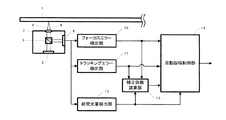
図6の光照射部3は、光ビーム2を光ディスク1に向け所定のパワーで照射する。照射された光ビーム2は、ビームスプリッタ5を通過し、収束レンズ4によって光ディスク1の情報面上に収束される。光ディスク1によって反射した光ビーム2は、ビームスプリッタ5により受光部6に照射される。受光部6は、受光した光量を信号として出力する。光ヘッド9は、光照射部3と収束レンズ4とビームスプリッタ5と受光部6と球面収差補正素子8から構成される。トラッキングエラー検出部11は、受光部6の信号に基づきトラッキングエラー信号(以下TE信号と称す)を検出する。総受光量検出部12は、受光部6の信号に基づき総受光量を検出する。トラッキングエラー検出部11及び総受光量検出部12の信号は、ATT26,27をそれぞれ介して自動振幅制御部14に出力される。自動振幅制御部14は、総受光量が変化すると、その変化量からTE信号の振幅を自動で制御する。つまり、自動振幅制御部14は、トラッキングエラー検出部11の信号に基づき、情報面における光ビームが半径方向に正しく操作されるように制御する。よってディスクの反射率が変化したり、光ビームのパワーがばらついてもTE信号振幅は所定の振幅に保たれる。自動振幅制御部14の信号はコントローラ17に入力される。コントローラ17は、トラッキングアクチュエータ23、ATT26及び球面収差制御部21を制御可能である。
(Embodiment 2)
A second embodiment will be described with reference to FIGS. FIG. 6 is a block diagram showing the configuration of the present embodiment, and FIG. 21 shows the waveforms of the TE signal amplitude and the total received light amount when spherical aberration occurs and when the spherical aberration amount is approximately zero. It is a waveform diagram.
6 emits the
EEPROM18(Electrically Erasable Programmable ROM)は、コントローラ17より読み出し可能である。EEPROM18には、例えば装置の調整検査時に予め光透過層厚が明らかな所定の光ディスクを用いて、その光透過層厚で発生しうる球面収差が略0となるような駆動値を求め、その値をあらかじめ格納している(例えば所定の光ディスクの光透過層厚は100μmあるいは75μmが好ましい。)
球面収差は、波長の逆数とNAの4乗で比例して大きくなるため、微小な光透過層厚のムラに対しても大きな球面収差が発生する。
An EEPROM 18 (Electrically Erasable Programmable ROM) can be read from the
Since the spherical aberration increases in proportion to the reciprocal of the wavelength and the fourth power of NA, a large spherical aberration is generated even with respect to a small unevenness of the light transmission layer thickness.
よって、図6に示すように球面収差補正素子8を駆動し、ディスクの光透過層厚に合致するような球面収差に調整する必要がある。そのために、装置の起動時あるいは所定のコマンドがホスト(不図示)より与えられた時に、コントローラ17は、EEPROM18から球面収差補正素子8の駆動値を取得し、球面収差制御部21を介し球面収差補正素子8を所定の位置に駆動する(図7のステップS1)。なお、球面収差量すなわち駆動値は、ディスクの光透過層厚100μmになっている。よって球面収差制御部21の出力に応じて光照射部3から照射される光ビーム2の球面収差量が補正される。
Therefore, it is necessary to drive the spherical
次に、コントローラ17は、トラッキングエラー検出部11の信号がディスク1の反射率によらず一定の振幅になるように、ATT26を設定する(図7のステップS2)。
第2の実施形態において、EEPROMを用いない変形例を以下に説明する。
(実施形態2の第1変形例)
図9に示すコントローラ17は、球面収差調整部30を内部に有している。球面収差調整部30には、ATT25からの信号が入力される。また、球面収差調整部30は、球面収差制御部21を調整可能である。フォーカス制御をオンした状態で、コントローラ17が、トラッキングアクチュエータ23を駆動することで対物レンズを半径方向に移動させる。すると、TEの振幅(S字)そのものがATT26から球面収差調整部30に送られてくる。コントローラ17は、TEの振幅が略最大となるように、あるいはそのTEの0クロス付近の傾きが略最大となるように、球面収差制御部21を介して球面収差補正素子8を駆動する(図10のステップS4)。その後、コントローラ17は、トラッキングエラー検出部11の信号がディスク1の反射率によらず一定の振幅になるように、ATT26を設定する(図10のステップS2)。
Next, the
A modification in which the EEPROM is not used in the second embodiment will be described below.
(First Modification of Embodiment 2)
The
この結果、TEの振幅調整に球面収差の影響を除去することができる。
(実施形態2の第2変形例)
図6の実施例においてフォーカスエラー検出部(図1を参照)からの信号を用いてステップS4の球面収差粗調整動作を行っても良い。コントローラ17は、フォーカスアクチュエータを駆動させることで対物レンズをアップダウンさせ、その時のフォーカスエラー信号を計測し、その振幅が略最大となるように、あるいはそのFEの0クロス付近の傾きが略最大となるように、球面収差制御部21を介して球面収差補正素子8を駆動する。その後、コントローラ17は、トラッキングエラー検出部11の信号がディスク1の反射率によらず一定の振幅になるように、ATT26を設定する。
As a result, it is possible to remove the influence of spherical aberration on the amplitude adjustment of TE.
(Second Modification of Embodiment 2)
In the embodiment of FIG. 6, the spherical aberration rough adjustment operation in step S4 may be performed using a signal from the focus error detection unit (see FIG. 1). The
(実施形態2の第3変形例)
図8に示す装置では、コントローラ17は、RF検出部24,ATT28からの信号が入力されるジッタ検出部29を有している。RF検出部24は、データを再生するための原信号となるRF信号を生成する。ジッタ検出部29は、RF検出部24からのディスク1に記録されている信号(RF信号)が入力され、その2値化信号より、そのジッタや、さらには、エラーレートに相当する信号品質を表す信号を検出する。コントローラ17は、ジッタや信号品質を表す信号が最適(通常最小)になるように球面収差制御部21を介して球面収差補正素子8を駆動する(図10のステップS4)。その後、コントローラ17は、トラッキングエラー検出部11の信号がディスク1の反射率によらず一定の振幅になるように、ATT25を設定する(図10のステップS2)。この場合も、TEの振幅調整に球面収差の影響を除去することができる。
(Third Modification of Embodiment 2)
In the apparatus shown in FIG. 8, the
(実施形態3)
また実施の形態1、2は、球面収差の補正を行った後、フォーカスエラー信号やトラッキングエラー信号の検出部のゲインATT25やATT26を直接切り換えて、振幅が一定になるような構成を示したが、実施の形態1と2とを組み合わせると、さらに安定した装置を実現することができる。
(Embodiment 3)
In the first and second embodiments, the spherical aberration is corrected, and then the gain ATT25 and ATT26 of the detection unit for the focus error signal and the tracking error signal are directly switched to make the amplitude constant. When the first and second embodiments are combined, a more stable device can be realized.
図11、図12は、実施の形態3を実現する装置の構成である。図11に示す装置は、フォーカスエラー検出部10、ATT25、自動振幅制御部14から構成されるフォーカス制御系と、トラッキングエラー検出部11、ATT26、自動振幅制御部14から構成されるトラッキング制御系とを有している。さらに、これら制御系は、振幅目標補正部32を有している。振幅目標補正部32は、AGC機能を有しており、総受光量検出部12からの信号に基づき、ATT25,26,27の値を調整することができる。コントローラ17は、球面収差調整部30とジッタ検出部29とを有している。
11 and 12 show the configuration of an apparatus that implements the third embodiment. The apparatus shown in FIG. 11 includes a focus control system including a focus
図11の装置における球面収差補正動作について説明する。例えば、装置の組み立て時に、その光ヘッドに最適な所定の球面収差の初期駆動値を求め、EEPROM18に格納しておく。装置の起動時には、コントローラ17は、球面収差の初期駆動値を読み込んで、球面収差制御部21を駆動して、球面収差をその光ヘッドに合致した初期値にする。
次に、コントローラ17は、フォーカスをアップダウンしたときに球面収差調整部30に取り込まれるフォーカスエラー信号の振幅あるいは0クロス付近の傾きが最大になるように、球面収差制御部21を駆動して球面収差補正素子8をさらに適切なところへ移動させる。この状態でFE、ASの振幅は所定の範囲に入ってくるので、フォーカスエラー信号の振幅を調整すれば容易にフォーカス制御を引き込むことが可能となる。
A spherical aberration correction operation in the apparatus of FIG. 11 will be described. For example, when the apparatus is assembled, an initial drive value of a predetermined spherical aberration that is optimal for the optical head is obtained and stored in the
Next, the
次にフォーカスを引き込んだ後に、コントローラ17は、トラッキングエラー検出部11より、ATT26、自動振幅制御部14を介して、球面収差調整部30に取り込まれるトラッキングエラー信号の振幅が略最大になるような球面収差を求め、球面収差制御部21を介して、球面収差補正素子8をさらに適切なところへ移動させる。この状態でTE、ASの振幅は所定の範囲に入ってくるので、トラッキングエラー信号の振幅を調整すれば容易にトラッキング制御を引き込むことが可能となる。
Next, after the focus is drawn, the
さらに、コントローラ17は、トラッキングを引き込んだ後、RF検出部24よりATT27を介して取り込まれるRFの振幅が最大になるように、あるいはそのRFを2値化した信号のジッタをジッタ検出部29で検出してジッタが最小になるように、球面収差制御部21により、球面収差補正素子8を駆動する。
この状態で、コントローラ17が振幅目標補正部32の自動振幅調整の目標を変更すれば、精度の良いゲイン設定を行うことができる。この場合は、ループゲインの変動も少ない。
Further, the
In this state, if the
また、実施形態1および2に示した振幅調整は、ディスク毎の反射率ばらつきにより発生する信号振幅ばらつきを吸収できるが、図11記載の振幅目標補正部32のAGC機能により、起動時あるいは起動後に起きる反射光量変動から発生する信号振幅ばらつきも吸収することができる。
例えば、起動前、すなわちディスク装填時のばらつきは、そのディスクの膜特性や溝パラメータによって生じる。また、起動後のばらつきは、例えば、相変化材料を用いたディスクにおいては、記録した部分と未記録部分とで生じる。このため、トラックの周方向、径方向で反射率の変動が生じる。
Further, the amplitude adjustment shown in the first and second embodiments can absorb the signal amplitude variation caused by the variation in the reflectivity for each disk. However, the AGC function of the amplitude
For example, the variation before starting, that is, when the disc is loaded is caused by the film characteristics and groove parameters of the disc. In addition, for example, in a disc using a phase change material, the variation after starting occurs between a recorded portion and an unrecorded portion. For this reason, the reflectance varies in the circumferential direction and the radial direction of the track.
よってこのようなばらつきを積極的に吸収するために、振幅目標補正部32の自動振幅調整目標を変更してもよい。
さらに、これに変えて、フォーカスあるいはトラッキングのATT25,26を再調整してもよい。
図12に示す装置は、コントローラ17内にループゲイン調整部33を有している。ループゲイン調整部33は、フォーカス制御系およびトラッキング制御系のループゲインを計測調整する。ループゲイン調整部33には、自動振幅制御部14からの信号が入力される。ループゲイン調整部33は、フォーカスアクチュエータ22及びトラッキングアクチュエータ23を駆動可能である。アクチュエータ22,23は、コイル及び永久磁石から構成されている。球面収差の補正後に、ループゲイン調整部33がフォーカス及びトラッキングのゲイン調整を行うと、ループゲインの変動を少なくし、フォーカス、トラッキングを安定にすることができる。
Therefore, the automatic amplitude adjustment target of the amplitude
Further, instead of this, the focus or tracking
The apparatus shown in FIG. 12 has a loop
図11の装置での起動手順における球面収差補正と自動振幅調整のシーケンスについて図17を用いて説明する。
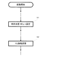
まず、ディスクを回転させた後(不図示)、最初に装置の製造工程等で予め計測した値で、球面収差の補正を行った後(S1)、実施の形態1で説明したようなFE信号の自動振幅調整を行う(S2)。そうすることにより容易にフォーカス制御を引き込むことが可能となる(S5)。
The sequence of spherical aberration correction and automatic amplitude adjustment in the startup procedure in the apparatus of FIG. 11 will be described with reference to FIG.
First, after rotating the disk (not shown), first correcting spherical aberration with a value measured in advance in the manufacturing process of the apparatus (S1), and then the FE signal as described in the first embodiment. The automatic amplitude adjustment is performed (S2). By doing so, it becomes possible to easily pull in the focus control (S5).
フォーカス制御を動作させた後、例えば、トラッキングエラー信号の出力信号が最大になるように球面収差を固定した後(S4)、実施の形態2で説明したようなTE信号の自動振幅調整を行う(S3)。そうすることにより容易にトラッキング制御を引き込むことが可能となる。(S6)
さらにその後、RFの信号振幅が最大になるように、あるいはそのRFを2値化した信号のジッタが最小になるように球面収差を固定した後(S9)、フォーカス制御のループゲイン調整(S7)と、トラッキング制御のループゲイン調整(S8)とを行う。
After operating the focus control, for example, after spherical aberration is fixed so that the output signal of the tracking error signal is maximized (S4), automatic amplitude adjustment of the TE signal as described in the second embodiment is performed (S4). S3). By doing so, tracking control can be easily pulled in. (S6)
Further, after the spherical aberration is fixed so that the RF signal amplitude is maximized or the jitter of the binarized signal is minimized (S9), the focus control loop gain is adjusted (S7). And loop gain adjustment (S8) of tracking control.
このような構成をとることで、ディスクの反射率の変動やレーザパワーのばらつきがあっても、常に所望のループゲインにすることができ、安定なフォーカス制御系、トラッキング制御系を具備した装置を構成できる
以上に述べた処理の効果について説明する。
1)ディスクを回転させ(不図示)、最初に装置の製造工程等で予め計測した値で、球面収差あるいはコマ収差の補正を行い(S1)、次に実施の形態1で説明したようなFE信号の自動振幅調整を行い(S2)。さらにその後、フォーカス制御のループゲイン調整をする(S7)。そのため、ディスクの反射率の変動やレーザパワーのばらつきがあっても常に所望のループゲインにすることができ、安定なフォーカス制御系を構成できる。
By adopting such a configuration, it is possible to always achieve a desired loop gain even if there are fluctuations in the reflectivity of the disk and variations in the laser power, and a device equipped with a stable focus control system and tracking control system. The effects of the processing described above can be described.
1) The disk is rotated (not shown), and first, spherical aberration or coma aberration is corrected with a value measured in advance in the manufacturing process of the apparatus (S1), and then FE as described in the first embodiment. Automatic signal amplitude adjustment is performed (S2). Thereafter, the loop gain of the focus control is adjusted (S7). Therefore, a desired loop gain can always be obtained even if there are fluctuations in the reflectivity of the disk and variations in the laser power, and a stable focus control system can be configured.
2)ディスクを回転させ、最初に装置の製造工程等で予め計測した値で、球面収差の補正を行い(S1)、実施の形態2で説明したようなTE信号の自動振幅調整を行い(S3)、さらにその後、トラッキング制御のループゲイン調整をする(S8)。そのため、ディスクの反射率の変動やレーザパワーのばらつきがあっても常に所望のループゲインにすることができ、安定なトラッキング制御系を構成できる。 2) The disk is rotated, and the spherical aberration is corrected with the value measured in advance in the manufacturing process of the apparatus (S1), and the automatic amplitude adjustment of the TE signal as described in the second embodiment is performed (S3). Thereafter, the loop gain of the tracking control is adjusted (S8). Therefore, even if there are fluctuations in the reflectivity of the disk and variations in the laser power, a desired loop gain can always be obtained, and a stable tracking control system can be configured.
以上のように装置の起動シーケンスの所定タイミングで適宜最適に球面収差の制御を行い、その後にFE、TEの振幅調整、あるいはループゲインの調整を行うように構成することで、ディスクの光透過層厚が変動しても、安定なフォーカス、トラッキングを実現することができる。
(実施形態4)
本実施の形態は、球面収差を光学的に直接検出し、その信号に基づいて球面収差補正素子を駆動した後でフォーカスエラー信号の振幅調整を行うものである。図15はその構成を示すブロック図であり、実施の形態2及び3と同様の部分は同じ番号を付し、その説明を省略する。
As described above, the configuration is such that the spherical aberration is appropriately and optimally controlled at a predetermined timing in the startup sequence of the apparatus, and then the amplitude adjustment of FE and TE, or the adjustment of loop gain is performed. Even if the thickness varies, stable focus and tracking can be realized.
(Embodiment 4)
In this embodiment, spherical aberration is optically detected directly, and the amplitude of the focus error signal is adjusted after driving the spherical aberration correction element based on the signal. FIG. 15 is a block diagram showing the configuration, and the same parts as those in the second and third embodiments are denoted by the same reference numerals, and the description thereof is omitted.
また図14は光学的に直接検出した球面収差信号の特性の一例を示す。球面収差信号は、フォーカスエラー信号あるいはトラッキングエラー信号の信号振幅が最大となる時に略0となるような特性を持つ。
球面収差を直接的に検出する方法として、球面収差検出部31を設ける。球面収差検出部31は、図13に示すように、外側部FE生成器と、内側部FE生成器と、減算器とを有しており、光ビームの内側部と外側部の光量差を検出できるようになっている。球面収差検出部31の出力である球面収差信号は、コントローラ17に出力される。この球面収差信号により、コントローラ17は光ディスク1上の球面収差を直接検出することができる。コントローラ17は、球面収差の値が略0となるように球面収差制御部21を介し、球面収差補正素子8を駆動する。この帰還ループが動作した後、フォーカスエラー信号の振幅調整、トラッキングエラー信号の振幅調整、あるいはフォーカス制御におけるAGCの目標ゲインの調整、トラッキングエラー制御におけるAGCの目標ゲインの調整、あるいはフォーカス制御におけるループゲインの調整、トラッキングエラー制御にループゲインの調整を行えば、同様の効果を得ることができる。
FIG. 14 shows an example of the characteristic of the spherical aberration signal detected directly optically. The spherical aberration signal has such a characteristic that it becomes substantially zero when the signal amplitude of the focus error signal or tracking error signal becomes maximum.
A
(実施形態5)
本実施の形態は、球面収差を光学的に直接検出し、その信号に基づいて球面収差補正素子を駆動した後でトラッキングエラー信号の振幅調整を行うものである。図16はその構成を示すブロック図である。
なお、実施の形態1〜5において球面収差検出の方法及び、収差補正素子の構成には何ら限定を行うものではない。
(Embodiment 5)
In this embodiment, the spherical aberration is optically detected directly, and the amplitude of the tracking error signal is adjusted after driving the spherical aberration correction element based on the signal. FIG. 16 is a block diagram showing the configuration.
In the first to fifth embodiments, the spherical aberration detection method and the configuration of the aberration correction element are not limited at all.
(実施形態6)
また光ディスクの反りや垂れなどによりディスクのチルトが発生すると、あるいは光学的な部品精度がばらつきを持つと、光ディスク上のビームには、球面収差ではなくコマ収差が発生する。特に図24に示すように、ディスクにチルトが発生すると、光ビームの入射光の光路長が変わり、光ビームスポット上にコマ収差が発生する。コマ収差は、その発生方向や高次の回折光の影響を考えると、球面収差同様、図18に示すようにTE振幅やFE振幅に影響を与え、サーボ系のループゲインの変動の原因となる。
(Embodiment 6)
Further, when the disc tilts due to warpage or sagging of the optical disc, or when the optical component accuracy varies, coma aberration occurs instead of spherical aberration in the beam on the optical disc. In particular, as shown in FIG. 24, when the disc tilts, the optical path length of the incident light of the light beam changes, and coma aberration occurs on the light beam spot. In consideration of the direction of generation and the influence of higher-order diffracted light, coma aberration affects TE amplitude and FE amplitude as shown in FIG. 18 as well as spherical aberration, and causes fluctuations in the loop gain of the servo system. .
よってこのような場合にも、実施の形態1〜5を同様に適用する。すなわちコマ収差を補正した後、球面収差補正素子を駆動する。この帰還ループが動作した後、フォーカスエラー信号の振幅調整、トラッキングエラー信号の振幅調整、あるいはフォーカス制御におけるAGCの目標ゲインの調整、トラッキングエラー制御におけるAGCの目標ゲインの調整、あるいはフォーカス制御におけるループゲインの調整、トラッキングエラー制御におけるループゲインの調整を行えば、同様の効果を得ることができる。 Therefore, also in such a case, Embodiments 1-5 are applied similarly. That is, after correcting the coma aberration, the spherical aberration correction element is driven. After this feedback loop operates, the focus error signal amplitude adjustment, tracking error signal amplitude adjustment, AGC target gain adjustment in focus control, AGC target gain adjustment in tracking error control, or loop gain in focus control The same effect can be obtained by adjusting the loop gain in the tracking error control.
特にコマ収差は、ディスクのチルトが支配的であるため、図19に示すようのレンズのチルトを、例えば、レンズの高さ、すなわちフォーカスの駆動値から求め、レンズを、ディスクの傾きに合致するように駆動する。以上により、上記した制御を容易に実現することができる。
(実施形態7)
図22は、DVDで既に標準規格されていたり、次世代の光ディスクでBlu−rayディスクで提案されているような2層ディスクにおいて、層間移動をした場合のレンズとディスクの模式図を示している。図22(a)は、レンズ位置を示す信号を示す波形図、図22(b)は、フォーカス駆動信号を示す波形図、図22(c)は、球面収差の駆動信号を示す波形図、図22(d)は、自動振幅制御のON/OFFを示す波形図である。
In particular, since coma aberration is dominated by the tilt of the disk, the tilt of the lens as shown in FIG. 19 is obtained from, for example, the lens height, that is, the focus drive value, and the lens matches the tilt of the disk. To drive. As described above, the above-described control can be easily realized.
(Embodiment 7)
FIG. 22 shows a schematic diagram of a lens and a disk in a case where a layer movement is performed in a dual-layer disk that is already standardized on DVD or proposed as a next-generation optical disk as a Blu-ray disk. . 22A is a waveform diagram showing a signal indicating a lens position, FIG. 22B is a waveform diagram showing a focus drive signal, and FIG. 22C is a waveform diagram showing a drive signal for spherical aberration. 22 (d) is a waveform diagram showing ON / OFF of automatic amplitude control.
2層ディスクにおいては、最初L0層を記録あるいは再生している状態では、L0層の厚みに対応した球面収差が調整されている。次にL1層へ移動する場合は、一旦トラッキング制御をオフし、フォーカス制御をホールドした後、フォーカス制御系に図22(b)に示すような駆動パルスを印加し、収束レンズをL0からL1に移動させる。
このとき球面収差制御部は、図22(c)に示すように、L1層に対応した球面収差に追従するよう動作する。
In a dual-layer disc, spherical aberration corresponding to the thickness of the L0 layer is adjusted when the L0 layer is initially recorded or reproduced. Next, when moving to the L1 layer, once tracking control is turned off and focus control is held, a drive pulse as shown in FIG. 22B is applied to the focus control system, and the convergent lens is changed from L0 to L1. Move.
At this time, the spherical aberration controller operates to follow the spherical aberration corresponding to the L1 layer, as shown in FIG.
このときに、球面収差の駆動素子としては、通常ステッピングモータや液晶素子が用いられる場合が多く、先に述べたボイスコイルで構成された対物レンズアクチュータで光ビームスポットがL1に移動完了していても、球面収差は最適な状態になっていない。したがってこの状態でトラッキング制御をオンし、自動振幅制御をオンさせると、球面収差がずれている状態で補正され、その後球面収差が追従してくるに連れ、フォーカス制御のループゲインが上昇してしまう。 At this time, a stepping motor or a liquid crystal element is usually used as a driving element for spherical aberration, and the light beam spot has been moved to L1 by the objective lens actuator composed of the voice coil described above. However, the spherical aberration is not optimal. Therefore, when tracking control is turned on in this state and automatic amplitude control is turned on, the spherical aberration is corrected in a shifted state, and the focus control loop gain increases as the spherical aberration follows thereafter. .
よって図22(d)に示すように光ビームがL0からL1に移動し、さらに球面収差が十分追従した後、自動振幅制御を動作させれば、層間のジャンプが非常に安定になる。また本実施の形態7では2層ディスクを例にあげて説明したが、2層以上の3層、4層といった多層ディスクでも十分適用することができる。 Therefore, as shown in FIG. 22 (d), if the automatic amplitude control is operated after the light beam moves from L0 to L1 and the spherical aberration sufficiently follows, the jump between layers becomes very stable. In the seventh embodiment, a two-layer disc has been described as an example. However, a multi-layer disc having two or more layers of three layers and four layers can be sufficiently applied.
本発明は、球面収差の補正を行って、FE、TEの振幅を確定させた後、所定の振幅するためのAGCを動作させるので、2層以上のディスク、特に青色レーザやNAの大きなレンズを用いた次世代の高密度のディスクドライブで有用であり、特に記録系のディスクで記録、未記録で反射率が変動したり、2層のメディアで層間ジャンプを安定させる場合に、フォーカス制御、トラッキング制御を安定にすることができ、その効果は大きい。 In the present invention, after correcting the spherical aberration and determining the amplitudes of FE and TE, the AGC for operating the predetermined amplitude is operated. Therefore, a disc having two or more layers, particularly a blue laser or a lens having a large NA is used. This is useful for the next-generation high-density disk drive used, especially when recording and recording with a recording disk and the reflectivity fluctuates when recording is not performed, and when the interlayer jump is stabilized with two-layer media, focus control and tracking The control can be stabilized and the effect is great.
1 光ディスク
2 光ビーム
3 光照射部
4 収束レンズ
5 ビームスプリッタ
6 受光部
7 光ヘッド
8 球面収差補正素子
9 光ヘッド
10 フォーカスエラー検出部
11 トラッキングエラー検出部
12 総受光量検出部
13 補正係数演算部
14 自動振幅制御部
17 コントローラ
18 EEPROM
21 球面収差制御部
22 レンズアクチュエータ
23 レンズアクチュエータ
24 RF検出部
25 FEATT
26 TEATT
27 ASATT
28 RFATT
29 ジッタ検出部
30 球面収差調整部
31 球面収差検出部
32 振幅目標補正部
33 ループゲイン調整部
DESCRIPTION OF
21
26 TEATT
27 ASATT
28 RFATT
29
Claims (26)
前記光透過層で発生しうる球面収差が略0となる駆動値情報を記憶する記憶部と、
球面収差補正素子を有し、前記駆動値情報に基づいて前記球面収差補正素子を駆動することで、前記光ビームに発生している球面収差を予め補正する球面収差補正手段と、
前記情報担体の光ビームの収束状態に応じたフォーカスエラー信号を検出するフォーカス検出手段と、
前記フォーカスエラー信号のゲイン調整を行い、ゲイン調整を行った前記フォーカスエラー信号を調整後フォーカスエラー信号として出力するフォーカスエラー信号ゲイン調整部と、
光ディスクからの全光量に対応した信号であるAS信号を検出する全光量検出手段と、
前記AS信号と前記調整後フォーカスエラー信号とに基づいて、前記調整後フォーカスエラー信号に対して、自動振幅制御を行い、自動振幅制御を行った信号をAGCフォーカスエラー信号として出力する自動振幅制御部と、
前記収束レンズを駆動する収束レンズ駆動部と、
前記フォーカスエラー信号ゲイン調整部におけるゲイン調整を行うためのゲイン値を設定するとともに、前記収束レンズ駆動部を駆動制御することでフォーカス制御を行う制御部と、
を備え、
前記制御部は、前記球面収差補正手段が前記光ビームに発生している球面収差を補正した後、前記調整後フォーカスエラー信号の振幅値が、光ディスクの反射率によらず一定の値となるように前記フォーカスエラー信号ゲイン調整部のゲイン調整を行うとともに、前記フォーカスエラー信号の振幅を調整することで、フォーカス制御を引き込む、
光ディスク装置。 An optical disc apparatus that performs recording and reproduction by irradiating a light beam onto an information surface of an information carrier coated with a light transmission layer by a converging lens ,
A storage unit that stores drive value information in which spherical aberration that may occur in the light transmission layer is substantially zero;
A spherical aberration correction unit that has a spherical aberration correction element and that corrects the spherical aberration generated in the light beam in advance by driving the spherical aberration correction element based on the drive value information ;
A focus detection means for detecting a focus error signal according to a convergence state of the light beam of the information carrier;
A focus error signal gain adjustment unit that performs gain adjustment of the focus error signal and outputs the focus error signal after gain adjustment as a focus error signal after adjustment;
A total light quantity detecting means for detecting an AS signal which is a signal corresponding to the total light quantity from the optical disc;
An automatic amplitude control unit that performs automatic amplitude control on the adjusted focus error signal based on the AS signal and the adjusted focus error signal, and outputs the signal subjected to the automatic amplitude control as an AGC focus error signal When,
A converging lens driving unit for driving the converging lens;
A control unit that sets a gain value for performing gain adjustment in the focus error signal gain adjusting unit, and performs focus control by driving and controlling the convergent lens driving unit;
With
After the spherical aberration correcting means corrects the spherical aberration generated in the light beam by the spherical aberration correcting means, the control unit is configured so that the amplitude value of the adjusted focus error signal becomes a constant value regardless of the reflectance of the optical disc. In addition to adjusting the gain of the focus error signal gain adjustment unit, the focus control is pulled in by adjusting the amplitude of the focus error signal.
Optical disk device.
前記情報担体の光ビームの収束状態に応じたフォーカスエラー信号を検出するフォーカス検出手段と、
前記フォーカスエラー信号のゲイン調整を行い、ゲイン調整を行った前記フォーカスエラー信号を調整後フォーカスエラー信号として出力するフォーカスエラー信号ゲイン調整部と、
光ディスクからの全光量に対応した信号であるAS信号を検出する全光量検出手段と、
前記AS信号と前記調整後フォーカスエラー信号とに基づいて、前記調整後フォーカスエラー信号に対して、自動振幅制御を行い、自動振幅制御を行った信号をAGCフォーカスエラー信号として出力する自動振幅制御部と、
前記調整後フォーカスエラー信号の振幅が略最大となるように、前記光ビームに発生している球面収差を補正する球面収差補正手段と、
前記収束レンズを駆動する収束レンズ駆動部と、
前記フォーカスエラー信号ゲイン調整部におけるゲイン調整を行うためのゲイン値を設定するとともに、前記収束レンズ駆動部を駆動制御することでフォーカス制御を行う制御部と、
を備え、
前記制御部は、前記球面収差補正手段が前記調整後フォーカスエラー信号の振幅が略最大となるように、前記光ビームに発生している球面収差を補正した後、前記調整後フォーカスエラー信号の振幅値が、光ディスクの反射率によらず一定の値となるように前記フォーカスエラー信号ゲイン調整部のゲイン調整を行うとともに、前記フォーカスエラー信号の振幅を調整することで、フォーカス制御を引き込む、
光ディスク装置。 An optical disc apparatus that performs recording and reproduction by irradiating a light beam onto an information surface of an information carrier coated with a light transmission layer by a converging lens ,
A focus detection means for detecting a focus error signal according to a convergence state of the light beam of the information carrier;
A focus error signal gain adjustment unit that performs gain adjustment of the focus error signal and outputs the focus error signal after gain adjustment as a focus error signal after adjustment;
A total light quantity detecting means for detecting an AS signal which is a signal corresponding to the total light quantity from the optical disc;
An automatic amplitude control unit that performs automatic amplitude control on the adjusted focus error signal based on the AS signal and the adjusted focus error signal, and outputs the signal subjected to the automatic amplitude control as an AGC focus error signal When,
Spherical aberration correcting means for correcting spherical aberration generated in the light beam so that the amplitude of the adjusted focus error signal is substantially maximized;
A converging lens driving unit for driving the converging lens;
A control unit that sets a gain value for performing gain adjustment in the focus error signal gain adjusting unit, and performs focus control by driving and controlling the convergent lens driving unit;
With
The control unit corrects the spherical aberration generated in the light beam so that the spherical aberration correcting unit substantially maximizes the amplitude of the adjusted focus error signal, and then adjusts the amplitude of the adjusted focus error signal. While performing the gain adjustment of the focus error signal gain adjustment unit so that the value becomes a constant value regardless of the reflectance of the optical disc, the focus control is drawn by adjusting the amplitude of the focus error signal.
Optical disk device.
前記情報担体の光ビームの収束状態に応じたフォーカスエラー信号を検出するフォーカス検出手段と、 A focus detection means for detecting a focus error signal according to a convergence state of the light beam of the information carrier;
前記フォーカスエラー信号のゲイン調整を行い、ゲイン調整を行った前記フォーカスエラー信号を調整後フォーカスエラー信号として出力するフォーカスエラー信号ゲイン調整部と、 A focus error signal gain adjustment unit that performs gain adjustment of the focus error signal and outputs the focus error signal after gain adjustment as a focus error signal after adjustment;
光ディスクからの全光量に対応した信号であるAS信号を検出する全光量検出手段と、 A total light quantity detecting means for detecting an AS signal which is a signal corresponding to the total light quantity from the optical disc;
前記AS信号と前記調整後フォーカスエラー信号とに基づいて、前記調整後フォーカスエラー信号に対して、自動振幅制御を行い、自動振幅制御を行った信号をAGCフォーカスエラー信号として出力する自動振幅制御部と、 An automatic amplitude control unit that performs automatic amplitude control on the adjusted focus error signal based on the AS signal and the adjusted focus error signal, and outputs the signal subjected to the automatic amplitude control as an AGC focus error signal When,
前記調整後フォーカスエラー信号の0クロス付近の傾きが略最大となるように、前記光ビームに発生している球面収差を補正する球面収差補正手段と、 Spherical aberration correction means for correcting spherical aberration generated in the light beam so that the inclination of the adjusted focus error signal near the zero cross becomes substantially maximum;
前記収束レンズを駆動する収束レンズ駆動部と、 A converging lens driving unit for driving the converging lens;
前記フォーカスエラー信号ゲイン調整部におけるゲイン調整を行うためのゲイン値を設定するとともに、前記収束レンズ駆動部を駆動制御することでフォーカス制御を行う制御部と、 A control unit that sets a gain value for performing gain adjustment in the focus error signal gain adjusting unit, and performs focus control by driving and controlling the convergent lens driving unit;
を備え、With
前記制御部は、前記球面収差補正手段が前記調整後フォーカスエラー信号の0クロス付近の傾きが略最大となるように、前記光ビームに発生している球面収差を補正した後、前記調整後フォーカスエラー信号の振幅値が、光ディスクの反射率によらず一定の値となるように前記フォーカスエラー信号ゲイン調整部のゲイン調整を行うとともに、前記フォーカスエラー信号の振幅を調整することで、フォーカス制御を引き込む、 The control unit corrects the spherical aberration occurring in the light beam so that the spherical aberration correction means has a maximum inclination near the zero cross of the adjusted focus error signal, and then the adjusted focus. Focus adjustment is performed by adjusting the gain of the focus error signal gain adjusting unit so that the amplitude value of the error signal becomes a constant value regardless of the reflectivity of the optical disc, and adjusting the amplitude of the focus error signal. Pull in,
光ディスク装置。 Optical disk device.
前記制御部は、前記光ディスク装置のフォーカス制御系のループゲインを計測調整するフォーカスゲイン調整手段を有し、
前記フォーカスゲイン調整手段は、前記光ディスク装置の起動時における前記球面収差補正手段での補正が終了した後、前記ループゲインを計測調整する、
請求項1から3のいずれかに記載の光ディスク装置。 The spherical aberration correction means corrects the spherical aberration generated in the light beam when the optical disc device is started up,
The control unit includes a focus gain adjustment unit that measures and adjusts a loop gain of a focus control system of the optical disc apparatus ,
The focus gain adjustment means, after the correction by the spherical aberration correcting means definitive at the start of the optical disk device is completed, the measurement adjust the loop gain,
The optical disc apparatus according to claim 1 .
前記球面収差補正手段は、前記光ディスク装置の起動時に前記再生信号振幅検出手段の信号が略最大となるように、球面収差を補正することを特徴とする、
請求項1から3のいずれかに記載の光ディスク装置。 Reproduction signal amplitude detection means for detecting the amplitude of the reproduction signal of the information already recorded on the information carrier,
The spherical aberration correction means isOptical discSpherical aberration is corrected so that the signal of the reproduction signal amplitude detection means becomes substantially maximum when the apparatus is started,
Claim1 to 3An optical disc device according to any one of the above.
前記球面収差補正手段は、前記光ディスク装置の起動時に前記再生信号ジッタ検出手段の信号が最適になるように、球面収差を補正することを特徴とする、
請求項1から3のいずれかに記載の光ディスク装置。 Reproduction signal jitter detection means for detecting jitter of a reproduction signal of information already recorded on the information carrier,
The spherical aberration correction unit corrects the spherical aberration so that the signal of the reproduction signal jitter detection unit is optimized when the optical disc apparatus is started.
The optical disc apparatus according to claim 1 .
前記球面収差補正手段は、前記光ディスク装置の起動時に前記エラー検出手段の信号に基づいて、球面収差を補正することを特徴とする、
請求項1から3のいずれかに記載の光ディスク装置。 Binarization means for binarizing a reproduction signal of information already recorded on the information carrier; and error detection means for detecting a bit error of the binarized reproduction signal or a signal corresponding thereto,
The spherical aberration correction means, based on the signal of said error detecting means when starting the optical disk apparatus, and correcting the spherical aberration,
The optical disc apparatus according to claim 1 .
前記球面収差補正手段は、前記トラッキング検出手段により検出された前記トラッキングエラー信号の信号振幅または0クロス付近の傾きが略最大となるように、前記光ディスク装置の起動時に球面収差を補正することを特徴とする、
請求項1から3のいずれかに記載の光ディスク装置。 Tracking detection means for detecting a tracking error signal corresponding to a position error between the light beam and the track of the information carrier;
The spherical aberration correction means, the so signal amplitude or 0 tilt around the cross of the tracking detection the tracking error signal detected by the means is substantially maximum, characterized in that to correct spherical aberration at the start of the optical disk device And
The optical disc apparatus according to claim 1 .
請求項1から3のいずれかに記載の光ディスク装置。 In a multilayer disk having two or more layers of information surfaces stacked, the spherical aberration correction means is configured to correct spherical aberration for each layer,
The optical disc apparatus according to claim 1 .
各層の移動時に前記光ビームに発生する球面収差量が所定の範囲に追従するまで、前記フォーカスエラー信号ゲイン調整部は、前記フォーカスエラー信号の振幅を所定の振幅に調整する動作を開始しないことを特徴とする、 The focus error signal gain adjustment unit does not start the operation of adjusting the amplitude of the focus error signal to a predetermined amplitude until the amount of spherical aberration generated in the light beam when the respective layers move follows a predetermined range. Features
請求項1から3のいずれか1項に記載の光ディスク装置。 The optical disk apparatus according to claim 1.
前記光透過層で発生しうる球面収差が略0となる駆動値情報を記憶する記憶部と、
球面収差補正素子を有し、前記駆動値情報に基づいて前記球面収差補正素子を駆動することで、前記光ビームに発生している球面収差を予め補正する球面収差補正手段と、
前記情報担体の光ビームとトラックとの位置誤差に応じたトラッキングエラー信号を検出するトラッキング検出手段と、
前記トラッキングエラー信号のゲイン調整を行い、ゲイン調整を行った前記トラッキングエラー信号を調整後トラッキングエラー信号として出力するトラッキングエラー信号ゲイン調整部と、
光ディスクからの全光量に対応した信号であるAS信号を検出する全光量検出手段と、
前記AS信号と前記調整後トラッキングエラー信号とに基づいて、前記調整後トラッキングエラー信号に対して、自動振幅制御を行い、自動振幅制御を行った信号をAGCトラッキングエラー信号として出力する自動振幅制御部と、
前記収束レンズを駆動する収束レンズ駆動部と、
前記トラッキングエラー信号ゲイン調整部におけるゲイン調整を行うためのゲイン値を設定するとともに、前記収束レンズ駆動部を駆動制御することでトラッキング制御を行う制御部と、
を備え、
前記制御部は、前記球面収差補正手段が前記光ビームに発生している球面収差を補正した後、前記調整後トラッキングエラー信号の振幅値が、光ディスクの反射率によらず一定の値となるように前記トラッキングエラー信号ゲイン調整部のゲイン調整を行うとともに、前記トラッキングエラー信号の振幅を調整することで、トラッキング制御を引き込む、
光ディスク装置。 An optical disc apparatus that performs recording and reproduction by irradiating a light beam onto an information surface of an information carrier coated with a light transmission layer by a converging lens ,
A storage unit that stores drive value information in which spherical aberration that may occur in the light transmission layer is substantially zero;
A spherical aberration correction unit that has a spherical aberration correction element and that corrects the spherical aberration generated in the light beam in advance by driving the spherical aberration correction element based on the drive value information ;
Tracking detection means for detecting a tracking error signal according to a positional error between the light beam and the track of the information carrier;
A tracking error signal gain adjusting unit that adjusts the gain of the tracking error signal and outputs the adjusted tracking error signal as a tracking error signal after adjustment.
A total light quantity detecting means for detecting an AS signal which is a signal corresponding to the total light quantity from the optical disc;
An automatic amplitude control unit that performs automatic amplitude control on the adjusted tracking error signal based on the AS signal and the adjusted tracking error signal, and outputs the signal subjected to automatic amplitude control as an AGC tracking error signal When,
A converging lens driving unit for driving the converging lens;
A control unit that sets a gain value for performing gain adjustment in the tracking error signal gain adjustment unit and performs tracking control by driving and controlling the convergent lens driving unit;
With
The control unit corrects the spherical aberration generated in the light beam by the spherical aberration correcting unit, so that the amplitude value of the adjusted tracking error signal becomes a constant value regardless of the reflectivity of the optical disc. In addition to performing gain adjustment of the tracking error signal gain adjustment unit, the tracking control signal is drawn by adjusting the amplitude of the tracking error signal.
Optical disk device.
前記情報担体の光ビームとトラックとの位置誤差に応じたトラッキングエラー信号を検出するトラッキング検出手段と、
前記トラッキングエラー信号のゲイン調整を行い、ゲイン調整を行った前記トラッキングエラー信号を調整後トラッキングエラー信号として出力するトラッキングエラー信号ゲイン調整部と、
光ディスクからの全光量に対応した信号であるAS信号を検出する全光量検出手段と、
前記AS信号と前記調整後トラッキングエラー信号とに基づいて、前記調整後トラッキングエラー信号に対して、自動振幅制御を行い、自動振幅制御を行った信号をAGCトラッキングエラー信号として出力する自動振幅制御部と、
前記調整後トラッキングエラー信号の振幅が略最大となるように、前記光ビームに発生している球面収差を補正する球面収差補正手段と、
前記収束レンズを駆動する収束レンズ駆動部と、
前記トラッキングエラー信号ゲイン調整部におけるゲイン調整を行うためのゲイン値を設定するとともに、前記収束レンズ駆動部を駆動制御することでトラッキング制御を行う制御部と、
を備え、
前記制御部は、前記球面収差補正手段が前記調整後トラッキングエラー信号の振幅が略最大となるように、前記光ビームに発生している球面収差を補正した後、前記調整後トラッキングエラー信号の振幅値が、光ディスクの反射率によらず一定の値となるように前記トラッキングエラー信号ゲイン調整部のゲイン調整を行うとともに、前記トラッキングエラー信号の振幅を調整することで、トラッキング制御を引き込む、
光ディスク装置。 An optical disc apparatus that performs recording and reproduction by irradiating a light beam onto an information surface of an information carrier coated with a light transmission layer by a converging lens ,
Tracking detection means for detecting a tracking error signal according to a positional error between the light beam and the track of the information carrier;
A tracking error signal gain adjusting unit that adjusts the gain of the tracking error signal and outputs the adjusted tracking error signal as a tracking error signal after adjustment.
A total light quantity detecting means for detecting an AS signal which is a signal corresponding to the total light quantity from the optical disc;
An automatic amplitude control unit that performs automatic amplitude control on the adjusted tracking error signal based on the AS signal and the adjusted tracking error signal, and outputs the signal subjected to automatic amplitude control as an AGC tracking error signal When,
Spherical aberration correction means for correcting spherical aberration generated in the light beam so that the amplitude of the tracking error signal after adjustment is substantially maximized;
A converging lens driving unit for driving the converging lens;
A control unit that sets a gain value for performing gain adjustment in the tracking error signal gain adjustment unit and performs tracking control by driving and controlling the convergent lens driving unit;
With
The control unit corrects the spherical aberration generated in the light beam so that the amplitude of the tracking error signal after adjustment is substantially maximized by the spherical aberration correction unit, and then the amplitude of the tracking error signal after adjustment. While performing the gain adjustment of the tracking error signal gain adjustment unit so that the value becomes a constant value regardless of the reflectivity of the optical disc, and by adjusting the amplitude of the tracking error signal, pulling in the tracking control,
Optical disk device.
前記情報担体の光ビームとトラックとの位置誤差に応じたトラッキングエラー信号を検出するトラッキング検出手段と、 Tracking detection means for detecting a tracking error signal according to a positional error between the light beam and the track of the information carrier;
前記トラッキングエラー信号のゲイン調整を行い、ゲイン調整を行った前記トラッキングエラー信号を調整後トラッキングエラー信号として出力するトラッキングエラー信号ゲイン調整部と、 A tracking error signal gain adjusting unit that adjusts the gain of the tracking error signal and outputs the adjusted tracking error signal as a tracking error signal after adjustment.
光ディスクからの全光量に対応した信号であるAS信号を検出する全光量検出手段と、 A total light quantity detecting means for detecting an AS signal which is a signal corresponding to the total light quantity from the optical disc;
前記AS信号と前記調整後トラッキングエラー信号とに基づいて、前記調整後トラッキングエラー信号に対して、自動振幅制御を行い、自動振幅制御を行った信号をAGCトラッキングエラー信号として出力する自動振幅制御部と、 An automatic amplitude control unit that performs automatic amplitude control on the adjusted tracking error signal based on the AS signal and the adjusted tracking error signal, and outputs the signal subjected to automatic amplitude control as an AGC tracking error signal When,
前記調整後トラッキングエラー信号の0クロス付近の傾きが略最大となるように、前記光ビームに発生している球面収差を補正する球面収差補正手段と、 Spherical aberration correction means for correcting the spherical aberration generated in the light beam so that the inclination of the tracking error signal after adjustment near the zero cross becomes substantially maximum;
前記収束レンズを駆動する収束レンズ駆動部と、 A converging lens driving unit for driving the converging lens;
前記トラッキングエラー信号ゲイン調整部におけるゲイン調整を行うためのゲイン値を設定するとともに、前記収束レンズ駆動部を駆動制御することでトラッキング制御を行う制御部と、 A control unit that sets a gain value for performing gain adjustment in the tracking error signal gain adjustment unit and performs tracking control by driving and controlling the convergent lens driving unit;
を備え、With
前記制御部は、前記球面収差補正手段が前記調整後トラッキングエラー信号の0クロス付近の傾きが略最大となるように、前記光ビームに発生している球面収差を補正した後、前記調整後トラッキングエラー信号の振幅値が、光ディスクの反射率によらず一定の値となるように前記トラッキングエラー信号ゲイン調整部のゲイン調整を行うとともに、前記トラッキングエラー信号の振幅を調整することで、トラッキング制御を引き込む、 The control unit corrects the spherical aberration occurring in the light beam so that the spherical aberration correcting unit has a maximum inclination near the zero cross of the adjusted tracking error signal, and then the adjusted tracking. The tracking error control is performed by adjusting the gain of the tracking error signal gain adjusting unit so that the error signal amplitude value is constant regardless of the reflectivity of the optical disc, and adjusting the tracking error signal amplitude. Pull in,
光ディスク装置。 Optical disk device.
前記制御部は、前記光ディスク装置のトラッキング制御系のループゲインを計測調整するトラッキングゲイン調整手段を有し、
前記トラッキングゲイン調整手段は、前記光ディスク装置の起動時における前記球面収差補正手段での補正が終了した後、前記ループゲインを計測調整する、
請求項11から13いずれかに記載の光ディスク装置。 The spherical aberration correction means corrects the spherical aberration generated in the light beam when the optical disc device is started up,
The control unit includes tracking gain adjustment means for measuring and adjusting a loop gain of a tracking control system of the optical disc device ,
The tracking gain adjustment means, after the correction by the spherical aberration correcting means definitive at the start of the optical disk device is completed, the measurement adjust the loop gain,
The optical disk device according to claim 11 .
前記球面収差補正手段は、前記光ディスク装置の起動時に前記再生信号振幅検出手段の信号が略最大となるように、球面収差を補正することを特徴とする、
請求項11から13のいずれかに記載の光ディスク装置。 Reproduction signal amplitude detection means for detecting the amplitude of the reproduction signal of the information already recorded on the information carrier,
The spherical aberration correction means corrects the spherical aberration so that the signal of the reproduction signal amplitude detection means becomes substantially maximum when the optical disc apparatus is started.
The optical disc apparatus according to claim 11 .
前記球面収差補正手段は、前記光ディスク装置の起動時に前記再生信号ジッタ検出手段の信号が最適になるように、球面収差を補正することを特徴とする、
請求項11から13のいずれかに記載の光ディスク装置。 Reproduction signal jitter detection means for detecting jitter of a reproduction signal of information already recorded on the information carrier,
The spherical aberration correction unit corrects the spherical aberration so that the signal of the reproduction signal jitter detection unit is optimized when the optical disc apparatus is started.
The optical disc apparatus according to claim 11 .
前記球面収差補正手段は、前記光ディスク装置の起動時に前記エラー検出手段の信号に基づいて、球面収差を補正することを特徴とする、
請求項11から13のいずれかに記載の光ディスク装置。 Binarization means for binarizing a reproduction signal of information already recorded on the information carrier; and error detection means for detecting a bit error of the binarized reproduction signal or a signal corresponding thereto,
The spherical aberration correction means, based on the signal of said error detecting means when starting the optical disk apparatus, and correcting the spherical aberration,
The optical disc apparatus according to claim 11 .
前記球面収差補正手段は、前記フォーカス検出手段により検出された前記フォーカスエラー信号の信号振幅または0クロス付近の傾きが略最大となるように、前記光ディスク装置の起動時に球面収差を補正することを特徴とする、
請求項11から13のいずれかに記載の光ディスク装置。 A focus detection means for detecting a focus error signal corresponding to a position error between the light beam and the track of the information carrier;
The spherical aberration correction means, so that the inclination of the signal amplitude or near zero cross detected the focus error signal by the focus detection means is substantially maximum, characterized in that to correct spherical aberration at the start of the optical disk device And
The optical disc apparatus according to claim 11 .
請求項11から13のいずれかに記載の光ディスク装置。 In a multilayer disk having two or more layers of information surfaces stacked, the spherical aberration correction means is configured to correct spherical aberration for each layer,
The optical disc apparatus according to claim 11 .
各層の移動時に前記光ビームに発生する球面収差量が所定の範囲に追従するまで、前記トラッキングエラー信号ゲイン調整部は、前記トラッキングエラー信号の振幅を所定の振幅に調整する動作を開始しないことを特徴とする、 The tracking error signal gain adjusting unit does not start an operation of adjusting the amplitude of the tracking error signal to a predetermined amplitude until the amount of spherical aberration generated in the light beam during movement of each layer follows a predetermined range. Features
請求項11から13のいずれか1項に記載の光ディスク装置。 The optical disk device according to claim 11.
前記光透過層で発生しうる球面収差が略0となる駆動値情報を記憶する記憶ステップと、 A storage step of storing drive value information at which spherical aberration that may occur in the light transmission layer is substantially zero;
球面収差補正素子を有し、前記駆動値情報に基づいて前記球面収差補正素子を駆動することで、前記光ビームに発生している球面収差を予め補正する球面収差補正ステップと、 A spherical aberration correction step that has a spherical aberration correction element and corrects in advance the spherical aberration generated in the light beam by driving the spherical aberration correction element based on the drive value information;
前記情報担体の光ビームの収束状態に応じたフォーカスエラー信号を検出するフォーカス検出ステップと、 A focus detection step of detecting a focus error signal according to a convergence state of the light beam of the information carrier;
前記フォーカスエラー信号のゲイン調整を行い、ゲイン調整を行った前記フォーカスエラー信号を調整後フォーカスエラー信号として出力するフォーカスエラー信号ゲイン調整ステップと、 A focus error signal gain adjustment step of performing gain adjustment of the focus error signal and outputting the focus error signal after gain adjustment as a focus error signal after adjustment;
光ディスクからの全光量に対応した信号であるAS信号を検出する全光量検出ステップと、 A total light quantity detection step for detecting an AS signal which is a signal corresponding to the total light quantity from the optical disc;
前記AS信号と前記調整後フォーカスエラー信号とに基づいて、前記調整後フォーカスエラー信号に対して、自動振幅制御を行い、自動振幅制御を行った信号をAGCフォーカスエラー信号として出力する自動振幅制御ステップと、 An automatic amplitude control step of performing automatic amplitude control on the adjusted focus error signal based on the AS signal and the adjusted focus error signal, and outputting the signal subjected to automatic amplitude control as an AGC focus error signal When,
前記フォーカスエラー信号ゲイン調整ステップにおけるゲイン調整を行うためのゲイン値を設定するとともに、前記収束レンズ駆動部を駆動制御することでフォーカス制御を行う制御ステップと、 A control step of setting a gain value for performing gain adjustment in the focus error signal gain adjustment step, and performing focus control by driving and controlling the convergent lens driving unit;
を備え、With
前記制御ステップでは、前記球面収差補正ステップにより前記光ビームに発生している球面収差が補正された後、前記調整後フォーカスエラー信号の振幅値が、光ディスクの反射率によらず一定の値となるように前記フォーカスエラー信号ゲイン調整ステップでのゲイン調整を行うとともに、前記フォーカスエラー信号の振幅を調整することで、フォーカス制御を引き込む、 In the control step, after the spherical aberration occurring in the light beam is corrected by the spherical aberration correction step, the amplitude value of the adjusted focus error signal becomes a constant value regardless of the reflectivity of the optical disc. And performing the gain adjustment in the focus error signal gain adjustment step as well as drawing the focus control by adjusting the amplitude of the focus error signal,
フォーカス調整方法。 Focus adjustment method.
前記情報担体の光ビームの収束状態に応じたフォーカスエラー信号を検出するフォーカス検出ステップと、 A focus detection step of detecting a focus error signal according to a convergence state of the light beam of the information carrier;
前記フォーカスエラー信号のゲイン調整を行い、ゲイン調整を行った前記フォーカスエラー信号を調整後フォーカスエラー信号として出力するフォーカスエラー信号ゲイン調整ステップと、 A focus error signal gain adjustment step of performing gain adjustment of the focus error signal and outputting the focus error signal after gain adjustment as a focus error signal after adjustment;
光ディスクからの全光量に対応した信号であるAS信号を検出する全光量検出ステップと、 A total light quantity detection step for detecting an AS signal which is a signal corresponding to the total light quantity from the optical disc;
前記AS信号と前記調整後フォーカスエラー信号とに基づいて、前記調整後フォーカスエラー信号に対して、自動振幅制御を行い、自動振幅制御を行った信号をAGCフォーカスエラー信号として出力する自動振幅制御ステップと、 An automatic amplitude control step of performing automatic amplitude control on the adjusted focus error signal based on the AS signal and the adjusted focus error signal, and outputting the signal subjected to automatic amplitude control as an AGC focus error signal When,
前記調整後フォーカスエラー信号の振幅が略最大となるように、前記光ビームに発生している球面収差を補正する球面収差補正ステップと、 A spherical aberration correction step for correcting spherical aberration generated in the light beam so that the amplitude of the adjusted focus error signal is substantially maximized;
前記フォーカスエラー信号ゲイン調整ステップにおけるゲイン調整を行うためのゲイン値を設定するとともに、前記収束レンズ駆動部を駆動制御することでフォーカス制御を行う制御ステップと、 A control step of setting a gain value for performing gain adjustment in the focus error signal gain adjustment step, and performing focus control by driving and controlling the convergent lens driving unit;
を備え、With
前記制御ステップでは、前記球面収差補正ステップにより前記調整後フォーカスエラー信号の振幅が略最大となるように、前記光ビームに発生している球面収差を補正した後、前記調整後フォーカスエラー信号の振幅値が、光ディスクの反射率によらず一定の値となるように前記フォーカスエラー信号ゲイン調整ステップでのゲイン調整を行うとともに、前記フォーカスエラー信号の振幅を調整することで、フォーカス制御を引き込む、 In the control step, after correcting the spherical aberration generated in the light beam so that the amplitude of the adjusted focus error signal is substantially maximized in the spherical aberration correcting step, the amplitude of the adjusted focus error signal is While performing the gain adjustment in the focus error signal gain adjustment step so that the value becomes a constant value regardless of the reflectance of the optical disc, the focus control is drawn by adjusting the amplitude of the focus error signal.
フォーカス調整方法。 Focus adjustment method.
前記情報担体の光ビームの収束状態に応じたフォーカスエラー信号を検出するフォーカス検出ステップと、 A focus detection step of detecting a focus error signal according to a convergence state of the light beam of the information carrier;
前記フォーカスエラー信号のゲイン調整を行い、ゲイン調整を行った前記フォーカスエラー信号を調整後フォーカスエラー信号として出力するフォーカスエラー信号ゲイン調整ステップと、 A focus error signal gain adjustment step of performing gain adjustment of the focus error signal and outputting the focus error signal after gain adjustment as a focus error signal after adjustment;
光ディスクからの全光量に対応した信号であるAS信号を検出する全光量検出ステップと、 A total light quantity detection step for detecting an AS signal which is a signal corresponding to the total light quantity from the optical disc;
前記AS信号と前記調整後フォーカスエラー信号とに基づいて、前記調整後フォーカスエラー信号に対して、自動振幅制御を行い、自動振幅制御を行った信号をAGCフォーカスエラー信号として出力する自動振幅制御ステップと、 An automatic amplitude control step of performing automatic amplitude control on the adjusted focus error signal based on the AS signal and the adjusted focus error signal, and outputting the signal subjected to automatic amplitude control as an AGC focus error signal When,
前記調整後フォーカスエラー信号の0クロス付近の傾きが略最大となるように、前記光ビームに発生している球面収差を補正する球面収差補正ステップと、 A spherical aberration correction step of correcting spherical aberration occurring in the light beam so that the inclination of the adjusted focus error signal near the zero cross becomes substantially maximum;
前記フォーカスエラー信号ゲイン調整ステップにおけるゲイン調整を行うためのゲイン値を設定するとともに、前記収束レンズ駆動部を駆動制御することでフォーカス制御を行う制御ステップと、 A control step of setting a gain value for performing gain adjustment in the focus error signal gain adjustment step, and performing focus control by driving and controlling the convergent lens driving unit;
を備え、With
前記制御ステップでは、前記球面収差補正ステップにより前記調整後フォーカスエラー信号の0クロス付近の傾きが略最大となるように、前記光ビームに発生している球面収差を補正した後、前記調整後フォーカスエラー信号の振幅値が、光ディスクの反射率によらず一定の値となるように前記フォーカスエラー信号ゲイン調整ステップでのゲイン調整を行うとともに、前記フォーカスエラー信号の振幅を調整することで、フォーカス制御を引き込む、 In the control step, the spherical aberration occurring in the light beam is corrected so that the inclination near the zero cross of the adjusted focus error signal is substantially maximized in the spherical aberration correcting step, and then the adjusted focus is adjusted. Focus control is performed by performing gain adjustment in the focus error signal gain adjustment step so that the amplitude value of the error signal becomes a constant value regardless of the reflectivity of the optical disc, and adjusting the amplitude of the focus error signal. Pull in the
フォーカス調整方法。 Focus adjustment method.
前記光透過層で発生しうる球面収差が略0となる駆動値情報を記憶する記憶ステップと、 A storage step of storing drive value information at which spherical aberration that may occur in the light transmission layer is substantially zero;
球面収差補正素子を有し、前記駆動値情報に基づいて前記球面収差補正素子を駆動することで、前記光ビームに発生している球面収差を予め補正する球面収差補正ステップと、 A spherical aberration correction step that has a spherical aberration correction element and corrects in advance the spherical aberration generated in the light beam by driving the spherical aberration correction element based on the drive value information;
前記情報担体の光ビームとトラックとの位置誤差に応じたトラッキングエラー信号を検出するトラッキング検出ステップと、 A tracking detection step of detecting a tracking error signal according to a positional error between the light beam and the track of the information carrier;
前記トラッキングエラー信号のゲイン調整を行い、ゲイン調整を行った前記トラッキングエラー信号を調整後トラッキングエラー信号として出力するトラッキングエラー信号ゲイン調整ステップと、 A tracking error signal gain adjustment step for adjusting the gain of the tracking error signal and outputting the adjusted tracking error signal as a tracking error signal after adjustment,
光ディスクからの全光量に対応した信号であるAS信号を検出する全光量検出ステップと、 A total light quantity detection step for detecting an AS signal which is a signal corresponding to the total light quantity from the optical disc;
前記AS信号と前記調整後トラッキングエラー信号とに基づいて、前記調整後トラッキングエラー信号に対して、自動振幅制御を行い、自動振幅制御を行った信号をAGCトラッキングエラー信号として出力する自動振幅制御ステップと、 An automatic amplitude control step of performing automatic amplitude control on the adjusted tracking error signal based on the AS signal and the adjusted tracking error signal, and outputting the signal subjected to automatic amplitude control as an AGC tracking error signal When,
前記トラッキングエラー信号ゲイン調整ステップにおけるゲイン調整を行うためのゲイン値を設定するとともに、前記収束レンズ駆動部を駆動制御することでトラッキング制御を行う制御ステップと、 A control step of setting a gain value for performing gain adjustment in the tracking error signal gain adjustment step, and performing tracking control by controlling driving of the convergent lens driving unit;
を備え、With
前記制御ステップでは、前記球面収差補正ステップにより前記光ビームに発生している球面収差が補正された後、前記調整後トラッキングエラー信号の振幅値が、光ディスクの反射率によらず一定の値となるように前記トラッキングエラー信号ゲイン調整ステップでのゲイン調整を行うとともに、前記トラッキングエラー信号の振幅を調整することで、トラッキング制御を引き込む、 In the control step, after the spherical aberration generated in the light beam is corrected by the spherical aberration correction step, the amplitude value of the adjusted tracking error signal becomes a constant value regardless of the reflectivity of the optical disc. In the tracking error signal gain adjustment step as described above, and by adjusting the amplitude of the tracking error signal, pulling in the tracking control,
トラッキング調整方法。 Tracking adjustment method.
前記情報担体の光ビームとトラックとの位置誤差に応じたトラッキングエラー信号を検出するトラッキング検出ステップと、 A tracking detection step of detecting a tracking error signal according to a positional error between the light beam and the track of the information carrier;
前記トラッキングエラー信号のゲイン調整を行い、ゲイン調整を行った前記トラッキングエラー信号を調整後トラッキングエラー信号として出力するトラッキングエラー信号ゲイン調整ステップと、 A tracking error signal gain adjustment step for adjusting the gain of the tracking error signal and outputting the adjusted tracking error signal as a tracking error signal after adjustment,
光ディスクからの全光量に対応した信号であるAS信号を検出する全光量検出ステップと、 A total light quantity detection step for detecting an AS signal which is a signal corresponding to the total light quantity from the optical disc;
前記AS信号と前記調整後トラッキングエラー信号とに基づいて、前記調整後トラッキングエラー信号に対して、自動振幅制御を行い、自動振幅制御を行った信号をAGCトラッキングエラー信号として出力する自動振幅制御ステップと、 An automatic amplitude control step of performing automatic amplitude control on the adjusted tracking error signal based on the AS signal and the adjusted tracking error signal, and outputting the signal subjected to automatic amplitude control as an AGC tracking error signal When,
前記調整後トラッキングエラー信号の振幅が略最大となるように、前記光ビームに発生している球面収差を補正する球面収差補正ステップと、 A spherical aberration correction step for correcting spherical aberration occurring in the light beam so that the amplitude of the tracking error signal after adjustment is substantially maximum;
前記トラッキングエラー信号ゲイン調整ステップにおけるゲイン調整を行うためのゲイン値を設定するとともに、前記収束レンズ駆動部を駆動制御することでトラッキング制御を行う制御ステップと、 A control step of setting a gain value for performing gain adjustment in the tracking error signal gain adjustment step, and performing tracking control by controlling driving of the convergent lens driving unit;
を備え、With
前記制御ステップは、前記球面収差補正ステップにより前記調整後トラッキングエラー信号の振幅が略最大となるように、前記光ビームに発生している球面収差を補正した後、前記調整後トラッキングエラー信号の振幅値が、光ディスクの反射率によらず一定の値となるように前記トラッキングエラー信号ゲイン調整ステップでのゲイン調整を行うとともに、前記トラッキングエラー信号の振幅を調整することで、トラッキング制御を引き込む、 The control step corrects the spherical aberration generated in the light beam so that the amplitude of the adjusted tracking error signal is substantially maximized by the spherical aberration correction step, and then adjusts the amplitude of the adjusted tracking error signal. The gain is adjusted in the tracking error signal gain adjustment step so that the value becomes a constant value regardless of the reflectance of the optical disc, and the tracking control is drawn by adjusting the amplitude of the tracking error signal.
トラッキング調整方法。 Tracking adjustment method.
前記情報担体の光ビームとトラックとの位置誤差に応じたトラッキングエラー信号を検出するトラッキング検出ステップと、 A tracking detection step of detecting a tracking error signal according to a positional error between the light beam and the track of the information carrier;
前記トラッキングエラー信号のゲイン調整を行い、ゲイン調整を行った前記トラッキングエラー信号を調整後トラッキングエラー信号として出力するトラッキングエラー信号ゲイン調整ステップと、 A tracking error signal gain adjustment step for adjusting the gain of the tracking error signal and outputting the adjusted tracking error signal as a tracking error signal after adjustment,
光ディスクからの全光量に対応した信号であるAS信号を検出する全光量検出ステップと、 A total light quantity detection step for detecting an AS signal which is a signal corresponding to the total light quantity from the optical disc;
前記AS信号と前記調整後トラッキングエラー信号とに基づいて、前記調整後トラッキングエラー信号に対して、自動振幅制御を行い、自動振幅制御を行った信号をAGCトラッキングエラー信号として出力する自動振幅制御ステップと、 An automatic amplitude control step of performing automatic amplitude control on the adjusted tracking error signal based on the AS signal and the adjusted tracking error signal, and outputting the signal subjected to automatic amplitude control as an AGC tracking error signal When,
前記調整後トラッキングエラー信号の0クロス付近の傾きが略最大となるように、前記光ビームに発生している球面収差を補正する球面収差補正ステップと、 A spherical aberration correction step of correcting the spherical aberration generated in the light beam so that the inclination near the zero cross of the adjusted tracking error signal is substantially maximum;
前記トラッキングエラー信号ゲイン調整ステップにおけるゲイン調整を行うためのゲイン値を設定するとともに、前記収束レンズ駆動部を駆動制御することでトラッキング制御を行う制御ステップと、 A control step of setting a gain value for performing gain adjustment in the tracking error signal gain adjustment step, and performing tracking control by controlling driving of the convergent lens driving unit;
を備え、With
前記制御ステップでは、前記球面収差補正ステップにより前記調整後トラッキングエラー信号の0クロス付近の傾きが略最大となるように、前記光ビームに発生している球面収差を補正した後、前記調整後トラッキングエラー信号の振幅値が、光ディスクの反射率によらず一定の値となるように前記トラッキングエラー信号ゲイン調整ステップでのゲイン調整を行うとともに、前記トラッキングエラー信号の振幅を調整することで、トラッキング制御を引き込む、 In the control step, the spherical aberration occurring in the light beam is corrected so that the slope near the zero cross of the adjusted tracking error signal is substantially maximized in the spherical aberration correcting step, and then the adjusted tracking is performed. Tracking control is performed by performing gain adjustment in the tracking error signal gain adjustment step so that the amplitude value of the error signal becomes a constant value regardless of the reflectivity of the optical disc and adjusting the amplitude of the tracking error signal. Pull in the
トラッキング調整方法。 Tracking adjustment method.
Priority Applications (1)
| Application Number | Priority Date | Filing Date | Title |
|---|---|---|---|
| JP2005119173A JP4377841B2 (en) | 2004-04-23 | 2005-04-18 | Method for adjusting focus detection means or tracking detection means and optical disc apparatus |
Applications Claiming Priority (2)
| Application Number | Priority Date | Filing Date | Title |
|---|---|---|---|
| JP2004127801 | 2004-04-23 | ||
| JP2005119173A JP4377841B2 (en) | 2004-04-23 | 2005-04-18 | Method for adjusting focus detection means or tracking detection means and optical disc apparatus |
Publications (3)
| Publication Number | Publication Date |
|---|---|
| JP2005332558A JP2005332558A (en) | 2005-12-02 |
| JP2005332558A5 JP2005332558A5 (en) | 2008-04-17 |
| JP4377841B2 true JP4377841B2 (en) | 2009-12-02 |
Family
ID=35487072
Family Applications (1)
| Application Number | Title | Priority Date | Filing Date |
|---|---|---|---|
| JP2005119173A Expired - Fee Related JP4377841B2 (en) | 2004-04-23 | 2005-04-18 | Method for adjusting focus detection means or tracking detection means and optical disc apparatus |
Country Status (1)
| Country | Link |
|---|---|
| JP (1) | JP4377841B2 (en) |
Families Citing this family (12)
| Publication number | Priority date | Publication date | Assignee | Title |
|---|---|---|---|---|
| JP4584172B2 (en) * | 2006-03-24 | 2010-11-17 | シャープ株式会社 | Optical pickup control device and control method, optical disk device, optical pickup control program, and recording medium recording the program |
| JP2007287230A (en) * | 2006-04-14 | 2007-11-01 | Sharp Corp | Device and method for controlling optical pickup, optical disk device, optical pickup control program, and recording medium on which program is recorded |
| JP4724624B2 (en) * | 2006-08-29 | 2011-07-13 | パイオニア株式会社 | Optical disk device |
| JP2008084417A (en) | 2006-09-27 | 2008-04-10 | Funai Electric Co Ltd | Optical disk apparatus |
| JP2008103029A (en) * | 2006-10-19 | 2008-05-01 | Kenwood Corp | Optical disk reproducing device, spherical aberration correction method, and spherical aberration correction program |
| JP4840167B2 (en) | 2007-01-31 | 2011-12-21 | 船井電機株式会社 | Optical disk device |
| KR101307541B1 (en) | 2007-02-14 | 2013-09-12 | 삼성전자주식회사 | Method for controlling focus of optical information storing media and apparatus thereof |
| JP4801609B2 (en) * | 2007-03-07 | 2011-10-26 | 株式会社日立メディアエレクトロニクス | Optical head and optical disk drive |
| JPWO2009084204A1 (en) | 2007-12-28 | 2011-05-12 | パナソニック株式会社 | Interlayer transfer device and integrated circuit of interlayer transfer device |
| US20100195455A1 (en) * | 2008-05-27 | 2010-08-05 | Tooru Maruyama | Optical disc apparatus, focus error signal adjustment method, program, and integrated circuit |
| JP2011154750A (en) | 2010-01-27 | 2011-08-11 | Hitachi-Lg Data Storage Inc | Optical disc apparatus, and driving method of optical disc apparatus |
| JP2012256385A (en) * | 2011-06-07 | 2012-12-27 | Funai Electric Co Ltd | Optical disk device |
-
2005
- 2005-04-18 JP JP2005119173A patent/JP4377841B2/en not_active Expired - Fee Related
Also Published As
| Publication number | Publication date |
|---|---|
| JP2005332558A (en) | 2005-12-02 |
Similar Documents
| Publication | Publication Date | Title |
|---|---|---|
| JP4377841B2 (en) | Method for adjusting focus detection means or tracking detection means and optical disc apparatus | |
| US7522485B2 (en) | Method for adjusting focus or tracking detection unit, and optical disc device | |
| KR20030084756A (en) | Optical disk apparatus, method for moving a beam spot and executable computer program for optical disk apparatus | |
| US7782722B2 (en) | Method of adjusting spherical aberration and focus offset and information recording/reproduction apparatus using the same | |
| WO2010038311A1 (en) | Optical disk drive device and additional recording method | |
| JP4583328B2 (en) | Optical disc apparatus and optical disc discrimination method | |
| JP2008545216A (en) | Method and apparatus for optimizing spherical aberration for determining the current layer | |
| US6587409B1 (en) | Tilt servo apparatus for optical disc recording/playing apparatus | |
| US7061835B2 (en) | Method and apparatus for focus control of lens for reading multilayer optical medium | |
| US7894313B2 (en) | Optical disc recording and reproducing apparatus | |
| JP2009104756A (en) | Optical disk device, control method, and program | |
| JP2009015894A (en) | Optical disc apparatus, controller of optical disc apparatus, and control method of optical disc apparatus | |
| JP2007095154A (en) | Optical disk recording and reproducing apparatus | |
| JP2004241100A (en) | Optical disk unit, method for moving beam spot, and computer program feasible in optical disk unit | |
| JP4068105B2 (en) | Optical disk device | |
| JP4218596B2 (en) | Optical disk device | |
| JP2011003249A (en) | Optical disk device | |
| JP4332799B2 (en) | Optical pickup, disk drive device, and adjustment value detection method for focus bias and spherical aberration in optical pickup | |
| JP2006185482A (en) | Optical pickup tilt correction control apparatus, and tilt correcting method | |
| JP4164533B2 (en) | Optical disk device | |
| JP2009295238A (en) | Optical disk device and optical head adjusting method | |
| JP4479750B2 (en) | Optical disc recording / reproducing apparatus | |
| JP2008300005A (en) | Optical disk drive and control method thereof | |
| WO2006088050A1 (en) | Optical disk unit | |
| WO2012137261A1 (en) | Optical disc device |
Legal Events
| Date | Code | Title | Description |
|---|---|---|---|
| A521 | Written amendment |
Free format text: JAPANESE INTERMEDIATE CODE: A523 Effective date: 20080229 |
|
| A621 | Written request for application examination |
Free format text: JAPANESE INTERMEDIATE CODE: A621 Effective date: 20080229 |
|
| RD02 | Notification of acceptance of power of attorney |
Free format text: JAPANESE INTERMEDIATE CODE: A7422 Effective date: 20080229 |
|
| A977 | Report on retrieval |
Free format text: JAPANESE INTERMEDIATE CODE: A971007 Effective date: 20090730 |
|
| TRDD | Decision of grant or rejection written | ||
| A01 | Written decision to grant a patent or to grant a registration (utility model) |
Free format text: JAPANESE INTERMEDIATE CODE: A01 Effective date: 20090818 |
|
| A01 | Written decision to grant a patent or to grant a registration (utility model) |
Free format text: JAPANESE INTERMEDIATE CODE: A01 |
|
| A61 | First payment of annual fees (during grant procedure) |
Free format text: JAPANESE INTERMEDIATE CODE: A61 Effective date: 20090911 |
|
| R150 | Certificate of patent or registration of utility model |
Free format text: JAPANESE INTERMEDIATE CODE: R150 |
|
| FPAY | Renewal fee payment (event date is renewal date of database) |
Free format text: PAYMENT UNTIL: 20120918 Year of fee payment: 3 |
|
| FPAY | Renewal fee payment (event date is renewal date of database) |
Free format text: PAYMENT UNTIL: 20130918 Year of fee payment: 4 |
|
| LAPS | Cancellation because of no payment of annual fees |