JP4377570B2 - Casing with outer shell for electrochemical cell - Google Patents
Casing with outer shell for electrochemical cell Download PDFInfo
- Publication number
- JP4377570B2 JP4377570B2 JP2002242673A JP2002242673A JP4377570B2 JP 4377570 B2 JP4377570 B2 JP 4377570B2 JP 2002242673 A JP2002242673 A JP 2002242673A JP 2002242673 A JP2002242673 A JP 2002242673A JP 4377570 B2 JP4377570 B2 JP 4377570B2
- Authority
- JP
- Japan
- Prior art keywords
- casing
- side walls
- main side
- electrochemical cell
- wall
- Prior art date
- Legal status (The legal status is an assumption and is not a legal conclusion. Google has not performed a legal analysis and makes no representation as to the accuracy of the status listed.)
- Expired - Fee Related
Links
Images


Classifications
-
- A—HUMAN NECESSITIES
- A61—MEDICAL OR VETERINARY SCIENCE; HYGIENE
- A61N—ELECTROTHERAPY; MAGNETOTHERAPY; RADIATION THERAPY; ULTRASOUND THERAPY
- A61N1/00—Electrotherapy; Circuits therefor
- A61N1/18—Applying electric currents by contact electrodes
- A61N1/32—Applying electric currents by contact electrodes alternating or intermittent currents
- A61N1/36—Applying electric currents by contact electrodes alternating or intermittent currents for stimulation
- A61N1/372—Arrangements in connection with the implantation of stimulators
- A61N1/375—Constructional arrangements, e.g. casings
- A61N1/37512—Pacemakers
-
- H—ELECTRICITY
- H01—ELECTRIC ELEMENTS
- H01M—PROCESSES OR MEANS, e.g. BATTERIES, FOR THE DIRECT CONVERSION OF CHEMICAL ENERGY INTO ELECTRICAL ENERGY
- H01M50/00—Constructional details or processes of manufacture of the non-active parts of electrochemical cells other than fuel cells, e.g. hybrid cells
- H01M50/10—Primary casings, jackets or wrappings of a single cell or a single battery
- H01M50/102—Primary casings, jackets or wrappings of a single cell or a single battery characterised by their shape or physical structure
- H01M50/103—Primary casings, jackets or wrappings of a single cell or a single battery characterised by their shape or physical structure prismatic or rectangular
-
- H—ELECTRICITY
- H01—ELECTRIC ELEMENTS
- H01M—PROCESSES OR MEANS, e.g. BATTERIES, FOR THE DIRECT CONVERSION OF CHEMICAL ENERGY INTO ELECTRICAL ENERGY
- H01M50/00—Constructional details or processes of manufacture of the non-active parts of electrochemical cells other than fuel cells, e.g. hybrid cells
- H01M50/20—Mountings; Secondary casings or frames; Racks, modules or packs; Suspension devices; Shock absorbers; Transport or carrying devices; Holders
- H01M50/202—Casings or frames around the primary casing of a single cell or a single battery
-
- H—ELECTRICITY
- H01—ELECTRIC ELEMENTS
- H01M—PROCESSES OR MEANS, e.g. BATTERIES, FOR THE DIRECT CONVERSION OF CHEMICAL ENERGY INTO ELECTRICAL ENERGY
- H01M50/00—Constructional details or processes of manufacture of the non-active parts of electrochemical cells other than fuel cells, e.g. hybrid cells
- H01M50/20—Mountings; Secondary casings or frames; Racks, modules or packs; Suspension devices; Shock absorbers; Transport or carrying devices; Holders
- H01M50/218—Mountings; Secondary casings or frames; Racks, modules or packs; Suspension devices; Shock absorbers; Transport or carrying devices; Holders characterised by the material
- H01M50/22—Mountings; Secondary casings or frames; Racks, modules or packs; Suspension devices; Shock absorbers; Transport or carrying devices; Holders characterised by the material of the casings or racks
- H01M50/222—Inorganic material
- H01M50/224—Metals
-
- H—ELECTRICITY
- H01—ELECTRIC ELEMENTS
- H01M—PROCESSES OR MEANS, e.g. BATTERIES, FOR THE DIRECT CONVERSION OF CHEMICAL ENERGY INTO ELECTRICAL ENERGY
- H01M50/00—Constructional details or processes of manufacture of the non-active parts of electrochemical cells other than fuel cells, e.g. hybrid cells
- H01M50/20—Mountings; Secondary casings or frames; Racks, modules or packs; Suspension devices; Shock absorbers; Transport or carrying devices; Holders
- H01M50/247—Mountings; Secondary casings or frames; Racks, modules or packs; Suspension devices; Shock absorbers; Transport or carrying devices; Holders specially adapted for portable devices, e.g. mobile phones, computers, hand tools or pacemakers
-
- H—ELECTRICITY
- H01—ELECTRIC ELEMENTS
- H01M—PROCESSES OR MEANS, e.g. BATTERIES, FOR THE DIRECT CONVERSION OF CHEMICAL ENERGY INTO ELECTRICAL ENERGY
- H01M50/00—Constructional details or processes of manufacture of the non-active parts of electrochemical cells other than fuel cells, e.g. hybrid cells
- H01M50/20—Mountings; Secondary casings or frames; Racks, modules or packs; Suspension devices; Shock absorbers; Transport or carrying devices; Holders
- H01M50/271—Lids or covers for the racks or secondary casings
-
- H—ELECTRICITY
- H01—ELECTRIC ELEMENTS
- H01M—PROCESSES OR MEANS, e.g. BATTERIES, FOR THE DIRECT CONVERSION OF CHEMICAL ENERGY INTO ELECTRICAL ENERGY
- H01M50/00—Constructional details or processes of manufacture of the non-active parts of electrochemical cells other than fuel cells, e.g. hybrid cells
- H01M50/50—Current conducting connections for cells or batteries
- H01M50/543—Terminals
- H01M50/545—Terminals formed by the casing of the cells
-
- H—ELECTRICITY
- H01—ELECTRIC ELEMENTS
- H01M—PROCESSES OR MEANS, e.g. BATTERIES, FOR THE DIRECT CONVERSION OF CHEMICAL ENERGY INTO ELECTRICAL ENERGY
- H01M50/00—Constructional details or processes of manufacture of the non-active parts of electrochemical cells other than fuel cells, e.g. hybrid cells
- H01M50/50—Current conducting connections for cells or batteries
- H01M50/572—Means for preventing undesired use or discharge
- H01M50/584—Means for preventing undesired use or discharge for preventing incorrect connections inside or outside the batteries
- H01M50/59—Means for preventing undesired use or discharge for preventing incorrect connections inside or outside the batteries characterised by the protection means
- H01M50/591—Covers
-
- A—HUMAN NECESSITIES
- A61—MEDICAL OR VETERINARY SCIENCE; HYGIENE
- A61N—ELECTROTHERAPY; MAGNETOTHERAPY; RADIATION THERAPY; ULTRASOUND THERAPY
- A61N1/00—Electrotherapy; Circuits therefor
- A61N1/18—Applying electric currents by contact electrodes
- A61N1/32—Applying electric currents by contact electrodes alternating or intermittent currents
- A61N1/36—Applying electric currents by contact electrodes alternating or intermittent currents for stimulation
- A61N1/372—Arrangements in connection with the implantation of stimulators
- A61N1/375—Constructional arrangements, e.g. casings
- A61N1/3758—Packaging of the components within the casing
-
- H—ELECTRICITY
- H01—ELECTRIC ELEMENTS
- H01M—PROCESSES OR MEANS, e.g. BATTERIES, FOR THE DIRECT CONVERSION OF CHEMICAL ENERGY INTO ELECTRICAL ENERGY
- H01M10/00—Secondary cells; Manufacture thereof
- H01M10/05—Accumulators with non-aqueous electrolyte
- H01M10/052—Li-accumulators
- H01M10/0525—Rocking-chair batteries, i.e. batteries with lithium insertion or intercalation in both electrodes; Lithium-ion batteries
-
- H—ELECTRICITY
- H01—ELECTRIC ELEMENTS
- H01M—PROCESSES OR MEANS, e.g. BATTERIES, FOR THE DIRECT CONVERSION OF CHEMICAL ENERGY INTO ELECTRICAL ENERGY
- H01M4/00—Electrodes
- H01M4/02—Electrodes composed of, or comprising, active material
- H01M4/36—Selection of substances as active materials, active masses, active liquids
- H01M4/48—Selection of substances as active materials, active masses, active liquids of inorganic oxides or hydroxides
- H01M4/485—Selection of substances as active materials, active masses, active liquids of inorganic oxides or hydroxides of mixed oxides or hydroxides for inserting or intercalating light metals, e.g. LiTi2O4 or LiTi2OxFy
-
- H—ELECTRICITY
- H01—ELECTRIC ELEMENTS
- H01M—PROCESSES OR MEANS, e.g. BATTERIES, FOR THE DIRECT CONVERSION OF CHEMICAL ENERGY INTO ELECTRICAL ENERGY
- H01M4/00—Electrodes
- H01M4/02—Electrodes composed of, or comprising, active material
- H01M4/36—Selection of substances as active materials, active masses, active liquids
- H01M4/58—Selection of substances as active materials, active masses, active liquids of inorganic compounds other than oxides or hydroxides, e.g. sulfides, selenides, tellurides, halogenides or LiCoFy; of polyanionic structures, e.g. phosphates, silicates or borates
- H01M4/583—Carbonaceous material, e.g. graphite-intercalation compounds or CFx
-
- H—ELECTRICITY
- H01—ELECTRIC ELEMENTS
- H01M—PROCESSES OR MEANS, e.g. BATTERIES, FOR THE DIRECT CONVERSION OF CHEMICAL ENERGY INTO ELECTRICAL ENERGY
- H01M50/00—Constructional details or processes of manufacture of the non-active parts of electrochemical cells other than fuel cells, e.g. hybrid cells
- H01M50/10—Primary casings, jackets or wrappings of a single cell or a single battery
- H01M50/116—Primary casings, jackets or wrappings of a single cell or a single battery characterised by the material
- H01M50/117—Inorganic material
- H01M50/119—Metals
-
- H—ELECTRICITY
- H01—ELECTRIC ELEMENTS
- H01M—PROCESSES OR MEANS, e.g. BATTERIES, FOR THE DIRECT CONVERSION OF CHEMICAL ENERGY INTO ELECTRICAL ENERGY
- H01M50/00—Constructional details or processes of manufacture of the non-active parts of electrochemical cells other than fuel cells, e.g. hybrid cells
- H01M50/10—Primary casings, jackets or wrappings of a single cell or a single battery
- H01M50/147—Lids or covers
-
- H—ELECTRICITY
- H01—ELECTRIC ELEMENTS
- H01M—PROCESSES OR MEANS, e.g. BATTERIES, FOR THE DIRECT CONVERSION OF CHEMICAL ENERGY INTO ELECTRICAL ENERGY
- H01M50/00—Constructional details or processes of manufacture of the non-active parts of electrochemical cells other than fuel cells, e.g. hybrid cells
- H01M50/20—Mountings; Secondary casings or frames; Racks, modules or packs; Suspension devices; Shock absorbers; Transport or carrying devices; Holders
- H01M50/298—Mountings; Secondary casings or frames; Racks, modules or packs; Suspension devices; Shock absorbers; Transport or carrying devices; Holders characterised by the wiring of battery packs
-
- H—ELECTRICITY
- H01—ELECTRIC ELEMENTS
- H01M—PROCESSES OR MEANS, e.g. BATTERIES, FOR THE DIRECT CONVERSION OF CHEMICAL ENERGY INTO ELECTRICAL ENERGY
- H01M50/00—Constructional details or processes of manufacture of the non-active parts of electrochemical cells other than fuel cells, e.g. hybrid cells
- H01M50/60—Arrangements or processes for filling or topping-up with liquids; Arrangements or processes for draining liquids from casings
- H01M50/609—Arrangements or processes for filling with liquid, e.g. electrolytes
- H01M50/627—Filling ports
-
- H—ELECTRICITY
- H01—ELECTRIC ELEMENTS
- H01M—PROCESSES OR MEANS, e.g. BATTERIES, FOR THE DIRECT CONVERSION OF CHEMICAL ENERGY INTO ELECTRICAL ENERGY
- H01M6/00—Primary cells; Manufacture thereof
- H01M6/04—Cells with aqueous electrolyte
- H01M6/06—Dry cells, i.e. cells wherein the electrolyte is rendered non-fluid
- H01M6/10—Dry cells, i.e. cells wherein the electrolyte is rendered non-fluid with wound or folded electrodes
-
- H—ELECTRICITY
- H01—ELECTRIC ELEMENTS
- H01M—PROCESSES OR MEANS, e.g. BATTERIES, FOR THE DIRECT CONVERSION OF CHEMICAL ENERGY INTO ELECTRICAL ENERGY
- H01M6/00—Primary cells; Manufacture thereof
- H01M6/14—Cells with non-aqueous electrolyte
- H01M6/16—Cells with non-aqueous electrolyte with organic electrolyte
-
- Y—GENERAL TAGGING OF NEW TECHNOLOGICAL DEVELOPMENTS; GENERAL TAGGING OF CROSS-SECTIONAL TECHNOLOGIES SPANNING OVER SEVERAL SECTIONS OF THE IPC; TECHNICAL SUBJECTS COVERED BY FORMER USPC CROSS-REFERENCE ART COLLECTIONS [XRACs] AND DIGESTS
- Y02—TECHNOLOGIES OR APPLICATIONS FOR MITIGATION OR ADAPTATION AGAINST CLIMATE CHANGE
- Y02E—REDUCTION OF GREENHOUSE GAS [GHG] EMISSIONS, RELATED TO ENERGY GENERATION, TRANSMISSION OR DISTRIBUTION
- Y02E60/00—Enabling technologies; Technologies with a potential or indirect contribution to GHG emissions mitigation
- Y02E60/10—Energy storage using batteries
Abstract
Description
【0001】
【発明の属する技術分野】
この発明は、化学反応によって電気エネルギーを発生する電気化学電池に関するものである。より詳しくは、この発明は、特に、移植可能な機器に電力を供給するための電気化学電池のケーシングに関するものである。そのために、このケーシングは身体の形状により密接に合致するような表面形状を有している。これによって、今まで形態的制限の故に可能でなかった身体の部位への移植を容易にする。
【0002】
【従来の技術】
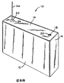
種々の形状および寸法要件を有する小型電子機器の最近の発展は、製造が容易で、これらの電子機器での使用が容易な比較的小型の電気化学電池を必要とする。これらの電池は、例えば、リチウム電池によって供給されるような高エネルギー密度のものが好ましい。広く使用されている一つの形態は、この高エネルギー密度電池を図1に示すような多面体形状のケーシング10に納めている。この電池が、一次電池であるか、二次電池であるかは重要ではない。ケーシング10は平坦な前側壁12と反対側の平坦な後側壁(図示省略)を有し、両者は、右端壁14と反対の左端壁(図示省略)まで延長して、それに会合している。前後側壁および左右端壁は、平坦な底壁(図示省略)まで延長して、これに会合し、深絞りケーシングと呼ばれる単一構造体を形成する。この単一ケースのデザインは、ほぼ直方体をなし、前後側壁が互いに平行であり、左右端壁も互いに平行である。他の構成としては、個々の板を側壁および端壁として互いに連結させて、直方体のケーシングを形成する。
【0003】
いずれの場合にしろ、連結した側壁および端壁は、ほぼ平坦な蓋16によって閉止された開口を形成する。蓋16は、矩形でその周縁においてそれぞれ側壁および端壁の上縁に溶接される。蓋は、充填穴18と端子ピン穴20を有している。充填穴18は、電気化学カップルが収納された後、ケーシングに電解液を注入するための口である。注入穴は、閉止部材、例えば、ボール22をその中にシールすることによって閉止される。
【0004】
端子ピン穴20は、ガラス‐金属シールを支持している。このシールは、端子ピン26を取り巻く絶縁ガラスのリング24からなり、端子ピンの内端(図示省略)は、ケーシングの中に収納されたアノードおよびカソード電極の一方に接続される。このようにして、端子ピン26は、電池のリードの一方として働く。ケーシング10は、ガラス‐金属シール24によって端子ピン26から絶縁され、他方の電極のリードとして働く。
【0005】
【発明が解決しようとする課題】
多面体形状のケーシング10の主な欠点は、電池が人体等の内部に移植されることを意図されているときに、このケーシングは必ずしも最適な形状でないことである。このような場合に、多面体形状のハウジングは、身体内の空間の最善または最も効率的な利用を可能としない。本発明によれば、外郭形状を有するケーシングがより好まれる。
【0006】
複合ケーシング構造がヴュー等に対する米国特許第5,959,088号に記述されている。この特許は、部分的に形をつけた側壁を有する多面体ケーシングを示している。この電池ケーシングは、対向する主側壁を有し、その一方は凹状に湾曲し、他方は反対に凸状に湾曲している。電池の電極は、ケーシングの中に配置され、対向する側壁の湾曲に従うように、スプリング状に曲げられている。このようにして、ケーシングは電池の電極に対して積極的な圧力を維持している。この特許の問題は、対向する側壁が湾曲している一方、中間の周囲端壁が対向する側壁の形状にしたがっていないことである。これによって、この特許のケーシングは完全な輪郭形状が最も望ましい身体内への移植に実用的でない。
【0007】
したがって、多面体ケーシングよりもより密接に身体形状に合致する外形の側壁をもったケーシング内に収容された電池が必要となる。
【0008】
【課題を解決するための手段】
現在、一次リチウム電池は、ペースメーカー、移植可能な細動除去器、神経刺激器、ドラッグポンプのような移植可能な医療機器に使用され、再充填可能なリチウムイオン電池は、補聴器、人工心臓、心臓補助器の動力源として使用されている。これらの電池は、普通、平坦な側壁の、例えば、多面体ケーシングに収容される。しかし、電池の形状は、移植可能な機器にとっては重要である。なぜなら、そのケーシングの形状が、ケーシングの制限的な基準の範囲内で電子機器および補助機器をデザインすることを製造業者に要求している。また、人体の一部、例えば、頭蓋骨を掘削しなければならない場合、従来の多面体電池ケースは、掘削する穴が平坦面の多面体形状に適合するような形であることを要求する。これは、もしケーシングが患者の形態に合致するような形状であれば、必要とされる以上に大きな穴を開ける必要がある。さらに、現在の多面体ケーシングの平坦なデザインは、身体のある場所には、医療機器を移植することを不可能にしている。
【0009】
【発明の実施の形態】
この発明のケーシングは、好ましくは、ニッケル、アルミニウム、ステンレススチール、軟鋼、タンタル、チタンから選ばれた導電性物質から作られる。
【0010】
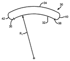
図2〜図4は、本発明による形状の湾曲した対向主側壁を有するケーシングの概略横断面図を示す。図2のケーシング30は、間隔をおいて配置された対向する第1および第2主側壁32および34からなる。各側壁は接点36から38に至る半径R1 によって規定された曲率を有する。半径R1 は第2の側壁34には示されていないが、それは第1の側壁32と同じ半径である。側壁32、34は、湾曲端壁40、42および底壁(図示省略)に延長している。ケーシング30は、蓋(図示省略)によって密封される。
【0011】
図3は、間隔を置いた対向する第1および第2湾曲主側壁52、54からなるケーシング50の他の実施例を示す。第1主側壁52は、接点58から60に至る半径R2 によって規定された第1の湾曲部分56からなる。接点60において、この側壁は、接点60から64に至る半径R3 によって規定された第2の湾曲部分62に移行する。接点64において、この第2の湾曲部分62は、接点64から68に至る半径R4 によって規定された第3の湾曲部分66に移行する。
【0012】
図が示すように、半径R2 の長さは、半径R3 およびR4 の長さよりも短く、半径R4 の長さは半径R3 の長さよりも短い。第2の主側壁54は、その形状ないし湾曲において同様である。側壁52および54は、端壁70、72および底壁(図示省略)まで延長している。ケーシング50は、蓋(図示省略)によって密閉される。
【0013】
それぞれの湾曲部分56、62、66の配置は、どのような順番または方法によって配置を変えても、本発明の範囲内にある。また、一つの側壁は、二つの異なった湾曲部分から形成することもできるし、三つ以上の異なった湾曲部分から形成することもできる。その数および配置は、当該化学電池が使用される具体的な使用態様条件によってのみ制限される。
【0014】
図4は、間隔を置いた対向する第1および第2湾曲主側壁82、84からなるケーシング80の他の実施例を示す。第1主側壁82は、接点88から90に至る半径R5 によって規定された第1の湾曲部分86からなる。接点90において、この側壁は、第1の平坦ないしは真直な部分92に移行する。この第1平坦部分92はそれから接点96から98に至る半径R6 によって規定された第2の湾曲部分94に移行する。接点98において、この側壁82は第2の平坦部分100に移行し、この第2の平坦部分100は、接点104から106に至る半径R7 によって規定された第3の湾曲部分102に移行する。
【0015】
図に示すように、半径R5 、R6 、R7 の長さは、実質上等しい。しかしながら、図3に関して上に述べたように、これは必ずしも必要ではない。平坦部分92、102の長さは等しいが、これもまた、必ずしも必要ではない。側壁には二つよりも多くまたは少ない平坦部分を設けることもできる。そして、これらの部分は、連続してもよいし、互いに角度を付けられてもよいし、互いに一つまたはそれ以上の湾曲部分によって分離されていてもよい。
【0016】
第2の主側壁84は、第1の側壁82と同様の形状である。側壁82、84は、湾曲端壁108、110および底壁(図示省略)まで延長している。このケーシング80も蓋(図示省略)によって密閉されている。
【0017】
図5A、5B、6A、6Bおよび図7は、本発明による外郭を有するケーシング120、160、200をそれぞれ示す。ケーシング120、160は、深絞り構造であり、ケーシング200は、貝殻状外郭を接合した構造である。
【0018】
図5A、図5Bに示すケーシング120は、間隔を置いた対向する前後主側壁122、124を含み、これらの側壁は、湾曲した左右端壁128、126まで延長して、これに会合している。側壁122、124および端壁126、128は、平坦底壁130に連結され、このケーシングを単一の深絞り部材に形成している。前後主側壁122、124は共に、連続した半径の湾曲形状を有し、左右端壁126、128から延長して同じ方向に湾曲している。前後主側壁122、124の曲率は同じであるが、そのことは必ずしも必要ではない。後に詳述するように、あるケーシングのデザインにおいては、前後壁の一方を他方よりも大きい曲率とすることが有利な場合がある。例えば、前壁122を後壁124よりも大きい曲率とすることが有効である。これによって、移植等の目的のためのケーシングの曲率を維持しつつケーシングの内部空間を最適とすることができる。
【0019】
深絞りケーシング120の側壁および端壁は、ほぼ平坦な蓋134によって閉止された開口132を形成している。蓋134は、開口132の周囲形状に合致した周囲形状を有し、凹縁136と反対側の凸縁138によって形成され、これらの縁は、共に左右の湾曲縁140、142まで延長して、これに会合している。これによって、蓋134がケーシングの側壁および端壁の上縁に固定されると、開口132は閉止される。
【0020】
蓋は、充填穴144と端子ピン穴146を有している。充填穴144は、電気化学カップルが収容された後に、ケーシング内に電解液を注入するための穴であり、ボール148のような閉止部材によって密閉される。
【0021】
端子ピン穴146は、端子ピン152を取り巻く絶縁ガラスのリング150からなるガラス‐金属シールを支持している。端子ピン152の内端(図示せず)は、ケーシング内に収容されたアノードとカソード電極の一方に接続されている。このようにして、端子ピン152は、電極リードの一方として働く。ケーシング120は、ガラス‐金属シール150によって端子ピン152から絶縁されており、他方の電極のリードとして働く。
【0022】
図6Aおよび図6Bは、深絞りケーシング160の他の実施例を示す。このケーシングは、間隔を置いた対向する前後主側壁162、164を有し、これらの側壁は、平坦な左右端壁166、168まで延長して、これに会合している。側壁162、164および端壁166、168は、湾曲した底壁170に接続され、このケーシングを単一の深絞り部材に形成している。前後主側壁162、164は共に、連続した半径の湾曲形状を有し、平坦な左右端壁168、166から延長して同じ方向に湾曲している。しかしながら、前後側壁162、164の曲率はケーシング120と同様に等しいが、これは必ずしも必要ではない。
【0023】
深絞りケーシング160の側壁および端壁は、蓋174によって閉止された開口172を形成している。蓋174は、開口172の周囲形状に合致した周囲形状を有し、凹縁176と反対側の凸縁178からなり、この両縁は左右の直縁182、180に延長会合している。これによって、蓋174がケーシングの側壁および端壁の上縁に固定されると、開口172は密閉される。
【0024】
図5Aおよび図5Bのケーシング120と同じように、蓋174は、充填穴184と端子ピン穴186を含んでいる。充填穴184は、電気化学カップルがケーシング内に収容された後に、ケーシング内に電解液を注入するために用いられ、ボール188によって密閉される。
【0025】
端子ピン穴186は、端子ピン192を取り巻く絶縁ガラスのリング190からなるガラス‐金属シールを支持している。端子ピン192の内端(図示せず)は、ケーシング内に収容されたアノードとカソード電極の一方に接続されている。このようにして、端子ピン192は、電極リードの一方として働く。ケーシング120は、ガラス‐金属シール190によって端子ピン192から絶縁されており、他方の電極のリードとして働く。
【0026】
図7は、本発明のケーシング200の他の実施例を示す。このケーシングは第1と第2の貝殻状部分202、204を有し、これらはその周縁において接合密閉可能であって、電極集合体のための密封容器を提供している。第1の貝殻状部分202は、間隔を置いた側壁206、208と、これらが延長会合する間隔を置いた端壁210、212とから構成される周壁を有する。側壁206、208および端壁210、212は、丸い角で会合して、ほぼ凹状の湾曲前壁214まで延長している。この前壁214の反対側には、側壁206、208および端壁210、212の連続縁216がある。
【0027】
第2の貝殻状部分204は、間隔を置いた側壁218、220と、これらが延長会合する間隔を置いた端壁222、224とから構成される周壁を有する。側壁218、220および端壁222、224は、丸い角で会合して、ほぼ凹状の湾曲前壁226まで延長している。この前壁226の反対側には、側壁218、220および端壁222、224の連続縁228がある。
【0028】
貝殻状部分202、204は、その一方の側壁および端壁が、他方のそれらよりも幾分短い寸法に形成されている。これによって、電気化学カップルが短い方の側壁および端壁を有する一方の貝殻に納められた後、他方の貝殻がこれに結合される。この状態で、短い方の側壁および端壁は、他方の貝殻の幾分長い方の側壁および端壁によって短い間隔をおいて部分的にカバーされる。大きい方の貝殻の連続縁216は、他方の貝殻の側壁および端壁に、例えば、溶接によって固定される。これによって、互いに間隔をおいて配置され、同じ方向に湾曲する同じ曲率をもった主凹壁214、226を有するケーシング202に対する密封が行われる。図示されていないが、この電池は、先に述べた電池120、160と同様に、電解液充填穴と、ガラス‐金属シールによってケーシングから絶縁された端子ピンを含んでいる。
【0029】
これらの貝殻は、それがシールされる前に接合されることも本発明の範囲内にある。このことは、貝殻の一方の側壁および端壁が、他方のそれらよりも短くなくて、それらが同じ長さであることを意味する。接合された縁は、例えば、溶接によって密閉される。
【0030】
図8は、ケーシング120内に収容するのに適した外郭形状を有する巻回セルスタックを形成するための巻回マンドレル230を示す。マンドレル230は、輪郭板234に固定されたシャフト232を含んでいる。輪郭板234は、間隔を置いた第1と第2の曲面(面236のみを示す)からなり、これらの曲面は、湾曲端面238、240に延長会合している。望ましくは、第1と第2の面の曲面は、同じ方向に湾曲し、ケーシング120の前後側壁122、124、ケーシング160の前後壁162、164、ケーシング200の湾曲壁214、226の曲率と実質上同じである。
【0031】
図9は、ケーシング120に収容される巻回セルスタックとしての電極集合体を提供するための巻回マンドレル230の使用を示す。セルスタックは、望ましくは、シート状の負電極構造を有し、一次電池ではアノード活物質、または二次電池ではアノード活物質にインターカレートおよび脱インターカレート可能なアノード物質からなる。負電極シートは、一次または二次電池のカソード活物質からなる、好ましくは、シート状の正電極構造体の上に重ね合わされる。負および正電極は、その間にセパレータ物質を介在させることによって、互いに直接物理的接触を阻止されている。好ましい電極活物質シートは、タケウチ等の米国特許第5,435,874号および同第5,571,640号、並びにシーボルト三世等の米国特許第6,174,622号に記載されており、これらの特許は、この発明の譲受人に譲渡され、ここに参考文献として援用する。
【0032】
明確にするため、図9に示す巻回セルスタックは、負および正電極の一方のみを示す。示された電極は、集電体242に接触され、セパレータ包囲体244内に収容された活物質240からなる。電極のいずれの一方を図示するかは、重要ではない。なぜなら、両電極は、その物理的構造において実質上同じであるからである。タブ246が電極の一方、好ましくは、正電極から延長している。
【0033】
図10は、本発明による輪郭を有するケーシングのための巻回セルスタック248の最終形態である。セルスタック248は、他方の電極、好ましくは、負電極から延長するタブ250を含んでいる。これによって、巻回セルスタックが深絞りケーシング120(図11)、もしくは160(図6A)、または図7に示す接合貝殻状部分202、204からなるケーシング200内に収納されると、負電極タブ250は、ケーシングに接続され、正電極タブ246は、端子ピンに接続される。これによって、得られた電池は、ケースが負の構造をなし、ケーシングが負端子であり、ピンが正端子である。ケースが正の構造が望まれる場合は、電極構造は、上述したのと逆となり、正電極タブ250がケーシングに接続され、負電極タブ246が端子ピンに接続される。本発明の重要な特徴は、巻回マンドレルがセルスタックをケーシングの形状に合致させることである。これによって、セルスタックがケーシング内に収容されると、セルスタックに対しては、一緒に巻回されるアノードおよびカソード電極による以外の圧力は加えられない。
【0034】
図12は、本発明の巻回セルスタック252の他の形態を示す。このセルスタックは、電極の一方254、例えば、アノード電極の比較的長い構造体を蛇行状に屈曲させ、他方の電極256、例えば、カソードの板をアノード電極254の屈曲部分の間に配置する。このタイプの電極構造体の詳細な記述については、クライスター等の米国特許第4,964,877号を参照されたい。この特許は、本発明の譲受人に譲渡され、ここに参考文献として援用する。
【0035】
セルスタック248の場合と同様、セルスタック252は、正電極のためのタブ258とカソードプレートのそれぞれのためのタブ260を含んでいる。カソードタブ260は、母線262に接続されている。この母線は、端子ピン(図示せず)に接続されている。このセルスタックは、この発明によるケーシング内に収納される。
【0036】
図13は、間隔を置いた前後主側壁272、274と、これらの側壁が延長会合している左右湾曲端壁276、278とを有するケーシング270の他の実施例を示す。側壁272、274および端壁276、278は、底壁(図示せず)に接続され、単一深絞り部材としてのケーシングを形成する。前後主側壁272、274は、端壁276、278から延長する同一方向に連続湾曲する曲面構造を有している。前壁272の曲率は後壁274の曲率よりも小さい。このことは、前壁272の半径が後壁274の半径よりも大きいことを意味している。
【0037】
深絞りケーシング270の側壁および端壁は、蓋282によって閉止される開口280を形成している。蓋282は、開口280の形状に一致する周囲形状を有している。蓋がケーシングの上縁に固定されると、開口280は閉止される。蓋は電解液注入穴284と端子ピン穴286を含んでいる。注入穴は、ボール288によって閉止され、端子ピン穴286は、アノードおよびカソードの一方のための端子ピン292を取り巻く絶縁ガラスのリング290を支持している。ケーシング270は、電極の端子として働く。
【0038】
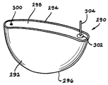
図14は、間隔を置いた対向前後主側壁292、294を有する外郭を有するケーシング290の他の実施例を示す。側壁292、294は、それぞれほぼ半円形をなし、平坦な上縁を有する。側壁292、294は、半円形中間端壁296に延長会合し、端壁296はその全周囲にわたって湾曲して、側壁292、294と会合している。側壁292、294および端壁296は、単一の深絞り部材としてのケーシングを形成している。前後主側壁292、294は、両者とも端壁296から延長し、同じ方向に連続湾曲する曲面形状を有している。
【0039】
深絞りケーシング290の側壁および端壁は、蓋298によって閉止された開口を形成している。この蓋もボール300によって閉止された電解液注入穴284とアノードおよびカソードの一方のための端子ピン304を取り巻く絶縁ガラスのリング302を含んでいる。ケーシング290は、電極の端子として働く。このタイプの電池のさらに詳しい説明は、エリオット等に対する米国特許第5,905,001号を参照されたい。この特許は、本発明の譲受人に譲渡され、ここに参考文献として援用する。
【0040】
先に記述したセルスタック248、252は、固体カソードおよび液体電解質タイプのアルカリ金属/固体カソード、またはアルカリ金属/オキシハライド系のものである。固体カソードタイプの一次電池、例えば、リチウム‐固体カソード電池においては、固体カソード活物質、例えば、酸化バナジウム銀(silver vanadium oxide)、または酸化バナジウム銀銅(copper silver vanadium oxide)が輪郭を有するケーシング内に収容され、例えば、ポリプロピレン繊維またはクロスのようなセパレータによって包囲されている。ここに、固体カソード活物質としては、酸化バナジウム銀、酸化バナジウム銀銅に限定されず、二酸化マンガン、酸化コバルト、酸化ニッケル、酸化銅、硫化銅、硫化鉄、二硫化鉄、二硫化チタン、酸化バナジウム銅、およびこれらの混合物からなる。リチウムは、アノード活物質として望ましい。
【0041】
液体カソード/電解液またはカソード液タイプの電池、例えば、リチウム‐オキシハライド電池において、液体カソライトがケーシング内を満たし、アノード電極および対向する炭素質板の間にはさまれた集電体152からなるカソードエレメントと作用接触している。セパレータがアノードと炭素質カソードの間に配置される。
【0042】
この種の電池のより詳しい記述については、スカースタッド等に対する米国特許第4,246,327号を参照されたい。この特許は、本発明の譲受人に譲渡され、ここに参考文献として援用する。
【0043】
例えば、図示の一次電池において、カソード活物質は、リャン等の米国特許第4,310,609号、同第4,391,729号に記述された酸化バナジウム銀またはタケウチ等の米国特許第5,472,810号、同第5,516,340号に記述された酸化バナジウム銀銅があり、これらの特許は、本発明の譲受人に譲渡され、ここに参考文献として援用する。カソード集電体はチタンであり、端子リード152、192はモリブデンであり、電解液は1,2‐ジメトキシエタンおよび炭酸プロピレンの50:50容積比混合物中のLiAsF6 またはLiPF6 の1.0M〜1.4M溶液であり、ガラスシール58、98はTA‐23ハーメチックシールガラスであり、閉封部材148、188はステンレススチールである。リチウムアノードは、ニッケル箔の集電体の両面に接触されたシート形状であるのが望ましい。
【0044】
二次電気化学電池においては、アノードないし負電極は、アノード活物質にインターカレートおよび脱インターカレート可能な、望ましくは、リチウムのようなアノード物質からなる。炭素質負電極は、種々の形態の炭素、例えば、コークス、グラファイト、アセチレンブラック、カーボンブラック、ガラスカーボン、ヘアリーカーボン等のいずれかからなり、リチウム種を可逆的に保持できるものが望ましい。ヘアリーカーボンは、特に、その比較的高いリチウム保持容量の故に、特に好ましい。ヘアリーカーボンは、タケウチ等の米国特許第5,443,928号に記述された物質であり、この特許は、本発明の譲受人に譲渡され、ここに参考文献として援用する。グラファイトは、他の好ましい物質である。カーボンの形状に係わらず、炭素質物質の繊維が、特に有利である。なぜなら、それらは優秀な機械的性質を有し、これらの物質を反復充電放電サイクル中における劣化に耐え得る固体電極に形成できるからである。その上、炭素繊維の広い表面が急速充放電率を可能にする。
【0045】
二次電池システムにおいては、正電極は望ましくは、空気中で安定であり、取り扱いが容易なリチウム化物質からなることが望ましい。このような空気中で安定なリチウム化カソード活物質の例としては、バナジウム、チタン、クロム、銅、モリブデン、ニオブ、鉄、ニッケル、コバルト、およびマンガンのような金属の酸化物、硫化物、セレン化物、テルル化物がある。より好ましい酸化物としては、LiNiO2 、LiMn2 O4 、LiCoO2 、LiCo0.92Sn0.08O2 、およびLiCo1-x Nix O2 がある。
【0046】
二次電池の望ましい電解質としては、米国特許願09/669,936に記述されたものがある。この特許願は、本発明の譲受人に譲渡され、ここに参考文献として援用する。
【0047】
本発明の思想に対する種々の変形例は、請求の範囲によって規定された本発明の精神および範囲から逸脱しない範囲で、当業者に明らかであろう。
【図面の簡単な説明】
【図1】従来の多面体ケーシング10の斜視図である。
【図2】半径R1 の対向湾曲主側壁を有するケーシングの概略横断面図である。
【図3】異なる半径R2 からR4 の対向湾曲主側壁を有するケーシングの概略横断面図である。
【図4】半径R5 とR6 の対向湾曲主側壁と中間の平坦部分を有するケーシングの概略横断面図である。
【図5】5Aは本発明の深絞りケーシングの一実施例の破断図であり、5Bは5Aのケーシングの側面図である。
【図6】6Aは本発明の深絞りケーシングの一実施例の破断図であり、6Bは6Aのケーシングの側面図である。
【図7】ケーシングの他の実施例の貝殻状ケーシング部分の斜視図である。
【図8】巻回マンドレルの斜視図である。
【図9】図8に示す巻回マンドレルを使用した巻回セルスタックの斜視図である。
【図10】図5A、5Bに示すケーシングに使用される巻回セルスタックの斜視図である。
【図11】図5Aのケーシング内に挿入された図10の巻回セルスタックの斜視図である。
【図12】図6A、6Bに示すケーシングに使用される巻回セルスタックの他の実施例の斜視図である。
【図13】後側壁274よりも大きい半径の前側壁272を有する本発明のケーシング270の他の実施例を示す斜視図である。
【図14】本発明の電池290の他の実施例の立面図である。
【符号の説明】
50 ケーシング
52 第1湾曲主側壁
54 第2湾曲主側壁
56 第1の湾曲部分
58、60、64、68 接点
62 第2の湾曲部分
66 第3の湾曲部分
70、72 端壁[0001]
BACKGROUND OF THE INVENTION
The present invention relates to an electrochemical cell that generates electrical energy by a chemical reaction. More particularly, the present invention relates to an electrochemical cell casing for supplying power to an implantable device. For this purpose, the casing has a surface shape that more closely matches the shape of the body. This facilitates implantation into parts of the body that have not previously been possible due to morphological limitations.
[0002]
[Prior art]
Recent developments in small electronic devices having various shape and dimensional requirements require relatively small electrochemical cells that are easy to manufacture and easy to use in these electronic devices. These batteries are preferably those having a high energy density as supplied by, for example, a lithium battery. In one widely used form, this high energy density battery is housed in a
[0003]
In any case, the connected side walls and end walls form an opening that is closed by a substantially
[0004]
The
[0005]
[Problems to be solved by the invention]
The main disadvantage of the
[0006]
A composite casing structure is described in US Pat. No. 5,959,088 to Vue et al. This patent shows a polyhedral casing having partially shaped side walls. The battery casing has opposing main side walls, one of which is curved in a concave shape and the other is curved in a convex shape on the contrary. The electrode of the battery is placed in the casing and bent in a spring shape to follow the curvature of the opposing side walls. In this way, the casing maintains a positive pressure against the battery electrodes. The problem with this patent is that while the opposing side walls are curved, the middle peripheral end wall does not follow the shape of the opposing side walls. This makes the casing of this patent impractical for implantation into the body where a perfect profile is most desirable.
[0007]
Therefore, there is a need for a battery housed in a casing having an outer sidewall that matches the body shape more closely than a polyhedral casing.
[0008]
[Means for Solving the Problems]
Currently, primary lithium batteries are used in implantable medical devices such as pacemakers, implantable defibrillators, nerve stimulators, drug pumps, and refillable lithium ion batteries are used in hearing aids, artificial hearts, heart Used as a power source for auxiliary equipment. These batteries are usually housed in flat sidewalls, for example in a polyhedral casing. However, the shape of the battery is important for implantable devices. This is because the casing shape requires manufacturers to design electronic and auxiliary equipment within the restrictive standards of the casing. In addition, when a part of the human body, for example, the skull, has to be excavated, the conventional polyhedral battery case requires that the excavation hole has a shape that matches the polyhedral shape of a flat surface. This requires drilling larger holes than necessary if the casing is shaped to match the patient's morphology. Furthermore, the flat design of current polyhedral casings makes it impossible to implant medical devices where the body is.
[0009]
DETAILED DESCRIPTION OF THE INVENTION
The casing of the present invention is preferably made from a conductive material selected from nickel, aluminum, stainless steel, mild steel, tantalum, titanium.
[0010]
2 to 4 show schematic cross-sectional views of a casing having curved opposing main side walls shaped according to the present invention. The
[0011]
FIG. 3 shows another embodiment of a
[0012]
As the figure shows, radius R 2 Is the radius R Three And R Four Shorter than the length of the radius R Four Is the radius R Three Shorter than the length of. The second
[0013]
The arrangement of the
[0014]
FIG. 4 shows another embodiment of a casing 80 consisting of opposed first and second curved main sidewalls 82, 84 spaced apart. The first main side wall 82 has a radius R extending from the contact point 88 to 90. Five The first
[0015]
As shown, radius R Five , R 6 , R 7 Are substantially equal in length. However, as mentioned above with respect to FIG. 3, this is not necessary. The
[0016]
The second main side wall 84 has the same shape as the first side wall 82. The side walls 82 and 84 extend to the
[0017]
5A, 5B, 6A, 6B and FIG. 7
[0018]
The
[0019]
The side walls and end walls of the deep drawn
[0020]
The lid has a filling
[0021]
The
[0022]
6A and 6B show another embodiment of the deep drawn casing 160. The casing has opposed front and rear
[0023]
The side wall and the end wall of the deep-drawn casing 160 form an
[0024]
Like the
[0025]
[0026]
FIG. 7 shows another embodiment of the
[0027]
The second shell-
[0028]
The shell-
[0029]
It is also within the scope of the present invention for these shells to be joined before they are sealed. This means that one side wall and end wall of the shell are not shorter than those of the other and they are the same length. The joined edges are sealed, for example, by welding.
[0030]
FIG. 8 shows a winding
[0031]
FIG. 9 illustrates the use of a
[0032]
For clarity, the wound cell stack shown in FIG. 9 shows only one of the negative and positive electrodes. The electrode shown comprises an
[0033]
FIG. 10 is the final form of a
[0034]
FIG. 12 shows another embodiment of the
[0035]
As with
[0036]
FIG. 13 shows another embodiment of a
[0037]
The side wall and the end wall of the deep-drawn
[0038]
FIG. 14 illustrates another embodiment of a
[0039]
The side wall and the end wall of the deep-drawn
[0040]
The cell stacks 248, 252 described above are of the solid cathode and liquid electrolyte type alkali metal / solid cathode or alkali metal / oxyhalide system. In a solid cathode type primary battery, for example, a lithium-solid cathode battery, a solid cathode active material such as silver vanadium oxide or copper silver vanadium oxide (copper silver vanadium oxide) has a contoured casing. For example, surrounded by a separator such as polypropylene fiber or cloth. Here, the solid cathode active material is not limited to vanadium oxide silver and vanadium oxide silver copper, but manganese dioxide, cobalt oxide, nickel oxide, copper oxide, copper sulfide, iron sulfide, iron disulfide, titanium disulfide, oxidation It consists of vanadium copper and a mixture thereof. Lithium is desirable as the anode active material.
[0041]
In a liquid cathode / electrolyte or catholyte type battery, such as a lithium-oxyhalide battery, a cathode element comprising a
[0042]
For a more detailed description of this type of battery, see US Pat. No. 4,246,327 to Scarstad et al. This patent is assigned to the assignee of the present invention and incorporated herein by reference.
[0043]
For example, in the illustrated primary battery, the cathode active material is selected from US Pat. Nos. 4,310,609 and 4,391,729 to Liang et al. There are vanadium silver and copper oxides described in US Pat. Nos. 472,810 and 5,516,340, which patents are assigned to the assignee of the present invention and incorporated herein by reference. The cathode current collector is titanium, the terminal leads 152, 192 are molybdenum, and the electrolyte is LiAsF in a 50:50 volume ratio mixture of 1,2-dimethoxyethane and propylene carbonate. 6 Or LiPF 6 The glass seals 58 and 98 are TA-23 hermetic seal glass, and the sealing
[0044]
In secondary electrochemical cells, the anode or negative electrode preferably comprises an anode material such as lithium that can be intercalated and deintercalated into the anode active material. The carbonaceous negative electrode is preferably made of various forms of carbon, such as coke, graphite, acetylene black, carbon black, glass carbon, hairy carbon, etc., and can hold lithium species reversibly. Hairy carbon is particularly preferred because of its relatively high lithium retention capacity. Hairy carbon is a material described in US Pat. No. 5,443,928 to Takeuchi et al., Which is assigned to the assignee of the present invention and incorporated herein by reference. Graphite is another preferred material. Regardless of the shape of the carbon, fibers of carbonaceous material are particularly advantageous. Because they have excellent mechanical properties, these materials can be formed into solid electrodes that can withstand degradation during repeated charge and discharge cycles. In addition, the wide surface of the carbon fiber enables a rapid charge / discharge rate.
[0045]
In secondary battery systems, the positive electrode is preferably made of a lithiated material that is stable in air and easy to handle. Examples of such lithiated cathode active materials that are stable in air include oxides, sulfides, and selenium of metals such as vanadium, titanium, chromium, copper, molybdenum, niobium, iron, nickel, cobalt, and manganese. There are chemicals and tellurides. As a more preferred oxide, LiNiO 2 , LiMn 2 O Four LiCoO 2 LiCo 0.92 Sn 0.08 O 2 , And LiCo 1-x Ni x O 2 There is.
[0046]
Preferred electrolytes for secondary batteries include those described in US patent application 09 / 669,936. This patent application is assigned to the assignee of the present invention and incorporated herein by reference.
[0047]
Various modifications to the spirit of the invention will be apparent to those skilled in the art without departing from the spirit and scope of the invention as defined by the claims.
[Brief description of the drawings]
1 is a perspective view of a
Fig. 2 Radius R 1 It is a general | schematic cross-sectional view of the casing which has the opposite curved main side wall.
FIG. 3 Different radii R 2 To R Four It is a general | schematic cross-sectional view of the casing which has the opposite curved main side wall.
FIG. 4 Radius R Five And R 6 It is a general | schematic cross-sectional view of the casing which has an opposing curved main side wall and an intermediate flat part.
FIG. 5A is a cutaway view of one embodiment of the deep-drawn casing of the present invention, and 5B is a side view of the casing of 5A.
6A is a cutaway view of one embodiment of the deep-drawn casing of the present invention, and 6B is a side view of the 6A casing. FIG.
FIG. 7 is a perspective view of a shell-shaped casing portion of another embodiment of the casing.
FIG. 8 is a perspective view of a wound mandrel.
9 is a perspective view of a wound cell stack using the winding mandrel shown in FIG. 8. FIG.
10 is a perspective view of a wound cell stack used in the casing shown in FIGS. 5A and 5B. FIG.
11 is a perspective view of the wound cell stack of FIG. 10 inserted into the casing of FIG. 5A.
12 is a perspective view of another embodiment of the wound cell stack used in the casing shown in FIGS. 6A and 6B. FIG.
13 is a perspective view showing another embodiment of the
14 is an elevational view of another embodiment of a
[Explanation of symbols]
50 casing
52 First Curved Main Side Wall
54 Second curved main side wall
56 First curved portion
58, 60, 64, 68 contacts
62 Second curved portion
66 Third curved portion
70, 72 end wall
Claims (34)
a)負電極と、
b)正電極と、
c)前記負電極および前記正電極を収容するケーシングであって、間隔を置いた第1と第2の主側壁と、これらの側壁が延長会合する対向する第3と第4の端壁とからなり、前記第1と第2の主側壁および前記第3と第4の端壁が底壁から蓋によって閉じられる開口まで延長し、前記第1と第2の主側壁は、それらが前記第3の端壁に結合するところから前記第4の端壁に結合するところまで、および前記底壁から前記開口までのほぼ全域において同じ方向に連続湾曲し、さらに、前記第1と第2の主側壁の少なくとも1つが、異なる第2の曲率に移行している第1の曲率を有しているものと、
d)前記ケーシング内に収納され、前記負電極および正電極を活性化する電解質とからなることを特徴とする電気化学電池。An electrochemical cell,
a) a negative electrode;
b) a positive electrode;
c) a casing for accommodating the negative electrode and the positive electrode, the first and second main side walls being spaced apart from each other, and the third and fourth end walls facing each other, the side walls extending and meeting each other. The first and second main side walls and the third and fourth end walls extend from the bottom wall to an opening closed by a lid, and the first and second main side walls are the third The first and second main side walls are continuously curved in the same direction in almost the entire region from the position connecting to the end wall to the position connecting to the fourth end wall and from the bottom wall to the opening. At least one of which has a first curvature transitioning to a different second curvature ;
d) An electrochemical cell which is housed in the casing and comprises an electrolyte which activates the negative electrode and the positive electrode.
a)負電極と、
b)正電極と、
c)前記負電極および前記正電極を収容するケーシングであって、間隔を置いた第1と第2の主側壁と、これらの側壁が延長会合する中間端壁とからなり、前記第1と第2の主側壁および前記中間端壁が蓋によって閉じられる開口まで延長し、前記第1と第2の主側壁は、それらの夫々が前記中間端壁に結合するところから前記開口までのほぼ全域において同じ方向に連続湾曲し、さらに、前記第1と第2の主側壁の少なくとも一方が、異なる第2の曲率に移行する第1の曲率を有しているものと、
d)前記ケーシング内に収納され、前記負電極および正電極を活性化する電解質とからなることを特徴とする電気化学電池。An electrochemical cell,
a) a negative electrode;
b) a positive electrode;
c) a casing for housing the negative electrode and the positive electrode, the first and second main side walls being spaced apart from each other, and an intermediate end wall where these side walls extend and meet, Two main side walls and the intermediate end wall extend to an opening that is closed by a lid, and the first and second main side walls extend substantially from the point where each of them connects to the intermediate end wall to the opening. Continuously curved in the same direction, and at least one of the first and second main sidewalls has a first curvature that shifts to a different second curvature ;
d) An electrochemical cell which is housed in the casing and comprises an electrolyte which activates the negative electrode and the positive electrode.
a)間隔を置いた第1と第2の主側壁と、これらの側壁が延長会合する対向する第3と第4の端壁とからなっており、前記第1と第2の主側壁および前記第3と第4の端壁は底壁から開口まで延長し、前記第1と第2の主側壁は、それらが前記第3の端壁に結合するところから前記第4の端壁を結合するところまで、および前記底壁から前記開口までのほぼ全域において同じ方向に連続湾曲し、さらに、前記第1と第2の主側壁の少なくとも1つが、異なる第2の曲率に移行している第1の曲率を有しているものと、
b)前記開口を閉止する蓋とからなることを特徴とする電気化学電池のケーシング。An electrochemical cell casing,
a) first and second main side walls spaced apart from each other, and third and fourth end walls facing each other, the side walls extending and meeting, and the first and second main side walls and Third and fourth end walls extend from the bottom wall to the opening, and the first and second main side walls join the fourth end wall from where they join to the third end wall. First, the first and second curved surfaces are continuously curved in the same direction in almost the entire region from the bottom wall to the opening, and at least one of the first and second main side walls is shifted to a different second curvature. With a curvature of
b) A casing for an electrochemical cell comprising a lid for closing the opening.
a)間隔を置いた第1と第2の主側壁と、これらの側壁が延長会合する中間端壁とからなっており、前記第1と第2の主側壁および前記中間端壁は開口まで延長し、前記第1と第2の主側壁は、それらが前記中間端壁に結合するところから前記開口までのほぼ全域において同じ方向に連続湾曲するものと、
b)前記開口を閉止する蓋とからなることを特徴とする電気化学電池のケーシング。An electrochemical cell casing,
a) First and second main side walls spaced from each other, and an intermediate end wall where these side walls extend and meet, and the first and second main side walls and the intermediate end wall extend to the opening. The first and second main side walls are continuously curved in the same direction in almost the entire region from where they are joined to the intermediate end wall to the opening;
b) A casing for an electrochemical cell comprising a lid for closing the opening.
a)間隔を置いた第1と第2の主側壁と、これらの側壁が延長会合する対向する第3と第4の端壁とからなり、前記第1と第2の主側壁および前記第3と第4の端壁が底壁から開口まで延長し、前記第1と第2の主側壁は、それらが前記第3の端壁に結合するところから前記第4の端壁に結合するところまで、および前記底壁から前記開口までのほぼ全域において同じ方向に連続湾曲するケーシングを用意する工程と、
b)前記開口端を通して前記ケーシング内に負電極と正電極を収納する工程と、
c)前記負電極および正電極をそれぞれの端子に接続する工程と、
d)前記開口端を蓋で閉止する工程と、
e)前記蓋または前記ケーシングの充填孔を通して前記ケーシング内に充填した電解質によって前記負電極および正電極を活性化する工程と、
f)前記充填孔を密封する工程
とからなることを特徴とする電気化学電池の製造方法。A method for producing an electrochemical cell, comprising:
a) First and second main side walls spaced apart from each other, and third and fourth end walls facing each other, in which the side walls extend and meet, and the first and second main side walls and the third side wall And the fourth end wall extends from the bottom wall to the opening, and the first and second main side walls extend from where they join to the third end wall to where they join to the fourth end wall. And providing a casing that continuously curves in the same direction in substantially the entire region from the bottom wall to the opening;
b) storing a negative electrode and a positive electrode in the casing through the open end;
c) connecting the negative electrode and the positive electrode to respective terminals;
d) closing the open end with a lid;
e) activating the negative electrode and the positive electrode with the electrolyte filled in the casing through the lid or the filling hole of the casing;
f) A process for producing an electrochemical cell comprising the step of sealing the filling hole.
a)間隔を置いた第1と第2の主側壁と、これらの側壁が延長会合する中間端壁とからなり、前記第1と第2の主側壁および前記中間端壁が開口まで延長し、前記第1と第2の主側壁は、それらが前記中間端壁に結合するところから前記開口に至るまでのほぼ全域において同じ方向に連続湾曲するケーシングを用意する工程と、
b)前記開口端を通して前記ケーシング内に負電極と正電極を収納する工程と、
c)前記負電極および正電極をそれぞれの端子に接続する工程と、
d)前記開口端を蓋で閉止する工程と、
e)蓋またはケーシングの充填孔を通してケーシング内に充填した電解質によって負電極および正電極を活性化する工程と、
f)充填孔を密封する工程
とからなることを特徴とする電気化学電池の製造方法。A method for producing an electrochemical cell, comprising:
a) first and second main sidewalls spaced apart, and an intermediate end wall where these side walls extend, and the first and second main side walls and the intermediate end wall extend to the opening; The first and second main side walls are provided with a casing that curves continuously in the same direction in almost the entire area from where they are joined to the intermediate end wall to the opening;
b) storing a negative electrode and a positive electrode in the casing through the open end;
c) connecting the negative electrode and the positive electrode to respective terminals;
d) closing the open end with a lid;
e) activating the negative and positive electrodes with the electrolyte filled into the casing through the lid or the filling hole of the casing;
f) A method for producing an electrochemical cell comprising the step of sealing the filling hole.
a)間隔を置いた第1と第2の主側壁と、これらの側壁が延長会合する対向する第3と第4の端壁とからなり、前記第1と第2の主側壁および前記第3と第4の端壁が底壁から蓋によって閉止される開口まで延長し、前記第1と第2の主側壁の少なくとも1つが、少なくとも第1と第2の異なる曲率を有し、それらの間に少なくとも1つの中間平坦面が配置され、前記第1と第2の異なる曲率および前記少なくとも1つの中間平坦面がそれぞれ前記底壁から前記開口まで延長しているものと、
b)前記開口端を閉止する蓋とからなることを特徴とする電気化学電池のケーシング。An electrochemical cell casing,
a) First and second main side walls spaced apart from each other, and third and fourth end walls facing each other, in which the side walls extend and meet, and the first and second main side walls and the third side wall And the fourth end wall extends from the bottom wall to an opening closed by a lid, and at least one of the first and second main side walls has at least a first and a second different curvature, between them At least one intermediate flat surface, wherein the first and second different curvatures and the at least one intermediate flat surface each extend from the bottom wall to the opening;
b) A casing for an electrochemical cell comprising a lid for closing the open end.
a)間隔を置いた第1と第2の主側壁と、これらの側壁が延長会合する中間端壁とからなり、前記第1と第2の主側壁および前記中間端壁が開口まで延長し、前記第1と第2の主側壁の少なくとも1つが、第1と第2の異なる曲率を有し、それらの間に少なくとも1つの中間平坦面が配置され、前記第1と第2の異なる曲率および前記少なくとも1つの中間平坦面がそれぞれ前記中間端壁から前記開口まで延長しているものと、
b)前記開口端を閉止する蓋とからなることを特徴とする電気化学電池のケーシング。An electrochemical cell casing,
a) first and second main sidewalls spaced apart, and an intermediate end wall where these side walls extend, and the first and second main side walls and the intermediate end wall extend to the opening; At least one of the first and second main sidewalls has a first and second different curvature, and at least one intermediate flat surface is disposed therebetween, the first and second different curvatures; Each of the at least one intermediate flat surface extending from the intermediate end wall to the opening;
b) A casing for an electrochemical cell comprising a lid for closing the open end.
a)間隔を置いた第1と第2の主側壁と、これらの側壁が延長会合する対向する第3と第4の端壁とからなり、前記第1と第2の主側壁および前記第3と第4の端壁が底壁から蓋によって閉止される開口まで延長し、前記第1と第2の主側壁の少なくとも1つが、それが前記第3の端壁と結合するところから前記第4の端壁と結合するところまで、および前記底壁から前記開口までのほぼ全域にわたって連続的に湾曲しているか、または少なくとも第1と第2の異なる曲率を有し、その間に中間平面が介在され、それぞれ前記底壁から前記開口まで延長しているものと、
b)前記開口を閉止する蓋とからなることを特徴とする電気化学電池のケーシング。An electrochemical cell casing,
a) First and second main side walls spaced apart from each other, and third and fourth end walls facing each other, in which the side walls extend and meet, and the first and second main side walls and the third side wall And the fourth end wall extends from the bottom wall to an opening closed by a lid, and at least one of the first and second main side walls extends from the point where it joins with the third end wall. Are curved continuously over almost the entire area from the bottom wall to the opening, or have at least first and second different curvatures, with an intermediate plane interposed therebetween Each extending from the bottom wall to the opening;
b) A casing for an electrochemical cell comprising a lid for closing the opening.
a)負電極と、
b)正電極と、
c)前記負電極および正電極を収納するケーシングであって、第1の周側壁に延長会合する第1の主側壁を有する第1の部分と、第2の周側壁に延長会合する第2の主側壁を有する第2の部分とからなり、前記第1と第2の部分は、互いに会合して前記第1の周側壁が前記第2の周側壁に接触するものと、
d)前記正電極および前記負電極を活性化するために前記ケーシング内に設けられた電解質とからなることを特徴とする電気化学電池。An electrochemical cell,
a) a negative electrode;
b) a positive electrode;
c) A casing for housing the negative electrode and the positive electrode, the first part having a first main side wall extending and meeting the first peripheral side wall, and the second part extending and meeting the second peripheral side wall A second portion having a main side wall, wherein the first and second portions meet each other so that the first peripheral side wall contacts the second peripheral side wall;
d) An electrochemical cell comprising an electrolyte provided in the casing for activating the positive electrode and the negative electrode.
Applications Claiming Priority (2)
| Application Number | Priority Date | Filing Date | Title |
|---|---|---|---|
| US30664701P | 2001-07-19 | 2001-07-19 | |
| US60/306647 | 2001-07-19 |
Publications (3)
| Publication Number | Publication Date |
|---|---|
| JP2003162985A JP2003162985A (en) | 2003-06-06 |
| JP2003162985A5 JP2003162985A5 (en) | 2006-02-16 |
| JP4377570B2 true JP4377570B2 (en) | 2009-12-02 |
Family
ID=23186224
Family Applications (2)
| Application Number | Title | Priority Date | Filing Date |
|---|---|---|---|
| JP2002242672A Pending JP2003158797A (en) | 2001-07-19 | 2002-07-19 | Outer housing for implantable medical device |
| JP2002242673A Expired - Fee Related JP4377570B2 (en) | 2001-07-19 | 2002-07-19 | Casing with outer shell for electrochemical cell |
Family Applications Before (1)
| Application Number | Title | Priority Date | Filing Date |
|---|---|---|---|
| JP2002242672A Pending JP2003158797A (en) | 2001-07-19 | 2002-07-19 | Outer housing for implantable medical device |
Country Status (6)
| Country | Link |
|---|---|
| US (1) | US7103415B2 (en) |
| EP (1) | EP1277494B1 (en) |
| JP (2) | JP2003158797A (en) |
| AT (1) | ATE460753T1 (en) |
| CA (1) | CA2394387A1 (en) |
| DE (1) | DE60235598D1 (en) |
Cited By (2)
| Publication number | Priority date | Publication date | Assignee | Title |
|---|---|---|---|---|
| KR20190042894A (en) * | 2017-10-17 | 2019-04-25 | 주식회사 엘지화학 | jig for manufacturing secondary battery |
| JP2021524122A (en) * | 2019-04-25 | 2021-09-09 | 寧徳新能源科技有限公司Ningde Amperex Technology Limited | battery |
Families Citing this family (58)
| Publication number | Priority date | Publication date | Assignee | Title |
|---|---|---|---|---|
| US7114502B2 (en) * | 1997-02-26 | 2006-10-03 | Alfred E. Mann Foundation For Scientific Research | Battery-powered patient implantable device |
| US7194302B2 (en) | 2000-09-18 | 2007-03-20 | Cameron Health, Inc. | Subcutaneous cardiac stimulator with small contact surface electrodes |
| US6754528B2 (en) | 2001-11-21 | 2004-06-22 | Cameraon Health, Inc. | Apparatus and method of arrhythmia detection in a subcutaneous implantable cardioverter/defibrillator |
| US6788974B2 (en) * | 2000-09-18 | 2004-09-07 | Cameron Health, Inc. | Radian curve shaped implantable cardioverter-defibrillator canister |
| US7069080B2 (en) | 2000-09-18 | 2006-06-27 | Cameron Health, Inc. | Active housing and subcutaneous electrode cardioversion/defibrillating system |
| US7146212B2 (en) * | 2000-09-18 | 2006-12-05 | Cameron Health, Inc. | Anti-bradycardia pacing for a subcutaneous implantable cardioverter-defibrillator |
| US6721597B1 (en) | 2000-09-18 | 2004-04-13 | Cameron Health, Inc. | Subcutaneous only implantable cardioverter defibrillator and optional pacer |
| US7596408B2 (en) | 2002-12-09 | 2009-09-29 | Medtronic, Inc. | Implantable medical device with anti-infection agent |
| AU2003297723A1 (en) * | 2002-12-09 | 2004-06-30 | Medtronic, Inc. | Reducing relative intermodule motion in a modular implantable medical device |
| US7317947B2 (en) * | 2003-05-16 | 2008-01-08 | Medtronic, Inc. | Headset recharger for cranially implantable medical devices |
| US20050003268A1 (en) * | 2003-05-16 | 2005-01-06 | Scott Erik R. | Battery housing configuration |
| US20050004637A1 (en) * | 2003-05-16 | 2005-01-06 | Ruchika Singhal | Explantation of implantable medical device |
| US7263401B2 (en) * | 2003-05-16 | 2007-08-28 | Medtronic, Inc. | Implantable medical device with a nonhermetic battery |
| US7596399B2 (en) | 2004-04-29 | 2009-09-29 | Medtronic, Inc | Implantation of implantable medical device |
| US20050245984A1 (en) | 2004-04-30 | 2005-11-03 | Medtronic, Inc. | Implantable medical device with lubricious material |
| US7408762B2 (en) * | 2004-07-16 | 2008-08-05 | Cardiac Pacemakers, Inc. | Method and apparatus for providing capacitor feedthrough |
| US7164574B2 (en) | 2004-07-16 | 2007-01-16 | Cardiac Pacemakers, Inc. | Method and apparatus for openings in a capacitor case |
| US7420797B2 (en) * | 2004-07-16 | 2008-09-02 | Cardiac Pacemakers, Inc. | Plug for sealing a capacitor fill port |
| US7075777B2 (en) * | 2004-07-16 | 2006-07-11 | Cardiac Pacemakers, Inc. | Method and apparatus for a capacitor shell including two mateable cupped components |
| DE102005018128A1 (en) * | 2004-10-12 | 2006-04-13 | Restate Patent Ag | Electro-medical implant |
| US7355840B2 (en) * | 2005-05-09 | 2008-04-08 | Cardiac Pacemakers, Inc. | Method and apparatus for a capacitor shell including two mateable cupped components |
| US9084901B2 (en) | 2006-04-28 | 2015-07-21 | Medtronic, Inc. | Cranial implant |
| US7879488B2 (en) * | 2006-08-28 | 2011-02-01 | Cardiac Pacemakers, Inc. | Apparatus and method for a power source casing with a stepped bevelled edge |
| US9008782B2 (en) | 2007-10-26 | 2015-04-14 | Medtronic, Inc. | Occipital nerve stimulation |
| CN201122609Y (en) | 2007-12-03 | 2008-09-24 | 比亚迪股份有限公司 | Battery casing and battery including the same |
| KR101049841B1 (en) * | 2008-03-12 | 2011-07-15 | 주식회사 엘지화학 | Curved battery cell and battery pack comprising the same |
| US9393432B2 (en) | 2008-10-31 | 2016-07-19 | Medtronic, Inc. | Non-hermetic direct current interconnect |
| US20120183825A1 (en) * | 2011-01-14 | 2012-07-19 | Seung-Hun Lee | Secondary battery and method of manufacturing the same |
| GB201202239D0 (en) * | 2012-02-09 | 2012-03-28 | Airbus Operations Ltd | Battery case |
| EP2928551B1 (en) | 2012-12-07 | 2024-02-21 | Medtronic, Inc. | Minimally invasive implantable neurostimulation system |
| US10686209B2 (en) * | 2013-02-21 | 2020-06-16 | Samsung Sdi Co., Ltd. | Electrode assembly, battery cell including the electrode assembly, and method of preparing the battery cell |
| WO2015046751A1 (en) * | 2013-09-30 | 2015-04-02 | 주식회사 엘지화학 | Battery pack having curved surface structure |
| KR101688580B1 (en) * | 2013-09-30 | 2016-12-21 | 주식회사 엘지화학 | Battery Cell with Curved Surface |
| KR20150057819A (en) * | 2013-11-20 | 2015-05-28 | 삼성에스디아이 주식회사 | Rechargeable battery |
| KR20150068759A (en) | 2013-12-12 | 2015-06-22 | 삼성에스디아이 주식회사 | Rechargeable battery |
| KR102143624B1 (en) * | 2014-01-08 | 2020-08-11 | 삼성에스디아이 주식회사 | Secondary battery |
| KR102195733B1 (en) * | 2014-01-20 | 2020-12-28 | 삼성에스디아이 주식회사 | Curved secondary battery |
| KR102198004B1 (en) * | 2014-02-12 | 2021-01-04 | 삼성에스디아이 주식회사 | Battery pack |
| JP2015176789A (en) * | 2014-03-17 | 2015-10-05 | 日立マクセル株式会社 | Nonaqueous electrolyte secondary battery |
| KR102198003B1 (en) * | 2014-04-16 | 2021-01-04 | 삼성에스디아이 주식회사 | Battery pack |
| US20160008605A1 (en) * | 2014-07-11 | 2016-01-14 | Neuropace, Inc. | Integrated backup band for use in forming an enclosure for a medical device |
| USD754131S1 (en) * | 2014-09-01 | 2016-04-19 | Samsung Electronics Co., Ltd. | Portable solid state disk |
| KR102235282B1 (en) * | 2014-11-19 | 2021-04-01 | 삼성에스디아이 주식회사 | Fablicating method of rechargeable battery having a curved surface |
| US9757573B2 (en) | 2014-12-02 | 2017-09-12 | Heraeus Deutschland GmbH & Co. KG | Implantable medical device housing having integrated features |
| KR102296129B1 (en) * | 2014-12-22 | 2021-08-31 | 삼성에스디아이 주식회사 | Secondary battery |
| USD761202S1 (en) * | 2015-02-18 | 2016-07-12 | Everheart Systems, Inc. | Mobile wireless power source |
| KR101879911B1 (en) * | 2015-03-27 | 2018-07-18 | 주식회사 엘지화학 | Method for Production of Curved-Shaped Battery Cell |
| USD792409S1 (en) * | 2015-11-11 | 2017-07-18 | Samsung Electronics Co., Ltd. | External solid state drive |
| KR102094463B1 (en) | 2016-03-24 | 2020-03-30 | 주식회사 엘지화학 | Battery |
| KR102406829B1 (en) * | 2016-04-20 | 2022-06-10 | 삼성전자주식회사 | Solid state drive(SSD) housing and SSD housing assembly |
| US9837682B1 (en) * | 2016-08-29 | 2017-12-05 | Microsoft Technology Licensing, Llc | Variable layer thickness in curved battery cell |
| US10734668B2 (en) | 2016-09-12 | 2020-08-04 | Johnson & Johnson Vision Care, Inc. | Tubular form biomedical device batteries |
| WO2019017668A1 (en) * | 2017-07-18 | 2019-01-24 | 주식회사 엘지화학 | Electrode assembly, secondary battery comprising electrode assembly, and method for manufacturing electrode assembly |
| KR102270872B1 (en) * | 2017-07-18 | 2021-07-01 | 주식회사 엘지에너지솔루션 | electrode assembly, secondary battery and method of manufacturing the same |
| CN109847127A (en) * | 2017-11-30 | 2019-06-07 | 上海微创医疗器械(集团)有限公司 | Magnetic liquid suspension formula centrifugal blood pump |
| EP3603740A1 (en) * | 2018-08-02 | 2020-02-05 | BIOTRONIK SE & Co. KG | Implant |
| EP3603743A1 (en) | 2018-08-02 | 2020-02-05 | BIOTRONIK SE & Co. KG | Implant and method for producing an implant |
| EP3881893A1 (en) | 2020-03-17 | 2021-09-22 | BIOTRONIK SE & Co. KG | Implantable pulse generator comprising an arrangement of two components arranged at an angle to each other |
Family Cites Families (57)
| Publication number | Priority date | Publication date | Assignee | Title |
|---|---|---|---|---|
| US906644A (en) | 1908-05-07 | 1908-12-15 | John B Mears | Tobacco-receptacle. |
| US1402591A (en) | 1921-01-25 | 1922-01-03 | Gallus Charles | Receptacle for storage batteries |
| US2861117A (en) | 1955-05-05 | 1958-11-18 | Pertrix Union Gmbh | Galvanic plate battery |
| US4036227A (en) * | 1973-04-25 | 1977-07-19 | Alza Corporation | Osmotic releasing device having a plurality of release rate patterns |
| US3987799A (en) * | 1973-07-12 | 1976-10-26 | Coratomic Inc. | Heart pacer |
| US3897265A (en) | 1974-01-30 | 1975-07-29 | Gte Laboratories Inc | Electrochemical cells |
| GB1468120A (en) | 1975-01-27 | 1977-03-23 | Timex Corp | Plastics cased primary cells utilizing conductive plastics |
| US4014346A (en) * | 1975-06-26 | 1977-03-29 | Research Corporation | Hermetically sealed cardiac pacer system and recharging system therefor |
| US4057068A (en) * | 1976-02-20 | 1977-11-08 | Medtronic, Inc. | Enclosure for and method of enclosing a body implantable pulse generator |
| US4094321A (en) * | 1977-02-07 | 1978-06-13 | Rudolph Muto | Shallow, dome-shaped pacer with bottom storage means for catheter |
| US4243042A (en) * | 1977-05-04 | 1981-01-06 | Medtronic, Inc. | Enclosure system for body implantable electrical systems |
| US4314562A (en) * | 1977-05-04 | 1982-02-09 | Medtronic, Inc. | Enclosure system for body implantable electrical systems |
| US4157720A (en) * | 1977-09-16 | 1979-06-12 | Greatbatch W | Cardiac pacemaker |
| US4361153A (en) * | 1980-05-27 | 1982-11-30 | Cordis Corporation | Implant telemetry system |
| GB2137801A (en) | 1983-04-04 | 1984-10-10 | Duracell Int | Safe non-venting electrolyte for non-aqueous electrochemical cells |
| JPS60205958A (en) | 1984-03-29 | 1985-10-17 | Matsushita Electric Ind Co Ltd | Sealed storage battery |
| US4761352A (en) | 1985-05-17 | 1988-08-02 | Eastman Kodak Company | Accordian folded electrode assembly |
| US4785827A (en) * | 1987-01-28 | 1988-11-22 | Minnesota Mining And Manufacturing Company | Subcutaneous housing assembly |
| US4894295A (en) | 1988-09-14 | 1990-01-16 | Cheiky Michael C | Metal-alloy air battery |
| US5240788A (en) | 1990-09-04 | 1993-08-31 | Eales George E | Multi-compartment blow molded container |
| WO1992010858A1 (en) | 1990-12-06 | 1992-06-25 | Globe-Union, Inc. | Caseless battery |
| US5674259A (en) * | 1992-10-20 | 1997-10-07 | Gray; Noel Desmond | Multi-focal leadless apical cardiac pacemaker |
| US5439482A (en) * | 1992-04-07 | 1995-08-08 | Angeion Corporation | Prophylactic implantable cardioverter-defibrillator |
| US5326652A (en) | 1993-01-25 | 1994-07-05 | Micron Semiconductor, Inc. | Battery package and method using flexible polymer films having a deposited layer of an inorganic material |
| JP3331649B2 (en) | 1992-12-14 | 2002-10-07 | 日本電池株式会社 | Non-aqueous electrolyte secondary battery |
| US5288565A (en) | 1993-02-08 | 1994-02-22 | Globe-Union Inc. | Support extension for flat pack rechargeable batteries |
| US5411539A (en) * | 1993-08-31 | 1995-05-02 | Medtronic, Inc. | Active can emulator and method of use |
| AU7680594A (en) | 1993-09-01 | 1995-03-22 | Duracell Inc. | Lithium cell with integral annular-shaped ring for reverse polarity protection |
| US5370669A (en) * | 1993-11-17 | 1994-12-06 | Intermedics, Inc. | Implantable cardiac defibrillator with layered package |
| US5486215A (en) | 1993-11-19 | 1996-01-23 | Medtronic, Inc. | Electrode assembly and method |
| JP3387188B2 (en) | 1993-12-29 | 2003-03-17 | ソニー株式会社 | Coin-shaped lithium battery |
| US5486431A (en) | 1994-03-02 | 1996-01-23 | Micron Communications, Inc. | Method of producing button-type batteries and spring-biased concave button-type battery |
| US5549717A (en) | 1994-03-03 | 1996-08-27 | Wilson Greatbatch Ltd. | Method of making prismatic cell |
| JP3015667B2 (en) | 1994-05-31 | 2000-03-06 | 三洋電機株式会社 | Sealed prismatic batteries |
| US5603737A (en) | 1995-06-02 | 1997-02-18 | Pacesetter, Inc. | Electrode structure for electrochemical cell having a rectangular housing |
| US5691073A (en) | 1996-04-10 | 1997-11-25 | Duracell Inc. | Current interrupter for electrochemical cells |
| US6020086A (en) * | 1996-04-11 | 2000-02-01 | U.S. Philips Corporation | Accumulator device for an electric and/or electronic apparatus having a curved shape |
| US5895414A (en) * | 1996-04-19 | 1999-04-20 | Sanchez-Zambrano; Sergio | Pacemaker housing |
| JPH09288996A (en) | 1996-04-23 | 1997-11-04 | Sumitomo Electric Ind Ltd | Nonaqueous electrolyte battery |
| US5716728A (en) | 1996-11-04 | 1998-02-10 | Wilson Greatbatch Ltd. | Alkali metal electrochemical cell with improved energy density |
| JPH10199493A (en) | 1997-01-10 | 1998-07-31 | Japan Storage Battery Co Ltd | Secondary battery |
| JP3634542B2 (en) | 1997-03-07 | 2005-03-30 | 三菱エンジニアリングプラスチックス株式会社 | Battery case for sealed secondary battery |
| US5776169A (en) | 1997-04-28 | 1998-07-07 | Sulzer Intermedics Inc. | Implantable cardiac stimulator for minimally invasive implantation |
| US5926362A (en) | 1997-05-01 | 1999-07-20 | Wilson Greatbatch Ltd. | Hermetically sealed capacitor |
| US6048642A (en) | 1997-06-30 | 2000-04-11 | Lsi Logic Corporation | Adaptive clamping of an electrochemical cell within a replaceable container tray |
| US5905001A (en) * | 1997-08-13 | 1999-05-18 | Wilson Greatbatch Ltd. | Electrode edge design |
| TW385558B (en) | 1998-01-05 | 2000-03-21 | Voltec Pte Ltd | A battery |
| US5958088A (en) | 1998-03-04 | 1999-09-28 | Duracell, Inc. | Prismatic cell construction |
| US6445948B1 (en) | 1998-04-03 | 2002-09-03 | Medtronic, Inc. | Implantable medical device having a substantially flat battery |
| JPH11307130A (en) * | 1998-04-24 | 1999-11-05 | Toshiba Battery Co Ltd | Manufacture of curved battery |
| DE19829637C2 (en) * | 1998-07-02 | 2000-10-19 | Implex Hear Tech Ag | Medical implant |
| US6265102B1 (en) | 1998-11-05 | 2001-07-24 | Electric Fuel Limited (E.F.L.) | Prismatic metal-air cells |
| US6445956B1 (en) * | 1999-10-18 | 2002-09-03 | Abiomed, Inc. | Implantable medical device |
| US6613474B2 (en) | 2000-04-06 | 2003-09-02 | Wilson Greatbatch Ltd. | Electrochemical cell having a casing of mating portions |
| AU2001274813A1 (en) | 2000-04-25 | 2001-11-07 | Polystor Corporation | Custom geometry battery cells and methods and tools for their manufacture |
| US6721597B1 (en) * | 2000-09-18 | 2004-04-13 | Cameron Health, Inc. | Subcutaneous only implantable cardioverter defibrillator and optional pacer |
| US6498951B1 (en) | 2000-10-13 | 2002-12-24 | Medtronic, Inc. | Implantable medical device employing integral housing for a formable flat battery |
-
2002
- 2002-07-19 CA CA002394387A patent/CA2394387A1/en not_active Abandoned
- 2002-07-19 US US10/199,773 patent/US7103415B2/en not_active Expired - Lifetime
- 2002-07-19 DE DE60235598T patent/DE60235598D1/en not_active Expired - Lifetime
- 2002-07-19 EP EP02016127A patent/EP1277494B1/en not_active Expired - Lifetime
- 2002-07-19 JP JP2002242672A patent/JP2003158797A/en active Pending
- 2002-07-19 JP JP2002242673A patent/JP4377570B2/en not_active Expired - Fee Related
- 2002-07-19 AT AT02016127T patent/ATE460753T1/en not_active IP Right Cessation
Cited By (4)
| Publication number | Priority date | Publication date | Assignee | Title |
|---|---|---|---|---|
| KR20190042894A (en) * | 2017-10-17 | 2019-04-25 | 주식회사 엘지화학 | jig for manufacturing secondary battery |
| KR102351243B1 (en) * | 2017-10-17 | 2022-01-17 | 주식회사 엘지에너지솔루션 | jig for manufacturing secondary battery |
| JP2021524122A (en) * | 2019-04-25 | 2021-09-09 | 寧徳新能源科技有限公司Ningde Amperex Technology Limited | battery |
| JP7015915B2 (en) | 2019-04-25 | 2022-02-03 | 寧徳新能源科技有限公司 | battery |
Also Published As
| Publication number | Publication date |
|---|---|
| JP2003162985A (en) | 2003-06-06 |
| CA2394387A1 (en) | 2003-01-19 |
| EP1277494B1 (en) | 2010-03-10 |
| US7103415B2 (en) | 2006-09-05 |
| DE60235598D1 (en) | 2010-04-22 |
| EP1277494A3 (en) | 2005-05-04 |
| JP2003158797A (en) | 2003-05-30 |
| US20030017372A1 (en) | 2003-01-23 |
| EP1277494A2 (en) | 2003-01-22 |
| ATE460753T1 (en) | 2010-03-15 |
Similar Documents
| Publication | Publication Date | Title |
|---|---|---|
| JP4377570B2 (en) | Casing with outer shell for electrochemical cell | |
| US6977124B2 (en) | Contoured casing for an electrochemical cell | |
| US6586134B2 (en) | Electrode lead to case and header, laser/electron beam welding | |
| US6040082A (en) | Volumetrically efficient battery for implantable medical devices | |
| US8313851B2 (en) | Lithium rechargeable battery | |
| US6670074B2 (en) | Glass to metal seal | |
| EP1143540B1 (en) | Cell design for improved energy density | |
| US6361898B1 (en) | Container having a hermetic seal | |
| US7927738B2 (en) | Battery having improved headspace insulator | |
| EP1856749B1 (en) | Implantable battery having thermal shutdown separator | |
| WO2006050393A2 (en) | Folded plate electrode assemblies for battery cathodes | |
| US20210391616A1 (en) | Electrochemical cell | |
| US6933074B2 (en) | Insulative component for an electrochemical cell | |
| US7592097B2 (en) | Electrochemical cell designs with anode plates and connections which facilitate heat dissipation | |
| US10403903B2 (en) | Low-rate battery design | |
| JPH11144742A (en) | Electrode | |
| EP1249879A2 (en) | Low profile battery termination | |
| US11799172B2 (en) | Dual separator design for medical implantable electrochemical cells |
Legal Events
| Date | Code | Title | Description |
|---|---|---|---|
| A621 | Written request for application examination |
Free format text: JAPANESE INTERMEDIATE CODE: A621 Effective date: 20050714 |
|
| A521 | Request for written amendment filed |
Free format text: JAPANESE INTERMEDIATE CODE: A523 Effective date: 20051214 |
|
| RD02 | Notification of acceptance of power of attorney |
Free format text: JAPANESE INTERMEDIATE CODE: A7422 Effective date: 20090126 |
|
| A131 | Notification of reasons for refusal |
Free format text: JAPANESE INTERMEDIATE CODE: A131 Effective date: 20090311 |
|
| A601 | Written request for extension of time |
Free format text: JAPANESE INTERMEDIATE CODE: A601 Effective date: 20090610 |
|
| A602 | Written permission of extension of time |
Free format text: JAPANESE INTERMEDIATE CODE: A602 Effective date: 20090615 |
|
| A521 | Request for written amendment filed |
Free format text: JAPANESE INTERMEDIATE CODE: A523 Effective date: 20090703 |
|
| TRDD | Decision of grant or rejection written | ||
| A01 | Written decision to grant a patent or to grant a registration (utility model) |
Free format text: JAPANESE INTERMEDIATE CODE: A01 Effective date: 20090812 |
|
| A01 | Written decision to grant a patent or to grant a registration (utility model) |
Free format text: JAPANESE INTERMEDIATE CODE: A01 |
|
| A61 | First payment of annual fees (during grant procedure) |
Free format text: JAPANESE INTERMEDIATE CODE: A61 Effective date: 20090911 |
|
| R150 | Certificate of patent or registration of utility model |
Ref document number: 4377570 Country of ref document: JP Free format text: JAPANESE INTERMEDIATE CODE: R150 Free format text: JAPANESE INTERMEDIATE CODE: R150 |
|
| FPAY | Renewal fee payment (event date is renewal date of database) |
Free format text: PAYMENT UNTIL: 20120918 Year of fee payment: 3 |
|
| FPAY | Renewal fee payment (event date is renewal date of database) |
Free format text: PAYMENT UNTIL: 20130918 Year of fee payment: 4 |
|
| R250 | Receipt of annual fees |
Free format text: JAPANESE INTERMEDIATE CODE: R250 |
|
| R250 | Receipt of annual fees |
Free format text: JAPANESE INTERMEDIATE CODE: R250 |
|
| R250 | Receipt of annual fees |
Free format text: JAPANESE INTERMEDIATE CODE: R250 |
|
| R250 | Receipt of annual fees |
Free format text: JAPANESE INTERMEDIATE CODE: R250 |
|
| R250 | Receipt of annual fees |
Free format text: JAPANESE INTERMEDIATE CODE: R250 |
|
| R250 | Receipt of annual fees |
Free format text: JAPANESE INTERMEDIATE CODE: R250 |
|
| R250 | Receipt of annual fees |
Free format text: JAPANESE INTERMEDIATE CODE: R250 |
|
| LAPS | Cancellation because of no payment of annual fees |