JP4377018B2 - Tilt device for ship propulsion equipment - Google Patents
Tilt device for ship propulsion equipment Download PDFInfo
- Publication number
- JP4377018B2 JP4377018B2 JP2000020889A JP2000020889A JP4377018B2 JP 4377018 B2 JP4377018 B2 JP 4377018B2 JP 2000020889 A JP2000020889 A JP 2000020889A JP 2000020889 A JP2000020889 A JP 2000020889A JP 4377018 B2 JP4377018 B2 JP 4377018B2
- Authority
- JP
- Japan
- Prior art keywords
- hydraulic oil
- cylinder
- oil supply
- cylinder devices
- discharge unit
- Prior art date
- Legal status (The legal status is an assumption and is not a legal conclusion. Google has not performed a legal analysis and makes no representation as to the accuracy of the status listed.)
- Expired - Lifetime
Links
Images


Classifications
-
- B—PERFORMING OPERATIONS; TRANSPORTING
- B63—SHIPS OR OTHER WATERBORNE VESSELS; RELATED EQUIPMENT
- B63H—MARINE PROPULSION OR STEERING
- B63H20/00—Outboard propulsion units, e.g. outboard motors or Z-drives; Arrangements thereof on vessels
- B63H20/08—Means enabling movement of the position of the propulsion element, e.g. for trim, tilt or steering; Control of trim or tilt
- B63H20/10—Means enabling trim or tilt, or lifting of the propulsion element when an obstruction is hit; Control of trim or tilt
Description
【0001】
【発明の属する技術分野】
本発明は船舶推進機用チルト装置に関する。
【0002】
【従来の技術】
従来、スターンドライブ型の船舶推進機(船内外機)では、実公平7-36879号公報に記載の如く、船体側ブラケットと、この船体側ブラケットとの間に傾動自在に支持される推進ユニットとの間にシリンダ装置を介装し、作動油給排ユニットからシリンダ装置に作動油を供給及び排出してシリンダ装置を伸縮されることにより、推進ユニットをチルト動作可能としている。
【0003】
従来技術では、左右のシリンダ装置を推進ユニットと船体側ブラケットとの間に介装する一方、作動油給排ユニットを船体内に配置し、作動油給排ユニットから延びる配管を推進ユニットの周辺に延在させて左右のシリンダ装置に接続している。
【0004】
【発明が解決しようとする課題】
従来技術には以下の問題点がある。
▲1▼作動油給排ユニットから延びる配管を推進ユニットの周辺に延在させて左右のシリンダ装置に接続するため、船体と推進ユニットとの間に配管スペースを確保する必要があり、配管作業性が悪い。
【0005】
▲2▼チルト装置の故障時に、作動油給排ユニット及び/又はシリンダ装置の交換とともに、配管の着脱が必要となり、メンテナンス性も悪い。
【0006】
尚、作動油給排ユニットと左右にシリンダ装置を一体化することも考えられるが、両者を単に一体化したときには、加工性、寸法公差のある推進ユニットへの左右のシリンダ装置の取付性において困難がある。また、チルト装置の輸送に際しては、作動油給排ユニットと左右にシリンダ装置とを一体化した大型部品の梱包が必要となり、輸送性も悪い。
【0007】
本発明の課題は、左右一対のシリンダ装置を持つチルト装置において、作動油給排ユニットから左右のシリンダ装置への配管性、メンテナンス性、加工性、推進ユニットへの取付性、輸送性を向上することにある。
【0008】
【課題を解決するための手段】
請求項1に記載の本発明は、船体側ブラケットと、この船体側ブラケットとの間に傾動自在に支持される推進ユニットとの間にシリンダ装置を介装し、作動油給排ユニットからシリンダ装置に作動油を供給及び排出してシリンダ装置を伸縮させることにより、推進ユニットをチルト動作可能とする船舶推進機用チルト装置において、推進ユニットの左右に配置されて互いに別体をなす一対のシリンダ装置と、両シリンダ装置のそれぞれと別体に成形され、且つ両シリンダ装置の間に配置されて両シリンダ装置に結合される作動油給排ユニットとを有し、前記両シリンダ装置のうちの一方のシリンダ装置に作動油給排ユニットを固定し、両シリンダ装置同士を、ジョイントパイプにより結合して一体化し、このジョイントパイプに作動油給排路を設けてなるようにしたものである。
【0009】
請求項2に記載の本発明は、請求項1に記載の本発明において更に、前記シリンダ装置に結合されるジョイントパイプが、当該シリンダ装置に対し単一軸上に設けられてなるようにしたものである。
【0012】
【作用】
請求項1の発明によれば下記(1)〜(7)の作用がある。
(1)作動油給排ユニットを左右のシリンダ装置に結合して一体化したから、船体と推進ユニットとの間に配管スペースを確保する必要がなく、配管作業性が良く、外観性も良い。
【0013】
(2)チルト装置の故障時には、作動油給排ユニット及び/又はシリンダ装置を交換するだけで足り、別途配管の着脱は不要で、メンテナンス性が良い。
【0014】
(3)作動油給排ユニットと左右のシリンダ装置を分割して別体に成形して組立てるものであるから、加工性が良い。また、作動油給排ユニットへのバルブ類の組付性も良い。
【0015】
(4)左右のシリンダ装置と作動油給排ユニットとが別体化された上で結合されて一体化されるものであるから、左右のシリンダ装置の推進ユニットへの取付時に、推進ユニットの寸法公差に対し、左右のシリンダ装置の取付位置(取付間隔L)を修正でき、取付後のシリンダ装置に無理な力の作用がなく、作動のスムースを図ることができる。
【0016】
(5)チルト装置の輸送に際し、作動油給排ユニットと左右のシリンダ装置を分離して梱包でき、輸送性が良い。
【0019】
(6)作動油給排ユニットと両シリンダ装置の間の作動油給排回路を、作動油給排ユニットと一方のシリンダ装置との固定と、両シリンダ装置のジョイントパイプによる結合だけで構築でき、配管作業性を向上できる。
【0020】
(7)両シリンダ装置の相対位置を、両シリンダ装置の間におけるジョイントパイプの結合状態の調整だけにより簡易に調整でき、推進ユニットの寸法公差に対する左右のシリンダ装置の取付位置を簡易に修正できる。
【0021】
請求項2の発明によれば下記(8)の作用がある。
(8)シリンダ装置に結合されるジョイントパイプが当該シリンダ装置に対する単一軸上に設けられたから、当該シリンダ装置をジョイントパイプを回転軸として回転でき、シリンダ装置の取付角度を揺動して調整できる。これにより、推進ユニットの寸法交差に対するシリンダ装置の取付位置を簡易に修正できる。
【0022】
【発明の実施の形態】
図1は船舶推進機を示す模式図、図2はチルト装置を示す要部破断の側面図、図3は図2の平面図、図4は図2の正面図、図5は図2のV-V線に沿う矢視図、図6は図5の各部断面図であり、(A)はA-A線に沿う断面図、(B)はB-B線に沿う断面図、(C)はC-C線に沿う断面図、(D)はD-D線に沿う断面図、図7はシリンダ装置単体を示す側面図、図8は油圧回路図、図9はチルト装置を示す模式図、図10はチルト装置を示す平面図、図11は図10の要部断面図、図12はジョイントパイプを示す端面図である。
【0023】
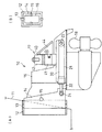
図1は、スターンドライブ型の船舶推進機(船内外機)10であり、船体11に固定されるクランプブラケット12の枠状支持部の上下に支持した鉛直転舵軸13にジョイントブラケット14を転陀可能に支持し、ジョイントブラケット14の枠状支持部の両側部に支持した水平チルト軸15に推進ユニット16をチルト装置17により傾動自在に支持している。ジョイントブラケット14は、本発明の船体側ブラケットを構成する。
【0024】
尚、推進ユニット16は、船体内に配置されているエンジン(不図示)の出力を、伝動軸(不図示)を介して伝達され、プロペラ18を駆動可能としている。
【0025】
然るに、チルト装置17は、左右一対のシリンダ装置20、30を推進ユニット16の両側に配置し、各シリンダ装置20、30をジョイントブラケット14と推進ユニット16の間に介装し、作動油給排ユニット40からシリンダ装置20、30に作動油を供給及び排出し、シリンダ装置20、30を伸縮させることにより、推進ユニット16をチルト動作可能とする。
【0026】
チルト装置17は、図2〜図4に示す如く、シリンダ装置20とシリンダ装置30と作動油給排ユニット40の三者を別個に成形して別体化した上で相互に結合して一体化したものである。即ち、シリンダ装置20とシリンダ装置30は、推進ユニット16の左右に配置される。そして、作動油給排ユニット40は、両シリンダ装置20、30のそれぞれと別体に成形され、且つ両シリンダ装置20、30の間に配置されて両シリンダ装置20、30に結合される。このとき、両シリンダ装置20、30のそれぞれと、作動油給排ユニット40とは、ジョイントパイプ53、55により結合され、このジョイントパイプ53、55に作動油給排路53A、55Aを設けている。
【0027】
シリンダ装置20(シリンダ装置30はシリンダ装置20と対称形をなしているから、シリンダ装置20と同一部分に同一符号を付して説明を省略する)は、図2〜図4、図7に示す如く、アルミ合金鋳物からなるシリンダ21と、シリンダ21に挿入されるピストンロッド22とからなる。シリンダ21は、推進ユニット16のケーシング側部にピン接合される取付部23を備え、ピストンロッド22は、ジョイントブラケット14にピン接合される取付部24を備える。ピストンロッド22は、シリンダ21の内部への挿入端にピストン25を備え、シリンダ21の内部にピストンロッド22を収容する側の第1チルト室26Aと、ピストンロッド22を収容しない側の第2チルト室26Bとを画成する。シリンダ21は、第1チルト室26Aに連通する第1油路27Aと、第2チルト室26Bに連通する第2油路27Bをその上部に穿設される。このとき、シリンダ装置20は、シリンダ21の上部中間部から斜め上方に延び、更に水平方向に延びる折れ曲がり板状のジョイント部28を備え、このジョイント部28に第1油路27A、第2油路27Bを延在し、第1油路27A、第2油路27Bの端部ポートをこのジョイント部28のジョイント面に開口している。
【0028】
尚、シリンダ装置20は、シリンダ21の開口部にピストンロッド22を摺動可能に支持するロッドガイド21Aを備え、ピストン25にアブソーバ弁29を備える。アブソーバ弁29は、推進ユニット16への流木衝突等に際し設定圧で開き、第1チルト室26Aの油を第2チルト室26Bへ移送してピストンロッド22を伸長可能とする。
【0029】
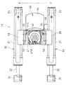
作動油給排ユニット40は、図2〜図6に示す如く、アルミ合金鋳物からなるタンクハウジング41と、タンクハウジング41の上部にボルト41Aにより固定される可逆式モータ42と、タンクハウジング41の下部にボルト41Bにより固定されるアルミ合金鋳物からなる配管プレート43と、タンクハウジング41の側部にボルト41Cにより接続される樹脂製リザーバタンク44により、外観をなす。作動油給排ユニット40は、タンクハウジング41の内部に形成されるタンク45に可逆式ギヤポンプ46を浸漬配置し、モータ42の出力軸をポンプ46の被動軸に接続し、モータ42により駆動されるポンプ46が圧送する作動油を、ポンプ46とタンクハウジング41と配管プレート43に内蔵、穿設してある切換弁付流路47から、シリンダ装置20、30の第1油路27A、第2油路27Bを介して、それらシリンダ装置20、30の第1チルト室26A、第2チルト室26Bに給排可能としている。リザーバタンク44は注油口キャップ48を備え、油路49を介してタンク45に連通されている。
【0030】
ここで、作動油給排ユニット40は、切換弁付流路47を構成する第1接続管路51Aと第2接続管路51Bを配管プレート43に穿設し、第1接続管路51Aと第2接続管路51Bの各1組の端部ポートのそれぞれを配管プレート43の左右両側のジョイント面に開口している。
【0031】
チルト装置17にあっては、作動油給排ユニット40の配管プレート43の左側ジョイント面にシリンダ装置20のジョイント部28のジョイント面を突き合わせ、両者の第1油路27Aの端部ポートと第1接続管路51Aの端部ポートにOリング52A、52Bを介して液密に嵌合する水平配置のジョイントパイプ53により両者を結合し、両者の第2油路27Bの端部ポートと第2接続管路51Bの端部ポートにOリング54A、54B(不図示)を介して液密に嵌合する水平配置のジョイントパイプ55により両者を結合することにより、作動油給排ユニット40とシリンダ装置20とを組立状態とし、それらのジョイントパイプ53、55に作動油給排路53A、55Aを設けている。同時に、作動油給排ユニット40の配管プレート43の右側ジョイント面にシリンダ装置30のジョイント部28のジョイント面を突き合わせ、両者の第1油路27Aの端部ポートと第1接続管路51Aの端部ポートにOリング52A、52Bを介して液密に嵌合するジョイントパイプ53により両者を結合し、両者の第2油路27Bの端部ポートと第2接続管路51Bの端部ポートにOリング54A、54B(不図示)を介して液密に嵌合するジョイントパイプ55により両者を結合することにより、作動油給排ユニット40とシリンダ装置30とを組立状態とし、それらのジョイントパイプ53、55に作動油給排路53A、55Aを設けている。
【0032】
尚、チルト装置17は、作動油給排ユニット40の配管プレート43の左右にシリンダ装置20とシリンダ装置30それぞれのジョイント部28を、ジョイントパイプ53、55の上述の嵌合だけにより接合し、両シリンダ装置20、30により作動油給排ユニット40を挟み込んだ上述の組立状態は、シリンダ装置20とシリンダ装置30の各取付部23、24を推進ユニット16の両側で推進ユニット16、ジョイントブラケット14にピン結合することにより保持される。
【0033】
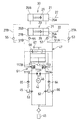
作動油給排ユニット40は、ポンプ46を第1油路27A、第2油路27Bに連絡する切換弁付油路47として、図8に示す如く、シャトル式切換弁61、逆止弁62、63、ダウンブロー弁64、アップブロー弁65、フィルター弁66、手動弁67、サーマルブロー弁68を備える。
【0034】
シャトル式切換弁61は、第1チェック機構付スプール111A、第2チェック機構付スプール111Bの両側に位置する第1逆止弁112A、第2逆止弁112Bを備え、スプール111Aとスプール111Bとを流路113で結んでいる。ポンプ46の正転時には、その送油圧力によって第1逆止弁112Aが開作動するとともに、第1チェック機構付スプール111Aのチェック機構を通る送油圧力が第2チェック機構付スプール111Bを移動させて反対側の第2逆止弁112Bも開作動せしめる。また、ポンプ46の逆転時には、その送油圧力によって第2逆止弁112Bが開作動するとともに、第2チェック機構付スプール111Bのチェック機構を通る送油圧力が第1チェック機構付スプール111Aを移動させて反対側の第1逆止弁112Aも開作動せしめる。
【0035】
逆止弁62は、ポンプ46とタンク45との中間部に介装され、シリンダ装置20、30のチルトアップ操作時に、シリンダ21の内容積がピストンロッド22の退出容積だけ増加して作動油の循環油量が不足することにより、この逆止弁62の開作動により、タンク45からポンプ46に循環油量の不足分を補償するものである。
【0036】
逆止弁63は、ポンプ46とタンク45との中間部に介装され、シリンダ装置20、30のチルトダウン終了時に、チルトダウンが完了し、第2チルト室26Bからポンプ46への返油がなくなった時点で、なおポンプ46が作動する場合に、この逆止弁63の開作動により、タンク45からポンプ46に作動油を供給可能とするものである。
【0037】
ダウンブロー弁64は、シリンダ装置20、30のチルトダウン操作時に、シリンダ21の内容積がピストンロッド22の進入容積だけ減少して作動油の循環油量に余りを生ずるとき、この余った作動油をタンク45に戻すものである。
【0038】
アップブロー弁65は、シリンダ装置20、30のチルトアップ操作時に、ピストン25がロッドガイド21Aに当接しても尚ポンプ46が作動するときに、余剰の作動油をタンク45に戻すものである。
【0039】
フィルター弁66は、推進ユニット16への流木衝突等にアブソーバ弁29の開弁により推進ユニット16が跳ね上がることにより、シリンダ21の内容積がピストンロッド22の退出容積だけ増加したことによる、シリンダ21の負圧分を、フィルター弁66の開作動により、第1チルト室26Aに吸い込んでタンク45から補償するものである。
【0040】
手動弁67は、チルト装置17の故障時等に、手動で操作せしめられ、シリンダ装置20、30を手動で収縮させ、推進ユニット16を手動でチルトダウン操作可能とするものである。
【0041】
サーマルブロー弁68は、シリンダ装置20、30の作動油が温度変化により容積増大したときに、その容積増大した作動油をタンク45に逃がすサーマルブロー機能を果たす。
【0042】
以下、チルト装置17の基本的動作について説明する。
(1) チルトダウン
モータ42及びポンプ46を正転すると、ポンプ46の吐出油はシャトル式切換弁61の第1逆止弁112Aを開作動するとともに、スプール111A、111Bを介して第2逆止弁112Bも開作動せしめる。これにより、ポンプ46の吐出油は第1逆止弁112A、第1油路27Aを通ってシリンダ装置20、30の第1チルト室26Aに供給され、シリンダ装置20、30の第2チルト室26Bの作動油は第2油路27B、第2逆止弁112Bを通ってポンプ46に戻り、シリンダ装置20、30を収縮させ、チルトダウンする。
【0043】
(2) チルトアップ
モータ42及びポンプ46を逆転すると、ポンプ46の吐出油はシャトル式切換弁61の第2チェック弁112Bを開作動するとともに、スプール111A、111Bを介して第1逆止弁112Aも開作動せしめる。これにより、ポンプ46の吐出油は第2逆止弁112B、第2油路27Bを通ってシリンダ装置20、30の第2チルト室26Bに供給され、シリンダ装置20、30の第1チルト室26Aの作動油は第1油路27A、第1逆止弁112Aを通ってポンプ46に戻り、シリンダ装置20、30を伸長させ、チルトアップする。
【0044】
従って、本実施形態によれば、以下の作用がある。
▲1▼作動油給排ユニット40を左右のシリンダ装置20、30に結合して一体化したから、船体11と推進ユニット16との間に配管スペースを確保する必要がなく、配管作業性が良く、外観性も良い。
【0045】
▲2▼チルト装置17の故障時には、作動油給排ユニット40及び/又はシリンダ装置20、30を交換するだけで足り、別途配管の着脱は不要で、メンテナンス性が良い。
【0046】
▲3▼作動油給排ユニット40と左右のシリンダ装置20、30を分割して別体に成形して組立てるものであるから、加工性が良い。また、作動油給排ユニット40へのバルブ類の組付性も良い。
【0047】
▲4▼左右のシリンダ装置20、30と作動油給排ユニット40とが別体化された上で結合されて一体化されるものであるから、左右のシリンダ装置20、30の推進ユニット16への取付時に、推進ユニット16の寸法公差に対し、左右のシリンダ装置20、30の取付位置(取付間隔L等)を修正でき、取付後のシリンダ装置20、30に無理な力の作用がなく、作動のスムースを図ることができる。
【0048】
▲5▼チルト装置17の輸送に際し、作動油給排ユニット40と左右のシリンダ装置20、30を分離して梱包でき、輸送性が良い。
【0049】
▲6▼作動油給排ユニット40と両シリンダ装置20、30の間の作動油給排回路を、両者を結合するジョイントパイプ53、55だけで構築でき、配管作業性を向上できる。
【0050】
▲7▼両シリンダ装置20、30の相対位置を、作動油給排ユニット40に対するジョイントパイプ53、55の結合状態の調整だけにより簡易に調整でき、推進ユニット16の寸法公差に対する左右のシリンダ装置20、30の取付位置を簡易に修正できる。
【0051】
図9(A)はチルト装置17の変形例であり、作動油給排ユニット40において、配管プレート43の部分をタンクハウジング41に一体成形したものである。
【0052】
図9(B)もチルト装置17の本発明例であり、両シリンダ装置20、30のうちの一方のシリンダ装置30のジョイント部28に作動油給排ユニット40のタンクハウジング41をボルト70により固定し、両シリンダ装置20、30のジョイント部28同士を水平配置のジョイントパイプ71、72により結合し、このジョイントパイプ71、72に作動油給排路71A、72Aを設けたものである。シリンダ装置20、30の第1チルト室26A、第2チルト室26Bは、ジョイントパイプ71、72の作動油給排路71A、72Aを介して、作動油給排ユニット40の切換弁付油路47を構成する第1接続管路51A、第2接続管路51Bに接続される。この場合には、シリンダ装置30のジョイント部28に設けられるボルト70の取付部を長孔とすることにより、両シリンダ装置20、30の相対的取付位置(取付間隔L)を調整できる。
【0053】
図9(C)もチルト装置17の変形例であり、作動油給排ユニット40のタンクハウジング41に固定される配管プレート43に推進ユニット16の両側に延びる脚部81、82を設け、両脚部81、82にシリンダ装置20、30のシリンダ21を斜め配置のジョイントパイプ83、84により結合し、このジョイントパイプ83、84に作動油給排路83A、84Aを設けたものである。
【0054】
図9(D)もチルト装置17の変形例であり、作動油給排ユニット40のタンクハウジング41に推進ユニット16の両側に延びる脚部91、92を設け、両脚部91、92にシリンダ装置20、30のシリンダ21を斜め配置のジョイントパイプ93、94により結合し、このジョイントパイプ93、94に作動油給排路93A、94Aを設けたものである。
【0055】
図9(E)もチルト装置17の変形例であり、作動油給排ユニット40のタンクハウジング41の一側に脚部91を設け、脚部91にシリンダ装置20のシリンダ21を斜め配置のジョイントパイプ93、94により結合し、作動油給排ユニット40のタンクハウジング41の他側にシリンダ装置30のシリンダ21を水平配置のジョイントパイプ93、94により結合したものである。
【0056】
尚、図9(C)〜(E)にあっては、シリンダ装置20、30のシリンダ21を斜め配置のジョイントパイプ83、84、93、94によりタンクハウジング41に結合したから、シリンダ装置20、30の取付位置を推進ユニット16の幅方向だけでなく上下方向においても修正できる。
【0057】
図10はチルト装置17の他の変形例であり、一方のシリンダ装置30のシリンダ21に設けたジョイント部28と、作動油給排ユニット40のタンクハウジング41に固定の配管プレート43とを、結合するジョイントパイプ100を、シリンダ装置30に対する単一軸上に設けた。ジョイントパイプ100は、図11、図12に示す如く、小径管100Aと大径管100Bを同軸に備える2重管からなり、小径管100Aの内径を作動油給排路101Aとし、小径管100Aと大径管100Bの環状空間を作動油給排路101Bとし、互いに独立をなす作動油給排路101A、101Bを形成する。小径管100Aの両端部は、ジョイント部28が備える第1油路27Aの端部ポートと配管プレート43が備える第1接続管路51Aの端部ポートにOリング102Aを介して液密に嵌合する。また、大径管100Bの両端部はジョイント部28が備える第2油路27Bの端部ポートと配管プレート43が備える第2接続管路51Bの端部ポートにOリング102Bを介して液密に嵌合する。この変形例によれば、シリンダ装置30に結合されるジョイントパイプ100が当該シリンダ装置30に対する単一軸上に設けられたから、当該シリンダ装置30をジョイントパイプ100を回転軸として回転でき、シリンダ装置30の取付位置を揺動して調整できる。これにより、推進ユニット16の寸法交差に対するシリンダ装置20、30の取付位置を簡易に修正できる。
【0058】
以上、本発明の実施の形態を図面により詳述したが、本発明の具体的な構成はこの実施の形態に限られるものではなく、本発明の要旨を逸脱しない範囲の設計の変更等があっても本発明に含まれる。例えば、本発明のチルト装置は、一対のシリンダ装置と作動油給排ユニットのそれぞれが別体化された上で一体に結合されるものであれば良く、それらの分割数は問わない。
【0059】
【発明の効果】
以上のように本発明によれば、左右一対のシリンダ装置を持つチルト装置において、作動油給排ユニットから左右のシリンダ装置への配管性、メンテナンス性、加工性、推進ユニットへの取付性、輸送性を向上することができる。
【図面の簡単な説明】
【図1】 図1は船舶推進機を示す模式図である。
【図2】 図2はチルト装置を示す要部破断の側面図である。
【図3】 図3は図2の平面図である。
【図4】 図4は図2の正面図である。
【図5】 図5は図2のV-V線に沿う矢視図である。
【図6】 図6は図5の各部断面図であり、(A)はA-A線に沿う断面図、(B)はB-B線に沿う断面図、(C)はC-C線に沿う断面図、(D)はD-D線に沿う断面図である。
【図7】 図7はシリンダ装置単体を示す側面図である。
【図8】 図8は油圧回路図である。
【図9】 図9はチルト装置を示す模式図である。
【図10】 図10はチルト装置を示す平面図である。
【図11】 図11は図10の要部断面図である。
【図12】 図12はジョイントパイプを示す端面図である。
【符号の説明】
10 船舶推進機
14 ジョイントブラケット(船体側ブラケット)
16 推進ユニット
17 チルト装置
20、30 シリンダ装置
40 作動油給排ユニット
53、55 ジョイントパイプ
53A、55A 作動油給排路
71、72 ジョイントパイプ
71A、72A 作動油給排路
100 ジョイントパイプ
101A、101B 作動油給排路[0001]
BACKGROUND OF THE INVENTION
The present invention relates to a tilt device for a marine propulsion device.
[0002]
[Prior art]
Conventionally, in a stern drive type marine propulsion device (inboard / outboard motor), as described in Japanese Utility Model Publication No. 7-36879, a hull side bracket and a propulsion unit that is tiltably supported between the hull side bracket and The propulsion unit can be tilted by interposing a cylinder device therebetween, supplying and discharging hydraulic oil from the hydraulic oil supply / discharge unit to the cylinder device, and expanding and contracting the cylinder device.
[0003]
In the prior art, the left and right cylinder devices are interposed between the propulsion unit and the hull side bracket, while the hydraulic oil supply / discharge unit is arranged in the hull and piping extending from the hydraulic oil supply / discharge unit is provided around the propulsion unit. It is extended and connected to the left and right cylinder devices.
[0004]
[Problems to be solved by the invention]
The prior art has the following problems.
(1) Since piping extending from the hydraulic oil supply / discharge unit extends to the periphery of the propulsion unit and is connected to the left and right cylinder devices, it is necessary to secure a piping space between the hull and the propulsion unit. Is bad.
[0005]
(2) When the tilt device fails, it is necessary to replace the hydraulic oil supply / discharge unit and / or the cylinder device, and to attach and detach the pipes, resulting in poor maintainability.
[0006]
Although it is conceivable to integrate the hydraulic oil supply / discharge unit and the left and right cylinder devices, it is difficult to process the left and right cylinder devices to a propulsion unit with dimensional tolerance when both are simply integrated. There is. Further, when the tilting device is transported, it is necessary to package large parts in which the hydraulic oil supply / discharge unit and the left and right cylinder devices are integrated, and transportability is poor.
[0007]
An object of the present invention is to improve piping performance, maintenance performance, workability, mounting property to a propulsion unit, and transportability from a hydraulic oil supply / discharge unit to left and right cylinder devices in a tilt device having a pair of left and right cylinder devices. There is.
[0008]
[Means for Solving the Problems]
According to the first aspect of the present invention, a cylinder device is interposed between a hull side bracket and a propulsion unit that is tiltably supported between the hull side bracket and the hydraulic oil supply / discharge unit to the cylinder device. by causing expansion of the supply and discharge to the cylinder device hydraulic oil, in tilting device for marine propulsion unit to the propulsion unit tilting operable, a pair of cylinder devices which form a separate from each other are disposed on the right and left propulsion units And a hydraulic oil supply / discharge unit that is molded separately from each of the two cylinder devices and is disposed between the two cylinder devices and coupled to the two cylinder devices, and one of the two cylinder devices. The hydraulic oil supply / discharge unit is fixed to the cylinder device, and both cylinder devices are joined together by a joint pipe, and the hydraulic oil supply / discharge passage is connected to this joint pipe. It is obtained by the so provided.
[0009]
According to a second aspect of the present invention, in the first aspect of the present invention, a joint pipe coupled to the cylinder device is provided on a single axis with respect to the cylinder device. is there.
[0012]
[Action]
The invention according to claim 1 has the following actions (1) to (7) .
(1) Since the hydraulic oil supply / discharge unit is combined and integrated with the left and right cylinder devices, it is not necessary to secure a piping space between the hull and the propulsion unit, and the piping workability is good and the appearance is also good.
[0013]
(2) When the tilting device fails, it is only necessary to replace the hydraulic oil supply / discharge unit and / or the cylinder device.
[0014]
(3) Workability is good because the hydraulic oil supply / discharge unit and the left and right cylinder devices are divided and molded separately. Also, the assembly of valves to the hydraulic oil supply / discharge unit is good.
[0015]
(4) Since the left and right cylinder devices and the hydraulic oil supply / discharge unit are separated and combined to be integrated, the dimensions of the propulsion unit must be set when the left and right cylinder devices are attached to the propulsion unit. The mounting positions (mounting intervals L) of the left and right cylinder devices can be corrected with respect to the tolerance, and there is no excessive force applied to the cylinder devices after mounting, so that the operation can be performed smoothly.
[0016]
(5) When the tilting device is transported, the hydraulic oil supply / discharge unit and the left and right cylinder devices can be separated and packaged, and transportability is good.
[0019]
(6) The hydraulic oil supply / discharge circuit between the hydraulic oil supply / discharge unit and both cylinder devices can be constructed only by fixing the hydraulic oil supply / discharge unit and one cylinder device, and by connecting the joint pipes of both cylinder devices, Piping workability can be improved.
[0020]
(7) The relative positions of both cylinder devices can be easily adjusted only by adjusting the coupling state of the joint pipe between the two cylinder devices, and the mounting positions of the left and right cylinder devices can be easily corrected with respect to the dimensional tolerance of the propulsion unit.
[0021]
The invention according to claim 2 has the following effect (8) .
(8) Since the joint pipe coupled to the cylinder device is provided on a single axis with respect to the cylinder device, the cylinder device can be rotated about the joint pipe as a rotation shaft, and the mounting angle of the cylinder device can be adjusted by swinging. Thereby, the mounting position of the cylinder device with respect to the dimension crossing of the propulsion unit can be easily corrected.
[0022]
DETAILED DESCRIPTION OF THE INVENTION
1 is a schematic view showing a marine propulsion device, FIG. 2 is a side view of a tilted portion showing a tilt device, FIG. 3 is a plan view of FIG. 2, FIG. 4 is a front view of FIG. 6 is a cross-sectional view of each part of FIG. 5, (A) is a cross-sectional view along the AA line, (B) is a cross-sectional view along the BB line, and (C) is a cross-sectional view along the CC line. FIG. 7D is a cross-sectional view taken along line DD, FIG. 7 is a side view showing the cylinder device alone, FIG. 8 is a hydraulic circuit diagram, FIG. 9 is a schematic diagram showing the tilt device , and FIG. 10 is a plan view showing the tilt device . 11 is a cross-sectional view of the main part of FIG. 10, and FIG. 12 is an end view showing the joint pipe.
[0023]
FIG. 1 shows a stern drive type marine propulsion device (inboard / outboard motor) 10, which rotates a
[0024]
The
[0025]
However, the
[0026]
As shown in FIGS. 2 to 4, the
[0027]
The cylinder device 20 (the
[0028]
The
[0029]
2 to 6, the hydraulic oil supply /
[0030]
Here, the hydraulic oil supply /
[0031]
In the
[0032]
The
[0033]
As shown in FIG. 8, the hydraulic oil supply /
[0034]
The shuttle
[0035]
The
[0036]
The
[0037]
When the
[0038]
The up-
[0039]
The
[0040]
The
[0041]
The
[0042]
Hereinafter, the basic operation of the
(1) When the tilt-
[0043]
(2) When the tilt-up
[0044]
Therefore, according to the present embodiment, there are the following operations.
(1) Since the hydraulic oil supply /
[0045]
(2) When the
[0046]
(3) Since the hydraulic oil supply /
[0047]
(4) Since the left and
[0048]
(5) When the
[0049]
(6) The hydraulic oil supply / discharge circuit between the hydraulic oil supply /
[0050]
(7) The relative positions of both
[0051]
FIG. 9A shows a modification of the
[0052]
FIG. 9B is also an example of the present invention of the
[0053]
FIG. 9C is also a modification of the
[0054]
FIG. 9D is also a modification of the
[0055]
FIG. 9E is also a modification of the
[0056]
9C to 9E, since the
[0057]
FIG. 10 shows another modification of the
[0058]
The embodiment of the present invention has been described in detail with reference to the drawings. However, the specific configuration of the present invention is not limited to this embodiment, and there are design changes and the like without departing from the gist of the present invention. Is included in the present invention. For example, the tilt device of the present invention may be any device as long as the pair of cylinder devices and the hydraulic oil supply / discharge unit are separated and combined together, and the number of divisions is not limited.
[0059]
【The invention's effect】
As described above, according to the present invention, in a tilt device having a pair of left and right cylinder devices, piping performance, maintenance performance, workability, propulsion unit mounting properties, transportation from the hydraulic oil supply / discharge unit to the left and right cylinder devices Can be improved.
[Brief description of the drawings]
FIG. 1 is a schematic diagram showing a ship propulsion device.
FIG. 2 is a side view of a main part fracture showing a tilt device.
FIG. 3 is a plan view of FIG. 2;
FIG. 4 is a front view of FIG. 2;
FIG. 5 is a view taken along the line VV in FIG. 2;
6 is a cross-sectional view of each part of FIG. 5, (A) is a cross-sectional view along the AA line, (B) is a cross-sectional view along the BB line, (C) is a cross-sectional view along the CC line, D) is a sectional view taken along the line DD.
FIG. 7 is a side view showing a single cylinder device.
FIG. 8 is a hydraulic circuit diagram.
FIG. 9 is a schematic diagram showing a tilt device .
FIG. 10 is a plan view showing a tilt device .
FIG. 11 is a cross-sectional view of a main part of FIG.
FIG. 12 is an end view showing the joint pipe.
[Explanation of symbols]
10
16
20 , 30
Claims (2)
推進ユニットの左右に配置されて互いに別体をなす一対のシリンダ装置と、両シリンダ装置のそれぞれと別体に成形され、且つ両シリンダ装置の間に配置されて両シリンダ装置に結合される作動油給排ユニットとを有し、
前記両シリンダ装置のうちの一方のシリンダ装置に作動油給排ユニットを固定し、両シリンダ装置同士を、ジョイントパイプにより結合して一体化し、このジョイントパイプに作動油給排路を設けてなることを特徴とする船舶推進機用チルト装置。A cylinder device is interposed between the hull side bracket and the propulsion unit supported to be tiltable between the hull side bracket, and the hydraulic oil is supplied to and discharged from the hydraulic oil supply / discharge unit to the cylinder device. by causing expansion of the device, the tilting device for marine propulsion unit to the propulsion unit tilting operable,
A pair of cylinder devices arranged on the left and right sides of the propulsion unit and separate from each other , and hydraulic oil formed separately from both cylinder devices and disposed between both cylinder devices and coupled to both cylinder devices A supply / discharge unit ,
A hydraulic oil supply / discharge unit is fixed to one of the two cylinder devices, and both cylinder devices are joined together by a joint pipe, and a hydraulic oil supply / discharge passage is provided in the joint pipe. A tilting device for a marine propulsion device.
Priority Applications (3)
| Application Number | Priority Date | Filing Date | Title |
|---|---|---|---|
| JP2000020889A JP4377018B2 (en) | 2000-01-28 | 2000-01-28 | Tilt device for ship propulsion equipment |
| US09/693,594 US6454619B1 (en) | 2000-01-28 | 2000-10-20 | Tilt device for marine propulsion unit |
| KR1020000065148A KR100590365B1 (en) | 2000-01-28 | 2000-11-03 | Tilt device for marine propulsion unit |
Applications Claiming Priority (1)
| Application Number | Priority Date | Filing Date | Title |
|---|---|---|---|
| JP2000020889A JP4377018B2 (en) | 2000-01-28 | 2000-01-28 | Tilt device for ship propulsion equipment |
Publications (2)
| Publication Number | Publication Date |
|---|---|
| JP2001206291A JP2001206291A (en) | 2001-07-31 |
| JP4377018B2 true JP4377018B2 (en) | 2009-12-02 |
Family
ID=18547376
Family Applications (1)
| Application Number | Title | Priority Date | Filing Date |
|---|---|---|---|
| JP2000020889A Expired - Lifetime JP4377018B2 (en) | 2000-01-28 | 2000-01-28 | Tilt device for ship propulsion equipment |
Country Status (3)
| Country | Link |
|---|---|
| US (1) | US6454619B1 (en) |
| JP (1) | JP4377018B2 (en) |
| KR (1) | KR100590365B1 (en) |
Families Citing this family (6)
| Publication number | Priority date | Publication date | Assignee | Title |
|---|---|---|---|---|
| US6962166B2 (en) * | 2002-02-19 | 2005-11-08 | Teleflex Canada Limited Partnership | Hydraulic fluid reservoir and hydraulic system |
| JP4101025B2 (en) * | 2002-11-06 | 2008-06-11 | 株式会社ショーワ | Marine gas cylinder device |
| US8608441B2 (en) | 2006-06-12 | 2013-12-17 | Energyield Llc | Rotatable blade apparatus with individually adjustable blades |
| US8858279B1 (en) | 2011-05-31 | 2014-10-14 | Brp Us Inc. | Tilt/trim and steering bracket assembly for a marine outboard engine |
| US9499247B1 (en) * | 2011-05-31 | 2016-11-22 | Brp Us Inc. | Marine outboard engine having a tilt/trim and steering bracket assembly |
| US8851944B1 (en) | 2012-12-20 | 2014-10-07 | Brp Us Inc. | Marine engine hydraulic system |
Family Cites Families (12)
| Publication number | Priority date | Publication date | Assignee | Title |
|---|---|---|---|---|
| US3885517A (en) * | 1973-01-04 | 1975-05-27 | Outboard Marine Corp | Power trim-tilt system |
| DE2655126C3 (en) * | 1976-12-04 | 1979-07-26 | Bayerische Motoren Werke Ag, 8000 Muenchen | Propulsion for water vehicles |
| US4362514A (en) | 1980-09-04 | 1982-12-07 | Outboard Marine Corporation | High performance stern drive unit |
| JPH02102892A (en) * | 1988-10-12 | 1990-04-16 | Sanshin Ind Co Ltd | Trimming and tilting device for marine propulsive unit |
| JP3124577B2 (en) * | 1991-06-07 | 2001-01-15 | ヤマハ発動機株式会社 | Tilt device for ship propulsion |
| JPH0736879A (en) | 1993-06-28 | 1995-02-07 | Ricoh Co Ltd | 'kana'/'kanji' conversion control device and its control method |
| US5707263A (en) * | 1996-05-31 | 1998-01-13 | Brunswick Corporation | Adjustable trim position system |
| JP3947258B2 (en) * | 1997-01-17 | 2007-07-18 | ヤマハモーターパワープロダクツ株式会社 | Vertical swing device for marine propulsion device |
| JPH11105790A (en) * | 1997-09-30 | 1999-04-20 | Showa Corp | Tilt and trim device of marine propulsion machine |
| US6146220A (en) * | 1999-08-30 | 2000-11-14 | Brunswick Corporation | Pedestal mount for an outboard motor |
| US6183321B1 (en) * | 1999-08-30 | 2001-02-06 | Brunswick Corporation | Outboard motor with a hydraulic pump and an electric motor located within a steering mechanism |
| US6296535B1 (en) * | 1999-12-21 | 2001-10-02 | Bombardier Motor Corporation Of America | Tilt-trim subsystem for boats using a stern drive system |
-
2000
- 2000-01-28 JP JP2000020889A patent/JP4377018B2/en not_active Expired - Lifetime
- 2000-10-20 US US09/693,594 patent/US6454619B1/en not_active Expired - Fee Related
- 2000-11-03 KR KR1020000065148A patent/KR100590365B1/en not_active IP Right Cessation
Also Published As
| Publication number | Publication date |
|---|---|
| US6454619B1 (en) | 2002-09-24 |
| KR20010077914A (en) | 2001-08-20 |
| KR100590365B1 (en) | 2006-06-15 |
| JP2001206291A (en) | 2001-07-31 |
Similar Documents
| Publication | Publication Date | Title |
|---|---|---|
| JP6648057B2 (en) | Large outboard motor for ship, method of manufacturing and operating method thereof | |
| JP5687926B2 (en) | Trim and tilt device for marine propulsion equipment | |
| US7255616B1 (en) | Steering system for a marine propulsion device | |
| JP4036512B2 (en) | Tilt device for ship propulsion equipment | |
| US9266421B2 (en) | Cooling system structure for vehicular water-cooled internal combustion engine | |
| JP4377018B2 (en) | Tilt device for ship propulsion equipment | |
| US9233743B2 (en) | Steering device of outboard motor | |
| US20050215130A1 (en) | Marine propulsion unit | |
| JP2009149186A (en) | Outboard motor | |
| JP3945878B2 (en) | Trim and tilt device for marine propulsion equipment | |
| JP4132440B2 (en) | Trim and tilt device for marine propulsion equipment | |
| US6325686B1 (en) | Tilt device for marine propulsion unit | |
| US11333058B2 (en) | Marine outboard motor with drive shaft and cooling system | |
| KR100472820B1 (en) | Trim-tilt device for marine propulsion unit | |
| US7641527B1 (en) | Marine outboard engine exhaust system | |
| JP2012254702A (en) | Shift apparatus of outboard motor | |
| JP2013180602A (en) | Tilt device for vessel propulsion machine | |
| JP2012218500A (en) | Outboard motor | |
| US10124872B2 (en) | Shifting device for outboard motor | |
| JP2000255491A (en) | Engine mount structure of engine for small ship | |
| JP2012218684A (en) | Propeller supporting structure of outboard motor | |
| JP2001030994A (en) | Trim-tilt device for ship propulsion engine | |
| JP2001001989A (en) | Trim tilt device for marine propeller | |
| JPH0217396B2 (en) | ||
| JPH04232193A (en) | Tilting device of outboard motor |
Legal Events
| Date | Code | Title | Description |
|---|---|---|---|
| A621 | Written request for application examination |
Free format text: JAPANESE INTERMEDIATE CODE: A621 Effective date: 20061205 |
|
| A131 | Notification of reasons for refusal |
Free format text: JAPANESE INTERMEDIATE CODE: A131 Effective date: 20081209 |
|
| A977 | Report on retrieval |
Free format text: JAPANESE INTERMEDIATE CODE: A971007 Effective date: 20081211 |
|
| A521 | Written amendment |
Free format text: JAPANESE INTERMEDIATE CODE: A523 Effective date: 20090206 |
|
| TRDD | Decision of grant or rejection written | ||
| A01 | Written decision to grant a patent or to grant a registration (utility model) |
Free format text: JAPANESE INTERMEDIATE CODE: A01 Effective date: 20090908 |
|
| A01 | Written decision to grant a patent or to grant a registration (utility model) |
Free format text: JAPANESE INTERMEDIATE CODE: A01 |
|
| A61 | First payment of annual fees (during grant procedure) |
Free format text: JAPANESE INTERMEDIATE CODE: A61 Effective date: 20090910 |
|
| R150 | Certificate of patent or registration of utility model |
Free format text: JAPANESE INTERMEDIATE CODE: R150 |
|
| FPAY | Renewal fee payment (event date is renewal date of database) |
Free format text: PAYMENT UNTIL: 20120918 Year of fee payment: 3 |