JP4376756B2 - Disk unit - Google Patents
Disk unit Download PDFInfo
- Publication number
- JP4376756B2 JP4376756B2 JP2004327832A JP2004327832A JP4376756B2 JP 4376756 B2 JP4376756 B2 JP 4376756B2 JP 2004327832 A JP2004327832 A JP 2004327832A JP 2004327832 A JP2004327832 A JP 2004327832A JP 4376756 B2 JP4376756 B2 JP 4376756B2
- Authority
- JP
- Japan
- Prior art keywords
- slider
- disk
- lever
- traverse
- discharge
- Prior art date
- Legal status (The legal status is an assumption and is not a legal conclusion. Google has not performed a legal analysis and makes no representation as to the accuracy of the status listed.)
- Active
Links
Images


Landscapes
- Feeding And Guiding Record Carriers (AREA)
Description
本発明は、CDやDVDなどのディスク状の記録媒体への記録、または再生を行うディスク装置に関し、特に外部からディスクを直接挿入し、または直接排出できる、いわゆるスロットイン方式のディスク装置に関する。 The present invention relates to a disk device that performs recording or reproduction on a disk-shaped recording medium such as a CD or DVD, and more particularly to a so-called slot-in type disk device that can directly insert or eject a disk from the outside.
従来のディスク装置は、トレイまたはターンテーブル上にディスクを載置し、このトレイやターンテーブルを装置本体内に装着するローディング方式が多く採用されているが、このようなローディング方式では、トレイやターンテーブルが必要な分、ディスク装置本体を薄型化するには限度があった。このため、最近では、ローディングモータによりレバー等でディスクを直接操作する、いわゆるスロットイン方式のディスク装置が存在する。
しかしこのようなスロットイン方式のディスク装置では、ディスク装置本体の薄型化や小型化を図ることは可能であったが、ローディングモータにより駆動されるメカニズムによってディスクの出し入れを行うため、薄型化を優先するあまりに、ローディングモータの異常停止時(異常電源OFFなど)にディスクが容易に取り出せないという課題があった。
特許文献1に開示されている従来技術では、ローディングモータの異常停止時(異常電源OFFなど)に対応できるような工夫は見られるが、ディスク取り出し操作に多大の労力を必要とし、容易に取り出すことが困難であった。
However, in such a slot-in type disk device, it was possible to reduce the thickness and size of the disk device main body, but since the disk is loaded and unloaded by a mechanism driven by a loading motor, the thinning is prioritized. Therefore, there is a problem that the disk cannot be easily taken out when the loading motor stops abnormally (such as when the abnormal power is turned off).
Although the conventional technique disclosed in Patent Document 1 can be devised to cope with an abnormal stop of the loading motor (such as abnormal power OFF), it requires a lot of labor for the disk ejecting operation and can be easily ejected. It was difficult.
本発明は、ディスク装置本体の薄型化や小型化を図りつつ、ディスクの出し入れを行うローディングモータの異常停止時(異常電源OFFなど)にもディスクが比較的容易に取り出すことが出来、迅速なトラブル対処ができるディスク装置を提供することを目的とする。 The present invention makes it possible to take out the disk relatively easily even when the loading motor for taking in and out the disk is abnormally stopped (such as abnormal power off) while reducing the thickness and size of the disk device body. An object of the present invention is to provide a disk device capable of coping with the problem.
請求項1記載の本発明のディスク装置は、ベース本体と蓋体とからシャーシ外装を構成し、前記シャーシ外装のフロント面にディスクを直接挿入するディスク挿入口を形成するとともに前記シャーシ外装のリア面にコネクタを配設し、前記ベース本体にトラバースとプリント基板とを設け、スピンドルモータとピックアップと前記ピックアップを移動させる駆動手段とを前記トラバースによって保持し、前記ディスク挿入口側に前記トラバースを、前記コネクタ側に前記プリント基板をそれぞれ配置し、前記トラバースに支持された前記スピンドルモータが前記ベース本体側と前記蓋体側との間で移動可能に前記トラバースを変位させるトラバース移動手段を設け、前記トラバース移動手段は、シャーシ外装のフロント面近傍に設けたローディングモータと、このローディングモータの駆動軸とギア群を介して連結され、前記ローディングモータの駆動によって長手方向に摺動するメインスライダーと、前記メインスライダーに設けたカム機構によって構成し、前記メインスライダーを、前記スピンドルモータの側方に、その一端が前記フロント面側、その他端が前記リア面側となる方向に配設し、前記メインスライダーと同一方向を長手方向とする排出スライダーを、リンクアームを介して前記メインスライダーと連結し、前記排出スライダーを、前記ベース本体の一端のリア面側に配置し、前記ベース本体の一端のリア面側には、排出レバーを設け、前記ベース本体の他端のフロント側には、引き込みレバーを設け、前記排出レバーは、前記排出スライダーの移動にともなって回動動作し、前記引き込みレバーは、前記メインスライダーの移動にともなって旋回動作し、前記メインスライダーの動作によって前記引き込みレバーを前記ディスクに接触しない位置に回動させるディスク装置であって、前記シャーシ外装のフロント面の一端に、棒状体を挿入可能な開口部を設け、前記開口部に対向する位置に前記排出スライダーが配置され、前記棒状体の前記開口部からの操作方向と、前記排出スライダーの排出動作時の操作方向とを一致させ、前記棒状体の挿入によって、前記排出スライダーが移動することで前記リンクアームが回転移動するとともに前記メインスライダーが摺動し、前記メインスライダーに設けた前記カム機構によって前記トラバースが移動し、前記排出レバーは、前記排出スライダーの動作によって回動して前記ディスクを排出することを特徴とする。 According to a first aspect of the present invention, there is provided a disk device comprising a base body and a lid, and forming a chassis exterior, forming a disk insertion slot for directly inserting a disk on a front surface of the chassis exterior, and a rear surface of the chassis exterior. The base body is provided with a traverse and a printed circuit board, a spindle motor, a pickup, and a driving means for moving the pickup are held by the traverse, and the traverse is placed on the disk insertion port side, The printed circuit board is disposed on each connector side, and a traverse moving means is provided for displacing the traverse so that the spindle motor supported by the traverse can move between the base main body side and the lid body side. The means is a loader provided near the front surface of the chassis exterior. A main slider that is connected to the loading motor via a drive shaft and a gear group, and that slides in the longitudinal direction by the driving of the loading motor, and a cam mechanism provided on the main slider. A discharge slider having a longitudinal direction in the same direction as the main slider is disposed on the side of the spindle motor in a direction in which one end is the front surface side and the other end is the rear surface side. The discharge slider is disposed on the rear surface side of one end of the base body, a discharge lever is provided on the rear surface side of one end of the base body, and the other end of the base body is connected to the main slider A pull-in lever is provided on the front side of the printer, and the discharge lever moves with the movement of the discharge slider. And dynamic operation, the pull-in lever, the pivot operation with the movement of the main slider, a disk device to rotate the front Symbol pull lever by the operation of the main slider to the position that does not contact the disk, At one end of the front surface of the chassis exterior, an opening for inserting a rod-shaped body is provided, the discharge slider is disposed at a position facing the opening, and the operation direction of the rod-shaped body from the opening, The operation direction during the discharge operation of the discharge slider is made coincident, and the insertion of the rod-shaped body causes the discharge slider to move, so that the link arm rotates and the main slider slides to be provided on the main slider. The traverse is moved by the cam mechanism, and the discharge lever is moved by the operation of the discharge slider. And the disc is ejected .
本発明によれば、ディスク装置の薄型化と小型化を図ることが出来るものであり、特に、ローディングモータが異常停止した場合であっても、ディスクを取り出せ、トラブル対処を容易に行うことができる。 According to the present invention, the disk device can be reduced in thickness and size, and in particular, even when the loading motor is abnormally stopped, the disk can be taken out and trouble can be easily dealt with. .
本発明の第1の実施の形態によるディスク装置は、シャーシ外装のフロント面の一端に、棒状体を挿入可能な開口部を設け、開口部に対向する位置に排出スライダーが配置され、棒状体の開口部からの操作方向と、排出スライダーの排出動作時の操作方向とを一致させ、棒状体の挿入によって、排出スライダーが移動することでリンクアームが回転移動するとともにメインスライダーが摺動し、メインスライダーに設けたカム機構によってトラバースが移動し、排出レバーは、排出スライダーの動作によって回動してディスクを排出するものである。本実施の形態によれば、フロント面からの操作によってディスクを排出することができる。また、棒状体の操作に先立ってローディングモータとスライダーとの連結を解除することで、排出操作を容易に行うことができる。 The disk device according to the first embodiment of the present invention has an opening into which a rod-like body can be inserted at one end of the front surface of the chassis exterior, and a discharge slider is disposed at a position facing the opening, The operation direction from the opening and the operation direction during the discharge operation of the discharge slider are made to coincide with each other. By inserting the rod-shaped body, the discharge slider moves, so that the link arm rotates and the main slider slides. The traverse is moved by a cam mechanism provided on the slider, and the discharge lever is rotated by the operation of the discharge slider to discharge the disc . According to the present embodiment, the disc can be ejected by an operation from the front surface. In addition, the discharging operation can be easily performed by releasing the connection between the loading motor and the slider prior to the operation of the rod-shaped body.
以下本発明の一実施例によるディスク装置について説明する。
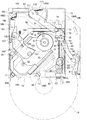
図1は本実施例によるディスク装置のベース本体の平面図、図2は同ディスク装置の要部平面図、図3は同ディスク装置の蓋体の平面図、図4は同ディスク装置のシャーシ外装のフロント面に装着されるベゼルの正面図である。
本実施例によるディスク装置は、ベース本体と蓋体とからシャーシ外装が構成され、このシャーシ外装のフロント面にベゼルが装着される。また本実施例によるディスク装置は、図3に示すベゼルに設けたディスク挿入口からディスクを直接挿入するスロットイン方式のディスク装置である。
図1に示すように、ディスクへの記録再生機能やディスクのローディング機能を行う各部品は、ベース本体10に装着される。
ベース本体10は、蓋体に対する深底部10Aと浅底部10Bが形成され、浅底部10Bによってフロント面からリア面に至るウイング部が形成されている。
ベース本体10のフロント側にはディスクを直接挿入するディスク挿入口11を形成し、ベース本体10のリア面の端部にはコネクタ12を配設している。ベース本体10のディスク挿入口11側にはトラバース30が配置され、ベース本体10のコネクタ12側にはリアベース13が配置されている。トラバース30とリアベース13とは互いが重ならないように配置されている。リアベース13のベース本体10面側にはプリント基板14が設けられている。
A disk device according to an embodiment of the present invention will be described below.
FIG. 1 is a plan view of a base body of a disk device according to the present embodiment, FIG. 2 is a plan view of a main part of the disk device, FIG. 3 is a plan view of a lid of the disk device, and FIG. It is a front view of the bezel with which a front surface is mounted | worn.
In the disk apparatus according to the present embodiment, a chassis exterior is constituted by a base body and a lid, and a bezel is attached to the front surface of the chassis exterior. The disk device according to the present embodiment is a slot-in type disk device in which a disk is directly inserted from a disk insertion opening provided in the bezel shown in FIG.
As shown in FIG. 1, each component that performs a disc recording / reproducing function and a disc loading function is mounted on a
The
A
トラバース30は、スピンドルモータ31とピックアップ32とピックアップ32を移動させる駆動手段33とを保持している。スピンドルモータ31はトラバース30の一端側に設けられ、ピックアップ32はトラバース30の一端側から他端側までを移動可能に設けられている。またピックアップ32は停止時にはトラバース30の他端側に配置される。
駆動手段33は、駆動モータと、ピックアップ32を摺動させる一対のレールと、駆動モータの駆動をピックアップ32に伝達する歯車機構とを有し、一対のレールはトラバース30の一端側と他端側とを連接するように両側部に配置されている。駆動モータはディスク挿入口11側のレールの外方に、駆動軸がレールと平行になるように配置されている。歯車機構は、この駆動モータとディスク挿入口11側のレールとの間の空間に配置されている。
The
The drive means 33 has a drive motor, a pair of rails for sliding the
トラバース30は、スピンドルモータ31がベース本体10の中央部に位置し、またピックアップ32の往復動範囲がスピンドルモータ31よりもディスク挿入口11側に位置し、またピックアップ32の往復移動方向がディスクの挿入方向と異なるように配設されている。ここで、ピックアップ32の往復移動方向とディスクの挿入方向とは、40度から45度の範囲の角度としている。
トラバース30は、一対のインシュレータ34A、34Bによってベース本体10に支持されている。
一対のインシュレータ34A、34Bは、スピンドルモータ31の位置よりもピックアップ32の静止位置側に配設し、ピックアップ32の静止位置よりもディスク挿入口11側の位置に配設することが好ましい。本実施例では、インシュレータ34Aはディスク挿入口11の内側近傍の一端側に、インシュレータ34Bはディスク挿入口11の内側近傍の中央部に設けている。インシュレータ34A、34Bは、弾性材料からなるダンパー機構を備えている。インシュレータ34A、34Bは、このダンパー機構によって、トラバース30がベース本体10から離間する方向に変位することができる。
In the
The
The pair of insulators 34 </ b> A and 34 </ b> B is preferably disposed closer to the stationary position of the
トラバース30のベース本体10側の面にはリブ35を設けている。このリブ35は、ディスク挿入口11と反対のレールの外方であって、ピックアップ32の静止位置側に設けている。またこのリブ35は、トラバース30をベース本体10側に近接させた時に、ベース本体10に当接することで、インシュレータ34A、34Bの位置でトラバース30をベース本体10から離間する方向に変位させるに十分な高さを有している。なお、本実施例では、リブ35をトラバース30のベース本体10側の面に設けた場合で説明したが、ベース本体10のトラバース30側の面に設けてもよい。またトラバース30のベース本体10側の面と、ベース本体10のトラバース30側の面の双方に設けてもよい。また本実施例ではトラバース30のベース本体10側への近接動作を利用して、インシュレータ34A、34B側のトラバース30を上昇させる構成としたが、インシュレータ34A、34Bの位置でのトラバース30の高さを変更する他の手段、例えばインシュレータ34A、34Bの高さを変更する手段によって実現することもできる。
なお、トラバース30は、インシュレータ34A、34Bを支点として、スピンドルモータ31をベース本体10と近接離間させるように動作する。
The
以下に、このトラバース30を動作させるカム機構を備えたメインスライダー40とサブスライダー50について説明する。
トラバース30を変位させるカム機構は、メインスライダー40とサブスライダー50にそれぞれ設けている。ここで、メインスライダー40とサブスライダー50とは、スピンドルモータ31の側方に位置するように配設されている。メインスライダー40は、その一端がシャーシ本体10のフロント面側、その他端がシャーシ本体10のリア面側となる方向に配設されている。また、サブスライダー50は、トラバース30とリアベース13との間に、メインスライダー40と直交する方向に配設されている。
トラバース30を変位させるカム機構は、第1のカム機構41と第2のカム機構51によって構成される。第1のカム機構41は、メインスライダー40のスピンドルモータ31側の面に、第2のカム機構51は、サブスライダー50のスピンドルモータ31側の面にそれぞれ設けられている。
なお、メインスライダー40とトラバース30との間にはベース部材15が設けられ、サブスライダー50とトラバース30との間にはベース部材16が設けられている。ここでベース部材15とベース部材16はベース本体10に固定され、ベース部材15に設けた縦溝によってトラバース30のカムピン36を位置規制し、ベース部材16に設けた縦溝によってトラバース30のカムピン37を位置規制している。
ここで、ベース部材16とサブスライダー50とは、第3のカム機構(図1では図示せず)によって連結している。そしてこの第3のカム機構は、第2のカム機構51によってトラバース30をベース本体10に対して離間する方向に移動させる時に、サブスライダー50をベース本体10に対して離間する方向に移動させる機能を備えている。
Below, the
Cam mechanisms for displacing the
A cam mechanism for displacing the
A
Here, the
メインスライダー40の一端側にはローディングモータ60が配設されている。ローディングモータ60とメインスライダー40の一端側とは歯車機構を介して連結されている。
図2に、ローディングモータ60近傍の平面図を示す。
ローディングモータ60の駆動軸61にはギア63が設けられ、これにかみ合うウオームギア群62が設けられており、本発明のギア群を構成している。そして、このウオームギア群62とかみ合うギア63には、その先端に傘歯車63aを形成している。なお、図4に示すように、シャーシ外装のフロント面またはベゼル140には、棒状体200を挿入可能な開口部142を設けている。
そして図2に示すように、棒状体200を開口部142から挿入することで、板ばね202aを変形させ、臨時歯車202を傘歯車63aに噛み合わせることができるように構成されている。そして、臨時歯車202を傘歯車63aに噛み合わせた状態で、棒状体200を回動させることで、ギア63及びウオームギア群62を回転させることができる。
なお、ローディングモータ60は、その本体がディスク挿入口11の中央部に、駆動軸61がディスク挿入口11の端部側に、それぞれが位置するように配設されている。
A loading
FIG. 2 shows a plan view of the vicinity of the
The
As shown in FIG. 2, the rod-shaped
The loading
このローディングモータ60の駆動によってメインスライダー40を長手方向に摺動させることができる。またメインスライダー40は、カムレバー70によってサブスライダー50と連結している。
カムレバー70は回動支点71を有し、ピン72及びピン73でメインスライダー40の上面に設けたカム溝と係合し、ピン74でサブスライダー50の上面に設けたカム溝と係合している。
このカムレバー70は、メインスライダー40の第1のカム機構41によってトラバース30を変位させるタイミングで、サブスライダー50を移動させ、サブスライダー50の移動によって第2のカム機構51を動作させてトラバース30を変位させる機能を有する。
The
The
The
以上説明した、コネクタ12、トラバース30、リアベース13、プリント基板14、インシュレータ34A、34B、メインスライダー40、サブスライダー50、ベース部材15、ベース部材16、及びローディングモータ60は、ベース本体10の深底部10Aに設けられ、これらの部材と蓋体との間に、ディスク挿入空間を形成する。
The
次に、ディスクを挿入するときにディスクを支持するガイド部材と、ディスクを挿入するときに動作するレバー部材について説明する。
深底部10Aのディスク挿入口11近傍の一端側には、所定長さの第1のディスクガイド17が設けられている。この第1のディスクガイド17は、ディスク挿入側から見た断面が、「コ」の字状の溝を有している。この溝によってディスクは支持される。
一方、ディスク挿入口11の他端側のベース本体10内には、引き込みレバー80が設けられ、この引き込みレバー80の可動側端部に第2のディスクガイド81を備えている。第2のディスクガイド81は、円筒状のローラで構成され、引き込みレバー80の可動側端部に回動自在に設けられている。また、第2のディスクガイド81のローラ外周には溝が形成され、この溝によってディスクは支持される。
引き込みレバー80は、可動側端部が固定側端部よりもディスク挿入口11側で動作するように配置され、固定側端部に回動支点82を有している。
また、引き込みレバー80の裏面(ベース本体10側の面)の可動側端部と固定側端部との間には長溝83が設けられている。一方、引き込みレバー80の表面の可動側端部と固定側端部との間には所定長さの第3のディスクガイド84が設けられている。
Next, a guide member that supports the disk when the disk is inserted and a lever member that operates when the disk is inserted will be described.
A
On the other hand, a pull-in
The pull-in
Further, a
引き込みレバー80は、サブレバー90によって動作する。
サブレバー90は、可動側の一端に凸部91を備え、他端側に回動支点92を備えている。サブレバー90の凸部91は、引き込みレバー80の長溝83内を摺動する。また、サブレバー90の回動支点92は、メインスライダー40上に位置している。なお、回動支点92は、メインスライダー40とは連動せず、ベース本体10にベース部材15を介して固定されている。またサブレバー90の回動支点92よりも凸部91側の下面には、ピン93を備えている。このピン93は、メインスライダー40の上面に設けられたカム溝内を摺動する。従って、サブレバー90は、メインスライダー40の移動にともなって角度が変更され、このサブレバー90の角度の変更によって引き込みレバー80の旋回角度を変更する。すなわち、サブレバー90の動作によって、引き込みレバー80の第2のディスクガイド81がスピンドルモータ31に近接離間するように動作する。なお、引き込みレバー80の可動側端部に近い側の長溝83の端部には、サブレバー90の旋回方向に延びる溝83Aが設けられている。この溝83Aによって、第2のディスクガイド81がディスクを最も引き込んだ時に、サブレバー90の旋回角度にばらつきが発生しても、引き込みレバー80の旋回角度にはばらつきが発生せず、ディスク引き込み量を安定させることができる。
The pull-in
The
ベース本体10の引き込みレバー80と異なる側部には、排出レバー100が設けられている。この排出レバー100の一端側の可動側端部には、ガイド101が設けられている。また、排出レバー100の他端側には、回動支点102が設けられている。また、排出レバー100の可動側端部には、ガイド101よりもリア面側に当接部103が設けられている。また、排出レバー100には、弾性体104が設けられている。この弾性体104の一端は排出レバー100に固定されており、他端はリアベース13に固定されている。当接部103は、弾性体104によってリア面側に引き込まれた場合に、リアベース13の当接部13Aと当接する。また排出レバー100は、弾性体104の弾性力によってディスク挿入口11側に引き出される。なお、排出レバー100は、リンクアーム105と排出スライダー106を介してメインスライダー40の動きと連動して動作する。ここでリンクアーム105は、軸105Aによってリアベース13に回動自在に設けられ、その一端側をピン105Bを介してメインスライダー40と連接し、その他端側をピン105Cによって排出スライダー106と連接している。排出レバー100はカムピン107によって排出スライダー106のカム溝と係合している。
A
ベース本体10のリア面側には規制レバー110が設けられている。この規制レバー110はリア面側端部を回動支点111とし、可動側端部にガイド112を備えている。この規制レバー110は、弾性体113によってガイド112側が常にフロント側に突出するように付勢されている。また、この規制レバー110は所定位置でリミットスイッチを動作させる。すなわち、ディスクが所定位置まで挿入されると、リミットスイッチがオフし、ローディングモータ60を駆動する。このローディングモータ60の駆動によって、メインスライダー40が摺動する。
また、排出レバー100と同じ側のベース本体10の側部には、ガイドレバー180が設けられている。ガイドレバー180は、リア面側を回動支点181とし、可動側にガイド182を備えている。このガイドレバー180は、弾性体183によってガイド182側がディスク側に突出するように付勢されている。また、このガイドレバー180は、リンクアーム105と排出スライダー106を介してメインスライダー40と連動し、このメインスライダー40の動きに応じて、ガイド182側がディスクから離間するように動作する。
なお、ディスク挿入口11の内側には、プロテクト機構120が設けられている。このプロテクト機構120は、ディスクがシャーシ外装内に既に装着された状態の時に、ディスク挿入口11からの他のディスクの挿入を阻止する。またスピンドルモータ31の近傍のトラバース30には開口部を備え、この開口部には、ベース本体10から蓋体に向かって突出したピン18を設けている。このピン18は、トラバース30が最もベース本体10側に移動した状態では、スピンドルモータ31のハブよりも蓋体側に突出する高さであり、またトラバース30がスピンドルモータ31の駆動状態(再生録音可能な作動状態)では、スピンドルモータ31のハブよりもベース本体10側に引き込んだ高さである。ピン18は、スピンドルモータ31に装着されるディスクの中心部の非記録面に対応する位置であって、スピンドルモータ31よりもインシュレータ34から離れた位置に設けることが好ましい。
A
A
A protect mechanism 120 is provided inside the
次に、図3を用いて同ディスク装置の蓋体について説明する。
蓋体130の外縁部には、複数のビス孔131が設けられ、蓋体130は、ビスによってベース本体10に取り付けられる。
蓋体130の中央部には、開口部132が設けられている。この開口部132は、ディスクの中心孔よりも大きな半径の円形開口である。従って、ディスクの中心孔に嵌合するスピンドルモータ31のハブよりも大きな開口である。
開口部132の外周部には、ベース本体10側に突出させた絞り部133が形成されている。また開口部132には、絞り部133からディスク挿入口11側に向かって先細り形状をした絞り部134が設けられている。この絞り部134によって、ベース本体10側に凸状ガイドを形成する。
Next, the lid of the disk device will be described with reference to FIG.
A plurality of screw holes 131 are provided in the outer edge portion of the
An
On the outer peripheral portion of the
次に図4を用いてベゼルについて説明する。
ベゼル140には挿入口141が設けられ、この挿入口141は中央部が最も幅が広く、両端部にいくに従って幅が狭くなるように形成されている。また、臨時歯車202に対向する位置のベゼル140には、開口部142を形成している。
Next, the bezel will be described with reference to FIG.
The
以下に、図5から図11を用いてディスクの挿入時における各部材の動きについて説明する。
図5はディスク挿入時の初期段階を示すディスク装置のベース本体の平面図であり、図3に示すディスク1Aの状態である。
なお、ディスク1が挿入されていない状態での引き込みレバー80は、スピンドルモータ31側に所定角度回動した状態で待機している。この状態では、サブレバー90の凸部91は、溝83Aまで至らない長溝83の可動側端部に位置する。また、ガイド17と第2のディスクガイド81との間隔は、ディスク1の直径より狭くなっている。
ディスク1挿入時の初期段階においては、ディスク1Aは、まずガイド17と第2のディスクガイド81とに当接し、ガイド17と第2のディスクガイド81によって支持されて位置規制される。
ディスク1Aを更に押し込むと、この挿入動作にともなって第2のディスクガイド81は、スピンドルモータ31から離れる方向に旋回動作する。この第2のディスクガイド81の旋回動作にともない、サブレバー90の凸部91は長溝83内を固定側端部に向かって摺動する。従ってサブレバー90も回動支点を中心に旋回動作する。ディスク1Aの挿入動作を更に続けると、ディスク1Aは排出レバー100のガイド101に当接する。図5はこの状態を図示している。
なお図5に示す状態では、ローディングモータ60は動作せず、従って、メインスライダー40やサブレバー50も動作しない。
Hereinafter, the movement of each member at the time of inserting the disc will be described with reference to FIGS.
FIG. 5 is a plan view of the base body of the disk device showing an initial stage when the disk is inserted, and shows the state of the
The pull-in
In the initial stage when the disc 1 is inserted, the
When the
In the state shown in FIG. 5, the loading
図6はディスク挿入途中段階を示すディスク装置のベース本体の平面図であり、図3に示すディスク1Bの状態である。
図5に示す状態から更にディスク1を挿入すると、ディスクの一端側はガイド17に支持された状態で、他端側は第3のディスクガイド84に支持される。引き込みレバー80はスピンドルモータ31から最も離間した状態となる。この状態では、サブレバー90の凸部91は、長溝83の固定側端部に位置する。また、ガイド17と第2のディスクガイド81との間隔は、ディスク1の直径とほぼ同じ寸法となっている。一方、排出レバー100は、ディスク1Bによってガイド101が押されるため、ディスクの挿入動作とともに回動を続ける。
図6の状態から更にディスク1Bを押し込むと、この挿入動作にともなって第2のディスクガイド81は、今度はスピンドルモータ31に近接する方向に移動する。この第2のディスクガイド81の旋回動作にともない、サブレバー90の凸部91は長溝83内を固定側端部から可動側端部に向かって摺動する。従ってサブレバー90も回動支点92を中心に旋回動作する。
一方、上記の動作過程において、ディスク1Bは規制レバー110のガイド112に当接し、規制レバー110が回動動作を行う。
第2のディスクガイド81がスピンドルモータ31に近接する方向に所定角度回動した時、ディスク1Bによって規制レバー110も所定角度回動する。そして、規制レバー110が所定角度回動することで、リミットスイッチが動作し、ローディングモータ60の駆動が開始される。なお、ガイドレバー180のガイド182はディスク1B側に突出した状態にあり、ディスク1Bは、このガイド182によっても支持されて摺動する。
このローディングモータ60の駆動によって、メインスライダー40はリア面側に摺動を開始する。そしてメインスライダー40の動作によって、サブレバー90のピン93が、対応するメインスライダー40に設けられたカム溝に沿って移動する。このとき、ピン93は、対応するカム溝によってスピンドルモータ31側に移動する。このピン93の移動によってサブレバー90は、引き込みレバー80をその可動側端部がスピンドルモータ31側に旋回移動する方向に付勢する。従って、引き込みレバー80はディスク1Bを挿入方向に付勢する。この引き込みレバー80の付勢力によって、ディスクは人為的な操作を離れ更に押し込まれる。
FIG. 6 is a plan view of the base body of the disk device showing a stage in the middle of inserting the disk, and shows the state of the
When the disc 1 is further inserted from the state shown in FIG. 5, one end side of the disc is supported by the
When the
On the other hand, in the above-described operation process, the
When the
By driving the
図7はディスク挿入完了段階を示すディスク装置のベース本体の平面図であり、図3に示すディスク1Cの状態である。
ディスク1Cは、第2のディスクガイド81、ガイドレバー180のガイド182、及び規制レバー110のガイド112の3点で支持され、ディスク1Cの中心孔がスピンドルモータ31と対応する位置に規制される。
一方、ローディングモータ60は駆動し続け、メインスライダー40も摺動動作を継続している。
FIG. 7 is a plan view of the base body of the disk device showing the disk insertion completion stage, which is the state of the
The disk 1 </ b> C is supported at three points: the
On the other hand, the loading
図7に示す状態から所定時間、メインスライダー40は移動するが、サブレバー90のピン93に対応するカム溝が移動方向と平行に形成されているため、サブレバー90は動作しない。この状態では、サブレバー90の凸部91は溝83Aに位置している。なお、引き込みレバー80も動作せず、ディスク1Cを支持した状態を継続している。
一方、カムレバー70についても、図7に示す状態からの所定時間は、依然として動作しない。すなわちカムレバー70のピン72、73に対応するカム溝が、メインスライダー40の移動方向と平行に形成されている。
図8は、図7に示す状態から、上記所定時間経過した段階を示すディスク装置のベース本体の平面図である。
図8に示す状態から、トラバース30の動作が開始する。すなわちトラバース30は、スピンドルモータ31側が蓋体130に近接する方向に動作を開始する。
Although the
On the other hand, the
FIG. 8 is a plan view of the base body of the disk device showing the stage after the predetermined time has elapsed from the state shown in FIG.
The operation of the
このトラバース30の動作メカニズムについて、図9から図11を用いて説明する。
図9は、トラバース30を、スピンドルモータ31側が蓋体130に最も近接する方向に動作させた状態を示すディスク装置のベース本体の平面図である。
図8の状態から、更にローディングモータ60を駆動し、メインスライダー40を移動すると、カムレバー70は、ピン72によって回動支点71を中心として回動する。このカムレバー70の回動によって、サブスライダー50は、メインスライダー40から離間する方向に摺動する。
このように、図8の状態からのメインスライダー40とサブスライダー50の摺動動作によってトラバース30が動作する。なお、引き込みレバー80は、ディスク1Cの保持を継続する。
The operation mechanism of the
FIG. 9 is a plan view of the base body of the disk device showing a state in which the
When the
Thus, the
図10は第1のカム機構を示すメインスライダーの側面図、図11は第2のカム機構と第3のカム機構を示すサブスライダーの側面図である。
図10に示すように、メインスライダー40には第1のカム機構41を構成する長溝が設けられており、この長溝にトラバース30に固定されたカムピン36が摺動自在に設けられている。ここで第1のカム機構41は、長溝とカムピン36によって構成されている。
一方、図11に示すように、サブスライダー50には第2のカム機構51を構成する長溝が設けられており、この長溝にトラバース30に固定されたカムピン37が摺動自在に設けられている。ここで第2のカム機構51は、長溝とカムピン37によって構成されている。また、サブスライダー50の両端には第3のカム機構52を構成する2つの同一形状からなる長溝が設けられており、これらの長溝にベース部材16に固定されたカムピン53が摺動自在に設けられている。ここで第3のカム機構52は、長溝とカムピン53によって構成されている。
FIG. 10 is a side view of the main slider showing the first cam mechanism, and FIG. 11 is a side view of the sub-slider showing the second cam mechanism and the third cam mechanism.
As shown in FIG. 10, the
On the other hand, as shown in FIG. 11, the sub-slider 50 is provided with a long groove constituting the
図10におけるカムピン36A、図11におけるカムピン37A及びカムピン53Aは、トラバース30が動作する前の図8の状態を示している。
また、図10におけるカムピン36B、図11におけるカムピン37B及びカムピン53Bは、トラバース30を、スピンドルモータ31側が蓋体130に最も近接する方向に動作させた状態である図9の状態を示している。
なお、図10、図11に示す矢印は、それぞれメインスライダー40とサブスライダー50の移動方向を示している。
図10に示すように、カムピン36は、カムピン36Aの位置からカムピン36Bの位置に移動することによってトラバース30を動作させる。従って、トラバース30のカムピン36の位置では、トラバース30をベース本体10に対して、カムピン36Aの位置からカムピン36Bの位置までのY軸方向移動距離だけ移動する。
一方、図11に示すように、カムピン37は、カムピン37Aの位置からカムピン37Bの位置に移動することによって、サブスライダー50に対してトラバース30を動作させる。従って、トラバース30のカムピン36の位置では、トラバース30をサブスライダー50に対して、カムピン36Aの位置からカムピン36Bの位置までのY軸方向移動距離だけ移動する。また、カムピン53は、カムピン53Aの位置からカムピン53Bの位置に移動することによって、ベース本体10に対してサブスライダー50を動作させる。従って、トラバース30のカムピン36の位置では、サブスライダー50をベース本体10に対して、カムピン53Aの位置からカムピン53Bの位置までのY軸方向移動距離だけ移動する。このように、サブスライダー50側では、トラバース30は、カムピン36Aの位置からカムピン36Bの位置までのY軸方向移動距離と、カムピン53Aの位置からカムピン53Bの位置までのY軸方向移動距離とを合わせた移動距離だけ、ベース本体10に対してY軸方向に移動する。
本実施例では、図10に示すカムピン36Aの位置からカムピン36Bの位置までのY軸方向移動距離は、図11に示すカムピン37Aの位置からカムピン37Bの位置までのY軸方向移動距離と、カムピン53Aの位置からカムピン53Bの位置までのY軸方向移動距離とを合わせた移動距離と同じとしている。
A
Further, the
The arrows shown in FIGS. 10 and 11 indicate the moving directions of the
As shown in FIG. 10, the
On the other hand, as shown in FIG. 11, the
In this embodiment, the Y-axis direction moving distance from the position of the
以上のように動作させ、トラバース30を、スピンドルモータ31側が蓋体130に最も近接する方向に動作させた状態では、ディスク1は、蓋体130に当接し、スピンドルモータ31と蓋体130とによって押圧される。この押圧力によってディスク1の中心孔にスピンドルモータ31のハブが嵌合し、チャッキングが完了する。
チャッキングが完了すると、トラバース30は、スピンドルモータ31側が蓋体130から離間する方向に動作する。
この動作は、更にローディングモータ60を駆動し、メインスライダー40を移動することによって行われる。
チャッキング完了からスピンドルモータ31が再生録音可能な作動状態(駆動状態)までの動作は、メインスライダー40では、カムピン36がカムピン36Bの位置からカムピン36Cの位置に移動することにより、サブスライダー50では、カムピン37がカムピン37Bの位置からカムピン37Cの位置に移動することにより、またカムピン53がカムピン53Bの位置からカムピン53Cの位置に移動することにより行われる。
そして、スピンドルモータ31が再生録音可能な作動状態(駆動状態)にある時には、ディスク1は、引き込みレバー80の第2のディスクガイド81、規制レバーのガイド101、及びガイドレバー180のガイド182からの支持が解除され、スピンドルモータ31のハブによってのみ保持された状態にある。ここで、引き込みレバー80の第2のディスクガイド81、規制レバーのガイド101、及びガイドレバー180のガイド182は、メインスライダー40の移動動作によって作動する。
When the
When the chucking is completed, the
This operation is further performed by driving the
The operation from the completion of chucking to the operation state (drive state) in which the
When the
ここで図11に示すように、サブスライダー50の第2のカム機構51には、例えば板ばねからなる弾性体55が、第3のカム機構52にも、例えば板ばねからなる弾性体56が設けられている。ここで弾性体55と弾性体56とは、弾性体55のカムピン37に対する付勢方向と、弾性体56のカムピン53に対する付勢方向とが異なるように設けている。なお、弾性体55と弾性体56との付勢方向は逆方向であることが好ましい。
また、装着されたディスク1を排出する時には、ローディングモータ60を駆動し、メインスライダー40を移動することにより行われ、基本的には上記の動作が逆に行われる。
As shown in FIG. 11, the
Further, when the loaded disc 1 is ejected, the loading
以下に、装着されているディスクが排出されるまでを簡単に説明する。
まず、エジェクト指示に基づき、ローディングモータ60が駆動され、メインスライダー40がディスク挿入口11側に移動する。
従って、メインスライダー40では、カムピン36がカムピン36Cの位置からカムピン36Bの位置を経由してカムピン36Aの位置に移動し、サブスライダー50では、カムピン37がカムピン37Cの位置からカムピン37Bの位置を経由してカムピン37Aの位置に移動し、またカムピン53がカムピン53Cの位置からカムピン53Bの位置を経由してカムピン53Aの位置に移動にする。
上記のように、それぞれのカム機構が動作することにより、ディスク1は、一旦蓋体130側に移動した後に、ベース本体10側に移動する。
ディスク1は、ベース本体10側に移動する時に、ディスク1の外周側で、第2のディスクガイド81、ガイド181、112に当接し、ディスク1の内周側でピン18に当接する。従って、トラバース30のベース本体10側への移動にともなって、ディスク1には、第2のディスクガイド81、ガイド101、112及びピン18から蓋体130側への力が加わり、ディスク1はスピンドルモータ31のハブから解除される。なお、本実施例のように、ピン18をスピンドルモータ31の外周位置であって、スピンドルモータ31よりもインシュレータ34から離れた位置に設けることで、第2のディスクガイド81、ガイド181、112の作用が働かなくてもディスク1のスピンドルモータ31のハブからの解除を行うことができる。
その後、排出レバー100は、メインスライダー40の動作によってリンクアーム105と排出スライダー106が動作し、カムピン107のロックが解除され、弾性体104の弾性力により、可動側端部がディスク挿入口11側に回動する。従って、スピンドルモータ31のハブから外されたディスク1は、排出レバー100によってディスク挿入口11側に押し出される。なお、排出レバー100が動作する状態では、引き込みレバー80は、その可動側端部がスピンドルモータ31から最も離間する方向に移動した状態に保持されている。なお、引き込みレバー80の位置は、第2のディスクガイド81がディスク1に接触しない位置であればよい。このようにディスク排出時に、ディスク1が第2のディスクガイド81に当接しない位置に引き込みレバー80を配置することで、ディスク排出時のトラブルを防止することができる。
A brief description will be given below until the loaded disc is ejected.
First, the loading
Therefore, in the
As described above, when each cam mechanism operates, the disc 1 once moves to the
When the disk 1 moves to the
Thereafter, the
次に、ローディングモータ60によらないディスク排出動作について説明する。
図2に示すように、棒状体200を開口部142から挿入することで臨時歯車202をギア63に噛み合わせる。そして、棒状体200を回転させることで、ウオームギア群62を介して連結されているメインスライダー40を摺動させる。
このときのメインスライダー40の動作は、通常のエジェクト動作と同じである。従って、メインスライダー40はディスク挿入口11側に移動し、トラバース移動手段によってトラバース30を変位させ、トラバース30の変位によってディスクのスピンドルモータへの保持を解除し、その後排出レバー100が動作する。
すなわち、まず、棒状体200の回転操作によって、メインスライダー40がディスク挿入口11側に移動する。メインスライダー40では、カムピン36がカムピン36Cの位置からカムピン36Bの位置を経由してカムピン36Aの位置に移動し、サブスライダー50では、カムピン37がカムピン37Cの位置からカムピン37Bの位置を経由してカムピン37Aの位置に移動し、またカムピン53がカムピン53Cの位置からカムピン53Bの位置を経由してカムピン53Aの位置に移動にする。それぞれのカム機構が動作することにより、ディスク1は、一旦蓋体130側に移動した後に、ベース本体10側に移動する。
ディスク1は、ベース本体10側に移動する時に、ディスク1の外周側で、第2のディスクガイド81、ガイド181、112に当接し、ディスク1の内周側でピン18に当接する。従って、トラバース30のベース本体10側への移動にともなって、ディスク1には、第2のディスクガイド81、ガイド101、112及びピン18から蓋体130側への力が加わり、ディスク1はスピンドルモータ31のハブから解除される。なお、本実施例のように、ピン18をスピンドルモータ31の外周位置であって、スピンドルモータ31よりもインシュレータ34から離れた位置に設けることで、第2のディスクガイド81、ガイド181、112の作用が働かなくてもディスク1をスピンドルモータ31のハブから解除することができる。
その後、排出レバー100は、メインスライダー40の動作によってリンクアーム105と排出スライダー106が動作し、カムピン107のロックが解除され、弾性体104の弾性力により、可動側端部がディスク挿入口11側に回動する。従って、スピンドルモータ31のハブから外されたディスク1は、排出レバー100によってディスク挿入口11側に押し出される。なお、排出レバー100が動作する状態では、引き込みレバー80は、その可動側端部がスピンドルモータ31から最も離間する方向に移動した状態に保持されている。
Next, the disc ejecting operation not using the
As shown in FIG. 2, the
The operation of the
That is, first, the
When the disk 1 moves to the
Thereafter, the
以下本発明の他の実施例によるディスク装置について説明する。
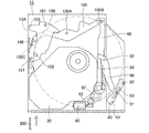
図12は本発明の他の実施例によるディスク装置のシャーシ外装のフロント面の正面図、図13から図15は同実施例によるディスク装置のベース本体のそれぞれ別の状態における要部平面図である。
なお、本実施例のディスク装置においては、第1の実施例と同一の構成については、同一の番号を付し、説明を省略する。
A disk device according to another embodiment of the present invention will be described below.
FIG. 12 is a front view of a front surface of a chassis exterior of a disk device according to another embodiment of the present invention, and FIGS. 13 to 15 are plan views of main parts in different states of the base body of the disk device according to the embodiment. .
In the disk device of the present embodiment, the same components as those in the first embodiment are denoted by the same reference numerals and description thereof is omitted.
本ディスク装置では、図12に示すように、シャーシ外装のフロント面のベゼル140には、棒状体200を挿入可能な開口部143を設けており、棒状体200をこの開口部143から挿入することで、排出スライダー106が移動する構成としている。すなわち、棒状体200の開口部143からの操作方向と、排出スライダー106の排出動作時の操作方向とを一致させている。
以下に、ローディングモータ60の非駆動時における排出レバー100によるディスクの排出動作について説明する。
棒状体200により、排出スライダー106が矢印W方向に移動すると、これに連結されたリンクアーム105が図14の矢印X方向に回転移動し、これにピン105Bで連結されているスライダー40が長手方向矢印Y方向に摺動し、スライダー40に設けた前述のカム機構によってトラバース30が移動する。そして図15に示すように、排出レバー100は、排出スライダー106の動作によって、カムピン107が動かされ、次に、弾性体104のばね弾性により、排出レバー100が矢印Z方向に回動する。排出レバー100が矢印Z方向に回動するのに従い、第1の実施例に示すように排出動作がおこなわれることによって、ローディングモータ60の非駆動時にも排出レバー100によるディスクの排出が可能となる。
このように、この実施例では、棒状体200による開口部143からの操作で、排出レバー100をローディングモータ60の非駆動時に動作させる排出駆動機構が構成される。
すなわち、本実施例における排出駆動機構は、フロント面に設けた棒状体200を挿入可能な開口部143に対向する位置に排出スライダー106を配置し、棒状体200の開口部143からの操作方向Wと、排出スライダー106の排出動作時の操作方向とを一致させている。なお、棒状体200の操作によっても排出スライダー106が摺動可能となるように、必要に応じてギア63とウオームギア群62との交差角を調整し、ギア63とウオームギア群62とは、逆転できるねじれ角に設定している。以上の構成によって、棒状体200による操作でも、排出レバー106を動作させることを可能な構成とした。
これによって、ローディングモータ60が異常停止した場合であっても、排出駆動機構を使ってディスクを取り出せ、トラブル対処を容易にできる。
In the present disk device, as shown in FIG. 12, the
Hereinafter, a disk discharge operation by the
When the
Thus, in this embodiment, a discharge drive mechanism that operates the
That is, the discharge drive mechanism in the present embodiment arranges the
As a result, even when the
次に本発明の他の実施例によるディスク装置について説明する。
図16は同ディスク装置の要部平面図である。なお、本実施例は図16に示す以外の構成は実施例1と同じであるため、実施例1と同じ構成と動作については説明を省略する。
ローディングモータ60の駆動軸61にはギア63が設けられ、これにかみ合うウオームギア群62が設けられている。そして、このウオームギア群62とかみ合うギア63には、その先端に傘歯車63aを形成している。なお、シャーシ外装のフロント面またはベゼル140には、棒状体200を挿入可能な開口部142を設けている。
そして本実施例においては、あらかじめ臨時歯車202が傘歯車63aに噛み合わされて構成されている。そして、棒状体200を回動させることで、ギア63及びウオームギア群62を回転させることができる。
なお、ローディングモータ60は、その本体がディスク挿入口11の中央部に、駆動軸61がディスク挿入口11の端部側に、それぞれが位置するように配設されている。
Next, a disk device according to another embodiment of the present invention will be described.
FIG. 16 is a plan view of the main part of the disk device. The configuration of the present embodiment is the same as that of the first embodiment except for the configuration shown in FIG.
A
In this embodiment, the
The loading
次に本発明の他の実施例によるディスク装置について説明する。
図17は本発明の他の実施例によるディスク装置のベース本体の要部平面図、図18は同実施例によるディスク装置のベース本体の別の状態における要部平面図である。
なお、本実施例のディスク装置においては、上記実施例と同一の構成については、同一の番号を付し、説明を省略する。
本ディスク装置においても、シャーシ外装のフロント面のベゼル140には、棒状体200を挿入可能な開口部142を設けている。そして、開口部142に対向する位置に臨時スライダー45を配置し、臨時スライダー45をウオームギア群62と係合させ、臨時スライダー45の摺動によってスライダー40が摺動する構成としている。なお、棒状体200の開口部142からの操作方向と、臨時スライダー45の操作方向とを一致させている。
以下に、ローディングモータ60の非駆動時における排出レバー100によるディスクの排出動作について説明する。
棒状体200により、臨時スライダー45が移動すると、これに係合されたウオームギア群62が図18の矢印A方向に回転し、スライダー40が長手方向矢印Y方向に摺動し、スライダー40に設けた前述のカム機構によってトラバース30が移動する。そして、スライダー40の長手方向矢印Y方向への摺動によって、これに連結されたリンクアーム105が矢印X方向に回転移動し、排出スライダー106が矢印W方向に移動する。排出レバー100は、排出スライダー106の矢印W方向への動作によって、カムピン107が動かされ、次に、弾性体104のばね弾性により、排出レバー100が矢印Z方向に回動する。排出レバー100が矢印Z方向に回動するのに従い、上記実施例と同様に排出動作が行われることによって、ローディングモータ60の非駆動時にも排出レバー100によるディスクの排出が可能となる。
このように、この実施例では、棒状体200による開口部142からの操作で、排出レバー100をローディングモータ60の非駆動時に動作させる排出駆動機構が構成される。
すなわち、本実施例における排出駆動機構は、フロント面に設けた棒状体200を挿入可能な開口部142に対向する位置に臨時スライダー45を配置し、棒状体200の開口部142からの操作方向と、臨時スライダー45の排出動作時の操作方向とを一致させている。
Next, a disk device according to another embodiment of the present invention will be described.
FIG. 17 is a plan view of a main part of a base body of a disk apparatus according to another embodiment of the present invention, and FIG.
In the disk device of this embodiment, the same components as those in the above embodiment are given the same reference numerals, and the description thereof is omitted.
Also in this disk apparatus, the
Hereinafter, a disk discharge operation by the
When the
As described above, in this embodiment, a discharge drive mechanism that operates the
That is, the discharge drive mechanism in the present embodiment has the
以上のように本実施例によれば、臨時スライダー45によってスライダー40を動作させることができ、臨時スライダー45を押し込む操作で排出レバー100を動作させることができるので排出操作を容易に行うことができる。
なお、実施例2及び実施例4におけるディスク装置では、ローディングモータ60とスライダー40との連結を解除する連結解除手段を有することが好ましい。この連結解除手段については、特に図示はしないが、ローディングモータ60を傾かせ、又はローディングモータ60をウオームギア群62から離間する方向に退避させることで、ギア63とウオームギア群62との連結を解除するものである。このように連結解除手段を設けることで、棒状体200の操作に先立ってローディングモータ60とスライダー40との連結を解除することができ、排出操作を容易に行うことができる。
As described above, according to the present embodiment, the
In the disk devices in the second and fourth embodiments, it is preferable to have a connection release means for releasing the connection between the loading
本発明によれば、プリント基板とトラバースの配置構成によって薄型化と小型化を実現しつつ、ローディングモータが異常停止した場合であっても、簡単な操作でディスクを取り出せ、トラブル対処を容易にできるので、表示手段と入力手段と演算処理手段などを一体化した、いわゆるノート型パソコン本体に内蔵、または一体的にセットされるディスク装置として有用である。 According to the present invention, it is possible to remove a disk with a simple operation and to easily deal with a trouble even when the loading motor stops abnormally while realizing a reduction in thickness and size by the arrangement configuration of the printed circuit board and the traverse. Therefore, the present invention is useful as a disk device that is built in or integrated with a so-called notebook personal computer main body in which display means, input means, arithmetic processing means, and the like are integrated.
10 ベース本体
11 ディスク挿入口
12 コネクタ
13 リアベース
14 プリント基板
15 ベース部材
16 ベース部材
17 ガイド
30 トラバース
31 スピンドルモータ
32 ピックアップ
40 メインスライダー
45 臨時スライダー
41 第1のカム機構
50 サブスライダー
51 第2のカム機構
52 第3のカム機構
60 ローディングモータ
70 カムレバー
80 引き込みレバー
81 第2のディスクガイド
83 長溝
90 サブレバー
100 排出レバー
130 蓋体
142 開口部
143 開口部
200 棒状体
DESCRIPTION OF
Claims (1)
前記トラバースに支持された前記スピンドルモータが前記ベース本体側と前記蓋体側との間で移動可能に前記トラバースを変位させるトラバース移動手段を設け、
前記トラバース移動手段は、シャーシ外装のフロント面近傍に設けたローディングモータと、このローディングモータの駆動軸とギア群を介して連結され、前記ローディングモータの駆動によって長手方向に摺動するメインスライダーと、前記メインスライダーに設けたカム機構によって構成し、
前記メインスライダーを、前記スピンドルモータの側方に、その一端が前記フロント面側、その他端が前記リア面側となる方向に配設し、
前記メインスライダーと同一方向を長手方向とする排出スライダーを、リンクアームを介して前記メインスライダーと連結し、
前記排出スライダーを、前記ベース本体の一端のリア面側に配置し、
前記ベース本体の一端のリア面側には、排出レバーを設け、
前記ベース本体の他端のフロント側には、引き込みレバーを設け、
前記排出レバーは、前記排出スライダーの移動にともなって回動動作し、
前記引き込みレバーは、前記メインスライダーの移動にともなって旋回動作し、
前記メインスライダーの動作によって前記引き込みレバーを前記ディスクに接触しない位置に回動させるディスク装置であって、
前記シャーシ外装のフロント面の一端に、棒状体を挿入可能な開口部を設け、
前記開口部に対向する位置に前記排出スライダーが配置され、
前記棒状体の前記開口部からの操作方向と、前記排出スライダーの排出動作時の操作方向とを一致させ、
前記棒状体の挿入によって、前記排出スライダーが移動することで前記リンクアームが回転移動するとともに前記メインスライダーが摺動し、前記メインスライダーに設けた前記カム機構によって前記トラバースが移動し、
前記排出レバーは、前記排出スライダーの動作によって回動して前記ディスクを排出することを特徴とするディスク装置。 A chassis exterior is constituted by a base body and a lid, a disk insertion slot for directly inserting a disk is formed on the front surface of the chassis exterior, and a connector is disposed on the rear surface of the chassis exterior, and the base body is traversed. And a printed circuit board, a spindle motor, a pickup, and a drive means for moving the pickup are held by the traverse, the traverse is disposed on the disk insertion port side, and the printed circuit board is disposed on the connector side, respectively.
A traverse moving means for displacing the traverse so that the spindle motor supported by the traverse is movable between the base body side and the lid side;
The traverse moving means includes a loading motor provided near the front surface of the chassis exterior, a main slider that is connected to the loading motor via a drive shaft and a gear group, and slides in the longitudinal direction by the driving of the loading motor; Consists of a cam mechanism provided on the main slider,
The main slider is disposed on the side of the spindle motor in such a direction that one end is on the front surface side and the other end is on the rear surface side.
A discharge slider whose longitudinal direction is the same direction as the main slider is connected to the main slider via a link arm,
The discharge slider is disposed on the rear surface side of one end of the base body,
On the rear surface side of one end of the base body, a discharge lever is provided,
A pull-in lever is provided on the front side of the other end of the base body,
The discharge lever rotates as the discharge slider moves,
The pull-in lever pivots as the main slider moves,
Wherein a disk device to rotate the front Symbol pull lever by the movement of the main slider to the position that does not contact the disk,
At one end of the front surface of the chassis exterior, an opening through which a rod-like body can be inserted is provided,
The discharge slider is disposed at a position facing the opening,
The operation direction from the opening of the rod-shaped body and the operation direction during the discharge operation of the discharge slider are matched,
By inserting the rod-shaped body, the discharge slider moves, the link arm rotates and the main slider slides, and the traverse is moved by the cam mechanism provided on the main slider,
The disc apparatus is characterized in that the eject lever is rotated by the operation of the eject slider to eject the disc.
Priority Applications (1)
| Application Number | Priority Date | Filing Date | Title |
|---|---|---|---|
| JP2004327832A JP4376756B2 (en) | 2004-04-14 | 2004-11-11 | Disk unit |
Applications Claiming Priority (2)
| Application Number | Priority Date | Filing Date | Title |
|---|---|---|---|
| JP2004118847 | 2004-04-14 | ||
| JP2004327832A JP4376756B2 (en) | 2004-04-14 | 2004-11-11 | Disk unit |
Publications (3)
| Publication Number | Publication Date |
|---|---|
| JP2005327431A JP2005327431A (en) | 2005-11-24 |
| JP2005327431A5 JP2005327431A5 (en) | 2006-02-23 |
| JP4376756B2 true JP4376756B2 (en) | 2009-12-02 |
Family
ID=35473639
Family Applications (1)
| Application Number | Title | Priority Date | Filing Date |
|---|---|---|---|
| JP2004327832A Active JP4376756B2 (en) | 2004-04-14 | 2004-11-11 | Disk unit |
Country Status (1)
| Country | Link |
|---|---|
| JP (1) | JP4376756B2 (en) |
Families Citing this family (8)
| Publication number | Priority date | Publication date | Assignee | Title |
|---|---|---|---|---|
| JP2007157189A (en) * | 2005-11-30 | 2007-06-21 | Sony Corp | Disk drive unit |
| JP4331163B2 (en) * | 2005-12-28 | 2009-09-16 | パナソニック株式会社 | Slot-in type disk unit |
| JP4322873B2 (en) | 2006-01-04 | 2009-09-02 | パナソニック株式会社 | Slot-in type disk unit |
| JP2007200377A (en) * | 2006-01-23 | 2007-08-09 | Matsushita Electric Ind Co Ltd | Slot-in type disk apparatus |
| JP4738187B2 (en) * | 2006-01-31 | 2011-08-03 | パナソニック株式会社 | Slot-in type disk unit |
| JP4331171B2 (en) * | 2006-02-03 | 2009-09-16 | パナソニック株式会社 | Slot-in type disk unit |
| KR100699748B1 (en) * | 2006-02-16 | 2007-03-28 | 도시바삼성스토리지테크놀러지코리아 주식회사 | Optical disc device including a release means |
| JP2008226360A (en) | 2007-03-13 | 2008-09-25 | Sony Nec Optiarc Inc | Disk drive device and electronic apparatus |
-
2004
- 2004-11-11 JP JP2004327832A patent/JP4376756B2/en active Active
Also Published As
| Publication number | Publication date |
|---|---|
| JP2005327431A (en) | 2005-11-24 |
Similar Documents
| Publication | Publication Date | Title |
|---|---|---|
| JP3522235B2 (en) | Disk unit | |
| JPWO2005101401A1 (en) | Disk unit | |
| WO2006025197A1 (en) | Disk device | |
| JP4376756B2 (en) | Disk unit | |
| JP4103742B2 (en) | Disk drive device | |
| JP4156397B2 (en) | Disk unit | |
| JP2005327431A5 (en) | ||
| JP2005085449A (en) | Disk drive device | |
| WO2005086154A1 (en) | Chucking device | |
| JP4103744B2 (en) | Disk drive device | |
| JP4322873B2 (en) | Slot-in type disk unit | |
| JP3822615B2 (en) | Disk unit | |
| JP4758239B2 (en) | Slot-in type disk unit | |
| JP4754778B2 (en) | Disk drive device | |
| JP4322868B2 (en) | Slot-in type disk unit | |
| JP3822605B2 (en) | Disk device chucking method and disk device | |
| JP4285164B2 (en) | Disk drive device | |
| JP4331171B2 (en) | Slot-in type disk unit | |
| JP4738187B2 (en) | Slot-in type disk unit | |
| JP4368764B2 (en) | Disk unit | |
| JP4103743B2 (en) | Disk drive device | |
| JP4331163B2 (en) | Slot-in type disk unit | |
| JP2007179690A5 (en) | ||
| JP2007207373A5 (en) | ||
| JP2005302187A (en) | Disk drive |
Legal Events
| Date | Code | Title | Description |
|---|---|---|---|
| A871 | Explanation of circumstances concerning accelerated examination |
Free format text: JAPANESE INTERMEDIATE CODE: A871 Effective date: 20050929 |
|
| A975 | Report on accelerated examination |
Free format text: JAPANESE INTERMEDIATE CODE: A971005 Effective date: 20051011 |
|
| A25B | Written notification of impossibility to examine because of no request for precedent application |
Free format text: JAPANESE INTERMEDIATE CODE: A2522 Effective date: 20051206 |
|
| A521 | Written amendment |
Free format text: JAPANESE INTERMEDIATE CODE: A523 Effective date: 20060105 |
|
| A131 | Notification of reasons for refusal |
Free format text: JAPANESE INTERMEDIATE CODE: A131 Effective date: 20060905 |
|
| A521 | Written amendment |
Free format text: JAPANESE INTERMEDIATE CODE: A523 Effective date: 20061102 |
|
| A02 | Decision of refusal |
Free format text: JAPANESE INTERMEDIATE CODE: A02 Effective date: 20061205 |
|
| A521 | Written amendment |
Free format text: JAPANESE INTERMEDIATE CODE: A523 Effective date: 20061227 |
|
| A911 | Transfer of reconsideration by examiner before appeal (zenchi) |
Free format text: JAPANESE INTERMEDIATE CODE: A911 Effective date: 20070205 |
|
| A912 | Removal of reconsideration by examiner before appeal (zenchi) |
Free format text: JAPANESE INTERMEDIATE CODE: A912 Effective date: 20070223 |
|
| A521 | Written amendment |
Free format text: JAPANESE INTERMEDIATE CODE: A523 Effective date: 20080117 |
|
| A521 | Written amendment |
Free format text: JAPANESE INTERMEDIATE CODE: A523 Effective date: 20090722 |
|
| A01 | Written decision to grant a patent or to grant a registration (utility model) |
Free format text: JAPANESE INTERMEDIATE CODE: A01 |
|
| A61 | First payment of annual fees (during grant procedure) |
Free format text: JAPANESE INTERMEDIATE CODE: A61 Effective date: 20090909 |
|
| R150 | Certificate of patent or registration of utility model |
Free format text: JAPANESE INTERMEDIATE CODE: R150 |
|
| FPAY | Renewal fee payment (event date is renewal date of database) |
Free format text: PAYMENT UNTIL: 20120918 Year of fee payment: 3 |