JP4376567B2 - Buffer member for external storage device - Google Patents
Buffer member for external storage device Download PDFInfo
- Publication number
- JP4376567B2 JP4376567B2 JP2003275962A JP2003275962A JP4376567B2 JP 4376567 B2 JP4376567 B2 JP 4376567B2 JP 2003275962 A JP2003275962 A JP 2003275962A JP 2003275962 A JP2003275962 A JP 2003275962A JP 4376567 B2 JP4376567 B2 JP 4376567B2
- Authority
- JP
- Japan
- Prior art keywords
- holding portion
- surface holding
- external storage
- storage device
- housing
- Prior art date
- Legal status (The legal status is an assumption and is not a legal conclusion. Google has not performed a legal analysis and makes no representation as to the accuracy of the status listed.)
- Expired - Lifetime
Links
Images


Description
本発明は、例えばノートブックタイプのパーソナルコンピュータのような情報処理装置に収容するハードディスク装置などの外部記憶装置を衝撃や振動から保護する緩衝部材に関する。 The present invention relates to a buffer member that protects an external storage device such as a hard disk device housed in an information processing device such as a notebook type personal computer from impact and vibration.
例えば図11で示すように、情報処理装置としてのノートブックタイプのパーソナルコンピュータ(以下、「ノートPC」と略記する。)1には、ディスク状記憶媒体を収容する外部記憶装置としてのハードディスク装置2が格納されている。このハードディスク装置2は、上面3aと底面3bを略長方形とした薄板状の筐体3を備えている。上面3aと底面3bには、矩形状とした弾性材でなるシート状緩衝部材4が、例えば両面テープなどで固定されている。そして、図12で模式的に示すように、ハードディスク装置2がノートPC1の格納部1aに格納されて蓋1bで閉塞されると、シート状緩衝部材4は、ハードディスク装置2と格納部1aとの隙間に挟み込まれた状態で配置され、振動や衝撃からハードディスク装置2を保護する機能を担うことになる。このシート状緩衝部材4に関する先行技術の例が、特願2002−379283号(特許文献1)明細書に記載されている。
ところで、このようなハードディスク装置2は、ノートPC1などに搭載されれば、自動車や電車の乗車中に使用される場合もある。そのため、静止環境下で使用される場合よりも、外部からの振動や衝撃からハードディスク装置2を守る必要性が高い。
By the way, if such a
しかしながら、ハードディスク装置2に内蔵された磁気ディスク2aと対向する上面3a、底面3bの中央寄りの部分に従来型のシート状緩衝部材4を取付けてしまうと、シート状緩衝部材4の押圧により、上面3aの裏面と磁気ディスク2aとの隙間が狭くなって、精緻な動作が要求される磁気ヘッド2bの動作に、悪影響を及ぼすおそれがある。また、中央寄りの部分ではなく端部に取付けたとしても、ハードディスク装置2が、上面3aや底面3bの広範囲で、シート状緩衝部材4を介して、格納部1aや蓋1bと接することとなるため、特に上下方向の振動が、広範囲で筐体3の上面3aや底面3bを通じて直接的にハードディスク装置2に伝わり、好ましいものではない。
However, if the conventional sheet-
また、シート状緩衝部材4は、その取付け作業においても、ハードディスク装置2の上面3a、底面3bの四隅に個別に両面テープで固定するため、作業性が悪く、固定の位置決めが困難という問題がある。そして、もし固定位置がずれると、当初予定している振動減衰特性が得られない場合もある。
Further, since the sheet-
一方、シート状緩衝部材4の取付方法として、図13で示すように、ハードディスク装置2の高さT1よりも幅広のシート状緩衝部材4を用いて、ハードディスク装置2の筐体3の長手側面3c側にこのシート状緩衝部材4を置き、長手側面3cの面端から上方および下方にシート状緩衝部材4を突出させた状態で、ネジ5を用いて筐体3に支持する方法もある。しかしながらこの方法では、ネジ5等で外部記憶装置に取付ける必要があり、取付作業に手間がかかるし、部品点数が多くなる点で不利である。また、ネジ5等を用いずに、シート状緩衝部材4を両面テープや接着剤等でハードディスク装置2に取付けるとすると、接着性が弱い点でやはり不利である。
On the other hand, as a method of attaching the sheet-
そこで、本発明は、ハードディスク装置などの外部記憶装置に用いられる緩衝部材であって、特に外部からの振動や衝撃が外部記憶装置に伝わりにくく、取付けが容易な緩衝部材を得ることを目的とする。 SUMMARY OF THE INVENTION The present invention provides a shock-absorbing member used in an external storage device such as a hard disk device, and more particularly, to obtain a shock-absorbing member that is difficult to transmit external vibration and shock to the external storage device and can be easily mounted. .
上記目的を達成すべく本発明は、筐体にディスク状記録媒体を収容する外部記憶装置と、この外部記憶装置を収容する情報処理装置の格納部と、の隙間に介在させる弾性材でなる緩衝部材について、外部記憶装置の筐体の側面を保持する側面保持部と、側面保持部から片持ち梁状に突出し該筐体の上面を保持する上面保持部と、側面保持部から片持ち梁状に突出し該筐体の底面を保持する底面保持部と、を有する保持部を備え、筐体の上面及び底面からの側面保持部の上下方向に沿う突出長さに対して、上面保持部と底面保持部の肉厚を薄肉に形成したことを特徴とする緩衝部材を提供する。 In order to achieve the above object, the present invention provides a buffer made of an elastic material interposed in a gap between an external storage device that houses a disk-shaped recording medium in a housing and a storage portion of an information processing device that houses the external storage device. Regarding the members, a side surface holding part that holds the side surface of the housing of the external storage device, a top surface holding part that protrudes from the side surface holding part in a cantilever shape, and holds the top surface of the housing, and a cantilever shape from the side surface holding part And a bottom surface holding portion that holds the bottom surface of the housing, and the upper surface holding portion and the bottom surface with respect to the protruding length along the vertical direction of the side surface holding portion from the top surface and the bottom surface of the housing. A shock-absorbing member characterized in that the thickness of the holding portion is formed thin.
本発明の緩衝部材によれば、側面保持部から片持ち梁状に突出する上面保持部と底面保持部によって、簡単な取付作業によって、確実に外部記憶装置を保持することができる。そして、これら上面保持部と底面保持部の肉厚は、筐体の上面及び底面から上下方向に沿って突出する側面保持部の突出長さよりも薄肉である。このため、側面保持部の上端と下端が格納部に対して当接し、外部記憶装置を弾性的に浮動支持することが可能であり、衝撃や振動を効果的に緩衝できる。 According to the shock-absorbing member of the present invention, the external storage device can be reliably held by a simple mounting operation by the upper surface holding portion and the bottom surface holding portion protruding in a cantilever shape from the side surface holding portion. And the thickness of these upper surface holding | maintenance parts and bottom face holding | maintenance parts is thinner than the protrusion length of the side surface holding | maintenance part which protrudes along an up-down direction from the upper surface and bottom face of a housing | casing. For this reason, the upper end and the lower end of the side surface holding portion abut against the storage portion, and the external storage device can be elastically supported in a floating manner, so that shock and vibration can be effectively buffered.
そして、この緩衝部材は、上面保持部と底面保持部を、筐体の上面と底面の面内方向に向けて徐々に薄肉に形成することができる。上面保持部と底面保持部を、筐体の上面と底面の面内方向に向けて徐々に薄肉にしたため、側面保持部に対する上面保持部と底面保持部の付け根側では、緩衝部材が厚肉で剛性が高くなる。このため、外部記憶装置の荷重を確実に支持することが可能で、衝撃を受けても緩衝部材から外部記憶装置が外れにくく安定的に保持できる。一方、上面保持部と底面保持部の先端(自由端)側では、付け根側よりも薄肉となるため、厚肉の場合と比較して緩衝部材の重量低減と、材料少量化を達成できる。さらに、上面保持部や底面保持部を格納部等と接触させずに外部記憶装置に対する保持面を広くしたため、振動減衰特性を変化させずに、外部記憶装置の保持力を高めることが可能である。 And this buffer member can form an upper surface holding | maintenance part and a bottom face holding | maintenance part gradually thinly toward the surface direction of the upper surface and bottom face of a housing | casing. Since the upper surface holding portion and the bottom surface holding portion are gradually thinned in the in-plane direction of the upper surface and the bottom surface of the housing, the buffer member is thick on the base side of the upper surface holding portion and the bottom surface holding portion with respect to the side surface holding portion. Increases rigidity. For this reason, it is possible to reliably support the load of the external storage device, and even when an impact is applied, the external storage device is not easily detached from the buffer member and can be stably held. On the other hand, the tip (free end) side of the upper surface holding portion and the bottom surface holding portion is thinner than the base side, so that it is possible to reduce the weight of the buffer member and reduce the amount of material compared to the case of the thick wall . Furthermore, because of the wide holding surface to the external storage device without them touch a storage unit such as the upper surface holding portion and the bottom holder, without changing the damping characteristics, can be improved retention of the outer portion storage device It is.
本発明はまた、上面保持部と底面保持部を、側面保持部に対して鋭角となるように形成した緩衝部材とすることができる。 In the present invention, the upper surface holding portion and the bottom surface holding portion can be a buffer member formed so as to have an acute angle with respect to the side surface holding portion.
これによれば、上面保持部と底面保持部が互いに内向きに傾斜状態となり、外部記憶装置に取付けるとそれらは外向きに広げられるため、外部記憶装置に対する保持力を高めることができる。 According to this, the upper surface holding portion and the bottom surface holding portion are inclined inward from each other, and when attached to the external storage device, they are spread outward, so that the holding force for the external storage device can be increased.
本発明によれば、情報処理装置の外部からの振動や衝撃が、外部記憶装置に伝わりにくい。そのため、ノート型PCやカーナビゲーション装置などのように、外部からの振動や衝撃を受けやすい情報処理装置に内蔵する外部記憶装置用の緩衝部材として、特に有用である。また、取付作業が簡単で、余分な取付部品を用いることがない安価な緩衝部材を得ることができる。 According to the present invention, vibrations and impacts from outside the information processing apparatus are not easily transmitted to the external storage device. Therefore, it is particularly useful as a buffer member for an external storage device built in an information processing device that is susceptible to external vibration or impact, such as a notebook PC or a car navigation device. In addition, an inexpensive cushioning member that is easy to mount and does not use extra mounting parts can be obtained.
以下、図面を参照しつつ本発明の緩衝部材について説明する。以下に説明する実施形態は、本発明の緩衝部材を、ノートPCに搭載されるハードディスク装置に適用した例であるが、光ディスク装置など各種ディスクメディアのドライブ装置に対しても適用でき、また、これらの外部記憶装置を用いた卓上パソコンやカーオーディオ装置、カーナビゲーション装置などのような他の情報処理装置に対しても適用できる。なお、従来技術と同一のものについては、同じ符号を付して重複説明を省略する。 Hereinafter, the buffer member of the present invention will be described with reference to the drawings. The embodiment described below is an example in which the buffer member of the present invention is applied to a hard disk device mounted on a notebook PC. However, the embodiment can also be applied to a drive device of various disk media such as an optical disk device. The present invention can also be applied to other information processing devices such as a desktop personal computer, a car audio device, and a car navigation device using the external storage device. In addition, about the same thing as a prior art, the same code | symbol is attached | subjected and duplication description is abbreviate | omitted.
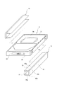
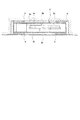
第1実施形態; 本発明の緩衝部材11,11をハードディスク装置2に取付ける状態を図1に示す。また、ハードディスク装置2に緩衝部材11,11を取付けた状態の正面図を図2に示す。ハードディスク装置2の右側に位置する緩衝部材11についてまず説明すると、この緩衝部材11は、ハードディスク装置2の筐体3の右側の長手側面3cを保持する側面保持部12を備えており、この側面保持部12は、上面3aや底面3bの面端から、上方または下方に突出している。また、この長手側面3cと連続する筐体の上面3aにおける縁部分を覆うように側面保持部12から片持ち梁状に突出し、筐体3の上面3aを保持する上面保持部13、および底面3bにおける縁部分を覆うように側面保持部12から片持ち梁状に突出し、筐体3の底面3bを保持する底面保持部14を備えている。上面保持部13の外側面13a、および底面保持部14の外側面14aは、側面保持部12の上端12aまたは下端12bから、筐体3の上面3aまたは底面3bの面内に向かって、各々傾斜面を形成している。また、上面保持部13と底面保持部14の肉厚(上下方向の厚さ)T2は、筐体3の上面3a及び底面3bからの側面保持部12の上下方向に沿う突出長さL3よりも薄く、薄肉に形成している。したがって、ノートPC1の格納部1aに収容する場合も、図3で示すように、側面保持部12の上端12aまたは下端12bは、格納部1aまたは格納部1aの蓋1bと接するが、上面保持部13や底面保持部14は格納部1aや蓋1bと接していない。ハードディスク装置2の左側に取付けられる緩衝部材11もまた、これと同じ構造を有している。
1st Embodiment; The state which attaches the
緩衝部材11の材料としては、硬度ショアA10〜70の弾性体を用いており、寸法精度、耐熱性、機械的強度、耐久性、信頼性、防振特性、制御特性などの要求性能に応じて、熱可塑性エラストマー、熱硬化性ゴム等から選択して用いることができる。硬度がショアA10より低いと、外部記憶装置を安定的に保持することが困難となり、ショアA70より高いと、要求する振動減衰効果が得られず、衝撃を緩衝することができない。熱可塑性エラストマーとしては、スチレン系熱可塑性エラストマー、オレフィン系熱可塑性エラストマー、ポリエステル系熱可塑性エラストマー、ポリウレタン系熱可塑性エラストマー、ポリアミド系熱可塑性エラストマー、塩化ビニル系熱可塑性エラストマー等を利用できる。また、熱硬化性ゴムとしては、天然ゴム、ブタジエンゴム、イソプレンゴム、スチレンブタジエン共重合ゴム、ニトリルゴム、水添ニトリルゴム、クロロプレンゴム、エチレンプロピレンゴム、塩素化ポリエチレン、クロロスルホン化ポリエチレン、ブチルゴム、ハロゲン化ブチルゴム、アクリルゴム、フッ素ゴム、ウレタンゴム、シリコーンゴム等を用いることができる。以上のような緩衝部材11にあっては、コンプレッション成形等によって作製することができる。
As the material of the
ハードディスク装置2の左右両長手側面3c、3cに緩衝部材11,11を取付け、ノートPC1の格納部1aに収納すれば、ハードディスク装置2の磁気ディスク2aの回転によって生じる内部振動も、ノートPC1の外部から伝わる外部振動も、緩衝部材11の押圧変形により吸収されて、緩和される。特に、外部からの振動が緩衝部材11を伝わる状態を、図3において矢印で模式的に示す。緩衝部材11は、上面保持部13と底面保持部14を、筐体3の上面3aと底面3bの面内方向に向けて徐々に薄肉に形成してあり、格納部1aまたは蓋1bと、側面保持部12の上端12aと下端12bが接触している。そのため、ノートPC1の格納部1aから伝わってくる振動は、この格納部1aと接している側面保持部12の上端12aにまず伝達される。その後、側面保持部12内を伝わり、さらに側面保持部12の下端12bを通じて蓋1bに伝達される。振動が、蓋1bから格納部1aへ伝達される場合も同様である。このように、外部から伝達される上下方向の振動は、緩衝部材11の側面保持部12内を伝わり、この側面保持部12で主に吸収、緩和される。そのため、上面保持部13や底面保持部14で支持されたハードディスク装置2には振動が伝わりにくくなっている。一方、水平方向の外部振動に対しても、側面保持部12が変位し易く、振動の吸収、衝撃の緩和がされ易い。そのため、自動車や電車の中でノートPC1を利用した場合に受ける振動や衝撃に対して優れた振動減衰、衝撃緩衝特性を発揮する。
If the
次に、本発明の他の実施形態について説明するが、第1実施形態で示した緩衝部材11と比較して材質や、形状等について同じ部分は説明を省略する。
Next, another embodiment of the present invention will be described. However, the description of the same parts of the material, the shape, and the like is omitted as compared with the
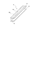
第2実施形態; 図4、図5で示した形状の緩衝部材21は、図1等で示した緩衝部材11の形状に対して、ハードディスク装置2の短手側面3d,3dを覆うカバー部25,15がさらに付加された形状をしている。側面保持部22、上面保持部23、底面保持部24などの保持部を有する点は第1実施形態で示した緩衝部材11と同様である。短手側面3dの縁側部分にまで端子が配置されたハードディスク装置2に対しては、短手側面3dを覆うことが困難でありカバー部25のない緩衝部材11等を用いることになるが、そのような端子が無い場合や、長手方向での衝撃を緩衝させる必要がある場合などにこの緩衝部材21が有効に用いられる。また、短手側面3d,3dをも被覆し、保持するため、ハードディスク装置2をより安定的に保持することができる。
Second Embodiment; The
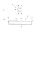
第3実施形態; 図6で示した形状の緩衝部材31は、上面保持部33,33や底面保持部34,34が、筐体3の上面3aまたは底面3bの縁全体を覆うものではなく、一部を覆うものである。そのため、上面保持部33,33や底面保持部34,34の大きさが小さく、緩衝部材31作製に要する弾性材が少なくて済むという利点がある。側面保持部32を有する点や、筐体3の上面3a及び底面3bからの側面保持部32の上下方向に沿う突出長さに対して、上面保持部33,33と底面保持部34,34の肉厚を薄肉に形成した点、そして、上面保持部33,33や底面保持部34,34の外側面33a,34aが傾斜面とされている点は、第1実施形態で示した緩衝部材11と同様である。
Third Embodiment: In the
第4実施形態; 図7で示した形状の緩衝部材41は、上面保持部43や底面保持部44の形状が、図1等で示した緩衝部材11とやや異なっている。上面保持部43の外側面43aは、側面保持部42との接合部から傾斜面となっているが、上面保持部43の先端付近では矩形状となっている。底面保持部44の形状も上面保持部43と同様である。側面保持部42を有する点や、筐体3の上面3a及び底面3bからの側面保持部42の上下方向に沿う突出長さに対して、上面保持部43と底面保持部44の肉厚を薄肉に形成した点は、第1実施形態で示した緩衝部材11と同様である。
Fourth Embodiment: The
第5実施形態; 第5実施形態による緩衝部材51も第1実施形態で示した緩衝部材11に対して上面保持部53や底面保持部54の形状が異なっているものであり、図8で示した形状をしている。この第5実施形態による緩衝部材51は、上面保持部53や底面保持部54の外側面53a,54aに傾斜面を有しないことで、側面保持部52が受ける衝撃がハードディスク装置2に伝達されにくい点で緩衝部材11等よりも優れている。一方、上面保持部53や底面保持部54の厚さが均一であるため、図1で示した緩衝部材11のような傾斜面を有する場合に比べて、上底面保持部53,54の側面保持部52側の厚さが相対的に薄くなる。そのため、衝撃を受けたときにハードディスク装置2が外れないように、緩衝部材11における上面保持部13や底面保持部14よりは、緩衝部材51の上面保持部53、底面保持部54を広面積に形成することが好ましい。
Fifth Embodiment: The
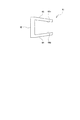
第6実施形態; 第6実施形態による緩衝部材61は、図9に示すように、上面保持部63の内側面63b、底面保持部64の内側面64bが、側面保持部62との接合部側から、傾斜状に形成されている。換言すれば、上面保持部63と底面保持部64を、側面保持部62に対して鋭角となるように形成されている。このため、直角に形成される場合よりも、ハードディスク装置2をより安定的に保持することができる。
Sixth Embodiment As shown in FIG. 9, the
第7実施形態; 第7実施形態による緩衝部材(図示せず)は、上面保持部および底面保持部の各外側面が階段状に形成され、上面保持部と底面保持部が、筐体の上面と底面の面内方向に向けて徐々に薄肉になっている。この緩衝部材もハードディスク装置2を安定的に保持することができる。
Seventh Embodiment; A buffer member (not shown) according to the seventh embodiment has stepped outer surfaces of the upper surface holding portion and the bottom surface holding portion, and the upper surface holding portion and the bottom surface holding portion are the upper surface of the housing. And gradually becomes thinner toward the in-plane direction of the bottom. This buffer member can also hold the
第8実施形態による緩衝部材(図示せず)は、短手側面3d,3dの両面を覆うカバー部25,25を備えた緩衝部材21に対して、そのどちらか一方のカバー部25を有しない形状としたものである。このような緩衝部材とすれば、ハードディスク装置2の4隅のコーナーに設置して用いることができる。以上の実施形態以外のさらに別の実施形態としては、カバー部25を有しない緩衝部材31,41,51にカバー部を設けるような形状の緩衝部材を挙げることができる。
The shock-absorbing member (not shown) according to the eighth embodiment does not have one of the
以上説明した緩衝部材11,21,31,41,51,61においては、ハードディスク装置2の少なくとも長手側面3cと上底面3a,3bを覆う保持部を有するものとして説明したが、格納部1aへのハードディスク装置2の設置向きや、設置スペースなどによっては、短手側面3dと上底面3a,3bを覆うものとしたり、上面3a又は底面3bと、2つの長手側面3c,3cを覆うものとするなどの変更が可能である。即ち、縦置きや横置きなどハードディスク装置2を使用する姿勢に応じて適宜、緩衝部材を取付ける面を選択することができる。ただし、緩衝部材の各保持部やカバー部の大きさは、その場合ごとに変わりうる。
In the
また、緩衝部材11,31,41,51,61等の長手方向の長さを短くした緩衝部材を用いることにより、例えば図10で示すように、一側面に2以上の緩衝部材71を配置することも可能である。さらに、隣接する側面どうしに緩衝部材を配置することも可能である(図示せず)。
Further, by using a buffer member having a reduced length in the longitudinal direction, such as the
なお、本発明の緩衝部材の種々の実施形態や利用例について説明したが、本発明の緩衝部材やその用い方はこれらの例に限定されるものではなく、適宜変更が可能である。 In addition, although various embodiment and the usage example of the buffer member of this invention were demonstrated, the buffer member of this invention and how to use it are not limited to these examples, and can be changed suitably.
1 ノートPC(情報処理装置)
1a 格納部
1b 蓋
2 ハードディスク装置(外部記憶装置)
2a 磁気ディスク
2b 磁気ヘッド
3 筐体
3a 上面
3b 底面
3c 長手側面
3d 短手側面
4 シート状緩衝部材(従来例)
5 ネジ
11,21,31,41,51,61,71 緩衝部材
12,22,32,42,52,62 側面保持部
12a,22a,32a,42a,52a 上端
12b,22b 下端
13,23,33,43,53,63 上面保持部
13a,33a,43a,53a (上面保持部の)外側面
63b (上面保持部の)内側面
14,24,34,44,54,64 底面保持部
14a,34a,54a (底面保持部の)外側面
64b (底面保持部の)内側面
25 カバー部
1 Notebook PC (information processing device)
DESCRIPTION OF
2a
5
Claims (9)
外部記憶装置の筐体の側面を保持する側面保持部と、側面保持部から片持ち梁状に突出し該筐体の上面を保持する上面保持部と、側面保持部から片持ち梁状に突出し該筐体の底面を保持する底面保持部と、を有する保持部を備え、
上面保持部と底面保持部を、筐体の上面及び底面からそれぞれ上下方向に突出する側面保持部のその突出した長さに対して肉厚を薄肉にして情報処理装置に接触しないものとし、
側面保持部を、筐体の上面及び底面からそれぞれ上下方向に突出して情報処理装置に接触する上端と下端とを有するものとし、
側面保持部の上端と下端を通じて伝達された振動を吸収し緩和することを特徴とする緩衝部材。 Elastic material of the housing to be interposed in a gap between the storage unit of the information processing apparatus to accommodate the external storage device of the external storage device Toko for accommodating the disc-shaped recording medium to absorb vibration and floatingly supported the external storage device relaxation In the buffer member,
A side surface holding portion that holds the side surface of the housing of the external storage device, a top surface holding portion that protrudes in a cantilever shape from the side surface holding portion, and a protrusion that protrudes in a cantilever shape from the side surface holding portion. A bottom holding part for holding the bottom of the housing, and a holding part having
The upper surface holding part and the bottom surface holding part shall not be in contact with the information processing device by making the wall thickness thin relative to the protruding length of the side surface holding part protruding vertically from the upper surface and the bottom surface of the housing ,
The side surface holding portion has an upper end and a lower end that protrude in the vertical direction from the upper surface and the bottom surface of the housing and contact the information processing device, respectively.
A shock absorbing member that absorbs and reduces vibration transmitted through the upper and lower ends of the side surface holding portion .
外部記憶装置を収容する情報処理装置と、An information processing apparatus that accommodates an external storage device;
外部記憶装置と情報処理装置の格納部との隙間に介在させて外部記憶装置を浮動支持して振動を吸収し緩和する弾性材でなる緩衝部材と、を備える外部記憶装置への振動緩衝構造において、In a vibration damping structure for an external storage device, comprising: a buffer member made of an elastic material that absorbs and relieves vibration by floatingly supporting the external storage device by interposing it in a gap between the external storage device and the storage unit of the information processing device ,
緩衝部材が、外部記憶装置の筐体の側面を保持する側面保持部と、側面保持部から片持ち梁状に突出し該筐体の上面を保持する上面保持部と、側面保持部から片持ち梁状に突出し該筐体の底面を保持する底面保持部と、を有する保持部を備え、The buffer member has a side surface holding portion that holds the side surface of the housing of the external storage device, a top surface holding portion that protrudes in a cantilever shape from the side surface holding portion, and a cantilever beam from the side surface holding portion. A holding part having a bottom holding part protruding in a shape and holding the bottom face of the housing,
上面保持部と底面保持部を、筐体の上面及び底面からそれぞれ上下方向に突出する側面保持部のその突出した長さに対して肉厚を薄肉にして情報処理装置に接触しないものとし、The upper surface holding part and the bottom surface holding part shall not be in contact with the information processing device by making the wall thickness thin relative to the protruding length of the side surface holding part protruding vertically from the upper surface and the bottom surface of the housing,
側面保持部を、筐体の上面及び底面からそれぞれ上下方向に突出して情報処理装置に接触する上端と下端とを有するものとし、The side surface holding portion has an upper end and a lower end that protrude in the vertical direction from the upper surface and the bottom surface of the housing and contact the information processing device, respectively.
側面保持部の上端と下端を通じて伝達された振動を吸収し緩和することを特徴とする外部記憶装置への振動緩衝構造。A vibration buffering structure for an external storage device that absorbs and relieves vibration transmitted through the upper and lower ends of the side surface holding portion.
Priority Applications (1)
| Application Number | Priority Date | Filing Date | Title |
|---|---|---|---|
| JP2003275962A JP4376567B2 (en) | 2003-07-17 | 2003-07-17 | Buffer member for external storage device |
Applications Claiming Priority (1)
| Application Number | Priority Date | Filing Date | Title |
|---|---|---|---|
| JP2003275962A JP4376567B2 (en) | 2003-07-17 | 2003-07-17 | Buffer member for external storage device |
Publications (2)
| Publication Number | Publication Date |
|---|---|
| JP2005038538A JP2005038538A (en) | 2005-02-10 |
| JP4376567B2 true JP4376567B2 (en) | 2009-12-02 |
Family
ID=34212436
Family Applications (1)
| Application Number | Title | Priority Date | Filing Date |
|---|---|---|---|
| JP2003275962A Expired - Lifetime JP4376567B2 (en) | 2003-07-17 | 2003-07-17 | Buffer member for external storage device |
Country Status (1)
| Country | Link |
|---|---|
| JP (1) | JP4376567B2 (en) |
Families Citing this family (6)
| Publication number | Priority date | Publication date | Assignee | Title |
|---|---|---|---|---|
| JP4944528B2 (en) * | 2006-07-25 | 2012-06-06 | ポリマテック株式会社 | Buffer member |
| JP2008171515A (en) * | 2007-01-15 | 2008-07-24 | Polymatech Co Ltd | Cushioning material |
| JP4847414B2 (en) | 2007-08-09 | 2011-12-28 | 富士通株式会社 | Electronic component mounting parts and electronic equipment |
| JP2009087455A (en) * | 2007-09-28 | 2009-04-23 | Polymatech Co Ltd | Buffer component |
| JP2009272018A (en) * | 2008-05-09 | 2009-11-19 | Fujitsu Ten Ltd | Device for mounting electronic device |
| TWI519228B (en) * | 2012-05-25 | 2016-01-21 | 樺漢科技股份有限公司 | Fixing apparatus for hard disk drive |
-
2003
- 2003-07-17 JP JP2003275962A patent/JP4376567B2/en not_active Expired - Lifetime
Also Published As
| Publication number | Publication date |
|---|---|
| JP2005038538A (en) | 2005-02-10 |
Similar Documents
| Publication | Publication Date | Title |
|---|---|---|
| US7486509B2 (en) | Bracket for disk drive | |
| US6166901A (en) | Vibration dampening system for removable hard disk drive carriers | |
| US6324054B1 (en) | Wrap around shock absorber for disc drives | |
| US20030174464A1 (en) | Information storage device | |
| JPH10222972A (en) | Storage device and impact resistant accommodation container to be used therefor | |
| US6021041A (en) | Tuned shock absorbing system for portable computer hard disc drives | |
| JP2009264483A (en) | Shock absorbing member | |
| JP4376567B2 (en) | Buffer member for external storage device | |
| JP4193463B2 (en) | Information storage device | |
| US4647998A (en) | Transducer head assembly | |
| JP2005018835A (en) | Buffer member for external storage device | |
| JP4169148B2 (en) | Buffer member mounting structure | |
| US8035960B2 (en) | Hard disk drive frame | |
| US20020085309A1 (en) | Disk drive shock absorption mechanism | |
| WO2010016096A1 (en) | Disc type recording medium drive device and electronic device using the same | |
| JP2009272018A (en) | Device for mounting electronic device | |
| JPS63138588A (en) | Data memory device | |
| JP4382428B2 (en) | Magnetic disk unit | |
| JP4185559B2 (en) | Electronic device and mounting mechanism | |
| JP4147937B2 (en) | Edge damper | |
| CN216849323U (en) | Thin vehicle-mounted mechanical hard disk damping device | |
| CN219980918U (en) | Driving device, camera module and electronic equipment | |
| JP4900182B2 (en) | Shock absorber and information processing apparatus having the shock absorber | |
| JP2009059423A (en) | Optical disk apparatus | |
| KR20040083306A (en) | Disk Drive System Equipped with Damping Structure |
Legal Events
| Date | Code | Title | Description |
|---|---|---|---|
| A621 | Written request for application examination |
Free format text: JAPANESE INTERMEDIATE CODE: A621 Effective date: 20060620 |
|
| A977 | Report on retrieval |
Free format text: JAPANESE INTERMEDIATE CODE: A971007 Effective date: 20081016 |
|
| A131 | Notification of reasons for refusal |
Free format text: JAPANESE INTERMEDIATE CODE: A131 Effective date: 20090120 |
|
| A521 | Written amendment |
Free format text: JAPANESE INTERMEDIATE CODE: A523 Effective date: 20090319 |
|
| A131 | Notification of reasons for refusal |
Free format text: JAPANESE INTERMEDIATE CODE: A131 Effective date: 20090421 |
|
| TRDD | Decision of grant or rejection written | ||
| A01 | Written decision to grant a patent or to grant a registration (utility model) |
Free format text: JAPANESE INTERMEDIATE CODE: A01 Effective date: 20090818 |
|
| A01 | Written decision to grant a patent or to grant a registration (utility model) |
Free format text: JAPANESE INTERMEDIATE CODE: A01 |
|
| A61 | First payment of annual fees (during grant procedure) |
Free format text: JAPANESE INTERMEDIATE CODE: A61 Effective date: 20090909 |
|
| R150 | Certificate of patent or registration of utility model |
Free format text: JAPANESE INTERMEDIATE CODE: R150 |
|
| FPAY | Renewal fee payment (event date is renewal date of database) |
Free format text: PAYMENT UNTIL: 20120918 Year of fee payment: 3 |