JP4375556B2 - Document feeder - Google Patents
Document feeder Download PDFInfo
- Publication number
- JP4375556B2 JP4375556B2 JP2004251941A JP2004251941A JP4375556B2 JP 4375556 B2 JP4375556 B2 JP 4375556B2 JP 2004251941 A JP2004251941 A JP 2004251941A JP 2004251941 A JP2004251941 A JP 2004251941A JP 4375556 B2 JP4375556 B2 JP 4375556B2
- Authority
- JP
- Japan
- Prior art keywords
- document
- roller
- reading
- conveying
- driving roller
- Prior art date
- Legal status (The legal status is an assumption and is not a legal conclusion. Google has not performed a legal analysis and makes no representation as to the accuracy of the status listed.)
- Expired - Fee Related
Links
Images


Description
本発明は、搬送される原稿の画像を読取位置で読取る読取手段を有する画像読取装置に搭載される原稿搬送装置に関するものであって、1枚の原稿の読み取り中に、原稿の搬送を中断、または原稿の搬送速度を変化させる原稿搬送装置に関するものである。 The present invention relates to a document conveying device mounted on an image reading apparatus having a reading unit that reads an image of a conveyed document at a reading position, and interrupts the conveyance of the document while reading one document. Alternatively, the present invention relates to an original conveying apparatus that changes an original conveying speed.
一般的に、静止する原稿の画像記録面の読み取りだけでなく、搬送される原稿の画像記録面も読み取ることができる画像読取装置においては、それぞれの画像読取に対応して、静止原稿用と搬送原稿用の2種の透明板(ガラス板)が画像読取装置の本体の上部に設けられている。そして、静止原稿は、本体に対して開閉可能な蓋状カバー体で押えられて、静止原稿用透明板(フラットベッド)の下面に沿って移動するイメージスキャナ(読取手段)にて原稿の画像記録面が読み取られる。他方、搬送される原稿を読み取る場合には、蓋状カバー体の上面に備えられた自動原稿搬送装置により、給紙トレイ上に堆積された複数枚の原稿を1枚ずつ分離しながら搬送原稿用透明板上に搬送し、この搬送原稿用透明板の下方に静止された読取手段にて原稿の画像記録面を読み取った後、排紙トレイ部に排出するように構成されている。 In general, in an image reading apparatus that can read not only the image recording surface of a stationary document but also the image recording surface of a document that is being conveyed, it can be used for both a stationary document and a conveyance corresponding to each image reading. Two types of transparent plates (glass plates) for originals are provided on the upper part of the main body of the image reading apparatus. Then, the stationary document is pressed by a lid-like cover body that can be opened and closed with respect to the main body, and the document image is recorded by an image scanner (reading means) that moves along the lower surface of the stationary document transparent plate (flat bed). The surface is read. On the other hand, when reading a document to be conveyed, an automatic document conveying device provided on the upper surface of the lid-like cover body separates a plurality of documents deposited on the paper feed tray one by one. It is configured so that it is transported onto a transparent plate, the image recording surface of the document is read by a reading means stationary below the transported document transparent plate, and then discharged onto a paper discharge tray portion.
搬送される原稿を読み取る場合の自動原稿搬送装置は、特許文献1に示すように、上部側に配置された原稿の給紙部から原稿読取位置を経て下方側に配置された排紙部に至る略Uターン形状の原稿搬送路を有するいわゆる上給紙方式の自動原稿搬送装置と、特許文献2に示すように、下部側に配置された原稿の給紙部から原稿読取位置を経て上方側に配置された排紙部に至る略Uターン形状の原稿搬送路を有するいわゆる下給紙方式の自動原稿搬送装置とに大別でき、いずれも装置全体の小型化のために略Uターン形状の反転用の原稿搬送路を備えている。
As shown in
そして、これらの自動原稿搬送装置では、正確な原稿搬送を行うために、原稿搬送路に沿って複数の搬送用ローラを備えている。搬送用ローラとしては、駆動源により駆動される駆動ローラと、この駆動ローラに従動するように対向配置される従動ローラとが設けられ、略Uターン形状の原稿搬送路でも、その反転の円弧に沿った高精度な搬送を行うために、複数の駆動ローラが配置されている。 These automatic document conveying devices are provided with a plurality of conveying rollers along the document conveying path in order to accurately convey the document. As the conveying rollers, there are provided a driving roller driven by a driving source and a driven roller disposed so as to be driven to follow the driving roller. Even in a substantially U-turn shaped document conveying path, a reverse arc is provided. A plurality of drive rollers are arranged in order to perform high-precision conveyance along.
しかしながら、略Uターン形状の原稿搬送路では、搬送用ローラの数が多くなると部品コストが嵩み、また、複数の駆動ローラの各々の直径のバラツキにより回転速度が異なり、そのバラツキが原稿の搬送に悪影響を及ぼすことが問題であった。 However, in the substantially U-turn-shaped document conveying path, the cost of parts increases as the number of conveying rollers increases, and the rotational speed varies depending on the variation in the diameter of each of the plurality of driving rollers. It was a problem to adversely affect
ところで、搬送用ローラでは、原稿の滑りによる搬送速度や搬送量の乱れを防止するために、駆動ローラと従動ローラとを弾力的に当接させる技術が知られている。 By the way, in the conveyance roller, in order to prevent the disturbance of the conveyance speed and the conveyance amount due to the slippage of the document, a technique in which the driving roller and the driven roller are elastically contacted is known.
そこで、本出願人は、略Uターン形状の原稿搬送路を、大径に形成された1つの反転駆動ローラの周面で構成して簡略化を図るとともに、この大径の反転駆動ローラをその駆動軸にゴム状弾性材からなるローラ体を被嵌して一体的に回転するように形成し、且つ反転駆動ローラの周囲に、反転駆動ローラ側に付勢した複数の従動ローラを配置して、原稿搬送の高精度化を図った。前述した大径の反転駆動ローラの製造においては、駆動軸の直径を大きくして大径とする形態と、駆動軸に被嵌するローラ体を肉厚にして大径にする形態とが考えられるが、前者の形態では、駆動軸の製造コストが高くなるため、本出願人は後者の形態を採用した。
しかしながら、大径の反転駆動ローラを後者の形態のようにローラ体を肉厚にする、すなわちローラ体の軸線に直交する方向の厚みを厚くして形成すると、ローラ体のゴム状弾性部材は、駆動軸に固定された箇所(固定端に相当)から、原稿に当接する箇所(自由端に相当)までの長さが長くなることになる。そのため、給紙トレイから原稿を1枚ずつ分離するための分離装置が反転駆動ローラの搬送方向上流側に存在すると、給紙トレイに載置された原稿を分離するための分離装置の摩擦力が原稿に対してのバックテンションとなり、原稿はローラ体の最外周に巻きつく形で搬送されるので、反転駆動ローラの駆動軸が原稿を搬送しようと回転するとき、そのバックテンションがローラ体をねじる力となってローラ体に加えられることになる。そして、ローラ体はゴム状弾性部材で形成されているので、その弾性変形によって駆動軸の回転に対して原稿(ローラ体の外周)は駆動開始初期に所定量(ローラ体に発生したねじれによる復元力がバックテンションと釣り合う量)だけ遅れて回転を開始することになる。 However, when the large-diameter reversal drive roller is formed with a thickened roller body as in the latter form, that is, with a thicker thickness in the direction perpendicular to the axis of the roller body, the rubber-like elastic member of the roller body is The length from a portion fixed to the drive shaft (corresponding to the fixed end) to a portion contacting the document (corresponding to the free end) becomes long. For this reason, when a separation device for separating the documents one by one from the paper feed tray exists on the upstream side in the transport direction of the reverse drive roller, the frictional force of the separation device for separating the documents placed on the paper feed tray is increased. Since the back tension is applied to the original and the original is wound around the outermost periphery of the roller body, when the drive shaft of the reverse drive roller rotates to convey the original, the back tension twists the roller body. The force is applied to the roller body. Since the roller body is formed of a rubber-like elastic member, the original (the outer circumference of the roller body) is restored by a predetermined amount (restoration caused by the twist generated in the roller body) with respect to the rotation of the drive shaft due to the elastic deformation. The rotation will be delayed by an amount that balances the back tension.
ところで、原稿の読み取りにおいては、1枚の原稿を一定速度で最初から最後まで一度も停止せずに読み取ることができずに、途中で一時停止したり、読取速度を落としたりすることがある。例えば、ファクシミリ通信を行う際に、様々な理由によりバッファとしてのメモリが不足し、読み取りデータの受け取り側(受信側)の処理スピードが遅かったり、通信状態が悪く、遅い通信速度でしか送信できなくなると、1枚の原稿の読み取り中に、一旦原稿搬送を停止(処理が間に合わないので新たなデータの発生を停止する)したり、搬送速度を遅くして処理時間を稼いだりすることがある。カラー通信のように読取のデータ量そのものが大量になる場合も同様である。 By the way, in reading a document, a single document cannot be read without stopping from the beginning to the end at a constant speed, and may be temporarily stopped or the reading speed may be reduced. For example, when performing facsimile communication, the memory as a buffer is insufficient for various reasons, the processing speed on the receiving side (receiving side) of read data is slow, the communication state is poor, and transmission is possible only at a slow communication speed. In addition, during the reading of a single document, document transportation may be temporarily stopped (the generation of new data is stopped because the processing is not in time), or the processing speed may be increased by slowing the transportation speed. The same is true when the amount of data to be read is large, such as color communication.
この場合、一旦原稿が停止することになるため、原稿の移動に伴って発生するバックテンションが小さくなり、ローラ体に発生したねじれによる復元力との釣り合いが崩れることになる。 In this case, since the document is once stopped, the back tension generated along with the movement of the document is reduced, and the balance with the restoring force due to the twist generated in the roller body is lost.
その結果、反転駆動ローラの駆動軸は駆動源によって固定されている形になるので、ローラ体の外周部はローラ体に発生したねじれを解消するべく、わずかに原稿を前進(搬送方向下流側へ搬送)させる方向に回転し、その回転により原稿もわずかに移動する現象が、本出願人の実験によって確認されている。 As a result, the drive shaft of the reverse drive roller is fixed by the drive source, so that the outer peripheral portion of the roller body advances the document slightly (downward in the conveyance direction) in order to eliminate the twist generated in the roller body. It has been confirmed by the applicant's experiment that the document rotates slightly in the direction in which the document is conveyed and the document moves slightly due to the rotation.
そして、データ処理が進みバッファメモリの空きができると、原稿の読み取りを再開するのであるが、停止中に原稿がわずかに前進しているために、読み取り中に停止した場所から読取を再開することができなくなってしまうのである。 When the data processing progresses and the buffer memory is free, the reading of the original is resumed. However, since the original is slightly advanced during the stop, the reading is resumed from the place where the reading was stopped. It will not be possible.
このように、1枚の原稿を読み取る間に、原稿搬送の一時停止と再開を繰り返す場合には、原稿の停止時に搬送量の乱れが発生し、結果として読取性能が悪化する現象が発生していたのである。 As described above, when the document conveyance is repeatedly paused and restarted while reading one document, the conveyance amount is disturbed when the document is stopped, resulting in a phenomenon that the reading performance deteriorates. It was.
本発明は、上記問題を解決することを第1の技術的課題とし、原稿の読取性能をさらに向上させる原稿搬送装置の実現を第2の技術的課題とするものである。 It is a first technical object of the present invention to solve the above problems, and a second technical problem is to realize a document conveying device that further improves document reading performance.
前記課題を解決するために、請求項1に記載の発明における原稿搬送装置は、所定の搬送方向に搬送される原稿の画像を読取位置で読み取る読取手段を有する画像記録装置に搭載され、給紙トレイ部から前記読取位置を経て排紙トレイ部まで原稿を搬送する原稿搬送路が備えられ、1枚の原稿の読み取り中に、原稿の搬送を一時停止、または原稿の搬送速度を変化させる原稿搬送装置において、前記給紙トレイ部に堆積状態にて載置された複数の原稿から1枚の原稿を搬送するための、第1の駆動ローラとこれに弾力的に当接可能な第1の当接部材とを備える分離・搬送手段と、この分離・搬送手段によって搬送されてきた原稿を読取位置を通して排紙トレイ部へさらに搬送するための、第2の駆動ローラとこれに弾力的に当接可能な第2の当接部材とを備える搬送手段とを有し、前記第2の駆動ローラは、駆動軸にゴム状弾性体からなるローラ体が被嵌されて一体的に回転するように形成されて、前記ローラ体の外周面が前記読取手段の読取面に対向して配置され、前記第2の駆動ローラには、原稿の搬送時における前記ローラ体の円周方向の弾性変形によるねじれを抑制する拘束部材が取り付けられ、前記拘束部材は、前記ローラ体の外周と同心円状で且つ該外周より小径の外周を有する薄板状の部材であり、前記ローラ体の軸方向の両端面に取り付けられていることを特徴とするものである。 In order to solve the above-described problem, the document conveying device according to the first aspect of the present invention is mounted on an image recording apparatus having a reading unit that reads an image of a document conveyed in a predetermined conveying direction at a reading position, A document transport path for transporting a document from the tray section to the discharge tray section through the reading position is provided, and the document transport for temporarily stopping the document transport or changing the document transport speed while reading one document. In the apparatus, a first driving roller for conveying one original from a plurality of originals placed in a stacked state on the paper feed tray and a first contact roller that can be elastically contacted with the first driving roller. A separating / conveying means having a contact member; and a second driving roller for resiliently abutting the second driving roller for further conveying the original conveyed by the separating / conveying means to the discharge tray portion through the reading position. Possible second And the second driving roller is formed so that a roller body made of a rubber-like elastic body is fitted on the driving shaft so as to rotate integrally, and the roller body The second driving roller is provided with a restraining member that suppresses torsion caused by elastic deformation in the circumferential direction of the roller body during conveyance of the document. The constraining member is a thin plate-like member that is concentric with the outer periphery of the roller body and has a smaller outer diameter than the outer periphery, and is attached to both axial end surfaces of the roller body. To do.
請求項2に記載の発明は、請求項1に記載の原稿搬送装置において、前記拘束部材は、前記駆動軸の外径に略等しい内径を有する環状の円板であることを特徴とするものである。 According to a second aspect of the present invention, in the document conveying device according to the first aspect, the restraining member is an annular disk having an inner diameter substantially equal to an outer diameter of the drive shaft. is there.
請求項3に記載の発明は、請求項1または2に記載の原稿搬送装置において、前記拘束部材の外径と、前記ローラ体の外径とが近接していることを特徴とするものである。 According to a third aspect of the present invention, in the document conveying device according to the first or second aspect , the outer diameter of the restraining member and the outer diameter of the roller body are close to each other. .
請求項4に記載の発明は、請求項1乃至3のいずれかに記載の原稿搬送装置において、前記拘束部材はローラ体に固着または接着されていることを特徴とするものである。 According to a fourth aspect of the present invention, in the document conveying device according to any one of the first to third aspects, the restraining member is fixed or bonded to a roller body.
請求項5に記載の発明は、請求項1乃至4のいずれかに記載の原稿搬送装置において、前記原稿搬送路は、第1の搬送方向と第2の搬送方向とからなる略Uターン形状を有し、前記搬送手段は、前記分離・搬送手段によって第1の搬送方向に沿って搬送されてきた原稿を前記第2の搬送方向に反転させ、前記第2の駆動ローラは、その外周面が前記読取面に対向し、且つ回転中心が前記原稿搬送路の略Uターン形状における反転の中心に略一致するように配置され、前記第2の駆動ローラのローラ体の外周の半径は、前記略Uターン形状における反転の回転半径に略等しいことを特徴とするものである。 According to a fifth aspect of the present invention, in the document conveying apparatus according to any one of the first to fourth aspects, the document conveying path has a substantially U-turn shape including a first conveying direction and a second conveying direction. And the conveying means reverses the document conveyed along the first conveying direction by the separating / conveying means in the second conveying direction, and the second driving roller has an outer peripheral surface thereof. It is arranged so as to face the reading surface and the center of rotation substantially coincides with the center of reversal in the substantially U-turn shape of the document conveying path, and the radius of the outer periphery of the roller body of the second driving roller is the approximately It is characterized by being approximately equal to the turning radius of reversal in the U-turn shape.
請求項6に記載の発明は、請求項1乃至5のいずれかに記載の原稿搬送措置において、前記第2の駆動ローラの外周面から一時的に原稿を離間させて前記読取位置での原稿の挙動を規制するとともに、前記第2の駆動ローラを露出させる露出部を有する規制手段を備え、この規制手段と前記第2の駆動ローラとの間隙が前記読取手段側へ露出するを防止するための露出防止手段が設けられていることを特徴とするものである。 According to a sixth aspect of the present invention, there is provided the document conveying measure according to any one of the first to fifth aspects, wherein the document is temporarily separated from the outer peripheral surface of the second drive roller and the document at the reading position is scanned. A regulating means for regulating the behavior and having an exposed portion for exposing the second driving roller is provided, and a gap between the regulating means and the second driving roller is prevented from being exposed to the reading means side. An exposure prevention means is provided.
請求項7に記載の発明は、請求項6に記載の原稿搬送装置において、前記規制手段は、前記第2の駆動ローラの駆動軸に吊支されていることを特徴とするものである。 According to a seventh aspect of the present invention, in the document conveying device according to the sixth aspect , the restricting means is suspended from a drive shaft of the second drive roller.
請求項1に記載の発明によれば、第2の駆動ローラに拘束部材が取り付けられて、ローラ体の円周方向へのねじれが抑制されているから、原稿の読み取り中に、原稿の搬送を中断または原稿の搬送速度を変化させているときの、前記ねじれの復元に伴って発生する原稿の搬送量の乱れを防止することができ、原稿の読取性能を向上させることができる。 According to the first aspect of the present invention, since the restraining member is attached to the second drive roller to prevent the roller body from being twisted in the circumferential direction, the document can be conveyed while the document is being read. It is possible to prevent disturbance of the document conveyance amount that occurs due to the restoration of the twist when the interruption or the document conveyance speed is changed, and the document reading performance can be improved.
また、請求項1に記載の発明によれば、拘束部材は、ローラ体の軸方向の両端面側からローラ体の弾性変形を拘束するから、ローラ体の円周方向に生じるねじれに対する拘束性が高められる。また、拘束部材の外周は、ローラ体の外周と同心円状であるから、ローラ体の円周に対して均等な拘束力が発揮される。 According to the first aspect of the present invention, since the restraining member restrains the elastic deformation of the roller body from both end surfaces in the axial direction of the roller body, the restraining member has a restraining property against the twist generated in the circumferential direction of the roller body. Enhanced. Further, since the outer periphery of the restraining member is concentric with the outer periphery of the roller body, a uniform restraining force is exerted on the circumference of the roller body.
請求項2に記載の発明によれば、環状の拘束部材を駆動軸の外周に合わせて被嵌できるから、拘束部材をローラ体の端面へ取り付けるに際して位置決めが容易になる効果を奏する。 According to the second aspect of the present invention, since the annular restraining member can be fitted in accordance with the outer periphery of the drive shaft, there is an effect that positioning becomes easy when the restraining member is attached to the end surface of the roller body.
請求項3に記載の発明によれば、ローラ体において、拘束部材に拘束されずに自由に弾性変形できる領域が大幅に減少させられるので、拘束部材によるねじれ抑制の効果が大きく向上される。 According to the third aspect of the present invention, in the roller body, the region that can be freely elastically deformed without being restrained by the restraining member is greatly reduced, so that the effect of suppressing twisting by the restraining member is greatly improved.
請求項4に記載の発明によれば、固着または接着により拘束部材が強固にローラ体に取り付けられるため、ローラ体に対する拘束性が高められる。 According to the fourth aspect of the present invention, since the restraining member is firmly attached to the roller body by adhering or adhering, the restraining property on the roller body is improved.
請求項5に記載の発明によれば、原稿搬送路用の略Uターン形状が第2の駆動ローラの周面を利用して構成される、換言すれば、略Uターン形状の反転の中心軸上に、少なくとも1つの反転駆動ローラを配置するだけで反転搬送路を構成できるから、装置の簡略化によるコストダウンが可能となる。 According to the fifth aspect of the present invention, the substantially U-turn shape for the document conveyance path is configured by using the peripheral surface of the second drive roller, in other words, the central axis of the reversal of the substantially U-turn shape. In addition, since the reverse conveyance path can be configured only by arranging at least one reverse drive roller, the cost can be reduced by simplifying the apparatus.
請求項6に記載の発明によれば、露出防止手段によって、規制手段と第2の駆動ローラとの間隙が読取手段側へ露出するのを防止されているから、原稿の厚みが薄い場合でも前記間隙が透けて読み取りに悪影響を与えることを防止でき、画像の読取性能を向上させることができる。 According to the sixth aspect of the present invention, since the gap between the restricting means and the second drive roller is prevented from being exposed to the reading means side by the exposure preventing means, even when the original is thin, It is possible to prevent the gap from being seen and adversely affect the reading, and the image reading performance can be improved.
請求項7に記載の発明によれば、前記規制手段は駆動軸に吊支されているから、規制手段の下面が反転駆動ローラの外周面から原稿を一時的に離間させるようにする取付位置を正確に且つ容易に設定できるという効果を奏する。 According to the seventh aspect of the present invention, since the restricting means is suspended from the drive shaft, the lower surface of the restricting means has an attachment position for temporarily separating the document from the outer peripheral surface of the reverse drive roller. There is an effect that it can be set accurately and easily.
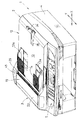
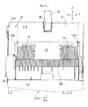
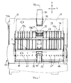
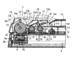
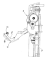
以下、本発明を実施するための最良の形態について図面に基づいて説明する。図1は本発明の画像読取装置を備えた多機能装置の斜視図、図2は平面図、図3は原稿搬送装置(ADF)における原稿搬送経路を覆うカバー部材としての搬送部カバー体を開いた(開放した)状態の斜視図、図4は搬送部カバー体を大きく開いた状態の平面図、図5(a)は画像読取装置の図2のVa−Va線矢視断面図、図5(b)は画像読取装置の図4のVb−Vb線矢視断面図、図6は図5(a)の要部拡大断面図、図7は画像読取位置での原稿をガラス板に押圧する押圧部材及び従動ローラを押圧・離間させる手段の箇所を示す拡大断面図、図8は搬送部カバー体を開放した状態の拡大平面図、図9は図8のIX−IX線矢視拡大断面図、図10は駆動系を示す図、図11は反転ローラ及び押圧部材等の箇所を示す拡大斜視図、図12は静止原稿を押圧する押圧板等の斜視図、図13は原稿の堆積順序を正順にする手段を示す要部拡大側断面図、図14は図13のXIV −XIV 線矢視断面図、図15は読取手段側から反転駆動ローラを見た状態を示す模式図である。 The best mode for carrying out the present invention will be described below with reference to the drawings. FIG. 1 is a perspective view of a multi-function device provided with an image reading device of the present invention, FIG. 2 is a plan view, and FIG. 3 is an illustration of an opening of a transport unit cover body as a cover member covering a document transport path in a document transport device (ADF). FIG. 4 is a plan view of a state in which the transport unit cover body is greatly opened, FIG. 5A is a cross-sectional view of the image reading device taken along the line Va-Va in FIG. 4B is a cross-sectional view taken along the line Vb-Vb of FIG. 4 of the image reading apparatus, FIG. 6 is an enlarged cross-sectional view of the main part of FIG. 5A, and FIG. 7 presses the document at the image reading position against the glass plate. 8 is an enlarged cross-sectional view showing the location of the means for pressing / separating the pressing member and the driven roller, FIG. 8 is an enlarged plan view in a state in which the transport section cover body is opened, and FIG. 9 is an enlarged cross-sectional view taken along line IX-IX in FIG. FIG. 10 is a diagram showing a drive system, FIG. 11 is an enlarged perspective view showing parts such as a reversing roller and a pressing member, and FIG. FIG. 13 is an enlarged side sectional view showing the main part of the document stacking order, FIG. 14 is a sectional view taken along line XIV-XIV in FIG. 13, and FIG. 15 is the reading means side. It is a schematic diagram which shows the state which looked at the reverse drive roller from.
本発明の実施形態は、ファクシミリ機能、スキャナ機能、複写機能及びプリンタ機能を備えた多機能装置1における画像読取装置2とその原稿搬送装置3に適用したものである。
The embodiment of the present invention is applied to the
図1及び図2に示すように、多機能装置1の本体ケース4の上面には、その前寄り部位に、ファクシミリ機能、スキャナ機能、複写機能を実行するためのテンキーや各種作業を指令するためのボタンキー、指令内容表示やエラー表示等を行う液晶パネルなどを備えた操作パネル部5が配置されている。操作パネル部5の後方には、スキャナ機能を実行するための画像読取装置2とそれに搭載される原稿搬送装置3とが配置されている。図5(a)及び図5(b)に示すように、画像読取装置2におけるケース2a上には静止原稿載置用及び搬送原稿用の透明板部材として兼用されるガラス板6が配置されている。ガラス板6の下方には、原稿の画像記録面を読取るためのライン形の読取手段8(例えば、密着形イメージセンサ:CIS(Contact Image Sensor)等)を備えている。図1のX方向に沿った直線状のガイド軸9に載置されて往復移動可能なライン形の読取手段8は図1のY方向に直線的に長く形成されている。
As shown in FIGS. 1 and 2, on the upper surface of the
画像読取装置2におけるケース2aはその一側端部(実施形態では、図1及び図2の左側端)側で本体ケース4に水平に設けられた枢軸7(図5(a)及び図5(a)参照)を中心に上下回動可能に装着されている。
The
画像読取装置2に対して原稿を搬送する原稿搬送装置3(自動原稿供給装置(ADF)ともいう)は、ガラス板6上に画像記録面を当接させて載置する静止原稿を押圧する押圧板体10の上部に設けられる。合成樹脂製の押圧板体10はその後端(操作パネル部5と反対側)の蝶番10a(図2及び図4で一方のみ示す)を介してケース2aに対して上下回動可能に装着されている。なお、この押圧板体10の下面には、スポンジ及び白板等からなる押え体(図示せず)を貼り付けても良い。
A document conveying device 3 (also referred to as an automatic document feeder (ADF)) that conveys a document to the
図5(a)、図5(b)、図6及び図7に示すように、ガラス板6の左端部に読取手段8を静止させた位置であって、ガラス板6の上面に接着されたY方向に長い案内片11を挟んで左側の領域が、後述するように第1の搬送方向に搬送される原稿Dの画像記録面を下向きにして部分的に露出される露出開口部36となり、CISの検出位置の上方が搬送原稿の読取位置Reとなる。ガラス板6の上面に接着されたY方向に長い案内片11を挟んで右側の領域が静止原稿の読取領域となる。
As shown in FIGS. 5A, 5B, 6 and 7, the reading means 8 is stationary at the left end of the glass plate 6 and bonded to the upper surface of the glass plate 6. A region on the left side across the
本発明の実施形態に係る原稿搬送装置3は、図1〜図7に示すように、押圧板体10の上方の略全体を覆う上カバー12の上面に形成される給紙トレイ部13と、この給紙トレイ部13より上側に配置され、且つ給紙トレイ部13よりもX方向の長さの短い排紙トレイ部14とに隣接するように配置されている。原稿搬送装置3は、給紙トレイ部13の一側部(X方向の一端部)に位置する読取位置Re(図5(a)及び図6参照)まで原稿Dを搬送する第1の搬送方向と、読取位置Reから排紙トレイ部14まで原稿Dを搬送する第2の搬送方向とからなる略Uターン形状の原稿搬送路が備えられている。他方、上カバー12の上面側に突出する一対の原稿ガイド13aの上面に排紙トレイ部14が一体的に設けられている。そして、周知の連動機構13b(図5(a)、図5(b)参照)により、一方の原稿ガイド13aを手で動かすと、一対の原稿ガイド13aが同時にY方向に移動して原稿DのY方向の幅寸法に応じて広狭調節可能となるように構成されている。このように、排紙トレイ部14のX方向の長さが短いから、給紙トレイ部13の他端部寄り部位(原稿搬送路が配置されている側から最も離れた反対側)は、読取後に排出された原稿Dを堆積させる積載部と兼用することになる。このように、給紙トレイ部13のうち第1の搬送方向の上流側部位は読取後の原稿Dを堆積させる積載部と兼用されているものであるから、原稿Dを堆積させる箇所の高さ寸法を小さくできて装置をコンパクトにできるという効果を奏する。そして、上カバー12(給紙トレイ部13)の他端部(最後部)には、排出された原稿Dの先端が給紙トレイ部13の最後部から滑り落ちないようにするための原稿ストッパー体34が設けられている。その場合、上カバー12の最後部には、原稿ストッパー体34が嵌まり得る上方開放状の凹所35を形成し、該凹所35内で原稿ストッパー体34の基部を上流側回動可能に枢着する等して折り畳み可能等の収納可能とする構成を採用すると、多機能装置1の不使用時や梱包時に給紙トレイ部13(本体ケース4)外や上面側に原稿ストッパー体34がはみ出さずコンパクトになるという効果を奏する。
As shown in FIGS. 1 to 7, the
原稿搬送装置3には、給紙トレイ部13に堆積状態にて載置された複数枚の原稿Dから1枚の原稿を分離して第1の搬送方向(読取位置Reに近づく方向)に搬送するための第1の駆動ローラと第1の当接部材とからなり、その両者のうち何れか一方または双方が相手に弾力的に当接可能に構成された分離・搬送手段と、該分離・搬送手段によって搬送されてきた原稿を読取位置Reから第2の搬送方向に反転してさらに搬送するために第2の駆動ローラとこの第2の駆動ローラに弾力的に当接可能な第2の当接部材からなる反転搬送手段(請求項の搬送手段に相当)と、反転搬送手段から離間し、且つ給紙トレイ部13よりも排紙トレイ部14に近い位置に設けられた回動軸を中心に回動可能であって、第1及び第2の当接部材のうち少なくとも第2の当接部材が配置されると共に、原稿の少なくとも一部の搬送経路を開放可能なカバー部材とを備える。
The
実施形態では、図5〜図7及び図9等に示すように、第1の駆動ローラとして2つの回転駆動ローラ(搬送上流側に吸入ローラ15及び下流側に分離ローラ16)と、第2駆動ローラとしての大径の反転駆動ローラ20とが、押圧板体10の上面であって、原稿Dの搬送方向と直交する方向(原稿Dの横幅方向)の略中央部位に配置されている(図12参照)。
In the embodiment, as shown in FIG. 5 to FIG. 7 and FIG. 9 and the like, as the first drive roller, two rotation drive rollers (the
反転駆動ローラ20は、図6に示すように、駆動源により駆動される駆動軸28にゴム状弾性体からなるローラ体60が被嵌されて一体的に回転するように形成されている。駆動軸28の回転中心線は平面視において読取位置Reの軸線と重なることで、反転駆動ローラ20のローラ体60の周面のうちの下端面が、読取手段8による読取面と対向することになる。そして、反転駆動ローラ20(駆動軸28)の回転中心が、原稿搬送路の略Uターン形状における反転の中心に略一致するように配置され、反転駆動ローラ20のローラ体60の外周の半径は、前記略Uターン形状における反転の回転半径に略等しく構成されている。
As shown in FIG. 6, the
この反転駆動ローラ20には、図11、図12及び図14に示すように、原稿の読取時の搬送において、弾性変形によるローラ体60の円周方向のねじれを抑制する拘束部材61が取り付けられている。この拘束部材61は、ローラ体60の外周と同心円状で且つ該外周より小径の外周を有する合成樹脂製の薄板状の部材であり、ローラ体60の軸方向の両端面に固着(接着)されている。この実施形態では、拘束部材61は、駆動軸28の外径に略等しい内径と、ローラ体60の外径に近接した外径を有する環状の円板形状に形成されているが、この形状に限定するものではない。なお、図4及び図8では、拘束部材61を図示していない。また、ローラ体60への拘束部材61の固着は、両面テープによるものでも、液状または固形の接着剤によるものでも構わない。
As shown in FIGS. 11, 12, and 14, a constraining
吸入ローラ15及び分離ローラ16の上面にそれぞれ弾力的に当接可能な第1の当接部材としてのパッド状部材(吸入ローラ15に対して吸入ニップ片17、分離ローラ16に対して分離パッド18)と、反転駆動ローラ20に弾力的に当接可能な複数の第2の当接部材である自由回転可能な従動ローラ(この実施形態では、第1ピンチローラ21、第2ピンチローラ22、及び第3ピンチローラ23の3つを備える)のうち第2ピンチローラ22及び第3ピンチローラ23とが、カバー部材としての側断面略L字状の蓋カバー体19の内面に配置されている(図3及び図9参照)。なお、図5(a)、図5(b)〜図7及び図9には、後述する庇状上部案内部材52は記載されていない。
A pad-like member as a first contact member capable of elastically contacting the upper surfaces of the
第2ピンチローラ22及び第3ピンチローラ23は、側断面略L状の金属板製のバネ片27の両端にそれぞれ軸支持され、そのバネ片27の中途部が蓋カバー体19の内面に固着されている。分離ローラ16よりも搬送下流側に配置されて反転駆動ローラ20に当接可能な従動ローラの第1ピンチローラ21は、押圧板体10の上面にてX方向に移動可能に配置された金属製等のフレーム24に装着されている。フレーム24の後端を反転駆動ローラ20に向かって弾力的に押圧するための付勢(ばね)手段である圧縮コイルばね25の後端は支持片26に支持されている(図6及び図7参照)。
The
前記実施形態では、第1の駆動ローラとしての2つの回転駆動ローラ(搬送上流側に吸入ローラ15、下流側に分離ローラ16)に対して第1の当接部材(吸入ニップ片17、分離パッド18)が弾力的に当接可能に構成されているが、その逆に、第1の当接部材(吸入ニップ片17、分離パッド18)に対して、第1の駆動ローラとしての2つの回転駆動ローラ(搬送上流側に吸入ローラ15、下流側に分離ローラ16)が弾力的に当接可能に構成されていても良い。
In the embodiment, the first abutting member (the suction nip
蓋カバー体19には、第3ピンチローラ23よりも搬送下流側に、排出シュート部としての原稿Dの幅方向に沿って長手の排紙補助ガイド板29が設けられている。この排紙補助ガイド板29の前端部29a(搬送上流側)は反転駆動ローラ20の上面より下位置にあるように傾斜状に形成されており、排紙補助ガイド板29の前端縁と蓋カバー体19における上部屋根19aの搬送下流側の端縁19bとの間が搬送される原稿Dの排出口となる。この排紙補助ガイド板29の上面の搬送下流側の水平部29bは、同じく水平状態の排紙トレイ部14の上面の搬送上流側に続くように略同じ高さ位置に設けられている。吸入ニップ片17、分離パッド18は、蓋カバー体19における排紙補助ガイド板29の下面側でそれぞれ基端側(上端側)を中心にして上下回動可能であり、吸入ニップ片17は押圧手段である圧縮コイルばね30を介して吸入ローラ15に、分離パッド18は押圧手段である板バネ31を介して分離ローラ16の上面に、それぞれ押圧付勢されている。吸入ニップ片17と吸入ローラ15との間に給紙トレイ部13に堆積された原稿Dが吸い込まれるように構成しているので、排紙補助ガイド板29の下面側は給紙トレイ部13からの原稿Dの吸入シュート部32に相当する。
The
そして、蓋カバー体19は、排紙補助ガイド板29の下面側であって、吸入ニップ片17の基部近傍(分離搬送手段に近い位置、反転駆動ローラ20から遠い側)の両側部から突出する回動軸(図示せず)を中心にして上下回動可能に構成されている。従って、図6及び図9に示すように、カバー部材を閉じたときには、吸入ニップ片17は吸入ローラ15の上面に、分離パッド18は分離ローラ16の上面に、第2ピンチローラ22及び第3ピンチローラ23は反転駆動ローラ20の反転側周面にそれぞれ弾力的に押圧される。蓋カバー体19を上向きに開き回動すると、第2ピンチローラ22及び第3ピンチローラ23が反転駆動ローラ20から大きく離間でき、蓋カバー体19を略120度(図9参照)大きく回動すれば、吸入ニップ片17及び分離パッド18も、吸入ローラ15及び分離ローラ16からそれぞれ大きく離間でき、これらの当接部(ニップ部)で挟まれていた原稿Dを簡単に除去することができ、紙ジャムを解除できるのである。押圧手段であるコイルばね25の付勢力に抗して移動できる第1ピンチローラ21と反転駆動ローラ20との当接部(ニップ部)で挟まれていた原稿Dは前記付勢力にかかわらず抜き出すことができる。
The
なお、図7に示すように、コイルばね25の後端を支持している支持片26をX方向に移動可能とし、且つ支持片26から突出している把手部26aを、上カバー体12に穿設された長孔33に臨ませておく等の構成の強制離間手段を採用することにより、作業者が指またはドライバー等の工具で把手部26aと共に支持片26を動かし、コイルばね25の付勢力に抗して第1ピンチローラ21を反転駆動ローラ20の周面から離間させると、原稿Dを軽い力で抜き出せるから、簡単に紙ジャムを解除できる。
As shown in FIG. 7, a
板状の排紙トレイ部14の下面と給紙トレイ部13との間には読取るべき原稿Dをその画像記録面を下向きにして堆積して載置できるものである。排紙トレイ部14の水平状の下面と給紙トレイ部13の上面との距離H2に対して、排紙トレイ部14の吸入ローラ15に近い先端側14aが低くなるように傾斜形成させて、給紙口の高さ寸法H3とし、H3<H2に設定することにより(図6参照)、堆積させた原稿Dを吸入ローラ15と吸入ニップ片17との間への導入作用を円滑に行えるようにしている。また、吸入ローラ15と吸入ニップ片17とによる吸入手段を設けることにより、水平状の給紙トレイ部13に堆積させた原稿Dを、分離ローラ16と分離パッド18とによる分離手段箇所に確実に届けることができる。この作用を確実にするため、吸入ローラ15と分離ローラ16との直径及び周速度が等しく設定されている。
A document D to be read can be stacked and placed between the lower surface of the plate-shaped sheet
図3、図7、図11及び図12に示すように、反転駆動ローラ20を挟んで左右両外側(原稿Dの幅方向)の下面側には、読取位置Reを含む露出開口部36で原稿Dの画像記録面をガラス板6の表面に隙間なく押し付けるための第1の押圧部材(請求項6及び7の規制手段に相当)40を配置する。この第1の押圧部材40は平板状で大判の押圧板体10(第2の押圧部材)と一体的に成形(合成樹脂の射出成形)されている。その場合、図12に示すように、第1の押圧部材40の基部(原稿Dの幅方向の端縁寄り部位)は押圧板体10の側部に設けられた反転駆動ローラ20の駆動軸28の軸支部42の近傍に一体的に連結されている。そして、一方の軸支部42の外側には、駆動軸28、吸入ローラ15及び分離ローラ16にそれぞれ回転駆動力を伝達するための伝動ギヤ機構43及び駆動モータ44が収納できる伝動部ケース45が設けられている(図1〜図4、図10及び図12参照)。
As shown in FIGS. 3, 7, 11, and 12, the document is opened by an
各第1の押圧部材40は下向き凸の略半円弧状のシェル状に形成されており、反転駆動ローラ20の左右両側に近い側には上向きの弾性フック体41が一体的に形成され、この各弾性フック体41が反転駆動ローラ20の駆動軸28に被嵌して吊支されている。これにより、第1の押圧部材40の下面のガラス板6に対する高さ位置を簡単な構成で確保することができる。ここでは、一対の第1の押圧部材40が反転駆動ローラ20の左右両側に配置されているため、一対の第1の押圧部材40の間が請求項に記載の露出部70となって、反転駆動ローラ20を読取手段8側へ露出させている。
Each first pressing
各第1の押圧部材40の下面のうち露出開口部36の領域に対応する範囲ではガラス板6の表面とほぼ平行状であって且つ反転駆動ローラ20の外周(下面)よりガラス板6の表面に若干近づくように形成されている。これにより、反転駆動ローラ20の外周に沿って搬送された原稿Dが一時的に反転駆動ローラ20の下面から離間するようにその挙動が規制されて、原稿Dの画像記録面はガラス板6の表面に隙間なく押し付けられて読取手段8により正確な画像を読取ることができる。加えて、露出部70を設けることによって、反転駆動ローラ20を、よりガラス板6の表面に接近させることができ、原稿搬送装置3の高さを低く(薄型化)することができる。そして、この場合、第1の押圧部材40は、反転駆動ローラ20を挟んで、原稿Dの搬送方向と直交する原稿Dの幅方向の両側に配置され、ガラス板6と対面する部位が略平板状に形成されているものであるから、反転駆動ローラ20の原稿Dの幅方向の寸法を大きくすることなく、反転駆動ローラ20を挟む両側の第1の押圧部材40により、画像読取領域において原稿Dの幅方向の全体にわたってほぼ均一に平面部を形成することができて、当該原稿Dの幅方向の画像を正確に読取ることができる。
In the range corresponding to the region of the exposed
この第1の押圧部材40は、前述したように反転駆動ローラ20の左右両側に近い側に設けられた弾性フック体41によって駆動軸28に吊支されているため、読取手段8側から見た図15に示すように、反転駆動ローラ20の左右端面と第1の押圧部材40との間には、間隙ΔGが生じる。従って、原稿Dの厚みが薄いと、読取位置Reにて原稿Dが透けて間隙ΔGが写り込み、原稿Dの正確な読み取りができなくなる。そのため、間隙ΔGが読取手段8側へ露出するのを防止する露出防止手段62を設けている。この実施形態の露出防止手段62は、一端側を第1の押圧部材40の平板状部位の読取手段8側に貼り付け、他端側を反転駆動ローラ20の近傍まで延びるように設けた合成樹脂製のフィルムシートで構成し、これにより、反転駆動ローラ20の左右両側の間隙ΔGをそれぞれ目隠ししている。露出防止手段62である合成樹脂シート及び、反転駆動ローラ20、押圧部材40の下面は、薄手の原稿の裏写りを防止するため、同系色にすることが望ましく、通常は白色が用いられる。なお、露出防止手段62の他の形態としては、第1の押圧部材40における反転駆動ローラ20側の端部を変形させて、間隙ΔGを生じない形状あるいは隠す形状に形成してもよい。
Since the first pressing
また、第1の押圧部材40の下面(読取位置Reを含む範囲)及び露出防止手段62のフィルムシートの下面に白色のテープを添付または塗料を塗布する、あるいは露出防止手段62のフィルムシート自体を白色のものとすることにより、読取手段8での基準となる色度、輝度の検出を実行できるようにしてもよい。
Further, a white tape is attached or a paint is applied to the lower surface of the first pressing member 40 (the range including the reading position Re) and the lower surface of the film sheet of the
上記構成によれば、給紙トレイ部13で堆積され、且つ画像記録面が下向きの原稿Dはその最下層の第1枚目から順に分離ローラ16と分離パッド18との間で分離搬送され、第1ピンチローラ21と反転駆動ローラ20のローラ体60の下側周面との当接部を経て露出開口部36で、第1押圧部材40にてガラス板6の表面に画像記録面が摺接されながら搬送される。
According to the above configuration, the original D, which is accumulated in the paper
このとき、原稿Dには、分離ローラ16と分離パッド18(あるいは吸入ローラ15とニップ片17)とによる弾力的な挟持や、第1、第2及び第3のピンチローラ21、22、23と反転駆動ローラ20のローラ体60とによる弾力的な挟持等によって、搬送方向上流側へ引っ張られる張力、換言すれば原稿Dを後退させる方向への力が強く働き、原稿Dと圧接するローラ体60の周面には、円周方向における搬送方向上流側へのねじれを招来する力が作用する。しかしながら、ローラ体60の両側面には拘束部材61が貼り付けられているから、ローラ体60のゴム状弾性材はその肉厚分に対応する自由な弾性変形が抑制されており、実質上は、拘束部材61に拘束されない外周面寄りの肉薄な領域のみが自由に弾性変形できることになり、ローラ体60の円周方向へのねじれが発生しにくくなっている。その結果、カラーの原稿Dをカラーモードで読み取るために、読取位置Reで原稿Dを一旦停止させながら搬送する場合であっても、一旦停止中にねじれが復元する現象を生じないので、原稿Dの搬送速度(搬送量)を乱すことがなく、高精度の搬送を実現できる。
At this time, the document D is elastically held between the
そして、原稿Dは搬送されながら、露出開口部36の読取位置Reで、その下方の読取手段8にて原稿Dの画像が読み取られるが、このとき、読取位置Reにて読取手段8と対向する位置にある、反転駆動ローラ20と第1の押圧部材40との間隙ΔGに露出防止手段62が設けられているから、原稿Dの厚みが薄い場合でも、間隙ΔGが画像の読み取りに写り込む悪影響を防止でき、原稿を正確に読み取ることができる。
Then, while the document D is being conveyed, the image of the document D is read by the reading means 8 below the reading position Re of the
また、読取位置Reにおいては、反転駆動ローラ20は前述のようにガラス板6の表面から浮いていて、原稿の搬送力を発生しないので、露出部70を無くすように構成してもよい。その場合は、1枚の薄いテープ状の露出防止手段62で露出部70全体を覆うようにすればよい。
Further, at the reading position Re, the
続いて、原稿Dは第2ピンチローラ22及び第3ピンチローラ23と反転駆動ローラ20の周面での当接且つ搬送にて、蓋カバー体19の上部屋根19aの搬送下流側の端縁19bの下方の排出口から排紙される。そして、原稿Dの画像記録面が上向きの状態で排紙補助ガイド板29及び排紙トレイ部14の上面に載せられる。
Subsequently, the document D is brought into contact with and conveyed at the peripheral surfaces of the
次に、反転駆動ローラ20の上側にて、第2搬送方向、つまり読取後の原稿DがUターンされて排出シュート部としての排紙補助ガイド板29ひいては排紙トレイ部14に排出されるとき、各原稿Dの画像記録面が上向きであり、且つ先行して排出された原稿Dの下方に次の原稿Dが確実に排出されるようにする(排出された原稿Dの堆積順序を正順にする)ための構成について説明する。
Next, in the second conveyance direction, that is, when the document D after reading is U-turned on the upper side of the
原稿Dの堆積順序を正順にする手段としては、蓋カバー体19を閉じた状態において、搬送最下流側の第3ピンチローラ23と反転駆動ローラ20の周面のうちの上側とのニップ部(当接部)の高さ位置を、排紙補助ガイド板29の前端部29a(搬送上流側)より高い位置にし、且つ排紙補助ガイド板29の水平部29b(搬送下流側)の上面の高さ位置より低い位置にするように設定している(図6、図7及び図13参照)。
As a means for arranging the document D in the normal order, the nip portion between the
これにより、原稿Dが画像記録面を上向きにした状態で排紙補助ガイド板29及び排紙トレイ部14の上面に載せられる際に、第3ピンチローラ23と反転駆動ローラ20との当接高さ位置が排紙補助ガイド板29の前端部29a(搬送上流側)より高い位置にあり、且つ排紙補助ガイド板29の水平部29b(搬送下流側)の上面の高さ位置より低い位置にあるので、先に排出されて排紙補助ガイド板29上に堆積されている原稿Dの下面側に後続する原稿Dの先端が近づいて排紙補助ガイド板29上に誘い込まれるので、排出された原稿Dの堆積順序は給紙トレイ部13に載置した状態と同じになり、後で作業者が原稿Dの堆積順序を変更する必要がなくなる。
Thus, when the document D is placed on the upper surface of the discharge
また、原稿Dの堆積順序を正順にするための他の手段としては、図3、図4、図6、図7及び図13に示すように、反転駆動ローラ20を挟んで左右両外側の上側に、原稿Dの幅方向に延びるように、断面ほぼ半割り筒状の一対の被嵌部材46を配置する。この各被嵌部材46は各第1の押圧部材40の上端に連設され、従って、駆動軸28を上方から被嵌した形態であり、図示しない係合手段で各被嵌部材46と各第1の押圧部材40とを連結している。各被嵌部材46における外周面には、第3ピンチローラ23と反転駆動ローラ20との当接位置に相当する箇所から搬送下流側に斜め上方に延び、排出シュートである排紙補助ガイド板29の始端側に近接する案内部材47が一体的が形成されている。この各案内部材47の最上端部47aは、第3ピンチローラ23と反転駆動ローラ20との当接位置の高さ位置よりも高い位置になるように形成されている。この構成によれば、第3ピンチローラ23と反転駆動ローラ20との当接位置から開放された原稿Dは傾斜状の案内部材47に沿って上方に最上端部47aまで案内されるが、この最上端部47aは排紙補助ガイド板29の水平部29bより低い位置にあるので、先に排出されて排紙補助ガイド板29上に堆積されている原稿Dの下面側に後続する原稿Dの先端が近づいて排紙補助ガイド板29上に誘い込まれるように搬送でき、排出された原稿Dの堆積順序は給紙トレイ部13に載置した状態と同じにできるのである。
Further, as another means for setting the document D in the normal order, as shown in FIG. 3, FIG. 4, FIG. 6, FIG. 7, and FIG. In addition, a pair of fitted
排出された原稿Dの堆積順序を正順にするためのさらなる他の手段としては、図13に示すように、搬送最下流側の第3ピンチローラ23と反転駆動ローラ20との当接位置より原稿Dを持ち上げるための弾性支持片49を備える。この弾性支持片49は、厚さ0.2mm〜1mm程度のPET(ポリエチレンテレフタレート)等の腰の強い合成樹脂製の弾性板材からなり、断面ほぼL型に屈曲形成されているものである。そして、被嵌部材46の外周面のうち原稿Dの幅方向の適宜位置の凹み部46aには、第3ピンチローラ23と反転駆動ローラ20との当接位置の高さ位置の近傍にて弾性支持片49の基端部が接着剤等にて固定されている。この弾性支持片49は搬送下流側に向かって高い位置(排紙補助ガイド板29の水平部29bより高い位置)にあるように配置し、その最上縁49aから下向きに屈曲して延伸された自由端部49bは、被嵌部材46に穿設された溝(スリット)孔50に挿入されているように配置する。この構成によれば、第3ピンチローラ23と反転駆動ローラ20との当接位置から開放された原稿Dは弾性支持片49に載るが、原稿Dの重さにより弾性支持片49は若干下向きに撓む。この状態で弾性支持片49自体の弾性力で持ち上げられた原稿Dの自由端部はほぼ水平状態のまま、排紙補助ガイド板29上に向かって排出できる。従って、先に排出されて排紙補助ガイド板29の水平部29b上に堆積されている原稿Dの下面側に後続する原稿Dの先端が近づいて排紙補助ガイド板29上に誘い込まれるように搬送でき、排出された原稿Dの堆積順序は給紙トレイ部13に載置した状態と同じにできるのである。
As another means for setting the order of stacking the discharged documents D in the forward order, as shown in FIG. 13, the documents are moved from the contact position between the
このように、弾性支持片49はその側断面がほぼL字型に形成され、弾性支持片49の基端部を反転駆動ローラ20の左右両側方に配置される被嵌部材46の外周に固定し、弾性支持片49のほぼL字型から下向きに延伸する傾いた自由端部49bは、被嵌部材46に穿設されたスリット孔50に挿入されているので、原稿Dが載って弾性支持片49が弾性により下向きに撓むとき、その自由端部49bの位置がスリット孔50に沿って上下に移動するので、弾性支持片49の変形方向が規制されて、先行する原稿Dの下面に後続の原稿Dの先端が近づく作用を一層確実にできる。
Thus, the
さらに、蓋カバー体19の内面には、X方向に沿って搬送下流側の端縁19bにまで延びる長手のリブ19cがY方向に適宜間隔にて一体的に形成されている(図3、図4、図7、図9、図10、図13及び図14参照)。これら適宜位置の複数のリブ19cの間に、弾性支持片49が配置されるように構成すれば(図14参照)、最上縁49aの上下動範囲を大きくできて、排出される原稿Dに対する弾性支持片49による持ち上げ作用を一層確実に与えることができる。
Further, on the inner surface of the
排出された原稿Dの堆積順序を正順にするためのさらなる他の手段は、同じく図13に示すように、搬送最下流側の第3ピンチローラ23とほぼ同じ高さ位置に設けた掻き出しローラ51によるものであって、円筒形ローラの外周に円周方向に適宜間隔で突起が設けられた形態や断面拍車型のローラもしくは厚みの薄い板状の拍車であって良く、これら複数の掻き出しローラ51を被嵌部材46の外周面または反転駆動ローラ20の外周面と対峙させて配置する。被嵌部材46の外周面と対峙させるときは掻き出しローラ51を積極的に回転駆動させることが望ましい。これらの構成によれば、掻き出しローラ51の回転により、第3ピンチローラ23と反転駆動ローラ20との当接位置から開放された原稿Dの先端部は積極的に掻き上げられることになり、原稿Dの先端部が下向きにカールしている場合に、排紙補助ガイド板29の傾斜状の前端部29aに原稿Dの先端部が突き当たって水平部29b側に円滑に誘導できない状態を無くすることができ、排出された原稿Dの堆積順序は給紙トレイ部13に載置した状態と同じにできるのである。
As shown in FIG. 13, another means for making the stacking order of the discharged originals D forward is also a scraping
排出された原稿Dの堆積順序を正順にするためのさらなる他の手段は、排出シュート部である排紙補助ガイド板29の上方の少なくとも一部、好ましくは、傾斜状の前端部29aから水平部29bの前半部までにわたって、ほぼ水平な庇状上部案内部材52を備えるものである(図13参照)。このように構成すれば、先に排出されて排紙補助ガイド板29上に堆積されている原稿Dの搬送上流側が庇状上部案内部材52の下面に規制されて水平部29bとほぼ平行の堆積状態を保持できるから、その下面側に後続する原稿Dの先端が円滑に誘導され易くなる。排出された原稿Dの堆積順序を給紙トレイ部13に載置した状態と同じにして多数枚を堆積できるのである。
Still another means for making the stacking order of the discharged documents D forward is at least a part above the discharge
なお、蓋カバー体19における上部屋根19aの搬送下流側の端縁19bの近傍に、庇状上部案内部材52の基部を枢軸53を介して上下回動可能に取付けすることにより、蓋カバー体19を大きく開いた状態では庇状上部案内部材52の自由端縁が排紙トレイ部14または給紙トレイ部13の上面に当接して、蓋カバー体19の開き回動姿勢を保持できるようにすることもできる。
In addition, by attaching the base part of the bowl-shaped
また、被嵌部材46の外周面はほぼ円弧状であるから、反転駆動ローラ20に摺接しない原稿Dの幅方向のカールした状態の両端部側が、駆動軸28に巻き込まれることなく、被嵌部材46の外周面に沿って円滑に排出口方向に誘導できるのである。
Further, since the outer peripheral surface of the fitted
なお、上記実施形態では、原稿Dを下給紙方式にて搬送する形態を例示したが、上給紙方式にて搬送する形態に適用してもよく、略Uターン形状の反転搬送路を有しない原稿搬送装置に適用してもよい。 In the above embodiment, the form in which the document D is conveyed by the lower sheet feeding method is illustrated. However, the embodiment may be applied to a form in which the document D is conveyed by the upper sheet feeding method, and has a substantially U-turn-shaped reversal conveying path. The present invention may be applied to a document conveying apparatus that does not.
また、上記説明では、カラー原稿をカラーモードで読み取る際に原稿搬送を一時停止させる形態について例示したが、原稿の搬送を中断させるあるいは搬送速度を変化させる形態は、この限りではない。 In the above description, the mode in which the document conveyance is temporarily stopped when the color document is read in the color mode is illustrated, but the mode in which the conveyance of the document is interrupted or the conveyance speed is changed is not limited to this.
さらに、上記実施形態では、薄板状の拘束部材61をローラ体60の両側面に固着したが、ローラ体60(反転駆動ローラ20)の外径寸法精度を損なわなければ、ローラ体60の内部に拘束部材61を埋設してもよい。
Further, in the above-described embodiment, the thin plate-
1 多機能装置
2 画像読取装置
3 原稿搬送装置
6 ガラス板
8 読取手段
13 給紙トレイ部
14 排紙トレイ部
15 吸入ローラ
16 分離ローラ
17 ニップ片
18 分離パッド
20 反転駆動ローラ
21 第1ピンチローラ
22 第2ピンチローラ
23 第3ピンチローラ
25 圧縮コイルばね
28 駆動軸
30 圧縮コイルばね
31 板バネ
36 露出開口部
40 第1の押圧部材
41 弾性フック体
60 ローラ体
61 拘束部材
62 露出防止手段
DESCRIPTION OF
Claims (7)
前記給紙トレイ部に堆積状態にて載置された複数の原稿から1枚の原稿を搬送するための、第1の駆動ローラとこれに弾力的に当接可能な第1の当接部材とを備える分離・搬送手段と、
この分離・搬送手段によって搬送されてきた原稿を読取位置を通して排紙トレイ部へさらに搬送するための、第2の駆動ローラとこれに弾力的に当接可能な第2の当接部材とを備える搬送手段とを有し、
前記第2の駆動ローラは、駆動軸にゴム状弾性体からなるローラ体が被嵌されて一体的に回転するように形成されて、前記ローラ体の外周面が前記読取手段の読取面に対向して配置され、
前記第2の駆動ローラには、原稿の搬送時における前記ローラ体の円周方向の弾性変形によるねじれを抑制する拘束部材が取り付けられ、
前記拘束部材は、前記ローラ体の外周と同心円状で且つ該外周より小径の外周を有する薄板状の部材であり、前記ローラ体の軸方向の両端面に取り付けられていることを特徴とする原稿搬送装置。 A document transport path that is mounted on an image recording apparatus having a reading unit that reads an image of a document transported in a predetermined transport direction at a reading position and transports the document from the paper feed tray unit to the paper discharge tray unit through the reading position. A document conveying device that temporarily stops conveying a document or changes a document conveying speed while reading one document;
A first driving roller and a first abutting member that can elastically abut on the first driving roller for conveying one original from a plurality of originals placed in a stacked state on the paper feed tray section; Separating / conveying means comprising:
A second driving roller and a second abutting member capable of elastically abutting on the second driving roller for further conveying the document conveyed by the separating / conveying means to the discharge tray portion through the reading position. Conveying means,
The second drive roller is formed so that a roller body made of a rubber-like elastic body is fitted on a drive shaft so as to rotate integrally, and an outer peripheral surface of the roller body faces a reading surface of the reading unit. Arranged,
The second driving roller is attached with a restraining member that suppresses torsion due to elastic deformation in the circumferential direction of the roller body during conveyance of the document ,
The constraining member is a thin plate-like member that is concentric with the outer periphery of the roller body and has a smaller outer diameter than the outer periphery, and is attached to both end surfaces in the axial direction of the roller body. Conveying device.
前記第2の駆動ローラは、その外周面が前記読取面に対向し、且つ回転中心が前記原稿搬送路の略Uターン形状における反転の中心に略一致するように配置され、前記第2の駆動ローラのローラ体の外周の半径は、前記略Uターン形状における反転の回転半径に略等しいことを特徴とする請求項1乃至4のいずれかに記載の原稿搬送装置。 The document conveyance path has a substantially U-turn shape composed of a first conveyance direction and a second conveyance direction, and the conveyance means has been conveyed along the first conveyance direction by the separation / conveyance means. Reverse the original in the second transport direction,
The second driving roller is disposed so that an outer peripheral surface thereof faces the reading surface and a rotation center substantially coincides with a reversal center in a substantially U-turn shape of the document conveying path, and the second driving roller is arranged. 5. The document conveying device according to claim 1, wherein a radius of an outer periphery of the roller body of the roller is substantially equal to a rotation radius of reversal in the substantially U-turn shape .
Priority Applications (4)
| Application Number | Priority Date | Filing Date | Title |
|---|---|---|---|
| JP2004251941A JP4375556B2 (en) | 2004-08-31 | 2004-08-31 | Document feeder |
| CNB2005100996371A CN100542203C (en) | 2004-08-31 | 2005-08-30 | Image-reading device |
| US11/214,909 US8098411B2 (en) | 2004-08-31 | 2005-08-31 | Image reading apparatus |
| CN 200520107220 CN2834049Y (en) | 2004-08-31 | 2005-08-31 | Image reading device |
Applications Claiming Priority (1)
| Application Number | Priority Date | Filing Date | Title |
|---|---|---|---|
| JP2004251941A JP4375556B2 (en) | 2004-08-31 | 2004-08-31 | Document feeder |
Publications (3)
| Publication Number | Publication Date |
|---|---|
| JP2006069686A JP2006069686A (en) | 2006-03-16 |
| JP2006069686A5 JP2006069686A5 (en) | 2007-10-18 |
| JP4375556B2 true JP4375556B2 (en) | 2009-12-02 |
Family
ID=36139838
Family Applications (1)
| Application Number | Title | Priority Date | Filing Date |
|---|---|---|---|
| JP2004251941A Expired - Fee Related JP4375556B2 (en) | 2004-08-31 | 2004-08-31 | Document feeder |
Country Status (2)
| Country | Link |
|---|---|
| JP (1) | JP4375556B2 (en) |
| CN (2) | CN100542203C (en) |
Families Citing this family (3)
| Publication number | Priority date | Publication date | Assignee | Title |
|---|---|---|---|---|
| CN102300032A (en) * | 2010-06-23 | 2011-12-28 | 致伸科技股份有限公司 | Automatic feed scanning device |
| JP6372223B2 (en) * | 2014-07-28 | 2018-08-15 | 富士ゼロックス株式会社 | Recording sheet conveying apparatus and image reading apparatus |
| US10694065B2 (en) * | 2016-09-12 | 2020-06-23 | Hewlett-Packard Development, L.P. | Media ramp with film |
-
2004
- 2004-08-31 JP JP2004251941A patent/JP4375556B2/en not_active Expired - Fee Related
-
2005
- 2005-08-30 CN CNB2005100996371A patent/CN100542203C/en not_active Expired - Fee Related
- 2005-08-31 CN CN 200520107220 patent/CN2834049Y/en not_active Expired - Lifetime
Also Published As
| Publication number | Publication date |
|---|---|
| CN100542203C (en) | 2009-09-16 |
| CN1744654A (en) | 2006-03-08 |
| JP2006069686A (en) | 2006-03-16 |
| CN2834049Y (en) | 2006-11-01 |
Similar Documents
| Publication | Publication Date | Title |
|---|---|---|
| JP4322709B2 (en) | Document feeder | |
| JP4168278B2 (en) | Document feeder | |
| EP2169935B1 (en) | Sheet transporting apparatus | |
| US8414206B2 (en) | Sheet conveying devices and duplex recording devices | |
| JP5273217B2 (en) | Image reading device | |
| JP2008011541A (en) | Document conveying device | |
| US20030047862A1 (en) | Sheet feeding apparatus | |
| JP4375556B2 (en) | Document feeder | |
| JP2012076830A (en) | Image reading device | |
| US9172833B2 (en) | Multifunction device | |
| JP2006069686A5 (en) | ||
| JP4375581B2 (en) | Document feeder | |
| JP5748295B2 (en) | Document feeder | |
| JP4400759B2 (en) | Document feeder | |
| JP3032451B2 (en) | Sheet feeding device | |
| JP2004137021A (en) | Paper feeder | |
| JP2504654Y2 (en) | Document feeder | |
| JPH09286547A (en) | Document conveyer | |
| JP5115640B2 (en) | Document feeder | |
| JP3490224B2 (en) | Automatic document feeder | |
| JPH10129884A (en) | Image reader | |
| JP4265553B2 (en) | Image reading device | |
| JP4108569B2 (en) | Paper feeding device, automatic document feeder and image forming apparatus provided with the same | |
| JP2006157566A (en) | Image reading apparatus equipped with document feeder | |
| JPH11286337A (en) | Paper feeder |
Legal Events
| Date | Code | Title | Description |
|---|---|---|---|
| A521 | Written amendment |
Free format text: JAPANESE INTERMEDIATE CODE: A523 Effective date: 20070831 |
|
| A621 | Written request for application examination |
Free format text: JAPANESE INTERMEDIATE CODE: A621 Effective date: 20070831 |
|
| A977 | Report on retrieval |
Free format text: JAPANESE INTERMEDIATE CODE: A971007 Effective date: 20090518 |
|
| A131 | Notification of reasons for refusal |
Free format text: JAPANESE INTERMEDIATE CODE: A131 Effective date: 20090527 |
|
| A521 | Written amendment |
Free format text: JAPANESE INTERMEDIATE CODE: A523 Effective date: 20090723 |
|
| TRDD | Decision of grant or rejection written | ||
| A01 | Written decision to grant a patent or to grant a registration (utility model) |
Free format text: JAPANESE INTERMEDIATE CODE: A01 Effective date: 20090819 |
|
| A01 | Written decision to grant a patent or to grant a registration (utility model) |
Free format text: JAPANESE INTERMEDIATE CODE: A01 |
|
| R150 | Certificate of patent or registration of utility model |
Ref document number: 4375556 Country of ref document: JP Free format text: JAPANESE INTERMEDIATE CODE: R150 Free format text: JAPANESE INTERMEDIATE CODE: R150 |
|
| A61 | First payment of annual fees (during grant procedure) |
Free format text: JAPANESE INTERMEDIATE CODE: A61 Effective date: 20090901 |
|
| FPAY | Renewal fee payment (event date is renewal date of database) |
Free format text: PAYMENT UNTIL: 20120918 Year of fee payment: 3 |
|
| FPAY | Renewal fee payment (event date is renewal date of database) |
Free format text: PAYMENT UNTIL: 20130918 Year of fee payment: 4 |
|
| LAPS | Cancellation because of no payment of annual fees |