JP4375475B2 - Bullet ball machine - Google Patents
Bullet ball machine Download PDFInfo
- Publication number
- JP4375475B2 JP4375475B2 JP2007282552A JP2007282552A JP4375475B2 JP 4375475 B2 JP4375475 B2 JP 4375475B2 JP 2007282552 A JP2007282552 A JP 2007282552A JP 2007282552 A JP2007282552 A JP 2007282552A JP 4375475 B2 JP4375475 B2 JP 4375475B2
- Authority
- JP
- Japan
- Prior art keywords
- value
- random number
- counter
- initial value
- update
- Prior art date
- Legal status (The legal status is an assumption and is not a legal conclusion. Google has not performed a legal analysis and makes no representation as to the accuracy of the status listed.)
- Expired - Lifetime
Links
- 238000000034 method Methods 0.000 claims description 127
- 230000000737 periodic effect Effects 0.000 claims description 10
- 230000005856 abnormality Effects 0.000 description 7
- 230000000694 effects Effects 0.000 description 5
- 239000000758 substrate Substances 0.000 description 5
- 238000012544 monitoring process Methods 0.000 description 3
- 238000010586 diagram Methods 0.000 description 2
- 230000010365 information processing Effects 0.000 description 2
- 230000004048 modification Effects 0.000 description 2
- 238000012986 modification Methods 0.000 description 2
- 230000002159 abnormal effect Effects 0.000 description 1
- 239000004973 liquid crystal related substance Substances 0.000 description 1
Images
Landscapes
- Pinball Game Machines (AREA)
Description
本発明は、パチンコ遊技機などに代表される弾球遊技機に関し、特に、「ぶら下げ基板」等による不正行為を防止することができる弾球遊技機に関するものである。 The present invention relates to a pinball game machine typified pachinko machines, in particular, to a ball-shooting game machine which can prevent abuse by "hanging board" or the like.
この種のパチンコ遊技機は、複数種類の図柄を変動表示可能な表示装置を備えており、遊技領域に打ち込まれた打球が図柄作動ゲートを通過すると、変動表示を開始するように構成されている。この変動表示が予め定められた図柄の組み合わせと一致して停止すると、大当たりとなって、遊技者に所定の遊技価値が付与され、大量の遊技球が払出可能な状態となる。 This type of pachinko gaming machine is equipped with a display device capable of variably displaying a plurality of types of symbols, and is configured to start variably displaying when a hit ball that has been driven into the game area passes through the symbol operating gate. . When this variable display stops in accordance with a predetermined combination of symbols, a big hit is made, a predetermined game value is given to the player, and a large amount of game balls can be paid out.
かかる大当たりの発生の有無は、打球が図柄作動ゲートを通過するタイミングで決定される。即ち、1カウントずつ定期的に一定の範囲で(例えば、1カウントずつ、2ms毎に、0から630の範囲で)更新されるカウンタを備え、打球が図柄作動ゲートを通過したときに、そのカウンタの値を読み出して、読み出されたカウンタの値が、例えば「7」などの所定値と一致する場合に、大当たりを発生するようにしている。 Whether or not the jackpot is generated is determined at the timing when the hit ball passes the symbol operating gate. That is, a counter that is periodically updated in a certain range by one count (for example, by 1 count every 2 ms, in a range of 0 to 630) is provided when the hit ball passes the symbol operation gate. When the read counter value matches a predetermined value such as “7”, a jackpot is generated.
ところが、最近、「ぶら下げ基板」と呼ばれる不正な基板を使用した不正行為が報告されている。この不正行為は、制御基板と表示装置の表示用基板等との間に、不正な基板をぶら下げて(不正な「ぶら下げ基板」を取り付けて)、不当に大当たりを発生させるというものである。具体的には、前記したパチンコ遊技機に設けられる大当たりを決定するためのカウンタと同様の働きをするカウンタ(1カウントずつ定期的に一定の範囲で更新されるカウンタ)を「ぶら下げ基板」内に設け、そのカウンタの値をパチンコ遊技機の電源投入等に合わせてリセット(0クリア)することにより、「ぶら下げ基板」内で大当たりの発生タイミングを把握するのである。そして、その把握した大当たりの発生タイミングに合わせて、「ぶら下げ基板」内で打球の図柄作動ゲート通過信号を不正に生成し、これをパチンコ遊技機の制御基板へ出力して、不当に大当たりを発生させるというものである。遊技場などでは、この「ぶら下げ基板」を用いた不正行為により、多大な被害を被っているという問題点があった。 Recently, however, there have been reports of fraudulent acts using illegal boards called “hanging boards”. This fraudulent act is that an illegal substrate is hung between the control substrate and the display substrate of the display device (an illegal “hanging substrate” is attached), and an unreasonable jackpot is generated. Specifically, a counter (counter that is periodically updated within a certain range) in the “hanging board” is operated in the same manner as the counter for determining the jackpot provided in the pachinko gaming machine. The counter is reset (cleared to 0) when the pachinko gaming machine is powered on, etc., and the occurrence timing of the jackpot in the “hanging board” is grasped. And, in accordance with the grasping timing of the jackpot, illegally generate a signal operation gate passing signal of the hit ball in the “hanging board”, and output this to the control board of the pachinko machine to generate an unreasonable jackpot It is to let you. In game halls and the like, there has been a problem that a large amount of damage has been caused by fraudulent acts using this "hanging board".
本発明は上記例示した問題点等を解決するためになされたものであり、大当たり等の発生タイミングの把握を不可能にして、「ぶら下げ基板」等を用いた不正行為を防止することができる弾球遊技機を提供することを目的としている。 The present invention has been made to solve the above illustrated problem like bullets can be impossible to grasp the generation timing of the jackpot, etc., to prevent fraud with "hanging board" or the like It aims to provide a ball game machine.
この目的を達成するために請求項1記載の弾球遊技機は、乱数カウンタと、その乱数カウンタの値を所定の範囲内で更新する第1更新手段と、所定の契機に基づいて前記乱数カウンタの値を読み出す読出手段とを有し、その読出手段により読み出された前記乱数カウンタの値が予め定められた値と一致する場合に遊技者に所定の遊技価値を付与する制御手段を備えており、前記乱数カウンタの値は、前記第1更新手段により所定回更新されることで一周するものであり、前記第1更新手段は、前記乱数カウンタの値が一周すると、前記所定の範囲内のいずれかの値を更新の初期値として次の周の更新を行うものであり、前記制御手段は、前記乱数カウンタの値が一周する毎に、前記第1更新手段の更新の初期値を変更する変更手段と、前記所定の範囲と同じ範囲で更新され、前記変更手段が初期値の変更に使用する初期値カウンタと、その初期値カウンタの値を更新する第2更新手段とを備え、定期的な割込信号に基づいて定期処理を行うとともに、その定期処理の終了の後、次の定期処理が行われるまでの期間に繰り返し所定の処理を行うものであり、その所定の処理および前記定期処理において、前記第2更新手段による更新が行われ、前記第1更新手段による前記乱数カウンタの更新は、前記定期処理において行われ、電源投入後最初の前記第1更新手段による前記乱数カウンタの更新が行われるより前に、前記第2更新手段による前記初期値カウンタの更新が行われ、前記所定の処理における前記第2更新手段による前記初期値カウンタの更新が行われた後の前記第1更新手段による前記乱数カウンタの更新が行われる場合であっても、前記定期処理において、前記第1更新手段による前記乱数カウンタの更新が行われるより前に前記第2更新手段による前記初期値カウンタの更新が行われる。
In order to achieve this object, the ball game machine according to
請求項2記載の弾球遊技機は、請求項1記載の弾球遊技機において、前記弾球遊技機は、パチンコ機である。
Ball-shooting game machine according to claim 2, wherein, in the ball-shooting game machine according to
本発明の弾球遊技機によれば、乱数カウンタの値は、第1更新手段により更新されると共に、所定の契機に基づいて読出手段によって読み出される。読み出された乱数カウンタの値が予め定められた値と一致する場合に、遊技者に所定の遊技価値が付与される。 According to the ball game machine of the present invention, the value of the random number counter is updated by the first updating unit and is read by the reading unit based on a predetermined trigger. When the read value of the random number counter matches a predetermined value, a predetermined game value is given to the player.
乱数カウンタの更新の初期値は、初期値カウンタの値に基づいて変更される。このように、乱数カウンタの更新の初期値は、固定値ではなく、定期的に変更される値であるので、「ぶら下げ基板」等が大当たり等の発生タイミングを把握することを防止することができるのである。 The initial value for updating the random number counter is changed based on the value of the initial value counter. Thus, since the initial value of the update of the random number counter is not a fixed value but a value that is periodically changed, it is possible to prevent the “hanging board” or the like from grasping the occurrence timing of the jackpot or the like. It is.
本発明の弾球遊技機によれば、大当たり等を決定するための乱数カウンタの更新の初期値は、固定値ではなく、定期的に変更される値であるので、「ぶら下げ基板」等による大当たり等の発生タイミングの把握を不可能にして、「ぶら下げ基板」等による不正行為を防止することができるという効果がある。 According to the ball game machine of the present invention, the initial value for updating the random number counter for determining the jackpot etc. is not a fixed value but a value that is periodically changed. This makes it impossible to grasp the occurrence timing of the above and prevents illegal acts caused by the “hanging board” or the like.
以下、本発明の好ましい実施例について、添付図面を参照して説明する。本実施例では、弾球遊技機の一例としてパチンコ遊技機、特に、第1種パチンコ遊技機を用いて説明する。なお、本発明を第3種パチンコ遊技機や他の弾球遊技機に用いることは、当然に可能である。 Hereinafter, preferred embodiments of the present invention will be described with reference to the accompanying drawings. In the present embodiment, description will be made using a pachinko gaming machine as an example of a ball game machine, in particular, a first type pachinko gaming machine. Of course, it is possible to use the present invention for the third type pachinko gaming machine and other ball game machines.
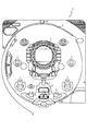
図1は、第1実施例におけるパチンコ遊技機Pの遊技盤の正面図である。遊技盤1の周囲には、打球が入賞することにより5個から15個の遊技球が払い出される複数の入賞口2が設けられている。また、遊技盤1の中央には、複数種類の識別情報としての図柄などを表示する液晶(LCD)ディスプレイ3が設けられている。このLCDディスプレイ3の表示画面は横方向に3分割されており、3分割された各表示領域において、それぞれ図柄の変動表示が行われる。
FIG. 1 is a front view of a game board of a pachinko gaming machine P in the first embodiment. Around the
LCDディスプレイ3の下方には、図柄作動ゲート(第1種始動口)4が設けられ、打球がこの図柄作動ゲート4を通過することにより、前記したLCDディスプレイ3の変動表示が開始される。図柄作動ゲート4の下方には、特定入賞口(大入賞口)5が設けられている。この特定入賞口5は、LCDディスプレイ3の変動後の表示結果が予め定められた図柄の組み合わせの1つと一致する場合に、大当たりとなって、打球が入賞しやすいように所定時間(例えば、30秒経過するまで、あるいは、打球が10個入賞するまで)開放される入賞口である。この特定入賞口5内には、Vゾーン5aが設けられており、特定入賞口5の開放中に、打球がVゾーン5a内を通過すると、継続権が成立して、特定入賞口5の閉鎖後、再度、その特定入賞口5が所定時間(又は、特定入賞口5に打球が所定個数入賞するまで)開放される。この特定入賞口5の開閉動作は、最高で16回(16ラウンド)繰り返し可能にされており、開閉動作の行われ得る状態が、いわゆる所定の遊技価値の付与された状態(特別遊技状態)である。
Below the LCD display 3 is provided a symbol operating gate (first type starting port) 4, and when the hit ball passes through the symbol operating gate 4, the above-described variation display of the LCD display 3 is started. Below the symbol operation gate 4, a specific winning opening (large winning opening) 5 is provided. The specific winning
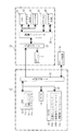
図2は、かかるパチンコ遊技機Pの電気的構成を示したブロック図である。パチンコ遊技機Pの制御部Cは、演算装置であるCPU11と、そのCPU11により実行される各種の制御プログラムや固定値データを記憶したROM12と、各種のデータ等を一時的に記憶するためのメモリであるRAM13とを備えている。図3から図5に示すフローチャートのプログラムは、制御プログラムの一部としてROM12内に記憶されている。
FIG. 2 is a block diagram showing an electrical configuration of the pachinko gaming machine P. As shown in FIG. The control unit C of the pachinko gaming machine P includes a CPU 11 that is an arithmetic device, a
CPU11は、演算を行うALUのほか、アキュームレータ(以下「Acc」と称す)11aや複数の内部レジスタ11b、フラグレジスタ11cを備えている。RAM13内に設けられるカウンタ等の値は、一旦、CPU11の内部レジスタ11bへロードされ(書き込まれ)、その内部レジスタ11b内で更新された後に、RAM13の元のカウンタ内へセイブされて(書き込まれて)、更新される。
The CPU 11 includes an ALU that performs arithmetic operations, an accumulator (hereinafter referred to as “Acc”) 11a, a plurality of internal registers 11b, and a flag register 11c. The values of the counter and the like provided in the
なお、68系の8ビットCPU11では、ペアになっている2バイト(16ビット)の内部レジスタ11bの値を、連続したアドレスの2バイトのメモリ(RAM13内)へ1命令でセイブする(書き込む)ことができる。この場合の書き込みは、バスライン14のデータバスは8ビットで構成されるので、上位バイト、下位バイトの順に行われる。また、80系の8ビットCPUでは、68系のCPU11とは逆に、ペアになっている2バイト(16ビット)の内部レジスタの値を、連続したアドレスの2バイトのメモリへ、下位バイト上位バイトの順に1命令でセイブすることができる。
The 68-system 8-bit CPU 11 saves (writes) the value of the paired 2-byte (16-bit) internal register 11b to the 2-byte memory (in the RAM 13) of consecutive addresses with one instruction. be able to. Writing in this case is performed in the order of the upper byte and the lower byte since the data bus of the
RAM13は、乱数カウンタ13aと、初期値カウンタ13bと、初期値メモリ13cとを備えている。乱数カウンタ13aは、大当たりの発生を決定するためのカウンタであり、図4の乱数更新処理(S7)によって、「0〜630(0〜276h)」の範囲で、2ms毎に1カウントずつ更新される。このため乱数カウンタ13aは2バイトで構成されている。打球が図柄作動ゲート4を通過したときに取得した乱数カウンタ13aの値が例えば「7」であると、大当たりが発生する。大当たりが発生すると、大当たりコマンドが制御部Cから後述する表示装置Dへ送られる。表示装置Dは、この大当たりコマンドに基づいて、LCDディスプレイ3の変動表示を大当たりの状態に制御する。
The
初期値カウンタ13bは、乱数カウンタ13aの更新の初期値をカウントするためのカウンタであり、乱数カウンタ13aと同様に2バイトで構成されている。この初期値カウンタ13bの値は、図5の初期値カウンタ更新処理(S6,S22)によって、乱数カウンタ13aの更新範囲と同じ「0〜630(276h)」の範囲で、1カウントずつ更新される。
The initial value counter 13b is a counter for counting the initial value of the update of the
図5の初期値カウンタ更新処理は、図3のリセット割込処理における残余時間の間、即ち、効果音処理(S20)の終了後、次のリセット割込処理が発生するまでの間に、繰り返し実行される(S22)。リセット割込処理は2ms毎に実行されるが、1回のリセット割込処理において実行されるS1からS20の各処理の処理時間は遊技の状況に応じて変化するので、リセット割込処理の残余時間は、一定な時間ではなく、遊技の状況に応じて変化する不定な時間となる。「ぶら下げ基板」ではこの不定な時間を把握することはできないので、かかる不定な時間内に繰り返し更新される初期値カウンタ13bの値を乱数カウンタ13aの更新の初期値として使用することにより、「ぶら下げ基板」による大当たり発生のタイミングの把握を不可能にしている。
The initial value counter update process of FIG. 5 is repeated during the remaining time in the reset interrupt process of FIG. 3, that is, after the end of the sound effect process (S20) until the next reset interrupt process occurs. It is executed (S22). The reset interrupt process is executed every 2 ms, but the processing time of each process from S1 to S20 executed in one reset interrupt process changes depending on the game situation, so the rest of the reset interrupt process The time is not a fixed time but an indefinite time that changes according to the game situation. Since the “hanging board” cannot grasp the indefinite time, the value of the initial value counter 13b that is repeatedly updated within the indefinite time is used as the initial value for updating the
なお、図5の説明で後述するように、初期値カウンタ13bの値は、CPU11の内部レジスタ11bを介して更新される。内部レジスタ11bから初期値カウンタ13bへの書き込みは68系CPU11の1命令によって、上位バイト、下位バイトの順に行われる。よって、例えば更新前の初期値カウンタ13bの値が「1FFh」の場合、内部レジスタ11b内で「200h」に更新された後に、更新後の値が上位バイト、下位バイトの順に初期値カウンタ13bへ書き込まれる(S45)。即ち、初期値カウンタ13bの値は、「1FFh」の状態から内部レジスタ11bの上位バイトが書き込まれることにより一旦「2FFh」となり、その後、内部レジスタ11bの下位バイトが書き込まれて「200h」に更新されるのである。 As will be described later with reference to FIG. 5, the value of the initial value counter 13b is updated via the internal register 11b of the CPU 11. Writing from the internal register 11b to the initial value counter 13b is performed in the order of upper byte and lower byte by one instruction of the 68-system CPU 11. Therefore, for example, when the value of the initial value counter 13b before the update is “1FFh”, the value after the update is updated to “200h” in the internal register 11b, and then the updated value is transferred to the initial value counter 13b in the order of the upper byte and the lower byte. It is written (S45). That is, the value of the initial value counter 13b is temporarily changed to "2FFh" when the upper byte of the internal register 11b is written from the state of "1FFh", and then the lower byte of the internal register 11b is written and updated to "200h". It is done.
ところが、図5の初期値カウンタ更新処理はリセット割込処理の残余時間の間に繰り返し実行されるので、更新後の内部レジスタ11bの上位バイトを初期値カウンタ13bへ書き込んだ後であって内部レジスタ11bの下位バイトの書き込み前に(S45の処理の途中に)、次のリセット割込処理が発生する場合がある。リセット割込は、割込の発生を禁止することができないノンマスカブルな割込であると共に、割込の優先順位が最も高く、CPU11の命令の実行途中であっても強制的に開始される割込である。よって、かかるタイミングに(更新後の内部レジスタ11bの上位バイトを初期値カウンタ13bへ書き込んだ後であって内部レジスタ11bの下位バイトの書き込み前に)、リセット割込が発生すると、初期値カウンタ13bの値は、本来の更新範囲である「0〜630(0〜276h)」の範囲を超えた「767(2FFh)」になってしまうことがある。 However, since the initial value counter update process of FIG. 5 is repeatedly executed during the remaining time of the reset interrupt process, the upper byte of the updated internal register 11b is written to the initial value counter 13b and the internal register Before the lower byte of 11b is written (during the process of S45), the next reset interrupt process may occur. A reset interrupt is a non-maskable interrupt that cannot inhibit the generation of an interrupt, and has the highest interrupt priority, and is forcibly started even during the execution of an instruction of the CPU 11 It is. Therefore, when a reset interrupt occurs at this timing (after writing the upper byte of the updated internal register 11b to the initial value counter 13b and before writing the lower byte of the internal register 11b), the initial value counter 13b The value of may become “767 (2FFh)” exceeding the range of “0 to 630 (0 to 276h)” which is the original update range.
乱数カウンタ13aの値の更新範囲も「0〜630(0〜276h)」なので、この初期値カウンタ13bの値(767(2FFh))を乱数カウンタ13aの初期値とすると、乱数カウンタ13aの更新周期が変動して大当たりの発生確率を設定値と異なった確率にしてしまったり、或いは、乱数カウンタ13aの更新の初期値を以降は変更できなくしてしまうという不具合が生じる。図4の乱数更新処理(S7)では、乱数カウンタ13aの値は「631(277h)」以上にはなり得ないので(S33:Yes,S34)、一旦、乱数カウンタ13aの更新の範囲外の値である「631(277h)」以上の値が、乱数カウンタ13aの更新の初期値として初期値メモリ13cに書き込まれると(S36,S37)、以降はS35の処理において、Yesの分岐が生じ得ないからである。
Since the update range of the value of the
ここで、初期値カウンタ13bの値が初期値として乱数カウンタ13aへ書き込まれるのは乱数更新処理である(S7のS36〜S38)。一方、本来の更新範囲外の値となった初期値カウンタ13bの値は、図5の初期値カウンタ更新処理を再実行することにより、本来の更新範囲内の値に戻される。「631(277h)」以上の初期値カウンタ13bの値は「0」クリアされるからである(S43:Yes,S44,S45)。よって、本実施例では、上記不具合の発生を回避するために、図5の初期値カウンタ更新処理を、リセット割込処理の残余時間の間に繰り返し実行するだけでなく(S22)、乱数更新処理(S7)の実行前にも少なくとも1回実行している(S6)。
Here, the value of the initial value counter 13b is written as an initial value to the
初期値メモリ13cは、乱数カウンタ13aの更新の初期値を記憶するためのメモリであり、乱数カウンタ13aと同様に2バイトで構成されている。本実施例では、乱数カウンタ13aの更新の初期値は、乱数カウンタの一回りの更新毎に変更される。よって、更新された乱数カウンタ13aの値が初期値メモリ13cの値と一致すると、乱数カウンタ13aの一回りの更新が終了したことになるので、両値13a,13cの一致を契機として、そのときの初期値カウンタ13bの値が乱数カウンタ13aおよび初期値メモリ13cに書き込まれて、乱数カウンタ13aの更新の初期値が変更される。従って、乱数カウンタ13aの更新の初期値を変更しても、乱数の一様性(連続で取得した場合に同じ値を取ることがなく、しかも、すべての値が同じ確率で取り出せること)のある乱数値を得ることができるのである。
The
これらのCPU11、ROM12、RAM13は、バスライン14を介して互いに接続されており、バスライン14は、また、入出力ポート15にも接続されている。この入出力ポート15は表示装置Dや他の入出力装置16と接続されている。制御部Cは、入出力ポート15を介して、表示装置Dや他の入出力装置16へ動作コマンドを送り、それら各装置を制御する。LCDディスプレイ3の変動表示や特定入賞口5の開閉動作も、この動作コマンドに基づいて制御される。
The CPU 11,
表示装置Dは、CPU21と、プログラムROM22と、ワークRAM23と、ビデオRAM24と、キャラクタROM25と、画像コントローラ26と、入出力ポート27と、LCDディスプレイ3とを備えている。表示装置DのCPU21は、制御部Cから出力される動作コマンドに応じて、LCDディスプレイ3の表示制御(変動表示)を行うものであり、プログラムROM22には、このCPU21により実行されるプログラムが記憶されている。ワークRAM23は、CPU21によるプログラムの実行時に使用されるワークデータが記憶されるメモリである。
The display device D includes a
ビデオRAM24は、LCDディスプレイ3に表示されるデータが記憶されるメモリであり、このビデオRAM24の内容を書き換えることにより、LCDディスプレイ3の表示内容が変更される。即ち、各表示領域における図柄の変動表示は、ビデオRAM24の内容が書き換えられることにより行われる。キャラクタROM25は、LCDディスプレイ3に表示される図柄などのキャラクタデータを記憶するメモリである。画像コントローラ26は、CPU21、ビデオRAM24、入出力ポート27のそれぞれのタイミングを調整して、データの読み書きを介在するとともに、ビデオRAM24に記憶される表示データをキャラクタROM25を参照して所定のタイミングでLCDディスプレイ3に表示させるものである。
The
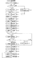
次に、上記のように構成されたパチンコ遊技機Pで実行される各処理を、図3から図5のフローチャートを参照して説明する。図3は、パチンコ遊技機Pの制御部Cにおいて、2ms毎に実行されるリセット割込処理のフローチャートである。パチンコ遊技機Pの主な制御は、このリセット割込処理によって実行される。 Next, each process executed by the pachinko gaming machine P configured as described above will be described with reference to the flowcharts of FIGS. FIG. 3 is a flowchart of reset interrupt processing executed every 2 ms in the control unit C of the pachinko gaming machine P. The main control of the pachinko gaming machine P is executed by this reset interrupt process.
リセット割込処理では、まず、スタックポインタを設定し(S1)、RAM13の所定エリアに書き込まれているパターンのチェックを行う(S2)。チェックの結果、所定エリアに所定のパターンが書き込まれていれば、RAM13に異常はなく正常であるので(S2:正常)、処理をS3へ移行する。一方、S2のチェックの結果、所定エリアに所定のパターンが書き込まれていなければ、電源投入後最初に実行されたリセット割込処理であるか、或いは、RAM13に異常があるので(S2:異常)、この場合には処理をS23へ移行して、一旦、RAM13の内容をクリアした後、RAM13内へ初期値を書き込んで(S23)、次のリセット割込処理の発生を待機する。
In the reset interrupt process, first, a stack pointer is set (S1), and a pattern written in a predetermined area of the
S3の処理ではタイマ割込の設定を行う(S3)。ここで設定されるタイマ割込としては、LCDディスプレイ3の表示を制御するコマンドを表示装置Dへ送信するためのストローブ信号を発生させるタイマ割込などがある。タイマ割込の設定後は、各割込を許可状態とする(S4)。割込の許可後は、特別図柄変動処理(S16)や、表示データ作成処理(S18)、ランプ・情報処理(S19)などにより、前回のリセット割込処理において更新された出力データを一度に各ポートへ出力するポート出力処理を実行する(S5)。その後、後述する初期値カウンタ更新処理(S6)を実行して、初期値カウンタ13bを加算方向へ「+1」更新すると共に、乱数更新処理(S7)を実行して、乱数カウンタ13aの値を「+1」更新し、更に、記憶タイマ減算処理を実行する(S8)。記憶タイマ減算処理は、大当たり判定の保留球が所定数以上あり、且つ、LCDディスプレイ3において図柄の変動表示中である場合に、図柄の変動表示時間の短縮を行うものである。
In the process of S3, a timer interrupt is set (S3). The timer interrupt set here includes a timer interrupt that generates a strobe signal for transmitting a command for controlling the display of the LCD display 3 to the display device D. After setting the timer interrupt, each interrupt is permitted (S4). After the interruption is permitted, the output data updated in the previous reset interruption process is processed at a time by the special symbol variation process (S16), the display data creation process (S18), the ramp / information processing (S19), etc. A port output process for outputting to the port is executed (S5). Thereafter, an initial value counter update process (S6) described later is executed to update the initial value counter 13b by "+1" in the addition direction, and a random number update process (S7) is executed to set the value of the
スイッチ読込処理(S9)は、各スイッチの値を読み込むことにより、遊技領域1へ打ち込まれた打球の入賞口2や大入賞口5(Vゾーン5aを含む)への入賞、図柄作動ゲート4の通過、更には賞球や貸球を検出するための処理である。カウント異常監視処理(S10)は、S9のスイッチ読込処理によって読み込まれたスイッチデータに異常があるか否かを監視するための処理である。例えば、大入賞口5が開放され、打球のVゾーン5aの通過を検出するVカウントスイッチで打球が検出されたにも拘わらず、Vゾーン5a以外の大入賞口5への入賞を検出する10カウントスイッチで1球の打球も検出できない場合には、10カウントスイッチが抜き取られるなどして、10カウントスイッチに何らかの異常が発生している。また、賞球を払い出すモータを駆動したにも拘わらず、1球の賞球も払い出されない場合には、賞球の払出装置に何らかの異常が発生している。このようにカウント異常監視処理(S10)では、スイッチ読込処理(S9)によって読み込まれたスイッチデータに基づいて、上記のような異常の有無を監視している。
In the switch reading process (S9), the value of each switch is read to win the winning ball 2 and the big winning port 5 (including the
図柄カウンタ更新処理(S11)では、LCDディスプレイ3で行われる変動表示の結果、停止表示される図柄を決定するためのカウンタの更新処理が行われる。また、図柄チェック処理(S12)では、図柄カウンタ更新処理(S11)で更新されたカウンタの値に基づいて、特別図柄変動処理(S16)で使用される大当たり図柄や、はずれ図柄、更にはリーチ図柄などが決定される。 In the symbol counter update process (S11), a counter update process for determining a symbol to be stopped and displayed as a result of the variable display performed on the LCD display 3 is performed. Further, in the symbol check process (S12), based on the counter value updated in the symbol counter update process (S11), the jackpot symbol, the off symbol, and the reach symbol used in the special symbol variation process (S16). Etc. are determined.
S3からS12までの処理において、エラーが発生していなければ(S13:正常)、普通図柄変動処理(S14)によって、7セグメントLEDの変動表示を行うと共に、その変動表示の結果、当たりが発生した場合には普通電動役物(図示せず)を所定時間開放する当たり処理を実行する。その後、状態フラグをチェックし(S15)、LCDディスプレイ3の図柄の変動表示中であれば(S15:図柄変動中)、特別図柄変動処理(S16)によって、打球が図柄作動ゲート4を通過するタイミングで読みとられた乱数カウンタ13aの値に基づいて、大当たりか否かの判定が行われると共に、LCDディスプレイ3の表示図柄の変動処理を実行する。一方、状態フラグをチェックした結果、大当たり中であれば(S15:大当り中)、大入賞口5を開放するなどの大当たり処理(S17)を実行する。更に、状態フラグをチェックした結果、図柄の変動中でも大当たり中でもなければ(S15:その他)、S16及びS17の処理をスキップして、S18の表示データ作成処理へ移行する。なお、S13の処理において、エラーが確認された場合には(S13:エラー)、S14〜S17の各処理をスキップして、S18の表示データ作成処理へ移行する。
If no error has occurred in the processing from S3 to S12 (S13: normal), the normal symbol variation processing (S14) displays the variation of the 7-segment LED, and the variation display results in a win. In this case, a hit process for releasing a normal electric accessory (not shown) for a predetermined time is executed. Thereafter, the state flag is checked (S15), and if the symbol variation display on the LCD display 3 is being displayed (S15: symbol variation), the timing at which the hit ball passes the symbol operating gate 4 by the special symbol variation processing (S16). On the basis of the value of the
表示データ作成処理(S18)では、図柄の変動表示以外にLCDディスプレイ3に表示されるデモデータや、7セグメントLEDの表示データなどが作成され、ランプ・情報処理(S19)では、保留球のランプデータをはじめ、各種のランプデータが作成される。効果音処理(S20)では、遊技の状況に応じた効果音データが作成される。なお、これらの表示データおよび効果音データは、前記したポート出力処理(S5)やタイマ割込処理によって各装置へ出力される。 In the display data creation process (S18), demo data displayed on the LCD display 3, display data of the 7 segment LED, and the like are created in addition to the symbol variation display. In the lamp / information processing (S19), the lamp of the holding ball is displayed. Various lamp data including data are created. In the sound effect process (S20), sound effect data corresponding to the game situation is created. These display data and sound effect data are output to each device by the port output process (S5) and the timer interrupt process described above.
効果音処理(S20)の終了後は、次のリセット割込処理が発生するまでの残余時間の間、S11と同一の処理である図柄カウンタ更新処理(S21)と、S6と同一の処理である初期値カウンタ更新処理(S22)とを繰り返し実行する。S1〜S20の各処理の実行時間は遊技の状態に応じて変化するので、次のリセット割込処理が発生するまでの残余時間は、一定の時間ではなく、遊技の状態に応じて変化する。よって、かかる残余時間を使用して図柄カウンタ更新処理(S21)を繰り返し実行することにより、停止図柄をランダムに変更することができる。また、かかる残余時間を使用して初期値カウンタ更新処理(S22)を繰り返し実行することにより、乱数カウンタ13aの更新の初期値となる初期値カウンタ13bの値を「ぶら下げ基板」により把握不可能とすることができる。
After the sound effect processing (S20) ends, during the remaining time until the next reset interrupt processing occurs, the symbol counter update processing (S21), which is the same processing as S11, is the same processing as S6. The initial value counter update process (S22) is repeatedly executed. Since the execution time of each process of S1-S20 changes according to the state of the game, the remaining time until the next reset interrupt process occurs is not a fixed time but changes according to the state of the game. Therefore, by repeatedly executing the symbol counter update process (S21) using the remaining time, the stop symbol can be changed at random. Further, by repeatedly executing the initial value counter updating process (S22) using the remaining time, the value of the initial value counter 13b serving as the initial value of the update of the
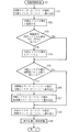
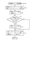
図4は、乱数更新処理のフローチャートである。乱数更新処理(S7)では、CPU11の内部レジスタ11bを介して、乱数カウンタ13aの値を「0〜630(0〜276h)」の範囲内で「+1」ずつ更新すると共に、制御部Cで使用される他の乱数の更新を行っている。
FIG. 4 is a flowchart of random number update processing. In the random number update process (S7), the value of the
まず、2バイトで構成される乱数カウンタ13aの値を2バイトの内部レジスタ11bへ書き込む(S31)。内部レジスタ11bの値を1加算し(S32)、加算後の内部レジスタ11bの値が「631」以上であるか否か、即ち、乱数カウンタ13aの更新範囲の値を超えている否かを調べる(S33)。加算後の内部レジスタ11bの値が「631」以上であれば(S33:Yes)、更新範囲の値を超えているので、内部レジスタ11bの値を「0」クリアする(S34)。一方、加算後の内部レジスタ11bの値が「630」以下であれば(S33:No)、更新範囲内の値であるので、S34の処理をスキップして、S35の処理へ移行する。
First, the value of the
S35の処理では、更新後の内部レジスタ11bの値と初期値メモリ13cの値とが比較される。初期値メモリ13cには乱数カウンタ13aの更新の初期値が記憶されているので、両値が等しい場合には(S35:Yes)、乱数カウンタ13aの更新は一回り終了したということである。よって、かかる場合には、2バイトの初期値カウンタ13bの値を内部レジスタ11bへ書き込み(S36)、その内部レジスタ11bの値を初期値メモリ13c及び乱数カウンタ13aへ書き込んで(S37,S38)、乱数カウンタ13aの更新の初期値を変更する。
In the process of S35, the updated value of the internal register 11b is compared with the value of the
一方、更新後の内部レジスタ11bの値と初期値メモリ13cの値とが等しくない場合には(S35:No)、乱数カウンタ13aの更新は未だ一回り終了していないので、S36及びS37の処理をスキップして、S32からS34の処理で更新された内部レジスタ11bの値を乱数カウンタ13aへ書き込み(S38)、乱数カウンタ13aの更新を行う。その後は、制御部Cで使用される他の乱数の更新処理を行って(S39)、この乱数更新処理を終了する。
On the other hand, when the updated value of the internal register 11b is not equal to the value of the
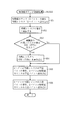
図5は、初期値カウンタ更新処理のフローチャートである。初期値カウンタ更新処理(S6,S22)では、CPU11の内部レジスタ11bを介して、乱数カウンタ13aの更新の初期値をカウントする初期値カウンタ13bの値を、乱数カウンタ13aの更新範囲の「0〜630(0〜276h)」の範囲内で「+1」ずつ更新する。
FIG. 5 is a flowchart of the initial value counter update process. In the initial value counter update processing (S6, S22), the value of the initial value counter 13b that counts the initial value of the update of the
まず、2バイトで構成される初期値カウンタ13bの値を2バイトの内部レジスタ11bへ書き込む(S41)。内部レジスタ11bの値を1加算し(S42)、加算後の内部レジスタ11bの値が「631」以上であるか否か、即ち、乱数カウンタ13aの更新範囲の値を超えている否かを調べる(S43)。加算後の内部レジスタ11bの値が「631」以上であれば(S43:Yes)、乱数カウンタ13aの更新範囲の値を超えているので、内部レジスタ11bの値を「0」クリアする(S44)。一方、加算後の内部レジスタ11bの値が「630」以下であれば(S43:No)、乱数カウンタ13aの更新範囲内の値であるので、S44の処理をスキップして、S45の処理へ移行する。
First, the value of the initial value counter 13b composed of 2 bytes is written to the 2-byte internal register 11b (S41). The value of the internal register 11b is incremented by 1 (S42), and it is checked whether or not the value of the internal register 11b after the addition is “631” or more, that is, whether or not the update range of the
S45の処理では、68系CPU11の2バイト書き込み命令によって、1命令で、2バイトの内部レジスタ11bの値が、上位バイト、下位バイトの順に初期値カウンタ13bへ書き込まれて(S45)、初期値カウンタ13bの更新が行われる。なお、80系CPUでは、更新された2バイトの内部レジスタの値が1バイトずつ、上位バイト、下位バイトの順に2命令で初期値カウンタ13bへ書き込まれる。 In the process of S45, the 2-byte write instruction of the 68-system CPU 11 writes the value of the 2-byte internal register 11b to the initial value counter 13b in the order of the upper byte and the lower byte with one instruction (S45). The counter 13b is updated. In the 80-series CPU, the updated 2-byte internal register value is written to the initial value counter 13b by 2 instructions in order of the upper byte and the lower byte, one byte at a time.
前記した通り、初期値カウンタ更新処理は、リセット割込処理において、次のリセット割込が発生するまでの残余時間の間に繰り返し実行される(S22)。このためS45の処理において、内部レジスタ11bの上位バイトが初期値カウンタ13bへ書き込まれた後であって下位バイトの書き込み前に、次のリセット割込が発生すると、内部レジスタ11bの下位バイトの値を初期値カウンタ13bへ書き込むことなく、図3のS1の処理が実行される。 As described above, the initial value counter update process is repeatedly executed during the remaining time until the next reset interrupt occurs in the reset interrupt process (S22). Therefore, in the process of S45, when the next reset interrupt occurs after the upper byte of the internal register 11b is written to the initial value counter 13b and before the lower byte is written, the value of the lower byte of the internal register 11b 3 is executed without writing to the initial value counter 13b.
例えば、初期値カウンタ13bの値が「1FFh」であれば、S41〜S44の処理によって、内部レジスタ11bの値は「200h」とされる。S45の処理によって、この内部レジスタ11bの上位バイトが初期値カウンタ13bへ書き込まれると、初期値カウンタ13bの値は、一旦「2FFh」となり、乱数カウンタ13aの更新範囲外の値となる。本来ならば、その直後に、内部レジスタ11bの下位バイトが初期値カウンタ13bへ書き込まれ、初期値カウンタ13bの値は「200h」の値になるのだが、前記したように、下位バイトの書き込み前に次のリセット割込が発生すると、下位バイトの書き込みは中止され、初期値カウンタ13bの値は「2FFh」のままになってしまう。
For example, if the value of the initial value counter 13b is “1FFh”, the value of the internal register 11b is set to “200h” by the processing of S41 to S44. When the upper byte of the internal register 11b is written to the initial value counter 13b by the processing of S45, the value of the initial value counter 13b once becomes “2FFh”, which is outside the update range of the
かかる初期値カウンタ13bの値を、乱数更新処理(S7)のS36の処理で使用すると、乱数カウンタ13aの更新の初期値を更新の範囲外の値にしてしまう。しかし、本実施例では、初期値カウンタ更新処理を、乱数更新処理(S7)の前にも実行するようにしているので(S6)、初期値カウンタ13bの値が乱数カウンタ13aの更新範囲外の値となった場合にも、その値を乱数更新処理(S7)の前に、乱数カウンタ13aの更新範囲内の値に戻すことができる。初期値カウンタ更新処理では、「631」以上の値は「0」クリアされるからである(S43:Yes,S44)。よって、乱数カウンタ13aの値を常に所定の更新範囲内で更新することができるのである。
If the value of the initial value counter 13b is used in the process of S36 of the random number update process (S7), the initial value of the update of the
また、本実施例のように、初期値カウンタ更新処理を残余時間のみならず(S22)、乱数更新処理(S7)の前にも実行することにより(S6)、残余時間が不足する場合であっても、初期値カウンタ13bの更新を確実に行うことができるのである。 Further, as in this embodiment, the initial value counter update process is executed not only in the remaining time (S22) but also before the random number update process (S7) (S6), so that the remaining time is insufficient. However, the initial value counter 13b can be reliably updated.
図6は、第2実施例における初期値カウンタ更新処理のフローチャートである。第1実施例の初期値カウンタ更新処理が、初期値カウンタ13bの値を加算方向に「+1」ずつ更新し、且つ、更新後の値を上位バイト下位バイトの順に初期値カウンタ13bへ書き込むのに対し、第2実施例の初期値カウンタ更新処理では、初期値カウンタ13bの値を減算方向に「−1」ずつ更新し、且つ、更新後の値を下位バイト上位バイトの順に初期値カウンタ13bへ書き込んでいる。なお、前記した第1実施例と同一の部分には同一の符号を付し、その説明は省略する。 FIG. 6 is a flowchart of the initial value counter update process in the second embodiment. The initial value counter updating process of the first embodiment updates the value of the initial value counter 13b by “+1” in the addition direction, and writes the updated values to the initial value counter 13b in the order of the upper byte and the lower byte. On the other hand, in the initial value counter update process of the second embodiment, the value of the initial value counter 13b is updated by “−1” in the subtraction direction, and the updated values are transferred to the initial value counter 13b in the order of lower byte and higher byte. I am writing. In addition, the same code | symbol is attached | subjected to the part same as the above-mentioned 1st Example, and the description is abbreviate | omitted.
まず、2バイトで構成される初期値カウンタ13bの値を2バイトの内部レジスタ11bへ書き込む(S51)。内部レジスタ11bの値を1減算し(S52)、減算後の内部レジスタ11bの値が「631(277h)」以上であるか否かを調べる(S53)。減算前の内部レジスタ11bの値が「0」であれば、減算によってその値は「0FFFFh」となる。よって、減算後の内部レジスタ11bの値が「0FFFFh」も含めた「631(277h)」以上であれば(S53:Yes)、乱数カウンタ13aの更新範囲の最大値である「630(276h)」を内部レジスタ11bへ書き込む(S54)。一方、減算後の内部レジスタ11bの値が「630(276h)」以下であれば(S53:No)、S54の処理をスキップして、S55の処理へ移行する。
First, the value of the initial value counter 13b composed of 2 bytes is written to the 2-byte internal register 11b (S51). The value of the internal register 11b is decremented by 1 (S52), and it is checked whether or not the value of the internal register 11b after the subtraction is “631 (277h)” or more (S53). If the value of the internal register 11b before subtraction is “0”, the value becomes “0FFFFh” by subtraction. Therefore, if the value of the internal register 11b after the subtraction is equal to or greater than “631 (277h)” including “0FFFFh” (S53: Yes), “630 (276h)” which is the maximum value of the update range of the
S55の処理では、減算方向に更新された2バイトの内部レジスタ11bの下位バイトの値を2バイトの初期値カウンタ13bの下位バイトへ書き込み(S55)、次に、2バイトの内部レジスタ11bの上位バイトの値を2バイトの初期値カウンタ13bの上位バイトへ書き込む(S56)。即ち、更新された2バイトの内部レジスタ11bの値を1バイトずつ、下位バイト、上位バイトの順に2命令で初期値カウンタ13bへ書き込むのである。なお、80系CPUでは、2バイト書き込み命令によって、1命令で、2バイトの内部レジスタの値を、下位バイト、上位バイトの順に初期値カウンタ13bへ書き込むことができる。 In the process of S55, the lower byte value of the 2-byte internal register 11b updated in the subtraction direction is written to the lower byte of the 2-byte initial value counter 13b (S55), and then the upper byte of the 2-byte internal register 11b. The byte value is written into the upper byte of the 2-byte initial value counter 13b (S56). That is, the updated value of the 2-byte internal register 11b is written to the initial value counter 13b by two instructions in order of the lower byte and the upper byte, one byte at a time. In the 80-series CPU, a 2-byte write instruction can be used to write a 2-byte internal register value to the initial value counter 13b in the order of lower byte and upper byte.
前記した通り、初期値カウンタ更新処理は、リセット割込処理において、次のリセット割込が発生するまでの残余時間の間に繰り返し実行される(S22)。このため、S55の処理によって内部レジスタ11bの下位バイトが初期値カウンタ13bへ書き込まれた後であって、S56の処理による上位バイトの書き込み前に、次のリセット割込が発生する場合がある。リセット割込は、割込の優先順位が最も高く、割込処理の開始を禁止できないノンマスカブルな割込であるので、かかる場合には、S56の処理が行われないまま、初期値カウンタ更新処理が強制終了され、図3のS1の処理が実行される。これにより、書き込み途中の値が更新された初期値カウンタ13bの値になってしまう。 As described above, the initial value counter update process is repeatedly executed during the remaining time until the next reset interrupt occurs in the reset interrupt process (S22). For this reason, the next reset interrupt may occur after the lower byte of the internal register 11b is written to the initial value counter 13b by the process of S55 and before the upper byte is written by the process of S56. Since the reset interrupt has the highest interrupt priority and is a non-maskable interrupt that cannot inhibit the start of the interrupt process, in this case, the initial value counter update process is performed without performing the process of S56. The process is forcibly terminated, and the process of S1 in FIG. 3 is executed. As a result, the value during writing becomes the updated value of the initial value counter 13b.
例えば、初期値カウンタ13bの値が「200h」である場合、S51からS53の処理によって、CPU11の内部レジスタ11bの値は「1FFh」に更新される。更新後の値は、下位バイト上位バイトの順に内部レジスタ11bから初期値カウンタ13bへ書き込まれるので、初期値カウンタ13bの値は下位バイトの書き込みにより一旦「2FFh」となり(S55)、その後、上位バイトの書き込みにより「1FFh」となって(S56)、初期値カウンタ13bの更新が完了する。よって、次のリセット割込が、初期値カウンタ13bの下位バイトへの書き込み後であって上位バイトへの書き込み前に発生すると、初期値カウンタ13bの値は「2FFh」となり、本来の更新範囲の値である「0〜630(0〜276h)」の範囲外の値になってしまう。 For example, when the value of the initial value counter 13b is “200h”, the value of the internal register 11b of the CPU 11 is updated to “1FFh” by the processing from S51 to S53. Since the updated value is written from the internal register 11b to the initial value counter 13b in the order of the lower byte upper byte, the value of the initial value counter 13b once becomes “2FFh” by writing the lower byte (S55), and then the upper byte. Is set to “1FFh” (S56), and the update of the initial value counter 13b is completed. Therefore, if the next reset interrupt occurs after writing to the lower byte of the initial value counter 13b and before writing to the upper byte, the value of the initial value counter 13b becomes “2FFh”, and the original update range The value is out of the range of “0 to 630 (0 to 276h)”.
この初期値カウンタ13bの値を、乱数更新処理(S7)のS36の処理で使用すると、乱数カウンタ13aの更新の初期値を更新の範囲外の値にしてしまう。しかし、本実施例では、初期値カウンタ更新処理を、乱数更新処理(S7)の前にも実行するようにしているので(S6)、初期値カウンタ13bの値が乱数カウンタ13aの更新範囲外の値となった場合にも、その値を乱数更新処理(S7)の前に、乱数カウンタ13aの更新範囲内の値に戻すことができる。初期値カウンタ更新処理では、「631(277h)」以上の値は乱数カウンタ13aの更新範囲の最大値である「630(276h)」に戻されるからである(S53:Yes,S54)。よって、乱数カウンタ13aの値を常に所定の更新範囲内で更新することができる。
If the value of the initial value counter 13b is used in the process of S36 of the random number update process (S7), the initial value of the update of the
なお、上記各実施例において、請求項1記載の定期処理としてはノンマスカブルなリセット割込処理のうちS1からS20の処理が該当し、所定の処理としてはS21及びS22の処理が該当する。第1更新手段としては図4の乱数更新処理(S7)のS31からS34及びS38の処理が該当する。また、第2更新手段としてはS6及びS22の初期値カウンタ更新処理が該当し、変更手段としてはS35からS38の処理が該当する。
In each of the above embodiments, the regular processing according to
以上、実施例に基づき本発明を説明したが、本発明は上記実施例に何ら限定されるものではなく、本発明の趣旨を逸脱しない範囲内で種々の改良変形が可能であることは容易に推察できるものである。 The present invention has been described based on the embodiments. However, the present invention is not limited to the above-described embodiments, and various improvements and modifications can be easily made without departing from the spirit of the present invention. It can be guessed.
例えば、本実施例では、乱数カウンタ13aの更新を行う乱数更新処理(S7)の前に、初期値カウンタ更新処理(S6)を実行して、初期値カウンタ13bの値を乱数カウンタ13aの更新範囲内の値に復帰させていた。しかしながら、必ずしも係る方式に限られるものではなく、例えば、初期値カウンタ13bの値を乱数カウンタ13aおよび初期値メモリ13cへ書き込む前に(S36の処理の前に)、その初期値カウンタ13bの値をチェックして、その値が乱数カウンタ13aの更新範囲外の「631」以上である場合には、初期値カウンタ13bへ「0」または「630」を書き込み、初期値カウンタ13bの値を乱数カウンタ13aの更新範囲内の値に復帰させ、その復帰した値を乱数カウンタ13aおよび初期値メモリ13cへ書き込むようにしても良いのである。
For example, in this embodiment, the initial value counter update process (S6) is executed before the random number update process (S7) for updating the
また、初期値カウンタ13bの値の更新は、その値をCPU11の内部レジスタ11bへ一旦読み込んだ後に行われたが、内部レジスタ11bを介さずに、CPU11内のALUへ直接読み込んで更新するようにしても良い。 The value of the initial value counter 13b is updated after it is once read into the internal register 11b of the CPU 11. However, the initial value counter 13b is read and updated directly into the ALU in the CPU 11 without going through the internal register 11b. May be.
以下に本発明の変形例を示す。請求項1または2に記載の弾球遊技機において、前記復帰手段は前記初期値カウンタの値を前記乱数カウンタの更新の範囲内の値で更新する第3更新手段によって構成されると共に、その第3更新手段は前記第1更新手段の実行前に少なくとも1回実行されることを特徴とする弾球遊技機1。
The modification of this invention is shown below. 3. The bullet ball game machine according to
請求項1記載の弾球遊技機または弾球遊技機1において、前記第2更新手段による更新後の値の前記初期値カウンタへの書き込みは、上位バイト下位バイトの順に2バイトの書き込みが1命令で行われる書き込み命令により実行されることを特徴とする弾球遊技機2。
2. The ball game machine or the
請求項1若しくは2に記載の弾球遊技機または弾球遊技機1若しくは2において、前記初期値カウンタの値は、前記乱数カウンタの値が前記初期値メモリの値と一致する場合に、前記乱数カウンタおよび初期値メモリに書き込まれることを特徴とする弾球遊技機3。
3. The ball game machine or the
11 制御部のCPU
11b 制御部のCPUの内部レジスタ
13 制御部のRAM
13a 乱数カウンタ
13b 初期値カウンタ
13c 初期値メモリ
C 制御部(制御手段)
P パチンコ遊技機(弾球遊技機)
11 CPU of control unit
11b Internal register of CPU of
13a Random number counter 13b
P Pachinko machine ( bullet ball machine)
Claims (2)
前記乱数カウンタの値は、前記第1更新手段により所定回更新されることで一周するものであり、
前記第1更新手段は、前記乱数カウンタの値が一周すると、前記所定の範囲内のいずれかの値を更新の初期値として次の周の更新を行うものであり、
前記制御手段は、
前記乱数カウンタの値が一周する毎に、前記第1更新手段の更新の初期値を変更する変更手段と、
前記所定の範囲と同じ範囲で更新され、前記変更手段が初期値の変更に使用する初期値カウンタと、
その初期値カウンタの値を更新する第2更新手段とを備え、
定期的な割込信号に基づいて定期処理を行うとともに、その定期処理の終了の後、次の定期処理が行われるまでの期間に繰り返し所定の処理を行うものであり、
その所定の処理および前記定期処理において、前記第2更新手段による更新が行われ、
前記第1更新手段による前記乱数カウンタの更新は、前記定期処理において行われ、
電源投入後最初の前記第1更新手段による前記乱数カウンタの更新が行われるより前に、前記第2更新手段による前記初期値カウンタの更新が行われ、
前記所定の処理における前記第2更新手段による前記初期値カウンタの更新が行われた後の前記第1更新手段による前記乱数カウンタの更新が行われる場合であっても、前記定期処理において、前記第1更新手段による前記乱数カウンタの更新が行われるより前に前記第2更新手段による前記初期値カウンタの更新が行われることを特徴とする弾球遊技機。 A random number counter; first update means for updating the value of the random number counter within a predetermined range; and reading means for reading the value of the random number counter based on a predetermined trigger. In the ball game machine provided with a control means for giving a predetermined game value to the player when the value of the random number counter matches a predetermined value,
The value of the random number counter goes around by being updated a predetermined number of times by the first updating means,
When the value of the random number counter makes a round, the first update unit updates the next round using any value within the predetermined range as an initial value of the update,
The control means includes
Change means for changing the initial value of the update of the first update means each time the value of the random number counter goes around,
An initial value counter that is updated in the same range as the predetermined range and used by the changing means to change an initial value;
Second updating means for updating the value of the initial value counter,
Perform periodic processing based on a periodic interrupt signal, and repeatedly perform predetermined processing in the period until the next periodic processing is performed after the end of the periodic processing,
In the predetermined process and the regular process, the update by the second update unit is performed,
The update of the random number counter by the first update means is performed in the regular processing,
The initial value counter is updated by the second update means before the random number counter is updated by the first update means for the first time after power-on,
Even when the random number counter is updated by the first updating unit after the initial value counter is updated by the second updating unit in the predetermined process, The bullet ball game machine, wherein the initial value counter is updated by the second updating means before the random number counter is updated by one updating means.
Priority Applications (1)
| Application Number | Priority Date | Filing Date | Title |
|---|---|---|---|
| JP2007282552A JP4375475B2 (en) | 2007-10-31 | 2007-10-31 | Bullet ball machine |
Applications Claiming Priority (1)
| Application Number | Priority Date | Filing Date | Title |
|---|---|---|---|
| JP2007282552A JP4375475B2 (en) | 2007-10-31 | 2007-10-31 | Bullet ball machine |
Related Parent Applications (1)
| Application Number | Title | Priority Date | Filing Date |
|---|---|---|---|
| JP2006261703A Division JP4293218B2 (en) | 2006-09-27 | 2006-09-27 | Game machine |
Publications (3)
| Publication Number | Publication Date |
|---|---|
| JP2008043799A JP2008043799A (en) | 2008-02-28 |
| JP2008043799A5 JP2008043799A5 (en) | 2009-06-04 |
| JP4375475B2 true JP4375475B2 (en) | 2009-12-02 |
Family
ID=39178049
Family Applications (1)
| Application Number | Title | Priority Date | Filing Date |
|---|---|---|---|
| JP2007282552A Expired - Lifetime JP4375475B2 (en) | 2007-10-31 | 2007-10-31 | Bullet ball machine |
Country Status (1)
| Country | Link |
|---|---|
| JP (1) | JP4375475B2 (en) |
-
2007
- 2007-10-31 JP JP2007282552A patent/JP4375475B2/en not_active Expired - Lifetime
Also Published As
| Publication number | Publication date |
|---|---|
| JP2008043799A (en) | 2008-02-28 |
Similar Documents
| Publication | Publication Date | Title |
|---|---|---|
| JP4033083B2 (en) | Game machine | |
| JP4507019B2 (en) | Bullet ball machine | |
| JP5278501B2 (en) | Bullet ball machine | |
| JP2007190446A (en) | Pinball game machine | |
| JP4407209B2 (en) | Bullet ball machine | |
| JP4375475B2 (en) | Bullet ball machine | |
| JP4375473B2 (en) | Bullet ball machine | |
| JP4375474B2 (en) | Bullet ball machine | |
| JP4124062B2 (en) | Game machine | |
| JP4293218B2 (en) | Game machine | |
| JP2004000755A5 (en) | ||
| JP3951482B2 (en) | Game machine | |
| JP4483847B2 (en) | Game machine | |
| JP4626641B2 (en) | Bullet ball machine | |
| JP4626640B2 (en) | Bullet ball machine | |
| JP4450259B2 (en) | Bullet ball machine | |
| JP4379936B2 (en) | Bullet ball machine | |
| JP4626642B2 (en) | Bullet ball machine | |
| JP4626639B2 (en) | Bullet ball machine | |
| JP4281138B2 (en) | Bullet ball machine | |
| JP5382039B2 (en) | Bullet ball machine | |
| JP5035446B2 (en) | Bullet ball machine | |
| JP4868059B2 (en) | Bullet ball machine | |
| JP2008043797A5 (en) | ||
| JP2008043799A5 (en) |
Legal Events
| Date | Code | Title | Description |
|---|---|---|---|
| A521 | Written amendment |
Free format text: JAPANESE INTERMEDIATE CODE: A523 Effective date: 20090420 |
|
| A871 | Explanation of circumstances concerning accelerated examination |
Free format text: JAPANESE INTERMEDIATE CODE: A871 Effective date: 20090420 |
|
| A975 | Report on accelerated examination |
Free format text: JAPANESE INTERMEDIATE CODE: A971005 Effective date: 20090513 |
|
| A131 | Notification of reasons for refusal |
Free format text: JAPANESE INTERMEDIATE CODE: A131 Effective date: 20090519 |
|
| A521 | Written amendment |
Free format text: JAPANESE INTERMEDIATE CODE: A523 Effective date: 20090721 |
|
| TRDD | Decision of grant or rejection written | ||
| A01 | Written decision to grant a patent or to grant a registration (utility model) |
Free format text: JAPANESE INTERMEDIATE CODE: A01 Effective date: 20090818 |
|
| A01 | Written decision to grant a patent or to grant a registration (utility model) |
Free format text: JAPANESE INTERMEDIATE CODE: A01 |
|
| A61 | First payment of annual fees (during grant procedure) |
Free format text: JAPANESE INTERMEDIATE CODE: A61 Effective date: 20090831 |
|
| R150 | Certificate of patent or registration of utility model |
Free format text: JAPANESE INTERMEDIATE CODE: R150 |
|
| FPAY | Renewal fee payment (event date is renewal date of database) |
Free format text: PAYMENT UNTIL: 20120918 Year of fee payment: 3 |
|
| FPAY | Renewal fee payment (event date is renewal date of database) |
Free format text: PAYMENT UNTIL: 20120918 Year of fee payment: 3 |
|
| FPAY | Renewal fee payment (event date is renewal date of database) |
Free format text: PAYMENT UNTIL: 20150918 Year of fee payment: 6 |
|
| R250 | Receipt of annual fees |
Free format text: JAPANESE INTERMEDIATE CODE: R250 |
|
| R250 | Receipt of annual fees |
Free format text: JAPANESE INTERMEDIATE CODE: R250 |
|
| R250 | Receipt of annual fees |
Free format text: JAPANESE INTERMEDIATE CODE: R250 |
|
| R250 | Receipt of annual fees |
Free format text: JAPANESE INTERMEDIATE CODE: R250 |
|
| EXPY | Cancellation because of completion of term |