JP4374709B2 - Image printing system - Google Patents
Image printing system Download PDFInfo
- Publication number
- JP4374709B2 JP4374709B2 JP2000095770A JP2000095770A JP4374709B2 JP 4374709 B2 JP4374709 B2 JP 4374709B2 JP 2000095770 A JP2000095770 A JP 2000095770A JP 2000095770 A JP2000095770 A JP 2000095770A JP 4374709 B2 JP4374709 B2 JP 4374709B2
- Authority
- JP
- Japan
- Prior art keywords
- image data
- image
- captured
- character
- base station
- Prior art date
- Legal status (The legal status is an assumption and is not a legal conclusion. Google has not performed a legal analysis and makes no representation as to the accuracy of the status listed.)
- Expired - Fee Related
Links
Images


Description
【0001】
【発明の属する技術分野】
本発明は、電子カメラで撮影した画像データを印刷するシステムに係り、特に、電子カメラで撮影した画像データを簡易かつ容易に印刷することができるとともに、撮影の自由度を向上するのに好適な画像印刷システムに関する。
【0002】
【従来の技術】
近年では、ディジタルカメラやディジタルビデオカメラ等のディジタル記録方式の電子カメラが広く普及している。電子カメラは、例えば、CCD(Charge Coupled Device)等からなる撮影部と、撮影部で取り込んだ撮影画像データを記憶する画像メモリとで構成されている。そして、電子カメラで撮影した画像データを印刷するには、一般に、画像メモリに記憶されている撮影画像データをコンピュータに転送し、そのコンピュータに接続されたプリンタにより印刷することにより行う。
【0003】
一方、CCDカメラと、ディスプレイと、画像処理装置と、シール等を印刷するプリンタとを筐体に組み込んで一体化し、CCDカメラで取り込んだ撮影画像データをシール等に印刷して販売するスタンドアロン式の画像印刷物自動販売機(例えば、プリントクラブ(登録商標))も広く知られている。この画像印刷物自動販売機では、利用者が所定の金額を投入して撮影ボタンを操作すると、まず、CCDカメラによる撮影を開始する。そして、CCDカメラで取り込んだ撮影画像データと利用者が選択したフレーム画像データとを合成して、シール等に印刷するようになっている。
【0004】
【発明が解決しようとする課題】
ところで、テーマパーク等のアミューズメント施設では、家族やカップル等が電子カメラを利用して撮影を楽しむという姿がよく見受けられる。しかしながら、従来の画像データを印刷する環境にあっては、電子カメラの他にコンピュータやプリンタ等が必要となり、これら機器をアミューズメント施設に持ち込むのはきわめて困難である。これら機器のすべてを含めると重くなり、持ち運びに不向きだからである。このため、通常は、後日、自宅や会社等で印刷作業を行うことになる。したがって、撮影してから画像を印刷するまでに時間がかかり、見たいときにすぐに印刷することができない。
【0005】
一方、従来の画像印刷物自動販売機は、撮影画像データをその場で直ちにシール等に印刷できるため、アミューズメント施設でも家族やカップル等により利用されている。しかしながら、従来の画像印刷物自動販売機にあっては、撮影部、画像処理部およびプリンタが筐体内に一体化されているため、撮影の自由度が少ないという欠点がある。すなわち、画像印刷物自動販売機の撮影可能な範囲に限定されるため、好みの背景で自由に撮影することができない。
【0006】
そこで、本発明は、このような従来の技術の有する未解決の課題に着目してなされたものであって、電子カメラで撮影した画像データを簡易かつ容易に印刷することができるとともに、撮影の自由度を向上するのに好適な画像印刷システムを提供することを目的としている。
【0007】
【課題を解決するための手段】
上記目的を達成するために、発明1の画像印刷システムは、点在して設置された複数の基地局と、前記各基地局と通信可能に接続する印刷サーバと、前記複数の基地局のうち1または2以上の基地局を介して前記印刷サーバと通信可能に接続する電子カメラとを備えるシステムであって、1又は複数のフレーム画像データを記憶した記憶手段を備え、前記電子カメラで選択されたフレーム画像データを前記記憶手段から読み出し、読み出したフレーム画像データと前記電子カメラで取り込んだ撮影画像データとを合成し、合成した合成画像データを前記印刷サーバで印刷するようになっている。
【0008】
このような構成であれば、電子カメラでフレーム画像データが選択されるとともに撮影画像データが取り込まれると、選択されたフレーム画像データが記憶手段から読み出され、読み出されたフレーム画像データと取り込まれた撮影画像データとが合成され、合成された合成画像データが印刷サーバで印刷される。
【0009】
ここで、フレーム画像データの選択は、電子カメラの利用者に行わせるようにしてもよいし、所定条件に従って行うようにしてもよい。前者の場合は、例えば、利用者がフレーム画像データを選択する選択手段を電子カメラに設け、後者の場合は、例えば、電子カメラの位置や時刻に基づいて決定された条件に従ってフレーム画像データを選択する選択手段を電子カメラに設ける。もちろん、これらを組み合わせた構成であってもよい。
【0010】
また、電子カメラは、画像を取り込むようになっていればどのような構成であってもよく、例えば、画像を静止画として撮影するディジタルカメラ等であってもよいし、画像を動画として撮影するディジタルビデオカメラ等であってもよい。以下、発明2および7の画像印刷システム、発明8ないし11の電子カメラ並びに発明12および13の画像印刷方法において同じである。
【0011】
また、フレーム画像データとは、撮影画像データと重ね合わせるための画像データであって、これには、例えば、漫画やアニメ等のキャラクタを表したキャラクタ画像データ、撮影画像を縁取る枠を表した枠画像データ、自然画等の背景を表した背景画像データが含まれる。以下、発明2の画像印刷システム、発明8ないし11の電子カメラおよび発明12の画像印刷方法において同じである。
【0012】
また、記憶手段は、電子カメラ、基地局または印刷サーバのいずれかに設けられていればよいし、フレーム画像データと撮影画像データとの合成は、電子カメラ、基地局または印刷サーバのいずれかで行うようになっていればよい。これらの組み合わせによる形態は、例えば、次のものが挙げられる。
【0013】
第1に、記憶手段を電子カメラに設け、画像データの合成を電子カメラで行う形態がある。この形態の構成としては、例えば、電子カメラは、選択されたフレーム画像データを記憶手段から読み出し、読み出したフレーム画像データと撮影画像データとを合成し、合成した合成画像データを基地局を介して印刷サーバに送信するようになっている。印刷サーバは、合成画像データを受信したときは、受信した合成画像データを印刷するようになっている。
【0014】
第2に、記憶手段を電子カメラに設け、画像データの合成を印刷サーバで行う形態がある。この形態の構成としては、例えば、電子カメラは、選択されたフレーム画像データを記憶手段から読み出し、読み出したフレーム画像データおよび撮影画像データを基地局を介して印刷サーバに送信するようになっている。印刷サーバは、フレーム画像データおよび撮影画像データを受信したときは、受信したフレーム画像データと受信した撮影画像データとを合成し、合成した合成画像データを印刷するようになっている。
【0015】
第3に、記憶手段を電子カメラに設け、画像データの合成を基地局で行う形態がある。この形態の構成としては、例えば、電子カメラは、選択されたフレーム画像データを記憶手段から読み出し、読み出したフレーム画像データおよび撮影画像データを基地局に送信するようになっている。基地局は、フレーム画像データおよび撮影画像データを受信したときは、受信したフレーム画像データと受信した撮影画像データとを合成し、合成した合成画像データを印刷サーバに送信するようになっている。印刷サーバは、合成画像データを受信したときは、受信した合成画像データを印刷するようになっている。
【0016】
第4に、記憶手段を基地局に設け、画像データの合成を基地局で行う形態がある。この形態の構成としては、例えば、電子カメラは、取り込んだ撮影画像データおよび選択されたフレーム画像データを特定するための画像特定情報を基地局に送信するようになっている。基地局は、撮影画像データおよび画像特定情報を受信したときは、受信した画像特定情報により特定されるフレーム画像データを記憶手段から読み出し、読み出したフレーム画像データと受信した撮影画像データとを合成し、合成した合成画像データを印刷サーバに送信するようになっている。印刷サーバは、受信した合成画像データを印刷するようになっている。
【0017】
第5に、記憶手段を基地局に設け、画像データの合成を電子カメラで行う形態がある。この形態の構成としては、例えば、電子カメラは、選択されたフレーム画像データを特定するための画像特定情報を基地局に送信し、フレーム画像データを受信したときは、受信したフレーム画像データと撮影画像データとを合成し、合成した合成画像データを基地局を介して印刷サーバに送信するようになっている。基地局は、画像特定情報を受信したときは、受信した画像特定情報により特定されるフレーム画像データを記憶手段から読み出し、読み出したフレーム画像データを基地局を介して電子カメラに送信するようになっている。印刷サーバは、合成画像データを受信したときは、受信した合成画像データを印刷するようになっている。
【0018】
第6に、記憶手段を基地局に設け、画像データの合成を印刷サーバで行う形態がある。この形態の構成としては、例えば、電子カメラは、取り込んだ撮影画像データおよび選択されたフレーム画像データを特定するための画像特定情報を基地局に送信するようになっている。基地局は、撮影画像データおよび画像特定情報を受信したときは、受信した画像特定情報により特定されるフレーム画像データを記憶手段から読み出し、読み出したフレーム画像データおよび受信した撮影画像データを印刷サーバに送信するようになっている。印刷サーバは、フレーム画像データおよび撮影画像データを受信したときは、受信したフレーム画像データと受信した撮影画像データとを合成し、合成した合成画像データを印刷するようになっている。
【0019】
第7に、記憶手段を印刷サーバに設け、画像データの合成を印刷サーバで行う形態がある。この形態の構成としては、例えば、電子カメラは、取り込んだ撮影画像データおよび選択されたフレーム画像データを特定するための画像特定情報を基地局を介して印刷サーバに送信するようになっている。印刷サーバは、撮影画像データおよび画像特定情報を受信したときは、受信した画像特定情報により特定されるフレーム画像データを記憶手段から読み出し、読み出したフレーム画像データと受信した撮影画像データとを合成し、合成した合成画像データを印刷するようになっている。
【0020】
第8に、記憶手段を印刷サーバに設け、画像データの合成を電子カメラで行う形態がある。この形態の構成としては、例えば、電子カメラは、選択されたフレーム画像データを特定するための画像特定情報を基地局を介して印刷サーバに送信し、フレーム画像データを受信したときは、受信したフレーム画像データと撮影画像データとを合成し、合成した合成画像データを基地局を介して印刷サーバに送信するようになっている。印刷サーバは、画像特定情報を受信したときは、受信した画像特定情報により特定されるフレーム画像データを記憶手段から読み出し、読み出したフレーム画像データを基地局を介して電子カメラに送信し、合成画像データを受信したときは、受信した合成画像データを印刷するようになっている。
【0021】
第9に、記憶手段を印刷サーバに設け、画像データの合成を基地局で行う形態がある。この形態の構成としては、例えば、電子カメラは、取り込んだ撮影画像データを基地局に送信するとともに、選択されたフレーム画像データを特定するための画像特定情報を基地局を介して印刷サーバに送信するようになっている。基地局は、フレーム画像データおよび撮影画像データを受信したときは、受信したフレーム画像データと受信した撮影画像データとを合成し、合成した合成画像データを印刷サーバに送信するようになっている。印刷サーバは、画像特定情報を受信したときは、受信した画像特定情報により特定されるフレーム画像データを記憶手段から読み出し、読み出したフレーム画像データを基地局に送信し、合成画像データを受信したときは、受信した合成画像データを印刷するようになっている。
【0022】
また、このような形態のうち基地局または印刷サーバに記憶手段を設ける形態において、フレーム画像データの選択を電子カメラの利用者に行わせる場合は、利用者の選択を容易にする観点から、記憶手段の内容と同一のフレーム画像データを記憶するための第2の記憶手段を電子カメラに設けるのが好ましい。これにより、利用者は、電子カメラに表示されるフレーム画像データを見ながらフレーム画像データを選択することができる。なお、第2の記憶手段を設けるに限らず、基地局または印刷サーバからフレーム画像データを取得するようにしてもよい。
【0023】
さらに、発明2の画像印刷システムは、点在して設置された複数の基地局と、前記各基地局と通信可能に接続する印刷サーバと、前記複数の基地局のうち1または2以上の基地局を介して前記印刷サーバと通信可能に接続する電子カメラとを備えるシステムであって、前記電子カメラは、撮影タイミングを入力するスイッチと、画像をデータとして取り込む画像取込手段と、1又は複数のフレーム画像データを記憶するための記憶手段と、前記記憶手段のフレーム画像データのなかからいずれかを選択する選択手段とを有し、前記スイッチの入力タイミングで前記画像取込手段から撮影画像データを取り込み、取り込んだ撮影画像データおよび前記選択手段で選択されたフレーム画像データを特定するための画像特定情報を前記基地局に送信するようになっており、前記印刷サーバは、前記1又は複数のフレーム画像データを記憶した第2の記憶手段と、画像データを印刷する印刷手段とを有し、前記撮影画像データおよび前記画像特定情報を受信したときは、受信した画像特定情報により特定されるフレーム画像データを前記第2の記憶手段から読み出し、読み出したフレーム画像データと前記受信した撮影画像データとを合成して前記印刷手段で印刷するようになっている。
【0024】
このような構成であれば、電子カメラでは、選択手段でフレーム画像データが選択されるとともにスイッチが押下されると、スイッチの入力タイミングで画像取込手段から撮影画像データが取り込まれ、取り込まれた撮影画像データおよび画像特定情報が基地局を介して印刷サーバに送信される。ここで、画像特定情報は、選択されたフレーム画像データを特定するための情報である。
【0025】
印刷サーバでは、撮影画像データおよび画像特定情報を受信すると、受信した画像特定情報により特定されるフレーム画像データが第2の記憶手段から読み出され、読み出されたフレーム画像データと受信した撮影画像データとが合成されて印刷手段で印刷される。
【0026】
ここで、画像取込手段は、画像をデータとして取り込むようになっていればどのような構成であってもよく、例えば、対象によって反射される反射波または対象を透過する透過波を測定することによりその対象の画像を取り込むようになっている。画像取込手段が測定する反射波または透過波には、電波、光、X線その他の電磁波、または超音波その他の音波が含まれる。反射波または透過波の測定は、外界から照射される外界波を利用し、照射される外界波のうち対象によって反射される反射波または対象を透過する透過波を測定することにより行ってもよいし、照射手段により測定波を対象に照射し、照射した測定波のうち対象によって反射される反射波または対象を透過する透過波を測定することにより行ってもよい。前者には、例えば、外界から照射される光を利用し、照射される光のうち対象によって反射される光を測定するカメラが該当し、後者には、例えば、超音波を対象に照射し、照射した超音波のうち対象を透過する超音波を測定する超音波カメラが該当する。以下、発明7の画像印刷システムおよび発明8ないし11の電子カメラにおいて同じである。
【0027】
また、記憶手段は、フレーム画像データをあらゆる手段でかつあらゆる時期に記憶するものであり、フレーム画像データをあらかじめ記憶してあるものであってもよいし、フレーム画像データをあらかじめ記憶することなく、本システムの動作時に与えられる記憶媒体からの読込等によってフレーム画像データを記憶するようになっていてもよい。なお、1のフレーム画像データを記憶する場合は、例えば、本システムの動作中に他のフレーム画像データに書き換えることにより、実質的に複数のフレーム画像データを記憶することもできる。以下、発明9ないし11の電子カメラにおいて同じである。
【0028】
また、選択手段は、フレーム画像データを電子カメラの利用者に選択させるようにしてもよいし、所定条件に従ってフレーム画像データを選択するようにしてもよい。前者の場合は、例えば、利用者がフレーム画像データを選択するセレクトスイッチ等を設け、後者の場合は、例えば、電子カメラの位置や時刻に基づいて決定された条件に従ってフレーム画像データを選択する選択回路等を設ける。もちろん、これらを組み合わせた構成であってもよい。以下、発明8ないし11の電子カメラにおいて同じである。
【0029】
さらに、発明3の画像印刷システムは、発明2の画像印刷システムにおいて、前記電子カメラは、前記撮影画像データの送信を取り消すための取消スイッチを有し、前記画像取込手段から撮影画像データが取り込まれてから所定時間が経過するまでの間に前記取消スイッチが押下されたときは、前記撮影画像データおよび前記画像特定情報の送信を取り消すようになっている。
【0030】
このような構成であれば、電子カメラでは、画像取込手段から撮影画像データが取り込まれてから所定時間が経過するまでの間に取消スイッチが押下されると、撮影画像データおよび画像特定情報の送信が取り消される。
【0031】
さらに、発明4の画像印刷システムは、発明2および3のいずれかの画像印刷システムにおいて、前記電子カメラは、画像を表示する表示手段を有し、前記選択手段で選択されたフレーム画像データと前記撮影画像データとを合成して前記表示手段に表示するようになっている。
【0032】
このような構成であれば、電子カメラでは、選択手段で選択されたフレーム画像データと撮影画像データとが合成されて表示手段に表示される。
【0033】
さらに、発明5の画像印刷システムは、発明2ないし4のいずれかの画像印刷システムにおいて、前記選択手段は、所定条件に従って、前記記憶手段のフレーム画像データのなかからいずれかを選択するようになっている。
【0034】
このような構成であれば、電子カメラでは、選択手段により、所定条件に従って、記憶手段のフレーム画像データのなかからいずれかが選択される。
【0035】
ここで、所定条件に従って選択するとは、例えば、時間、場所その他の要素に基づいて決定される条件に従って選択すること、無作為で選択すること、所定条件が成立したときに選択すること、所定条件が成立したものを選択することをいう。
【0036】
さらに、発明6の画像印刷システムは、発明5の画像印刷システムにおいて、前記選択手段は、当該電子カメラの位置または時刻に基づいて決定された条件に従って、前記記憶手段のフレーム画像データのなかからいずれかを選択するようになっている。
【0037】
このような構成であれば、電子カメラでは、選択手段により、電子カメラの位置または時刻に基づいて決定された条件に従って、記憶手段のフレーム画像データのなかからいずれかが選択される。
【0038】
ここで、電子カメラの位置には、例えば、過去に通過したことのある位置、現在位置、または将来において通過する可能性が高い位置が含まれる。電子カメラの位置の測定は、例えば、電子カメラにおいてGPS(Global Positioning System)を利用するなどして、外部から取得した情報に基づいて行うようになっていてもよいし、ジャイロおよび加速度計を利用するなどして、内部で生成した情報に基づいて行うようになっていてもよいし、基地局または印刷サーバにおいて電子カメラが送受信している基地局に基づいて行うようになっていてもよい。
【0039】
また、時刻には、例えば、過去において所定ポイントを通過したときの時刻、現在時刻、将来において所定ポイントを通過する可能性が高い時刻が含まれる。時刻の測定は、電子カメラ、基地局または印刷サーバにおいて周回衛星を利用するなどして、外部から取得した情報に基づいて行うようになっていてもよいし、クロックタイマを内蔵するなどして、内部で生成した情報に基づいて行うようになっていてもよい。
【0040】
また、所定条件は、電子カメラで決定するのに限らず、電子カメラ、基地局または印刷サーバのいずれかで決定するようになっていればよい。
【0041】
さらに、発明7の画像印刷システムは、アミューズメント施設の敷地内に点在して設置された複数の基地局と、前記各基地局と通信可能に接続する印刷サーバと、前記複数の基地局のうち1または2以上の基地局を介して前記印刷サーバと通信可能に接続する電子カメラとを備えるシステムであって、前記電子カメラは、撮影タイミングを入力するスイッチと、画像をデータとして取り込む画像取込手段とを有し、前記スイッチの入力タイミングで前記画像取込手段から撮影画像データを取り込み、取り込んだ撮影画像データを前記基地局に送信するようになっており、前記印刷サーバは、画像データを印刷する印刷手段を有し、前記撮影画像データを受信したときは、受信した撮影画像データを前記印刷手段で印刷するようになっている。
【0042】
このような構成であれば、電子カメラでは、スイッチが押下されると、スイッチの入力タイミングで画像取込手段から撮影画像データが取り込まれ、取り込まれた撮影画像データが基地局を介して印刷サーバに送信される。
【0043】
印刷サーバでは、撮影画像データを受信すると、受信した撮影画像データが印刷手段で印刷される。
【0044】
一方、上記目的を達成するために、発明8の電子カメラは、撮影タイミングを入力するスイッチと、画像をデータとして取り込む画像取込手段とを備え、前記スイッチの入力タイミングで前記画像取込手段から撮影画像データを取り込む電子カメラにおいて、1又は複数のフレーム画像データのなかからいずれかを選択する選択手段を備え、前記撮影画像データおよび前記選択手段で選択されたフレーム画像データを特定するための画像特定情報を発明1ないし7のいずれかの基地局に送信するようになっている。
【0045】
このような構成であれば、選択手段でフレーム画像データが選択されるとともにスイッチが押下されると、スイッチの入力タイミングで画像取込手段から撮影画像データが取り込まれ、取り込まれた撮影画像データおよび画像特定情報が基地局に送信される。ここで、画像特定情報は、選択されたフレーム画像データを特定するための情報である。
【0046】
さらに、発明9の電子カメラは、撮影タイミングを入力するスイッチと、画像をデータとして取り込む画像取込手段とを備え、前記スイッチの入力タイミングで前記画像取込手段から撮影画像データを取り込む電子カメラにおいて、1又は複数のフレーム画像データを記憶するための記憶手段と、前記記憶手段のフレーム画像データのなかからいずれかを選択する選択手段とを備え、前記撮影画像データおよび前記選択手段で選択されたフレーム画像データを特定するための画像特定情報を発明1ないし7のいずれかの基地局に送信するようになっている。
【0047】
このような構成であれば、選択手段でフレーム画像データが選択されるとともにスイッチが押下されると、スイッチの入力タイミングで画像取込手段から撮影画像データが取り込まれ、取り込まれた撮影画像データおよび画像特定情報が基地局に送信される。ここで、画像特定情報は、選択されたフレーム画像データを特定するための情報である。
【0048】
さらに、発明10の電子カメラは、撮影タイミングを入力するスイッチと、画像をデータとして取り込む画像取込手段とを備え、前記スイッチの入力タイミングで前記画像取込手段から撮影画像データを取り込む電子カメラにおいて、1または複数の画像データを記憶するための記憶手段と、前記記憶手段に記憶された画像データのなかからいずれかを選択することが可能な選択手段とを備え、前記選択手段で前記画像データが選択されたときは、前記撮影画像データを、前記選択手段で選択された画像データを特定するための画像特定情報と対応付けて記憶するようになっている。
【0049】
このような構成であれば、選択手段で画像データが選択されるとともにスイッチが押下されると、スイッチの入力タイミングで画像取込手段から撮影画像データが取り込まれ、取り込まれた撮影画像データが画像特定情報と対応付けられて記憶される。ここで、画像特定情報は、選択された画像データを特定するための情報である。
【0050】
さらに、発明11の電子カメラは、撮影タイミングを入力するスイッチと、画像をデータとして取り込む画像取込手段とを備え、前記スイッチの入力タイミングで前記画像取込手段から撮影画像データを取り込む電子カメラにおいて、1または複数の画像データを記憶するための記憶手段と、前記記憶手段に記憶された画像データのなかからいずれかを選択することが可能な選択手段とを備え、前記選択手段で前記画像データが選択されたときは、前記撮影画像データを、前記選択手段で選択された画像データと合成して記憶するようになっている。
【0051】
このような構成であれば、選択手段で画像データが選択されるとともにスイッチが押下されると、スイッチの入力タイミングで画像取込手段から撮影画像データが取り込まれ、取り込まれた撮影画像データが、選択された画像データと合成されて記憶される。
【0052】
一方、上記目的を達成するために、発明12の画像印刷方法は、アミューズメント施設の敷地内に点在して設置された複数の基地局と、前記各基地局と通信可能に接続する印刷サーバと、前記アミューズメント施設を利用する利用者の利用に供しかつ前記複数の基地局のうち1または2以上の基地局を介して前記印刷サーバと通信可能に接続する電子カメラとを利用して画像を印刷する方法であって、前記電子カメラで画像を撮影するステップと、1又は複数のフレーム画像データのなかからいずれかを選択するステップと、選択したフレーム画像データと前記電子カメラで取り込んだ撮影画像データとを合成するステップと、合成した合成画像データを前記印刷サーバで印刷するステップとを含む。
【0053】
さらに、発明13の画像印刷方法は、アミューズメント施設の敷地内に点在して設置された複数の基地局と、前記各基地局と通信可能に接続する印刷サーバと、前記アミューズメント施設を利用する利用者の利用に供しかつ前記複数の基地局のうち1または2以上の基地局を介して前記印刷サーバと通信可能に接続する電子カメラとを利用して画像を印刷する方法であって、前記電子カメラで画像を撮影するステップと、前記電子カメラで取り込んだ撮影画像データを前記印刷サーバで印刷するステップとを含む。
【0054】
【発明の実施の形態】
以下、本発明の実施の形態を図面を参照しながら説明する。図1ないし図15は、本発明に係る画像印刷システムの実施の形態を示す図である。
【0055】
本実施の形態は、本発明に係る画像印刷システム、電子カメラおよび画像印刷方法を、図1に示すように、テーマパーク等のアミューズメント施設において、利用者にCCDカメラ100を貸与し、利用者がCCDカメラ100を利用して撮影した画像データを印刷サーバ200で印刷し、利用者がCCDカメラ100を返却するのと引き換えに、撮影画像データを印刷したものを利用者に引き渡すという画像印刷サービスを提供する場合に適用したものである。
【0056】
まず、本発明を適用する画像印刷システムの構成を図1を参照しながら説明する。図1は、本発明を適用する画像印刷システムの構成を示す概略図である。
【0057】
この画像印刷システムは、図1に示すように、アミューズメント施設の敷地内10に点在して設置された複数の基地局AP1〜AP7と、各基地局AP1〜AP7と通信可能に接続する印刷サーバ200と、アミューズメント施設を利用する利用者の利用に貸与しかつ1または2以上の基地局APを介して印刷サーバ200と通信可能に接続するCCDカメラ100とで構成されている。
【0058】
各基地局AP1〜AP7は、CCDカメラ100と通信可能な通信エリアCR1〜CR7をそれぞれ有しており、その通信エリア内に存在するCCDカメラ100と無線により通信を行うようになっている。図1の例では、CCDカメラ100は、通信エリアCR 3内および通信エリアCR 6内に存在しているので、基地局AP3および基地局AP6と通信を行う。
【0059】
次に、CCDカメラ100の外観構成を図2を参照しながら詳細に説明する。図2は、CCDカメラ100の背面図である。
【0060】
CCDカメラ100には、図2に示すように、撮影モードを選択するセレクトスイッチSW0〜SW4と、現在の撮影モードをCCDカメラ100の利用者に通知するセレクトランプL0〜L4と、撮影タイミングを入力するレリーズスイッチSW5と、撮影画像データの送信を取り消すためのキャンセルスイッチSW6と、撮影画像を表示するLCD(Liquid Crystal Display)42と、ファインダ44とが設けられている。
【0061】
セレクトスイッチSW0は、漫画やアニメ等のキャラクタを表したキャラクタ画像と合成せずに撮影画像を取り込む第1の撮影モードを指定するスイッチであって、このスイッチを押下したときは、「ノーマル」という文字が記載されたセレクトランプL0が点灯し、現在の撮影モードが第1の撮影モードであることを利用者に通知するようになっている。
【0062】
セレクトスイッチSW1は、第1のキャラクタ画像と合成して撮影画像を取り込む第2の撮影モードを指定するスイッチであって、このスイッチを押下したときは、「キャラクタ1」という文字が記載されたセレクトランプL1が点灯し、現在の撮影モードが第2の撮影モードであることを利用者に通知するようになっている。
【0063】
セレクトスイッチSW2は、第2のキャラクタ画像と合成して撮影画像を取り込む第3の撮影モードを指定するスイッチであって、このスイッチを押下したときは、「キャラクタ2」という文字が記載されたセレクトランプL2が点灯し、現在の撮影モードが第3の撮影モードであることを利用者に通知するようになっている。
【0064】
セレクトスイッチSW3は、第3のキャラクタ画像と合成して撮影画像を取り込む第4の撮影モードを指定するスイッチであって、このスイッチを押下したときは、「キャラクタ3」という文字が記載されたセレクトランプL3が点灯し、現在の撮影モードが第4の撮影モードであることを利用者に通知するようになっている。
【0065】
セレクトスイッチSW4は、CCDカメラ100の現在位置および現在時刻に基づいて選択されたキャラクタ画像と合成して撮影画像を取り込む第5の撮影モードを指定するスイッチであって、このスイッチを押下したときは、「???」という文字が記載されたセレクトランプL4が点灯し、現在の撮影モードが第5の撮影モードであることを利用者に通知するようになっている。
【0066】
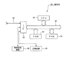
次に、CCDカメラ100の内部構成を図3を参照しながら詳細に説明する。図3は、CCDカメラ100の内部構成を示すブロック図である。
【0067】
CCDカメラ100は、図3に示すように、制御プログラムに基づいて演算およびシステム全体を制御するCPU30と、所定領域にあらかじめCPU30の制御プログラム等を格納しているROM32と、ROM32等から読み出したデータやCPU30の演算過程で必要な演算結果を格納するためのRAM34と、光学レンズ36と、CCD38と、CCD38を制御するCCDコントローラ39と、基地局APと無線により通信を行う無線通信装置40と、LCD42とで構成されており、これらは、データを転送するための信号線であるバスで相互にかつデータ授受可能に接続されている。
【0068】
CPU30には、セレクトスイッチSW0〜SW4と、セレクトランプL0〜L4と、レリーズスイッチSW5と、キャンセルスイッチSW6とが接続されている。
【0069】
CCD38は、複数の画素を有し、前段に配置された光学レンズ36を介して各画素に結像する被写体の光画像を画像信号(電気信号)に光電変換するようになっている。
【0070】
CCDコントローラ39は、図示しないが、DSP(Digital Signal Processor)と、CCD駆動回路と、A/D変換回路と、画像処理部とを有している。画像処理部は、CCD38で光電変換した画像信号を所定タイミングでサンプリングし、サンプリングした信号を所定レベルに増幅するようになっている。A/D変換回路は、画像処理部でサンプリングした画像信号をディジタル化してDSPに供給するようになっている。DSPは、CCD水平駆動パルスをCCD38に供給するとともに、CCD駆動回路を制御することによりCCD垂直駆動パルスをCCD38に供給し、また、A/D変換回路からの撮影画像データをRAM34の所定領域に格納するとともにLCD42に表示するようになっている。
【0071】
次に、RAM34のデータ格納領域を図4を参照しながら詳細に説明する。図4は、RAM34のデータ格納領域を示すメモリマップである。
【0072】
RAM34には、図4に示すように、CCDカメラ100を特定するためのカメラIDを格納した領域340と、撮影画像データと合成するキャラクタ画像データを特定するためのキャラクタコードを格納するためのキャラクタ変数として使用する領域341と、第5の撮影モードにおいて変動的に選択されるキャラクタ画像データを特定するためのキャラクタコードを格納するための変動キャラクタ変数として使用する領域342と、画像バッファB1〜B4に撮影画像データが格納されているか否かを示す画像存在フラグとして使用する領域343〜346と、撮影画像データを格納するための画像バッファB0〜B4と、複数のキャラクタ画像データを格納したキャラクタ画像データ領域DE1〜DEnとが先頭アドレスから順に確保されている。
【0073】
画像バッファB0は、CCDコントローラ39が撮影画像データを格納する領域であって、撮影画像データは、その撮影画像データと合成するキャラクタ画像データのキャラクタコードと対応付けてこの領域に格納される。画像バッファB1〜B4は、CPU30が画像バッファB0の撮影画像データを転送し、基地局APに送信するデータとして格納する領域であって、撮影画像データは、画像バッファB0と同様に、キャラクタコードと対応付けてこの領域に格納される。
【0074】
各キャラクタ画像データ領域DE1〜DEnには、それぞれ異なるキャラクタを表したキャラクタ画像データが格納されている。ここで、キャラクタ画像データ領域DE1のキャラクタ画像データは、第2の撮影モードにおける第1のキャラクタ画像データであり、キャラクタ画像データ領域DE2のキャラクタ画像データは、第3の撮影モードにおける第2のキャラクタ画像データであり、キャラクタ画像データ領域DE3のキャラクタ画像データは、第4の撮影モードにおける第3のキャラクタ画像データである。もちろん、この対応付けは、これに限らず自由に設定できるものである。
【0075】
次に、CPU30の構成およびCPU30で実行される処理を図5ないし図10を参照しながら詳細に説明する。
【0076】
CPU30は、マイクロプロセッシングユニットMPU等からなり、ROM32の所定領域に格納されている所定のプログラムを起動させ、そのプログラムに従って、図5のフローチャートに示す起動処理を実行するようになっている。図5は、起動処理を示すフローチャートである。
【0077】
起動処理は、CCDカメラ100の初期化を行うとともに必要な割込処理を開始する処理であって、CCDカメラ100の起動時にCPU30において実行されると、図5に示すように、まず、ステップS100に移行するようになっている。
【0078】
ステップS100では、CCDカメラ100の初期化を行う初期化処理を実行し、ステップS102に移行して、セレクトスイッチSW0〜SW4が押下されたときに応答するセレクトスイッチ処理を割込処理として実行開始し、ステップS104に移行して、レリーズスイッチSW5が押下されたときに応答するレリーズスイッチ処理を割込処理として実行開始し、ステップS106に移行する。
【0079】
ステップS106では、基地局APとの通信を確立して第5の撮影モードにおいて変動的に選択されるキャラクタ画像データのキャラクタコードをその基地局APから受信する通信確立処理を割込処理として実行開始し、ステップS108に移行して、画像バッファB1〜B4の撮影画像データを基地局APを介して印刷サーバ200に送信する画像転送処理を割込処理として実行開始し、一連の処理を終了する。
【0080】
次に、上記ステップS100の初期化処理を図6を参照しながら詳細に説明する。図6は、初期化処理を示すフローチャートである。
【0081】
初期化処理は、CCDカメラ100の初期化を行う処理であって、CPU30において実行されると、図6に示すように、まず、ステップS200に移行するようになっている。
【0082】
ステップS200では、CCDカメラ100を構成する各ハードウェアに対してリセットをかけ、ステップS202に移行して、すべての画像存在フラグをリセットし、ステップS204に移行して、キャラクタ変数の値をキャラクタコード“0”に設定し、ステップS206に移行して、現在の撮影モードが第1の撮影モードであることを利用者に通知するためにセレクトランプL0を点灯させ、一連の処理を終了して元の処理に復帰させる。
【0083】
次に、上記ステップS102のセレクトスイッチ処理を図7を参照しながら詳細に説明する。図7は、セレクトスイッチ処理を示すフローチャートである。
【0084】
セレクトスイッチ処理は、セレクトスイッチSW0〜SW4が押下されたときに応答する処理であって、CPU30において実行が開始されると、所定周期(例えば、4〔ms〕)ごとに繰り返し実行され、図7に示すように、まず、ステップS300に移行するようになっている。
【0085】
ステップS300では、セレクトスイッチSW0〜SW4のいずれかが押下されたか否かを判定し、セレクトスイッチSW0〜SW4のいずれかが押下されたと判定されたとき(Yes)は、ステップS302に移行する。
【0086】
ステップS302では、押下されたセレクトスイッチがセレクトスイッチSW4であるか否かを判定し、押下されたセレクトスイッチがセレクトスイッチSW4でないと判定されたとき(No)は、ステップS304に移行して、キャラクタ変数の値を、押下されたセレクトスイッチに対応するキャラクタコードに設定する。例えば、セレクトスイッチSW0が押下されたときは、キャラクタ変数の値をキャラクタコード“0”に設定し、同様に、セレクトスイッチSW1〜SW3が押下されたときは、キャラクタ変数の値をキャラクタコード“1”〜“3”に設定する。ここで、キャラクタ変数のキャラクタコードが“0”であることは、撮影画像データをキャラクタ画像データと合成しないこと(すなわち、第1の撮影モードであること)を示す。また、キャラクタ変数のキャラクタコードが“1”〜“3”であることは、撮影画像データをキャラクタ画像データ領域DE1〜DE3のキャラクタ画像データと合成すること(すなわち、第2ないし第4の撮影モードであること)を示す。
【0087】
次いで、ステップS306に移行して、現在の撮影モードが第1ないし第4の撮影モードであることを利用者に通知するために、キャラクタ変数のキャラクタコードに対応するセレクトランプL0〜L3を点灯させる。例えば、セレクトスイッチSW0が押下されたときは、セレクトランプL0を点灯させ、同様に、セレクトスイッチSW1〜SW3が押下されたときは、セレクトランプL1〜L3を点灯させる。
【0088】
次いで、ステップS308に移行して、キャラクタ変数のキャラクタコードに対応するキャラクタ画像をLCD42に表示する。例えば、セレクトスイッチSW1が押下されたときは、キャラクタ画像データ領域DE1からキャラクタ画像データを読み出して表示し、同様に、セレクトスイッチSW2,SW3が押下されたときは、キャラクタ画像データ領域DE2,DE3からキャラクタ画像データを読み出して表示する。また、セレクトスイッチSW4が押下されたときは、キャラクタ変数のキャラクタコードにより特定されるキャラクタ画像データ領域DEからキャラクタ画像データを読み出して表示する。
【0089】
そして、ステップS308の処理が終了すると、一連の処理を終了して元の処理に復帰させる。
【0090】
一方、ステップS302で、押下されたセレクトスイッチがセレクトスイッチSW4であると判定されたとき(Yes)は、ステップS310に移行して、変動キャラクタ変数のキャラクタコードをキャラクタ変数に設定し、ステップS312に移行して、現在の撮影モードが第5の撮影モードであることを利用者に通知するためにセレクトランプL4を点灯させ、ステップS308に移行する。
【0091】
一方、ステップS300で、セレクトスイッチSW0〜SW4のいずれも押下されていないと判定されたとき(No)は、一連の処理を終了して元の処理に復帰させる。
【0092】
次に、上記ステップS104のレリーズスイッチ処理を図8を参照しながら詳細に説明する。図8は、レリーズスイッチ処理を示すフローチャートである。
【0093】
レリーズスイッチ処理は、レリーズスイッチSW5が押下されたときに応答する処理であって、CPU30において実行が開始されると、所定周期(例えば、4〔ms〕)ごとに繰り返し実行され、図8に示すように、まず、ステップS400に移行するようになっている。
【0094】
ステップS400では、レリーズスイッチSW5が押下されたか否かを判定し、レリーズスイッチSW5が押下されたと判定されたとき(Yes)は、ステップS402に移行する。
【0095】
ステップS402では、レリーズスイッチSW5の押下タイミングで撮影画像をCCD38から取り込むようにCCDコントローラ39を制御し、ステップS404に移行して、CCDコントローラ39が画像バッファB0に撮影画像データを格納したことを確認し、キャラクタ変数のキャラクタコードを画像バッファB0の撮影画像データと対応付けて格納し、ステップS406に移行する。
【0096】
ステップS406では、キャラクタ変数のキャラクタコードにより特定されるキャラクタ画像データ領域DEのキャラクタ画像データと画像バッファB0の撮影画像データとをRAM34の所定領域(例えば、VRAMに相当する領域)で合成してLCD42に表示し、ステップS408に移行する。ただし、キャラクタ変数のキャラクタコードが“0”であるときは、撮影画像データをキャラクタ画像データと合成せず、撮影画像データをそのままLCD42に表示する。
【0097】
ステップS408では、キャンセルスイッチSW6が押下されたか否かを判定し、キャンセルスイッチSW6が押下されていないと判定されたとき(No)は、ステップS410に移行して、ステップS408の処理を実行してから所定時間(例えば、5〔s〕)が経過したか否かを判定し、所定時間が経過したと判定されたとき(Yes)は、ステップS412に移行するが、そうでないと判定されたとき(No)は、ステップS408に移行する。
【0098】
ステップS412では、画像存在フラグを参照して、画像バッファB0の撮影画像データおよびキャラクタコードを画像バッファB1〜B4のうち空いているバッファに転送し、ステップS414に移行して、転送先の画像バッファBに対応する画像存在フラグをセットし、一連の処理を終了して元の処理に復帰させる。
【0099】
一方、ステップS408で、キャンセルスイッチSW6が押下されたと判定されたとき(Yes)は、一連の処理を終了して元の処理に復帰させる。
【0100】
一方、ステップS400で、レリーズスイッチSW5が押下されていないと判定されたとき(No)は、一連の処理を終了して元の処理に復帰させる。
【0101】
次に、上記ステップS106の通信確立処理を図9を参照しながら詳細に説明する。図9は、通信確立処理を示すフローチャートである。
【0102】
通信確立処理は、基地局APとの通信を確立して第5の撮影モードにおいて変動的に選択されるキャラクタ画像データのキャラクタコードをその基地局APから受信する処理であって、CPU30において実行が開始されると、所定周期(例えば、4〔ms〕)ごとに繰り返し実行され、図9に示すように、まず、ステップS500に移行するようになっている。
【0103】
ステップS500では、この割込処理の実行を開始してから所定時間(例えば、10〔s〕)が経過したか否かを判定し、所定時間が経過したと判定されたとき(Yes)は、ステップS502に移行するが、そうでないと判定されたとき(No)は、所定時間が経過するまでステップS500で待機する。
【0104】
ステップS502では、カメラIDを基地局APに送信し、ステップS504に移行して、第5の撮影モードにおいて変動的に選択されるキャラクタ画像データのキャラクタコードを送信することを要求するキャラクタコード送信要求を基地局APに送信し、ステップS506に移行する。
【0105】
ステップS506では、キャラクタコードを受信したか否かを判定し、キャラクタコードを受信したと判定されたとき(Yes)は、ステップS508に移行して、受信したキャラクタコードを変動キャラクタ変数に設定し、一連の処理を終了して元の処理に復帰させる。
【0106】
一方、ステップS506で、キャラクタコードを受信していないと判定されたとき(No)は、ステップS510に移行して、ステップS506の処理を実行してから所定時間(例えば、1分)が経過することによりタイムアウトしたか否かを判定し、タイムアウトしたと判定されたとき(Yes)は、キャラクタコードを受信できなかったとしてステップS512に移行するが、そうでないと判定されたとき(No)は、ステップS506に移行する。
【0107】
ステップS512では、変動キャラクタ変数の値をキャラクタコード“0”に設定し、一連の処理を終了して元の処理に復帰させる。
【0108】
次に、上記ステップS108の画像転送処理を図10を参照しながら詳細に説明する。図10は、画像転送処理を示すフローチャートである。
【0109】
画像転送処理は、画像バッファB1〜B4の撮影画像データを基地局APに送信する処理であって、CPU30において実行が開始されると、所定周期(例えば、4〔ms〕)ごとに繰り返し実行され、図10に示すように、まず、ステップS600に移行するようになっている。
【0110】
ステップS600では、この割込処理の実行を開始してから所定時間(例えば、10〔s〕)が経過したか否かを判定し、所定時間が経過したと判定されたとき(Yes)は、ステップS602に移行するが、そうでないと判定されたとき(No)は、所定時間が経過するまでステップS600で待機する。
【0111】
ステップS602では、すべての画像存在フラグがリセットされているか否かを判定し、いずれかの画像存在フラグがセットされていると判定されたとき(No)は、ステップS604に移行して、カメラIDを基地局APに送信し、ステップS606に移行して、撮影画像データを印刷サーバ200に転送することを要求するデータ転送要求を基地局APに送信し、ステップS608に移行する。
【0112】
ステップS608では、画像バッファB1に対応する画像存在フラグがセットされているか否かを判定し、セットされていると判定されたとき(Yes)は、ステップS610に移行して、画像バッファB1の撮影画像データおよびキャラクタコードを基地局APに送信し、一連の処理を終了して元の処理に復帰させる。
【0113】
一方、ステップS608で、画像バッファB1に対応する画像存在フラグがリセットされていると判定されたとき(No)は、ステップS612に移行して、画像バッファB2に対応する画像存在フラグがセットされているか否かを判定し、セットされていると判定されたとき(Yes)は、ステップS614に移行して、画像バッファB2の撮影画像データおよびキャラクタコードを基地局APに送信し、一連の処理を終了して元の処理に復帰させる。
【0114】
一方、ステップS612で、画像バッファB2に対応する画像存在フラグがリセットされていると判定されたとき(No)は、ステップS616に移行して、画像バッファB3に対応する画像存在フラグがセットされているか否かを判定し、セットされていると判定されたとき(Yes)は、ステップS618に移行して、画像バッファB3の撮影画像データおよびキャラクタコードを基地局APに送信し、一連の処理を終了して元の処理に復帰させる。
【0115】
一方、ステップS616で、画像バッファB3に対応する画像存在フラグがリセットされていると判定されたとき(No)は、ステップS620に移行して、画像バッファB4に対応する画像存在フラグがセットされているか否かを判定し、セットされていると判定されたとき(Yes)は、ステップS622に移行して、画像バッファB4の撮影画像データおよびキャラクタコードを基地局APに送信し、一連の処理を終了して元の処理に復帰させる。
【0116】
一方、ステップS602で、すべての画像存在フラグがリセットされていると判定されたとき(Yes)は、一連の処理を終了して元の処理に復帰させる。
【0117】
次に、基地局AP1〜AP7の構成を図11を参照しながら詳細に説明する。図11は、基地局AP1の構成を示すブロック図である。なお、各基地局AP1〜AP7は、いずれも同一機能を有して構成されているので、以下、基地局AP1の構成についてのみ説明し、他のものについては説明を省略する。
【0118】
基地局AP1は、図11に示すように、制御プログラムに基づいて演算およびシステム全体を制御するCPU50と、所定領域にあらかじめCPU50の制御プログラム等を格納しているROM52と、ROM52等から読み出したデータやCPU50の演算過程で必要な演算結果を格納するためのRAM54と、外部装置に対してデータの入出力を媒介するI/F58とで構成されており、これらは、データを転送するための信号線であるバス59で相互にかつデータ授受可能に接続されている。
【0119】
I/F58には、外部装置として、CCDカメラ100と無線により通信を行う無線通信装置60と、データやテーブル等をファイルとして格納する記憶装置62と、印刷サーバ200に接続する信号線64とが接続されている。
【0120】
記憶装置62には、第5の撮影モードのキャラクタコードを設定するためのキャラクタコード設定テーブル110が格納されている。以下、キャラクタコード設定テーブル110のデータ構造を図12を参照しながら詳細に説明する。図12は、キャラクタコード設定テーブル110のデータ構造を示す図である。
【0121】
キャラクタコード設定テーブル110は、所定時間帯ごとにキャラクタコードを設定したテーブルであって、図12に示すように、各時間帯ごとに一つのレコードが登録されている。各レコードは、その時間帯の開始時刻を登録するフィールド112と、その時間帯の終了時刻を登録するフィールド114と、キャラクタコードを登録するフィールド116とを含んで構成されている。
【0122】
図12の例では、図中1段目のレコードには、フィールド112に開始時刻として“10:10”が、フィールド114に終了時刻として“10:30”が、フィールド116にキャラクタコードとして“10”が登録されている。すなわち、図中1段目のレコードは、10:10〜10:30の時間帯において、第5の撮影モードのキャラクタコードをキャラクタコード“10”に設定することを示している。また、図中最下段のレコードには、フィールド112に開始時刻として“17:00”が、フィールド114に終了時刻として“17:10”が、フィールド116にキャラクタコードとして“4”が登録されている。すなわち、図中最下段のレコードは、17:00〜17:10の時間帯において、第5の撮影モードのキャラクタコードをキャラクタコード“4”に設定することを示している。
【0123】
なお、キャラクタコード設定テーブル110の登録内容は、各基地局AP1〜APnごとに異なっている。これにより、CCDカメラ100の現在位置によっては通信する基地局APが異なるため、同じ時間帯でも異なるキャラクタコードが設定されることがある。
【0124】
CPU50は、マイクロプロセッシングユニットMPU等からなり、ROM52の所定領域に格納されている所定のプログラムを起動させ、そのプログラムに従って、図13のフローチャートに示す応答処理を実行するようになっている。図13は、応答処理を示すフローチャートである。
【0125】
応答処理は、CCDカメラ100からのキャラクタコード送信要求およびデータ転送要求に対して応答する処理であって、CPU50において実行されると、図13に示すように、まず、ステップS700に移行するようになっている。
【0126】
ステップS700では、第5の撮影モードのキャラクタコードを変動的に選択するキャラクタコード設定処理を割込処理として実行開始し、ステップS702に移行して、カメラIDを受信したか否かを判定し、カメラIDを受信したと判定されたとき(Yes)は、ステップS704に移行するが、そうでないと判定されたとき(No)は、カメラIDを受信するまでステップS702で待機する。
【0127】
ステップS704では、キャラクタコード送信要求を受信したか否かを判定し、キャラクタコード送信要求を受信したと判定されたとき(Yes)は、ステップS706に移行して、キャラクタ変数のキャラクタコードをカメラIDにより特定されるCCDカメラ100に送信し、ステップS702に移行する。
【0128】
一方、ステップS704で、キャラクタコード送信要求を受信しないと判定されたとき(No)は、ステップS708に移行して、データ転送要求を受信したか否かを判定し、データ転送要求を受信したと判定されたとき(Yes)は、ステップS710に移行して、撮影画像データおよびキャラクタコードを受信し、ステップS712に移行して、受信したカメラID、撮影画像データおよびキャラクタコードを印刷サーバ200に送信し、ステップS702に移行する。
【0129】
一方、ステップS708で、データ転送要求を受信しないと判定されたとき(No)は、ステップS714に移行して、ステップS704の処理を実行してから所定時間(例えば、1分)が経過することによりタイムアウトしたか否かを判定し、タイムアウトしたと判定されたとき(Yes)は、キャラクタコード送信要求またはデータ転送要求を受信できなかったとしてステップS702に移行するが、そうでないと判定されたとき(No)は、ステップS704に移行する。
【0130】
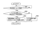
次に、上記ステップS700のキャラクタコード設定処理を図14を参照しながら詳細に説明する。図14は、キャラクタコード設定処理を示すフローチャートである。
【0131】
キャラクタコード設定処理は、第5の撮影モードのキャラクタコードを変動的に選択する処理であって、CPU50において実行されると、図14に示すように、まず、ステップS800に移行するようになっている。
【0132】
ステップS800では、この割込処理の実行を開始してから所定時間(例えば、10〔s〕)が経過したか否かを判定し、所定時間が経過したと判定されたとき(Yes)は、ステップS802に移行するが、そうでないと判定されたとき(No)は、所定時間が経過するまでステップS800で待機する。
【0133】
ステップS802では、キャラクタコード設定テーブル110を参照して、現在時刻がキャラクタコード設定テーブル110に登録されているいずれかの時間帯に属するか否かを判定し、現在時刻がいずれかの時間帯に属すると判定されたとき(Yes)は、ステップS804に移行して、キャラクタコード設定テーブル110のレコードのうち該当する時間帯が登録されているレコードからキャラクタコードを読み出し、読み出したキャラクタコードをキャラクタ変数に設定し、一連の処理を終了して元の処理に復帰させる。
【0134】
一方、ステップS802で、キャラクタコード設定テーブル110を参照して、現在時刻がキャラクタコード設定テーブル110に登録されているいずれの時間帯にも属しないと判定されたとき(No)は、ステップS806に移行して、キャラクタ変数の値をキャラクタコード“0”に設定し、一連の処理を終了して元の処理に復帰させる。
【0135】
次に、印刷サーバ200の構成を図15を参照しながら詳細に説明する。図15は、印刷サーバ200の構成を示すブロック図である。
【0136】
印刷サーバ200は、図15に示すように、制御プログラムに基づいて演算およびシステム全体を制御するCPU70と、所定領域にあらかじめCPU70の制御プログラム等を格納しているROM72と、ROM72等から読み出したデータやCPU70の演算過程で必要な演算結果を格納するためのRAM74と、RAM74の特定領域に格納されているデータを画像信号に変換して表示装置84に出力するCRTC76と、外部装置に対してデータの入出力を媒介するI/F78とで構成されており、これらは、データを転送するための信号線であるバス79で相互にかつデータ授受可能に接続されている。
【0137】
I/F78には、外部装置として、ヒューマンインターフェースとしてデータの入力が可能なキーボードやマウス等からなる入力装置80と、データやテーブル等をファイルとして格納する記憶装置82と、画像信号に基づいて画面を表示する表示装置84と、画像データを紙面等に印刷するプリンタ86と、各基地局AP1〜AP7に接続する信号線88とが接続されている。
【0138】
RAM74は、特定領域として、表示装置84に表示するための表示用データを格納するVRAM75を有しており、VRAM75は、CPU70とCRTC76とで独立にアクセスが可能となっている。
【0139】
CRTC76は、VRAM75に格納されている表示用データを先頭アドレスから所定周期で順次読み出し、読み出した表示用データを画像信号に変換して表示装置84に出力するようになっている。
【0140】
記憶装置82には、CCDカメラ100のRAM34と同一の内容のキャラクタ画像データが格納されている。そして、記憶装置82において各キャラクタ画像データは、CCDカメラ100のキャラクタコードと同一のキャラクタコードによって対応付けられている。
【0141】
CPU70は、マイクロプロセッシングユニットMPU等からなり、ROM72の所定領域に格納されている所定のプログラムを起動させ、そのプログラムに従って、カメラID、撮影画像データおよびキャラクタコードを受信したときは、受信したキャラクタコードにより特定されるキャラクタ画像データを記憶装置82から読み出し、読み出したキャラクタ画像データと受信した撮影画像データとを合成し、合成した合成画像データを表示装置84に表示するとともにプリンタ86で印刷するようになっている。このとき、例えば、特定の利用者が撮影したものであることを識別するために、合成画像データを表面にカメラIDを裏面に印刷する。なお、受信したキャラクタコードが“0”であるときは、撮影画像データをキャラクタ画像データと合成せずに表示または印刷を行う。
【0142】
次に、上記実施の形態の動作を説明する。
【0143】
アミューズメント施設では、入場の際に希望する利用者に対してCCDカメラ100を有償または無償で貸与する。利用者は、アミューズメント施設の敷地内10においてCCDカメラ100により撮影を行うと、撮影画像データが入場口付近に設置されている印刷サーバ200で印刷される。そして、利用者がCCDカメラ100を返却するのと引き換えに、撮影画像データを印刷したものを利用者に引き渡す。アミューズメント施設では、こうした画像印刷サービスが提供される。
【0144】
初めに、利用者が、キャラクタ画像と合成せずに撮影画像を取り込む第1の撮影モードで撮影を行う場合を説明する。
【0145】
第1の撮影モードで撮影を行うには、利用者は、まず、セレクトスイッチSW0を押下し、第1の撮影モードに設定する。
【0146】
CCDカメラ100では、セレクトスイッチSW0が押下されると、ステップS300〜S306を経て、キャラクタ変数の値が“0”に設定され、セレクトランプL0が点灯する。このとき、第1の撮影モードが設定されているので、LCD42には、キャラクタ画像は表示されない。
【0147】
次に、利用者は、レリーズスイッチSW5を押下し、被写体を撮影する。
【0148】
CCDカメラ100では、レリーズスイッチSW5が押下されると、ステップS400,S402を経て、CCDコントローラ39により、レリーズスイッチSW5の押下タイミングで撮影画像がCCD38から取り込まれ、取り込まれた撮影画像データが画像バッファB0に格納される。次いで、ステップS404,S406を経て、キャラクタ変数のキャラクタコード“0”が画像バッファB0の撮影画像データと対応付けられて格納される。このとき、第1の撮影モードが設定されているので、LCD42には、撮影画像がキャラクタ画像と合成されずそのまま表示される。
【0149】
そして、CCD38から撮影画像データが取り込まれてから所定時間が経過すると、ステップS412,S414を経て、画像バッファB0の撮影画像データおよびキャラクタコード“1”が画像バッファB1〜B4のうち空いているバッファに転送される。ここで、画像バッファB1に転送されたとすると、画像バッファB1に対応する画像存在フラグがセットされる。
【0150】
一方、CCDカメラ100では、画像バッファB1に対応する画像存在フラグがセットされると、ステップS600〜S610を経て、カメラIDが基地局AP(例えば、基地局AP3)に送信され、データ転送要求が基地局AP3に送信され、画像バッファB1の撮影画像データおよびキャラクタコード“0”が基地局AP3に送信される。
【0151】
基地局AP3では、カメラIDおよびデータ転送要求を受信すると、ステップS700〜S704,S708〜S712を経て、撮影画像データおよびキャラクタコード“0”を受信し、受信したカメラID、撮影画像データおよびキャラクタコード“0”が印刷サーバ200に送信される。
【0152】
印刷サーバ200では、カメラID、撮影画像データおよびキャラクタコード“0”を受信すると、受信したキャラクタコードが“0”であるので、受信した撮影画像データが合成されずそのままプリンタ86で印刷される。
【0153】
なお、利用者は、例えば、撮影に失敗した等の理由により、撮影画像が印刷サーバ200で印刷されるのを取り消したいときは、レリーズスイッチSW5を押下してから所定時間が経過するまでの間にキャンセルスイッチSW6を押下すればよい。
【0154】
CCDカメラ100では、CCD38から撮影画像データが取り込まれてから所定時間が経過するまでの間にキャンセルスイッチSW6が押下されると、ステップS408を経て、画像バッファB0の撮影画像データおよびキャラクタコードが画像バッファB1〜B4に転送されるのが取り消される。したがって、撮影画像データが印刷サーバ200に送信されることはない。
【0155】
また、利用者が連続して撮影を行うことにより、画像バッファB1〜B4に複数の撮影画像データが格納されたときは、ステップS600〜S622を繰り返し経て、画像バッファB1〜B4の撮影画像データおよびキャラクタコードが所定時間おきに順次基地局AP3に送信される。
【0156】
次に、利用者が、第1のキャラクタ画像と合成して撮影画像を取り込む第2の撮影モードで撮影を行う場合を説明する。
【0157】
第2の撮影モードで撮影を行うには、利用者は、まず、セレクトスイッチSW1を押下し、第2の撮影モードに設定する。
【0158】
CCDカメラ100では、セレクトスイッチSW1が押下されると、ステップS300〜S306を経て、キャラクタ変数の値が“1”に設定され、セレクトランプL1が点灯し、第1のキャラクタ画像がLCD42に表示される。
【0159】
次に、利用者は、LCD42に表示された第1のキャラクタ画像が所望のものであることを確認した上で、レリーズスイッチSW5を押下し、被写体を撮影する。
【0160】
CCDカメラ100では、レリーズスイッチSW5が押下されると、ステップS400,S402を経て、CCDコントローラ39により、レリーズスイッチSW5の押下タイミングで撮影画像がCCD38から取り込まれ、取り込まれた撮影画像データが画像バッファB0に格納される。次いで、ステップS404,S406を経て、キャラクタ変数のキャラクタコード“1”が画像バッファB0の撮影画像データと対応付けられて格納され、キャラクタ画像データ領域DE1のキャラクタ画像データと画像バッファB0の撮影画像データとが合成されてLCD42に表示される。
【0161】
そして、CCD38から撮影画像データが取り込まれてから所定時間が経過すると、ステップS412,S414を経て、画像バッファB0の撮影画像データおよびキャラクタコード“1”が画像バッファB1〜B4のうち空いているバッファに転送される。ここで、画像バッファB2に転送されたとすると、画像バッファB2に対応する画像存在フラグがセットされる。
【0162】
一方、CCDカメラ100では、画像バッファB2に対応する画像存在フラグがセットされると、ステップS600〜S610を経て、カメラIDが基地局AP3に送信され、データ転送要求が基地局AP3に送信され、画像バッファB2の撮影画像データおよびキャラクタコード“1”が基地局AP3に送信される。
【0163】
基地局AP3では、カメラIDおよびデータ転送要求を受信すると、ステップS700〜S704,S708〜S712を経て、撮影画像データおよびキャラクタコード“1”を受信し、受信したカメラID、撮影画像データおよびキャラクタコード“1”が印刷サーバ200に送信される。
【0164】
印刷サーバ200では、カメラID、撮影画像データおよびキャラクタコード“1”を受信すると、受信したキャラクタコード“1”により特定されるキャラクタ画像データが記憶装置82から読み出され、読み出されたキャラクタ画像データと受信した撮影画像データとが合成され、合成された合成画像データがプリンタ86で印刷される。
【0165】
なお、第2の撮影モードで撮影を行う場合にキャンセルスイッチSW6を押下したときも、第1の撮影モードで撮影を行う場合と同様に動作する。
【0166】
また、以上では、第2の撮影モードで撮影を行う場合を説明したが、第3または第4の撮影モードで撮影を行う場合もこれと同じ要領である。
【0167】
次に、利用者が、CCDカメラ100の現在位置および現在時刻に基づいて選択されたキャラクタ画像と合成して撮影画像を取り込む第5の撮影モードで撮影を行う場合を説明する。
【0168】
第5の撮影モードで撮影を行うには、利用者は、まず、セレクトスイッチSW4を押下し、第5の撮影モードに設定する。
【0169】
CCDカメラ100では、セレクトスイッチSW4が押下されるに先だって、ステップS500〜S504を経て、カメラIDが基地局AP3に送信され、キャラクタコード送信要求が基地局AP3に送信される。
【0170】
基地局AP3では、キャラクタコード送信要求を受信するに先立って、ステップS800〜S804を経て、キャラクタコード設定テーブル110を参照してキャラクタ変数の値が設定される。ここで、キャラクタ変数にキャラクタコード“10”が設定されたとする。このように、キャラクタ変数の値が設定された状態で、カメラIDおよびキャラクタコード送信要求を受信すると、ステップS700〜S706を経て、キャラクタ変数のキャラクタコード“10”がCCDカメラ100に送信される。
【0171】
CCDカメラ100では、キャラクタコード送信要求の送信に伴ってキャラクタコード“10”を受信すると、ステップS506,S508を経て、受信したキャラクタコード“10”が変動キャラクタ変数に設定される。このように、変動キャラクタ変数の値が設定された状態で、セレクトスイッチSW4が押下されると、ステップS300〜S306を経て、変動キャラクタ変数のキャラクタコード“10”がキャラクタ変数に設定され、セレクトランプL4が点灯し、キャラクタコード“10”に対応するキャラクタ画像がLCD42に表示される。
【0172】
次に、利用者は、LCD42に表示された第1のキャラクタ画像が所望のものであることを確認した上で、レリーズスイッチSW5を押下し、被写体を撮影する。
【0173】
以下の動作は、第2の撮影モードで撮影を行う場合と同じである。
【0174】
このようにして、本実施の形態では、CCDカメラ100は、レリーズスイッチSW5の押下タイミングでCCD38から撮影画像データを取り込み、取り込んだ撮影画像データを基地局APを介して印刷サーバ200に送信するようにし、印刷サーバ200は、撮影画像データを受信したときは、受信した撮影画像データをプリンタ86で印刷するようにした。
【0175】
これにより、利用者は、撮影してから画像を印刷するまでに時間を要することなく、見たいときにすぐに印刷することができる。したがって、従来に比して、CCDカメラ100で撮影した画像データを比較的簡易かつ容易に印刷することができる。また、アミューズメント施設では、利用者にCCDカメラ100を貸与し、利用者がCCDカメラ100を利用して撮影した画像データを印刷サーバ200で印刷し、利用者がCCDカメラ100を返却するのと引き換えに、撮影画像データを印刷したものを利用者に引き渡すという画像印刷サービスを提供することができる。
【0176】
さらに、本実施の形態では、CCDカメラ100は、レリーズスイッチSW5の押下タイミングでCCD38から撮影画像データを取り込み、取り込んだ撮影画像データおよび選択されたキャラクタコードを基地局APを介して印刷サーバ200に送信するようにし、印刷サーバ200は、撮影画像データおよびキャラクタコードを受信したときは、受信したキャラクタコードにより特定されるキャラクタ画像データを記憶装置82から読み出し、読み出したキャラクタ画像データと受信した撮影画像データとを合成してプリンタ86で印刷するようにした。
【0177】
これにより、利用者は、CCDカメラ100を好みの場所に持ち込んで撮影を行うことができるので、キャラクタ画像との合成撮影を好みの背景もとで行うことができる。したがって、従来に比して、撮影の自由度を比較的向上することができる。
【0178】
さらに、本実施の形態では、CCDカメラ100は、CCD38から撮影画像データが取り込まれてから所定時間が経過するまでの間にキャンセルスイッチSW6が押下されたときは、撮影画像データ及びキャラクタコードの送信を取り消すようにした。
【0179】
これにより、利用者は、撮影に失敗しても、撮影画像が印刷サーバ200で印刷されるのを取り消すことができる。これは、例えば、画像印刷サービスが撮影画像を1枚印刷するごとに所定の料金を支払うという料金体系となっている場合に有利である。利用者は、撮影に失敗しても印刷を取り消せば、料金を支払わなくてすむからである。したがって、画像印刷サービスを提供するにあたって利用者の利便性を向上することができる。
【0180】
さらに、本実施の形態では、CCDカメラ100は、選択されたキャラクタ画像データと撮影画像データとを合成してLCD42に表示するようにした。
【0181】
これにより、利用者は、印刷サーバ200で印刷される合成画像をあらかじめ確認することができる。したがって、画像印刷サービスを提供するにあたって利用者の利便性をさらに向上することができる。
【0182】
さらに、本実施の形態では、CCDカメラ100は、第5の撮影モードが設定されると、CCDカメラ100の現在位置および現在時刻に基づいて決定された条件に従って、キャラクタ画像データを選択するようにした。
【0183】
これにより、利用者は、アミューズメント施設の敷地内10において、場所や時間により変動するキャラクタ画像との合成撮影を楽しむことができる。したがって、満足度の高い画像印刷サービスを提供することができる。
【0184】
上記実施の形態において、キャラクタ画像データは、発明1、2、4、5、6、または8ないし12のフレーム画像データに対応し、キャラクタコードは、発明3、8、9または10の画像特定情報に対応している。
【0185】
また、上記実施の形態において、CCDカメラ100は、発明1ないし4、または6ないし13の電子カメラに対応し、レリーズスイッチSW5は、発明2、または7ないし11のスイッチに対応し、キャンセルスイッチSW6は、発明3の取消スイッチに対応し、CCD38およびCCDコントローラ39は、発明2、3、または7ないし11の画像取込手段に対応している。また、セレクトスイッチSW1〜SW3およびステップS304は、発明2、4、5、6、または8ないし11の選択手段に対応し、セレクトスイッチSW4およびステップS310は、発明5または6の選択手段に対応し、RAM34は、発明2、5、6、9、10または11の記憶手段に対応し、LCD42は、発明4の表示手段に対応している。
【0186】
また、上記実施の形態において、記憶装置82は、発明1の記憶手段または発明2の第2の記憶手段に対応し、プリンタ86は、発明2または7の印刷手段に対応している。
【0187】
なお、上記実施の形態において、図5ないし図10のフローチャートに示す処理を実行するにあたってはいずれも、ROM32にあらかじめ格納されている制御プログラムを実行する場合について説明したが、これに限らず、これらの手順を示したプログラムが記憶された記憶媒体から、そのプログラムをRAM34に読み込んで実行するようにしてもよい。
【0188】
また、上記実施の形態において、図13および図14のフローチャートに示す処理を実行するにあたってはいずれも、ROM52にあらかじめ格納されている制御プログラムを実行する場合について説明したが、これに限らず、これらの手順を示したプログラムが記憶された記憶媒体から、そのプログラムをRAM54に読み込んで実行するようにしてもよい。
【0189】
ここで、記憶媒体とは、RAM、ROM等の半導体記憶媒体、FD、HD等の磁気記憶型記憶媒体、CD、CDV、LD、DVD等の光学的読取方式記憶媒体、MO等の磁気記憶型/光学的読取方式記憶媒体であって、電子的、磁気的、光学的等の読み取り方法のいかんにかかわらず、コンピュータで読み取り可能な記憶媒体であれば、あらゆる記憶媒体を含むものである。
【0190】
また、上記実施の形態においては、本発明に係る画像印刷システム、電子カメラおよび画像印刷方法を、図1に示すように、テーマパーク等のアミューズメント施設において、利用者にCCDカメラ100を貸与し、利用者がCCDカメラ100を利用して撮影した画像データを印刷サーバ200で印刷し、利用者がCCDカメラ100を返却するのと引き換えに、撮影画像データを印刷したものを利用者に引き渡すという画像印刷サービスを提供する場合に適用したが、これに限らず、本発明の主旨を逸脱しない範囲で他の場合にも適用可能である。
【0191】
【発明の効果】
以上説明したように、発明1ないし6の画像印刷システムによれば、撮影してから画像を印刷するまでに時間を要することなく、見たいときにすぐに印刷することができる。また、電子カメラを好みの場所に持ち込んで撮影を行うことができるので、フレーム画像との合成撮影を好みの背景もとで行うことができる。したがって、従来に比して、電子カメラで撮影した画像データを比較的簡易かつ容易に印刷することができるとともに、撮影の自由度を比較的向上することができるという効果が得られる。
【0192】
さらに、発明3の画像印刷システムによれば、撮影に失敗しても、撮影画像が印刷サーバで印刷されるのを取り消すことができる。したがって、画像印刷サービスを提供するにあたって利便性を向上することができるという効果も得られる。
【0193】
さらに、発明4の画像印刷システムによれば、印刷サーバで印刷される合成画像をあらかじめ確認することができる。したがって、画像印刷サービスを提供するにあたって利用者の利便性をさらに向上することができるという効果も得られる。
【0194】
さらに、発明5の画像印刷システムによれば、所定条件により変動するフレーム画像との合成撮影を楽しむことができる。したがって、満足度の高い画像印刷サービスを提供することができるという効果も得られる。
【0195】
さらに、発明6の画像印刷システムによれば、場所や時間により変動するフレーム画像との合成撮影を楽しむことができる。したがって、さらに満足度の高い画像印刷サービスを提供することができるという効果も得られる。
【0196】
さらに、発明7の画像印刷システムによれば、撮影してから画像を印刷するまでに時間を要することなく、見たいときにすぐに印刷することができる。したがって、従来に比して、電子カメラで撮影した画像データを比較的簡易かつ容易に印刷することができるという効果が得られる。また、アミューズメント施設では、利用者に電子カメラを貸与し、利用者が電子カメラを利用して撮影した画像データを印刷サーバで印刷し、利用者が電子カメラを返却するのと引き換えに、撮影画像データを印刷したものを利用者に引き渡すという画像印刷サービスを提供することができるという効果も得られる。
【0197】
一方、発明8または9の電子カメラによれば、発明1または2の画像印刷システムと同等の効果が得られる。
【0198】
さらに、発明10または11の電子カメラによれば、電子カメラを好みの場所に持ち込んで撮影を行うことができるので、フレーム画像との合成撮影を好みの背景もとで行うことができる。したがって、従来に比して、撮影の自由度を比較的向上することができるという効果が得られる。
【0199】
一方、発明12の画像印刷方法によれば、発明1または2の画像印刷システムと同等の効果が得られる。また、アミューズメント施設では、利用者に電子カメラを貸与し、利用者が電子カメラを利用して撮影した画像データを印刷サーバで印刷し、利用者が電子カメラを返却するのと引き換えに、撮影画像データを印刷したものを利用者に引き渡すという画像印刷サービスを提供することができるという効果も得られる。
【0200】
さらに、発明13の画像印刷方法によれば、発明7の画像印刷システムと同等の効果が得られる。
【図面の簡単な説明】
【図1】本発明を適用する画像印刷システムの構成を示す概略図である。
【図2】CCDカメラ100の背面図である。
【図3】CCDカメラ100の内部構成を示すブロック図である。
【図4】RAM34のデータ格納領域を示すメモリマップである。
【図5】起動処理を示すフローチャートである。
【図6】初期化処理を示すフローチャートである。
【図7】セレクトスイッチ処理を示すフローチャートである。
【図8】レリーズスイッチ処理を示すフローチャートである。
【図9】通信確立処理を示すフローチャートである。
【図10】画像転送処理を示すフローチャートである。
【図11】基地局AP1の構成を示すブロック図である。
【図12】キャラクタコード設定テーブル110のデータ構造を示す図である。
【図13】応答処理を示すフローチャートである。
【図14】キャラクタコード設定処理を示すフローチャートである。
【図15】印刷サーバ200の構成を示すブロック図である。
【符号の説明】
100 CCDカメラ
SW0〜SW4 セレクトスイッチ
L0〜L4 セレクトランプ
SW5 レリーズスイッチ
SW6 キャンセルスイッチ
38 CCD
39 CCDコントローラ
42 LCD
AP1〜AP7 基地局
110 キャラクタコード設定テーブル
200 印刷サーバ
30,50,70 CPU
32,52,72 ROM
34,54,74 RAM
75 VRAM
76 CRTC
58,78 I/F
40,60 無線通信装置
80 入力装置
62,82 記憶装置
84 表示装置
86 プリンタ[0001]
BACKGROUND OF THE INVENTION
The present invention is a system for printing image data taken with an electronic camera.ToIn particular, an image printing system that can easily and easily print image data photographed with an electronic camera and that is suitable for improving the degree of freedom of photographing.ToRelated.
[0002]
[Prior art]
In recent years, digital recording type electronic cameras such as digital cameras and digital video cameras have become widespread. The electronic camera includes, for example, a photographing unit made up of a CCD (Charge Coupled Device) and the like, and an image memory that stores photographed image data captured by the photographing unit. In order to print image data captured by an electronic camera, generally, captured image data stored in an image memory is transferred to a computer and printed by a printer connected to the computer.
[0003]
On the other hand, a CCD camera, a display, an image processing device, and a printer that prints stickers and the like are integrated into a housing, and the captured image data captured by the CCD camera is printed on stickers and sold. Image printed material vending machines (for example, Print Club (registered trademark)) are also widely known. In this image printed matter vending machine, when a user inserts a predetermined amount and operates a photographing button, photographing with a CCD camera is first started. The captured image data captured by the CCD camera and the frame image data selected by the user are combined and printed on a sticker or the like.
[0004]
[Problems to be solved by the invention]
By the way, in amusement facilities such as theme parks, it is often seen that families, couples, etc. enjoy taking pictures using an electronic camera. However, in a conventional environment for printing image data, a computer, a printer, and the like are required in addition to an electronic camera, and it is extremely difficult to bring these devices into an amusement facility. If all of these devices are included, they are heavy and unsuitable for carrying. For this reason, usually, printing work is performed later at home or at a company. Therefore, it takes time from shooting to printing an image, and it cannot be printed immediately when it is desired to view it.
[0005]
On the other hand, a conventional image printed matter vending machine can be used to print photographed image data on a sticker or the like immediately on the spot, and is used by families, couples, and the like even in amusement facilities. However, the conventional image printed matter vending machine has a drawback in that the degree of freedom in photographing is small because the photographing unit, the image processing unit, and the printer are integrated in the housing. That is, since it is limited to the range that can be photographed by the image printed matter vending machine, it is not possible to photograph freely with a favorite background.
[0006]
Therefore, the present invention has been made paying attention to such an unsolved problem of the conventional technology, and can easily and easily print image data captured by an electronic camera, Image printing system suitable for improving flexibilityTheIt is intended to provide.
[0007]
[Means for Solving the Problems]
To achieve the above objectiveOf invention 1The image printing system includes a plurality of base stations installed in a scattered manner, a print server that is communicably connected to each of the base stations, and one or more base stations among the plurality of base stations. A system including an electronic camera that is communicably connected to a print server, comprising storage means for storing one or more frame image data, and reading out the frame image data selected by the electronic camera from the storage means; The read frame image data and the captured image data captured by the electronic camera are combined, and the combined image data is printed by the print server.
[0008]
With such a configuration, when frame image data is selected by the electronic camera and photographed image data is captured, the selected frame image data is read from the storage means, and the read frame image data is captured. The combined captured image data is combined, and the combined combined image data is printed by the print server.
[0009]
Here, the selection of the frame image data may be performed by a user of the electronic camera or may be performed according to a predetermined condition. In the former case, for example, the electronic camera is provided with a selection means for the user to select frame image data. In the latter case, for example, the frame image data is selected according to conditions determined based on the position and time of the electronic camera. Selection means for providing the electronic camera is provided. Of course, the structure which combined these may be sufficient.
[0010]
Further, the electronic camera may have any configuration as long as it captures an image. For example, the electronic camera may be a digital camera that captures an image as a still image, or captures an image as a moving image. It may be a digital video camera or the like. Less than,invention2 and7Image printing system,invention8 to 11'sElectronic camera andinvention12 and 1ThreeThe same applies to the image printing method.
[0011]
The frame image data is image data to be superimposed on the photographed image data. For example, the frame image data represents character image data representing a character such as a cartoon or animation, and a frame bordering the photographed image. Frame image data, background image data representing a background such as a natural image, and the like are included. Less than,Invention 2Image printing system,invention8 to 11'sElectronic camera andinvention12The same applies to the image printing method.
[0012]
The storage means may be provided in any one of the electronic camera, the base station, and the print server, and the frame image data and the captured image data are combined in any one of the electronic camera, the base station, or the print server. It only has to be done. Examples of the combination are as follows.
[0013]
First, there is a form in which storage means is provided in an electronic camera and image data is synthesized by the electronic camera. As a configuration of this form, for example, the electronic camera reads the selected frame image data from the storage unit, combines the read frame image data with the captured image data, and combines the combined image data via the base station. It is sent to the print server. When the print server receives the composite image data, the print server prints the received composite image data.
[0014]
Secondly, there is a form in which the storage means is provided in the electronic camera and the image data is synthesized by the print server. As a configuration of this mode, for example, the electronic camera reads selected frame image data from the storage unit, and transmits the read frame image data and captured image data to the print server via the base station. . When receiving the frame image data and the captured image data, the print server combines the received frame image data and the received captured image data, and prints the combined image data.
[0015]
Third, there is a form in which the storage means is provided in the electronic camera and the image data is synthesized at the base station. As a configuration of this form, for example, the electronic camera reads selected frame image data from the storage means, and transmits the read frame image data and captured image data to the base station. When the base station receives the frame image data and the captured image data, the base station combines the received frame image data and the received captured image data, and transmits the combined composite image data to the print server. When the print server receives the composite image data, the print server prints the received composite image data.
[0016]
Fourth, there is a form in which the storage means is provided in the base station and the image data is synthesized in the base station. As a configuration of this form, for example, the electronic camera transmits image capturing information for identifying captured captured image data and selected frame image data to the base station. When receiving the captured image data and the image specifying information, the base station reads out the frame image data specified by the received image specifying information from the storage unit, and combines the read frame image data with the received captured image data. The synthesized composite image data is transmitted to the print server. The print server prints the received composite image data.
[0017]
Fifth, there is a form in which storage means is provided in the base station and image data is synthesized by an electronic camera. As a configuration of this form, for example, when the electronic camera transmits image specifying information for specifying the selected frame image data to the base station and receives the frame image data, the electronic camera captures the received frame image data. The image data is combined with the image data, and the combined image data is transmitted to the print server via the base station. When receiving the image specifying information, the base station reads out the frame image data specified by the received image specifying information from the storage means, and transmits the read frame image data to the electronic camera via the base station. ing. When the print server receives the composite image data, the print server prints the received composite image data.
[0018]
Sixth, there is a form in which the storage means is provided in the base station and the image data is synthesized by the print server. As a configuration of this form, for example, the electronic camera transmits image capturing information for identifying captured captured image data and selected frame image data to the base station. When the base station receives the captured image data and the image specifying information, the base station reads out the frame image data specified by the received image specifying information from the storage unit, and sends the read frame image data and the received captured image data to the print server. It is supposed to send. When receiving the frame image data and the captured image data, the print server combines the received frame image data and the received captured image data, and prints the combined image data.
[0019]
Seventh, there is a form in which the storage means is provided in the print server and the image data is synthesized by the print server. As a configuration of this embodiment, for example, the electronic camera transmits image capture information for capturing captured image data and selected frame image data to a print server via a base station. When the print server receives the captured image data and the image specifying information, the print server reads out the frame image data specified by the received image specifying information from the storage unit, and combines the read frame image data with the received captured image data. The synthesized composite image data is printed.
[0020]
Eighth, there is a form in which the storage means is provided in the print server and the image data is synthesized by the electronic camera. As a configuration of this form, for example, the electronic camera transmits image specifying information for specifying the selected frame image data to the print server via the base station, and receives the frame image data when it is received. The frame image data and the captured image data are combined, and the combined image data is transmitted to the print server via the base station. When the print server receives the image specifying information, the print server reads out the frame image data specified by the received image specifying information from the storage unit, transmits the read frame image data to the electronic camera via the base station, and generates a composite image. When the data is received, the received composite image data is printed.
[0021]
Ninth, there is a form in which the storage means is provided in the print server and the image data is synthesized at the base station. As a configuration of this form, for example, the electronic camera transmits the captured image data captured to the base station, and transmits image specifying information for specifying the selected frame image data to the print server via the base station. It is supposed to be. When the base station receives the frame image data and the captured image data, the base station combines the received frame image data and the received captured image data, and transmits the combined composite image data to the print server. When the print server receives the image specifying information, it reads out the frame image data specified by the received image specifying information from the storage means, transmits the read frame image data to the base station, and receives the composite image data. Prints the received composite image data.
[0022]
Further, in such a form in which the storage unit is provided in the base station or the print server, when the user of the electronic camera performs selection of the frame image data, the storage is performed from the viewpoint of facilitating the user's selection. It is preferable to provide the electronic camera with a second storage means for storing the same frame image data as the contents of the means. Thereby, the user can select the frame image data while viewing the frame image data displayed on the electronic camera. The frame image data may be acquired from the base station or the print server, not limited to the second storage unit.
[0023]
furtherOf invention 2The image printing system includes a plurality of base stations installed in a scattered manner, a print server that is communicably connected to each of the base stations, and one or more base stations among the plurality of base stations. A system including an electronic camera that is communicably connected to a print server, wherein the electronic camera includes a switch that inputs a photographing timing, an image capturing unit that captures an image as data, and one or a plurality of frame image data. Storage means for storing, and selection means for selecting any one of the frame image data of the storage means, and the captured image data is captured and captured from the image capturing means at the input timing of the switch Image specifying information for specifying the captured image data and the frame image data selected by the selecting means is transmitted to the base station. The print server includes a second storage unit that stores the one or more frame image data and a printing unit that prints the image data, and receives the captured image data and the image specifying information. Reads out the frame image data specified by the received image specifying information from the second storage means, combines the read frame image data and the received captured image data, and prints it by the printing means. ing.
[0024]
With such a configuration, in the electronic camera, when the frame image data is selected by the selection unit and the switch is pressed, the captured image data is captured from the image capture unit at the input timing of the switch. The captured image data and the image specifying information are transmitted to the print server via the base station. Here, the image specifying information is information for specifying the selected frame image data.
[0025]
In the print server, when the captured image data and the image specifying information are received, the frame image data specified by the received image specifying information is read from the second storage means, and the read frame image data and the received captured image are received. The data is combined and printed by the printing means.
[0026]
Here, the image capturing means may have any configuration as long as it captures an image as data. For example, it measures a reflected wave reflected by a target or a transmitted wave transmitted through the target. In this way, the target image is captured. The reflected wave or transmitted wave measured by the image capturing means includes radio waves, light, X-rays and other electromagnetic waves, or ultrasonic waves and other sound waves. The measurement of the reflected wave or the transmitted wave may be performed by measuring the reflected wave reflected by the object or the transmitted wave transmitted through the object among the irradiated external waves using the external wave irradiated from the outside. Alternatively, the measurement may be performed by irradiating the object with the measurement wave by the irradiation unit and measuring the reflected wave reflected by the object or the transmitted wave passing through the object among the irradiated measurement waves. For example, the former uses a light irradiated from the outside, and a camera that measures the light reflected by the target among the irradiated light corresponds to the latter, for example, the target is irradiated with an ultrasonic wave, This corresponds to an ultrasonic camera that measures ultrasonic waves that pass through a target among the irradiated ultrasonic waves. Less than,Invention 7Image printing system andinvention8 to 11'sThe same applies to electronic cameras.
[0027]
Further, the storage means stores the frame image data at any time and at any time, and may store the frame image data in advance, or without storing the frame image data in advance, The frame image data may be stored by reading from a storage medium given when the system is operated. When one frame image data is stored, for example, a plurality of frame image data can be substantially stored by rewriting to other frame image data during the operation of the system. Less than,invention9 to 11'sThe same applies to electronic cameras.
[0028]
In addition, the selection unit may cause the user of the electronic camera to select the frame image data, or may select the frame image data according to a predetermined condition. In the former case, for example, a selection switch or the like for the user to select frame image data is provided, and in the latter case, for example, selection for selecting frame image data according to conditions determined based on the position and time of the electronic camera. A circuit is provided. Of course, the structure which combined these may be sufficient. Less than,invention8 to 11'sThe same applies to electronic cameras.
[0029]
furtherOf invention 3The image printing systemInvention 2In the image printing system, the electronic camera has a cancel switch for canceling transmission of the captured image data, and the captured image data is captured from the image capturing unit until a predetermined time elapses. When the cancel switch is pressed, the transmission of the photographed image data and the image specifying information is cancelled.
[0030]
With such a configuration, in the electronic camera, if the cancel switch is pressed during a predetermined time after the captured image data is captured from the image capturing unit, the captured image data and the image specifying information are stored. The transmission is canceled.
[0031]
furtherOf invention 4The
[0032]
With such a configuration, in the electronic camera, the frame image data selected by the selection unit and the captured image data are combined and displayed on the display unit.
[0033]
furtherOf invention 5The image printing systeminventionAny of 2 to 4TheIn the image printing system, the selection unit selects one of the frame image data in the storage unit according to a predetermined condition.
[0034]
With such a configuration, in the electronic camera, any one of the frame image data in the storage unit is selected by the selection unit according to a predetermined condition.
[0035]
Here, selecting according to a predetermined condition is, for example, selecting according to a condition determined based on time, place, or other factors, selecting at random, selecting when a predetermined condition is satisfied, It means to select the one that is established.
[0036]
furtherOf invention 6The image printing systemOf invention 5In the image printing system, the selection unit selects one of the frame image data stored in the storage unit according to a condition determined based on the position or time of the electronic camera.
[0037]
With such a configuration, in the electronic camera, any one of the frame image data in the storage unit is selected by the selection unit according to the condition determined based on the position or time of the electronic camera.
[0038]
Here, the position of the electronic camera includes, for example, a position that has passed in the past, a current position, or a position that is likely to pass in the future. The position of the electronic camera may be measured based on information acquired from the outside, for example, using GPS (Global Positioning System) in the electronic camera, or using a gyroscope and an accelerometer. For example, it may be performed based on internally generated information, or may be performed based on a base station that is transmitted and received by the electronic camera in the base station or the print server.
[0039]
The time includes, for example, the time when a predetermined point was passed in the past, the current time, and the time when there is a high possibility of passing the predetermined point in the future. Time measurement may be based on information acquired from the outside, such as using an orbiting satellite in an electronic camera, base station or print server, or by incorporating a clock timer, It may be based on information generated internally.
[0040]
The predetermined condition is not limited to being determined by the electronic camera, but may be determined by any one of the electronic camera, the base station, and the print server.
[0041]
furtherOf invention 7An image printing system includes: a plurality of base stations scattered and installed in amusement facility sites; a print server that is communicably connected to each of the base stations; and one or more of the plurality of base stations. A system comprising an electronic camera that is communicably connected to the print server via a base station, the electronic camera having a switch for inputting photographing timing and an image capturing means for capturing an image as data The captured image data is captured from the image capturing means at the input timing of the switch, and the captured captured image data is transmitted to the base station. The print server includes a printing means for printing the image data. And when the captured image data is received, the received captured image data is printed by the printing means.
[0042]
With such a configuration, in the electronic camera, when the switch is pressed, the captured image data is captured from the image capturing means at the input timing of the switch, and the captured captured image data is transferred to the print server via the base station. Sent to.
[0043]
When the print server receives the captured image data, the received captured image data is printed by the printing unit.
[0044]
Meanwhile, to achieve the above purposeOf invention 8The electronic camera includes a switch for inputting a photographing timing and an image capturing unit that captures an image as data. In the electronic camera that captures captured image data from the image capturing unit at an input timing of the switch, one or more electronic cameras are provided. Selection means for selecting one of the frame image data, and image specifying information for specifying the captured image data and the frame image data selected by the selection means;inventionAny of 1-7TheIt transmits to the base station.
[0045]
With such a configuration, when the frame image data is selected by the selection unit and the switch is pressed, the captured image data is captured from the image capturing unit at the input timing of the switch, and the captured captured image data and Image identification information is transmitted to the base station. Here, the image specifying information is information for specifying the selected frame image data.
[0046]
furtherOf invention 9The electronic camera includes a switch for inputting a photographing timing and an image capturing unit that captures an image as data. In the electronic camera that captures captured image data from the image capturing unit at an input timing of the switch, one or more electronic cameras are provided. A storage means for storing frame image data; and a selection means for selecting one of the frame image data stored in the storage means; and specifying the captured image data and the frame image data selected by the selection means Image specific information forinventionAny of 1-7TheIt transmits to the base station.
[0047]
With such a configuration, when the frame image data is selected by the selection unit and the switch is pressed, the captured image data is captured from the image capturing unit at the input timing of the switch, and the captured captured image data and Image identification information is transmitted to the base station. Here, the image specifying information is information for specifying the selected frame image data.
[0048]
furtherOf invention 10The electronic camera includes a switch for inputting a photographing timing and an image capturing unit that captures an image as data. In the electronic camera that captures captured image data from the image capturing unit at an input timing of the switch, one or more electronic cameras are provided. A storage means for storing image data; and a selection means capable of selecting any one of the image data stored in the storage means, when the image data is selected by the selection means Stores the captured image data in association with image specifying information for specifying the image data selected by the selection means.
[0049]
With such a configuration, the selection meansPaintingWhen the image data is selected and the switch is pressed, the captured image data is captured from the image capturing means at the input timing of the switch, and the captured captured image data is stored in association with the image specifying information. Here, the image identification information is selectedPictureThis is information for specifying image data.
[0050]
furtherOf invention 11The electronic camera includes a switch for inputting a photographing timing and an image capturing unit that captures an image as data. In the electronic camera that captures captured image data from the image capturing unit at an input timing of the switch, one or more electronic cameras are provided. A storage means for storing image data; and a selection means capable of selecting any one of the image data stored in the storage means, when the image data is selected by the selection means The photographic image data is combined with the image data selected by the selection means and stored.
[0051]
With such a configuration, the selection meansPaintingWhen image data is selected and the switch is pressed, the captured image data is captured from the image capturing means at the input timing of the switch, and the captured captured image data is selected.PictureIt is combined with the image data and stored.
[0052]
Meanwhile, to achieve the above purposeOf invention 12The image printing method is provided for use by a plurality of base stations scattered in the amusement facility site, a print server communicatively connected to each of the base stations, and a user using the amusement facility. A method of printing an image using an electronic camera that is communicably connected to the print server via one or more base stations of the plurality of base stations, the image being taken by the electronic camera A step of selecting one of one or a plurality of frame image data, a step of combining the selected frame image data and the captured image data captured by the electronic camera, and combining the combined image data Printing with the print server.
[0053]
furtherOf invention 13The image printing method is provided for use by a plurality of base stations scattered in the amusement facility site, a print server communicatively connected to each of the base stations, and a user using the amusement facility. A method of printing an image using an electronic camera that is communicably connected to the print server via one or more base stations of the plurality of base stations, the image taking by the electronic camera And a step of printing the photographed image data captured by the electronic camera with the print server.
[0054]
DETAILED DESCRIPTION OF THE INVENTION
Embodiments of the present invention will be described below with reference to the drawings. 1 to 15 show an image printing system according to the present invention.OfIt is a figure which shows embodiment.
[0055]
In the present embodiment, as shown in FIG. 1, the image printing system, the electronic camera, and the image printing method according to the present invention are lent to a user with a
[0056]
First, the configuration of an image printing system to which the present invention is applied will be described with reference to FIG. FIG. 1 is a schematic diagram showing the configuration of an image printing system to which the present invention is applied.
[0057]
As shown in FIG. 1, this image printing system includes a plurality of base stations AP installed in a
[0058]
Each base station AP1~ AP7Is a communication area CR that can communicate with the
[0059]
Next, the external configuration of the
[0060]
As shown in FIG. 2, the
[0061]
Select switch SW0Is a switch for specifying the first shooting mode for capturing a shot image without combining it with a character image representing a character such as a cartoon or an animation. When this switch is pressed, the word “Normal” is written. Select lamp L0Is turned on to notify the user that the current shooting mode is the first shooting mode.
[0062]
Select switch SW1Is a switch for designating a second shooting mode in which a shot image is captured by being combined with the first character image. When this switch is pressed, a select lamp L on which the characters “
[0063]
Select switch SW2Is a switch for designating a third shooting mode for capturing a shot image by combining with the second character image, and when this switch is pressed, a select lamp L on which the characters “
[0064]
Select switch SWThreeIs a switch for designating a fourth shooting mode for synthesizing with the third character image and capturing the shot image. When this switch is pressed, a select lamp L on which the characters “
[0065]
Select switch SWFourIs a switch for designating a fifth shooting mode for capturing a shot image by combining with a character image selected based on the current position and the current time of the
[0066]
Next, the internal configuration of the
[0067]
As shown in FIG. 3, the
[0068]
The
[0069]
The
[0070]
Although not shown, the
[0071]
Next, the data storage area of the
[0072]
As shown in FIG. 4, the
[0073]
Image buffer B0Is an area where the
[0074]
Each character image data area DE1~ DEnStores character image data representing different characters. Here, the character image data area DE1Character image data is first character image data in the second shooting mode, and is a character image data area DE.2Character image data is second character image data in the third shooting mode, and character image data area DEThreeIs the third character image data in the fourth shooting mode. Of course, this association is not limited to this and can be freely set.
[0075]
Next, the configuration of the
[0076]
The
[0077]
The start-up process is a process for initializing the
[0078]
In step S100, an initialization process for initializing the
[0079]
In step S106, communication with the base station AP is established, and communication establishment processing for receiving the character code of character image data variably selected in the fifth shooting mode from the base station AP is started as interrupt processing. Then, the process proceeds to step S108 and the image buffer B1~ BFourThe image transfer process for transmitting the captured image data to the
[0080]
Next, the initialization process in step S100 will be described in detail with reference to FIG. FIG. 6 is a flowchart showing the initialization process.
[0081]
The initialization process is a process for initializing the
[0082]
In step S200, each hardware constituting the
[0083]
Next, the select switch process in step S102 will be described in detail with reference to FIG. FIG. 7 is a flowchart showing the select switch process.
[0084]
Select switch processing is select switch SW0~ SWFourIs a process that responds when is pressed, and when execution is started in the
[0085]
In step S300, the select switch SW0~ SWFourIt is determined whether any of the buttons is pressed, and the select switch SW0~ SWFourWhen it is determined that any of the above has been pressed (Yes), the process proceeds to step S302.
[0086]
In step S302, the selected switch that has been pressed is selected by the select switch SW.FourIt is determined whether or not the selected switch is the select switch SW.FourIf it is determined that it is not (No), the process proceeds to step S304, and the value of the character variable is set to the character code corresponding to the pressed select switch. For example, select switch SW0When is pressed, the value of the character variable is set to the character code “0” and, similarly, the select switch SW1~ SWThreeWhen is pressed, the value of the character variable is set to character codes “1” to “3”. Here, the character code of the character variable being “0” indicates that the photographed image data is not combined with the character image data (that is, the first photographing mode). In addition, the character code of the character variable being “1” to “3” indicates that the captured image data is represented in the character image data area DE.1~ DEThreeIs combined with the character image data (that is, the second to fourth shooting modes).
[0087]
Next, the process proceeds to step S306, and the select lamp L corresponding to the character code of the character variable is used to notify the user that the current shooting mode is the first to fourth shooting modes.0~ LThreeLights up. For example, select switch SW0When is pressed, select lamp L0In the same way, select switch SW1~ SWThreeWhen is pressed, select lamp L1~ LThreeLights up.
[0088]
Next, the process proceeds to step S308, and a character image corresponding to the character code of the character variable is displayed on the LCD. For example, select switch SW1When is pressed, the character image data area DE1Character image data is read out from the image and displayed. Similarly, the select switch SW2, SWThreeWhen is pressed, the character image data area DE2, DEThreeThe character image data is read out from and displayed. Select switch SWFourWhen is pressed, character image data is read from the character image data area DE specified by the character code of the character variable and displayed.
[0089]
Then, when the process of step S308 ends, the series of processes ends and the original process is restored.
[0090]
On the other hand, in step S302, the select switch that is pressed down is the select switch SW.FourIf it is determined (Yes), the process proceeds to step S310, the character code of the variable character variable is set as the character variable, the process proceeds to step S312, and the current shooting mode is the fifth shooting mode. Select lamp L to notify the user that there isFourIs turned on, and the process proceeds to step S308.
[0091]
On the other hand, in step S300, the select switch SW0~ SWFourWhen it is determined that none of the buttons is pressed (No), the series of processes is terminated and the original process is restored.
[0092]
Next, the release switch process in step S104 will be described in detail with reference to FIG. FIG. 8 is a flowchart showing the release switch process.
[0093]
Release switch processing is the release switch SW.FiveIs a process that responds when the button is pressed, and when the
[0094]
In step S400, the release switch SWFiveWhether or not the release switch SWFiveWhen it is determined that is pressed (Yes), the process proceeds to step S402.
[0095]
In step S402, the release switch SWFiveThe
[0096]
In step S406, the character image data in the character image data area DE specified by the character code of the character variable and the image buffer B0Are combined in a predetermined area (for example, an area corresponding to VRAM) of the
[0097]
In step S408, the cancel switch SW6To determine whether or not the cancel switch SW6When it is determined that is not pressed (No), the process proceeds to step S410, and it is determined whether or not a predetermined time (for example, 5 [s]) has elapsed since execution of the process of step S408. When it is determined that the predetermined time has elapsed (Yes), the process proceeds to step S412. When it is determined that this is not the case (No), the process proceeds to step S408.
[0098]
In step S412, the image buffer B is referred to by referring to the image presence flag.0Captured image data and character code of the image buffer B1~ BFourAre transferred to an empty buffer, and the process proceeds to step S414 to set an image presence flag corresponding to the transfer destination image buffer B, and a series of processes is terminated to return to the original process.
[0099]
On the other hand, in step S408, the cancel switch SW6When it is determined that is pressed (Yes), the series of processing is terminated and the original processing is restored.
[0100]
On the other hand, in step S400, the release switch SW.FiveWhen it is determined that is not pressed (No), the series of processes is terminated and the process returns to the original process.
[0101]
Next, the communication establishment process in step S106 will be described in detail with reference to FIG. FIG. 9 is a flowchart showing communication establishment processing.
[0102]
The communication establishment process is a process of establishing the communication with the base station AP and receiving the character code of the character image data variably selected in the fifth shooting mode from the base station AP. When started, it is repeatedly executed every predetermined period (for example, 4 [ms]), and as shown in FIG. 9, first, the process proceeds to step S500.
[0103]
In step S500, it is determined whether or not a predetermined time (for example, 10 [s]) has elapsed since the start of the execution of the interrupt process. When it is determined that the predetermined time has elapsed (Yes), The process proceeds to step S502. If it is determined that this is not the case (No), the process waits in step S500 until a predetermined time has elapsed.
[0104]
In step S502, the camera ID is transmitted to the base station AP, and the process proceeds to step S504 to request transmission of a character code of character image data that is variably selected in the fifth shooting mode. Is transmitted to the base station AP, and the process proceeds to step S506.
[0105]
In step S506, it is determined whether or not a character code has been received. If it is determined that a character code has been received (Yes), the process proceeds to step S508, where the received character code is set as a variable character variable. A series of processing is terminated and the original processing is restored.
[0106]
On the other hand, when it is determined in step S506 that no character code has been received (No), the process proceeds to step S510, and a predetermined time (for example, 1 minute) elapses after the process of step S506 is executed. It is determined whether or not a timeout has occurred, and if it is determined that the timeout has occurred (Yes), the process proceeds to step S512 because the character code has not been received, but if it is not determined (No), The process proceeds to step S506.
[0107]
In step S512, the value of the variable character variable is set to the character code “0”, the series of processes is terminated, and the original process is restored.
[0108]
Next, the image transfer process in step S108 will be described in detail with reference to FIG. FIG. 10 is a flowchart showing the image transfer process.
[0109]
Image transfer processing is performed by image buffer B1~ BFourThe captured image data is transmitted to the base station AP. When the
[0110]
In step S600, it is determined whether or not a predetermined time (for example, 10 [s]) has elapsed since the start of execution of this interrupt process. If it is determined that the predetermined time has elapsed (Yes), The process proceeds to step S602. If it is determined that this is not the case (No), the process waits in step S600 until a predetermined time elapses.
[0111]
In step S602, it is determined whether or not all the image presence flags are reset. If it is determined that any of the image presence flags is set (No), the process proceeds to step S604, and the camera ID is set. Is transmitted to the base station AP, the process proceeds to step S606, a data transfer request is transmitted to the base station AP for requesting transfer of the captured image data to the
[0112]
In step S608, the image buffer B1It is determined whether or not the image presence flag corresponding to is set. If it is determined that the image presence flag is set (Yes), the process proceeds to step S610 to shift to the image buffer B.1The captured image data and the character code are transmitted to the base station AP, and a series of processing is terminated and the original processing is restored.
[0113]
On the other hand, in step S608, the image buffer B1When it is determined that the image presence flag corresponding to is reset (No), the process proceeds to step S612 and the image buffer B2It is determined whether or not the image presence flag corresponding to is set. If it is determined that the image presence flag is set (Yes), the process proceeds to step S614, and the image buffer B2The captured image data and the character code are transmitted to the base station AP, and a series of processing is terminated and the original processing is restored.
[0114]
On the other hand, in step S612, the image buffer B2When it is determined that the image presence flag corresponding to is reset (No), the process proceeds to step S616 and the image buffer BThreeIt is determined whether or not the image presence flag corresponding to is set. If it is determined that the image presence flag is set (Yes), the process proceeds to step S618 to shift to the image buffer B.ThreeThe captured image data and the character code are transmitted to the base station AP, and a series of processing is terminated and the original processing is restored.
[0115]
On the other hand, in step S616, the image buffer BThreeWhen it is determined that the image presence flag corresponding to is reset (No), the process proceeds to step S620 and the image buffer BFourIt is determined whether or not the image presence flag corresponding to is set. If it is determined that the image presence flag is set (Yes), the process proceeds to step S622, and the image buffer BFourThe captured image data and the character code are transmitted to the base station AP, and a series of processing is terminated and the original processing is restored.
[0116]
On the other hand, if it is determined in step S602 that all the image presence flags have been reset (Yes), the series of processes is terminated and the process returns to the original process.
[0117]
Next, base station AP1~ AP7Will be described in detail with reference to FIG. FIG. 11 shows the base station AP1It is a block diagram which shows the structure of these. Each base station AP1~ AP7Are configured to have the same function.1Only the configuration will be described, and description of the other components will be omitted.
[0118]
Base station AP1As shown in FIG. 11, the
[0119]
The I /
[0120]
The
[0121]
The character code setting table 110 is a table in which character codes are set for each predetermined time period, and one record is registered for each time period as shown in FIG. Each record includes a
[0122]
In the example of FIG. 12, the first record in the figure has “10:1“0” is registered as “10:30” as the end time in the
[0123]
The registered contents of the character code setting table 110 are stored in each base station AP.1~ APnEvery one is different. Accordingly, since the base station AP to communicate with varies depending on the current position of the
[0124]
The
[0125]
The response process is a process for responding to the character code transmission request and the data transfer request from the
[0126]
In step S700, the character code setting process for variably selecting the character code in the fifth shooting mode is started as an interrupt process, and the process proceeds to step S702 to determine whether or not a camera ID has been received. When it is determined that the camera ID has been received (Yes), the process proceeds to step S704. When it is determined that this is not the case (No), the process waits at step S702 until the camera ID is received.
[0127]
In step S704, it is determined whether a character code transmission request has been received. If it is determined that the character code transmission request has been received (Yes), the process proceeds to step S706, and the character code of the character variable is set to the camera ID. Is transmitted to the
[0128]
On the other hand, when it is determined in step S704 that the character code transmission request is not received (No), the process proceeds to step S708, where it is determined whether the data transfer request is received, and the data transfer request is received. When it is determined (Yes), the process proceeds to step S710 to receive the captured image data and the character code, and the process proceeds to step S712 to transmit the received camera ID, captured image data, and character code to the
[0129]
On the other hand, when it is determined in step S708 that the data transfer request is not received (No), the process proceeds to step S714, and a predetermined time (for example, 1 minute) elapses after the process of step S704 is executed. If it is determined whether time-out has occurred, and if it is determined that time-out has occurred (Yes), the process proceeds to step S702 as a character code transmission request or data transfer request has not been received. For (No), the process proceeds to step S704.
[0130]
Next, the character code setting process in step S700 will be described in detail with reference to FIG. FIG. 14 is a flowchart showing the character code setting process.
[0131]
The character code setting process is a process of variably selecting the character code of the fifth shooting mode, and when it is executed by the
[0132]
In step S800, it is determined whether or not a predetermined time (for example, 10 [s]) has elapsed since the start of execution of the interrupt process. When it is determined that the predetermined time has elapsed (Yes), The process proceeds to step S802. If it is determined that this is not the case (No), the process waits in step S800 until a predetermined time has elapsed.
[0133]
In step S802, with reference to the character code setting table 110, it is determined whether or not the current time belongs to any time zone registered in the character code setting table 110, and the current time falls within any time zone. If determined to belong (Yes), the process proceeds to step S804, where the character code is read from the record in the character code setting table 110 in which the corresponding time zone is registered, and the read character code is used as the character variable. To end the series of processing and return to the original processing.
[0134]
On the other hand, when it is determined in step S802 that the current time does not belong to any time zone registered in the character code setting table 110 with reference to the character code setting table 110 (No), the process proceeds to step S806. Then, the value of the character variable is set to the character code “0”, a series of processes are terminated, and the original process is restored.
[0135]
Next, the configuration of the
[0136]
As shown in FIG. 15, the
[0137]
The I /
[0138]
The
[0139]
The
[0140]
The
[0141]
The
[0142]
Next, the operation of the above embodiment will be described.
[0143]
At the amusement facility, the
[0144]
First, a case where the user performs shooting in the first shooting mode in which a captured image is captured without being combined with the character image will be described.
[0145]
To perform shooting in the first shooting mode, the user first selects the select switch SW.0To set the first shooting mode.
[0146]
In the
[0147]
Next, the user uses the release switch SW.FivePress to shoot the subject.
[0148]
In the
[0149]
When a predetermined time elapses after the captured image data is captured from the
[0150]
On the other hand, in the
[0151]
Base station APThreeWhen the camera ID and the data transfer request are received, the photographed image data and the character code “0” are received through steps S700 to S704 and S708 to S712, and the received camera ID, the photographed image data and the character code “0” are received. Is transmitted to the
[0152]
When the
[0153]
Note that when the user wants to cancel the printing of the shot image on the
[0154]
In the
[0155]
In addition, when the user continuously shoots, the image buffer B1~ BFourWhen a plurality of photographed image data is stored in step S600 to step S622, the image buffer B1~ BFourCaptured image data and character code of the base station AP sequentially at predetermined intervalsThreeSent to.
[0156]
Next, a case where the user performs shooting in the second shooting mode that captures a shot image by combining with the first character image will be described.
[0157]
To perform shooting in the second shooting mode, the user first selects the select switch SW.1To set the second shooting mode.
[0158]
In the
[0159]
Next, the user confirms that the first character image displayed on the
[0160]
In the
[0161]
When a predetermined time elapses after the captured image data is captured from the
[0162]
On the other hand, in the
[0163]
Base station APThreeWhen the camera ID and the data transfer request are received, the photographed image data and the character code “1” are received through steps S700 to S704 and S708 to S712, and the received camera ID, the photographed image data and the character code “1” are received. Is transmitted to the
[0164]
When the
[0165]
The cancel switch SW is used when shooting in the second shooting mode.6Even when is pressed, the operation is the same as in the case of shooting in the first shooting mode.
[0166]
In the above description, the case of shooting in the second shooting mode has been described. However, the same procedure applies when shooting in the third or fourth shooting mode.
[0167]
Next, a case where the user performs shooting in the fifth shooting mode that captures a shot image by combining with a character image selected based on the current position and current time of the
[0168]
To perform shooting in the fifth shooting mode, the user first selects the select switch SW.FourTo set the fifth shooting mode.
[0169]
In the
[0170]
Base station APThreeThen, prior to receiving the character code transmission request, the values of the character variables are set with reference to the character code setting table 110 through steps S800 to S804. Here, it is assumed that the character code “10” is set in the character variable. In this way, when the camera ID and the character code transmission request are received in the state where the value of the character variable is set, the character code “10” of the character variable is transmitted to the
[0171]
When the
[0172]
Next, the user confirms that the first character image displayed on the
[0173]
The following operations are the same as those when shooting in the second shooting mode.
[0174]
Thus, in the present embodiment, the
[0175]
Thereby, the user can print immediately when he / she wants to see it without taking time from shooting to printing an image. Therefore, it is possible to print image data captured by the
[0176]
Further, in the present embodiment, the
[0177]
As a result, the user can bring the
[0178]
Further, in the present embodiment, the
[0179]
As a result, the user can cancel the printing of the shot image by the
[0180]
Furthermore, in the present embodiment, the
[0181]
As a result, the user can confirm in advance the composite image to be printed by the
[0182]
Furthermore, in the present embodiment, when the fifth shooting mode is set,
[0183]
Thereby, the user can enjoy the composite photographing with the character image that varies depending on the place and time in the
[0184]
In the above embodiment, the character image data isinvention1, 2, 4, 5, 6, or 8 to 12Corresponding to the frame image data, the character code isinvention3, 8, 9 or 1ZeroIt corresponds to image specific information.
[0185]
In the above embodiment, the
[0186]
In the above embodiment, the
[0187]
In the above embodiment, the case where the control program stored in advance in the
[0188]
In the above embodiment, the case where the control program stored in advance in the
[0189]
Here, the storage medium is a semiconductor storage medium such as RAM or ROM, a magnetic storage type storage medium such as FD or HD, an optical reading type storage medium such as CD, CDV, LD, or DVD, or a magnetic storage type such as MO. / Optical reading type storage media, including any storage media that can be read by a computer regardless of electronic, magnetic, optical, or other reading methods.
[0190]
In the above embodiment, as shown in FIG. 1, the image printing system, the electronic camera, and the image printing method according to the present invention are lent to users at an amusement facility such as a theme park, An image in which image data captured by the user using the
[0191]
【The invention's effect】
As explained above, Invention 1Or6'sAccording to the image printing system, it is possible to print immediately when it is desired to view without taking time from shooting to printing an image. In addition, since the electronic camera can be brought into a favorite place and photographed, the composite photographing with the frame image can be performed based on the favorite background. Therefore, as compared with the prior art, it is possible to print image data photographed with an electronic camera relatively easily and easily, and to obtain an effect that the degree of freedom of photographing can be relatively improved.
[0192]
furtherOf invention 3According to the image printing system, even if shooting fails, the shot image can be canceled from being printed by the print server. Therefore, it is possible to improve the convenience in providing the image printing service.
[0193]
furtherOf invention 4According to the image printing system, a composite image to be printed by the print server can be confirmed in advance. Therefore, it is possible to further improve the convenience for the user in providing the image printing service.
[0194]
furtherOf invention 5According to the image printing system, it is possible to enjoy composite shooting with a frame image that varies depending on a predetermined condition. Therefore, it is possible to provide an image printing service with high satisfaction.
[0195]
furtherOf invention 6According to the image printing system, it is possible to enjoy composite shooting with a frame image that varies depending on the place and time. Therefore, it is possible to provide an image printing service with higher satisfaction.
[0196]
furtherOf invention 7According to the image printing system, it is possible to print immediately when it is desired to view without taking time from shooting to printing an image. Therefore, it is possible to obtain an effect that image data photographed by an electronic camera can be printed relatively easily and easily as compared with the prior art. In addition, at an amusement facility, an electronic camera is lent to a user, image data taken by the user using the electronic camera is printed by a print server, and the taken image is exchanged for the user returning the electronic camera. There is also an effect that it is possible to provide an image printing service in which the printed data is delivered to the user.
[0197]
on the other hand, Invention 8Or9According to the electronic camerainvention1 or2The same effect as the image printing system can be obtained.
[0198]
further,
[0199]
on the other handOf invention 12According to the image printing method,invention1 or2The same effect as the image printing system can be obtained. In addition, at an amusement facility, an electronic camera is lent to a user, image data taken by the user using the electronic camera is printed by a print server, and the taken image is exchanged for the user returning the electronic camera. There is also an effect that it is possible to provide an image printing service in which the printed data is delivered to the user.
[0200]
furtherOf invention 13According to the image printing method,Invention 7The same effect as the image printing system can be obtained.
[Brief description of the drawings]
FIG. 1 is a schematic diagram showing a configuration of an image printing system to which the present invention is applied.
FIG. 2 is a rear view of the
3 is a block diagram showing an internal configuration of the
4 is a memory map showing a data storage area of a
FIG. 5 is a flowchart showing activation processing.
FIG. 6 is a flowchart showing an initialization process.
FIG. 7 is a flowchart showing select switch processing;
FIG. 8 is a flowchart showing a release switch process.
FIG. 9 is a flowchart showing a communication establishment process.
FIG. 10 is a flowchart illustrating image transfer processing.
FIG. 11 Base station AP1It is a block diagram which shows the structure of these.
12 is a diagram showing a data structure of a character code setting table 110. FIG.
FIG. 13 is a flowchart showing response processing.
FIG. 14 is a flowchart showing a character code setting process.
FIG. 15 is a block diagram illustrating a configuration of a print server.
[Explanation of symbols]
100 CCD camera
SW0~ SWFour Select switch
L0~ LFour Select lamp
SWFive Release switch
SW6 Cancel switch
38 CCD
39 CCD controller
42 LCD
AP1~ AP7 base station
110 Character code setting table
200 print server
30, 50, 70 CPU
32, 52, 72 ROM
34, 54, 74 RAM
75 VRAM
76 CRTC
58, 78 I / F
40,60 wireless communication device
80 input devices
62,82 storage device
84 Display device
86 Printer
Claims (1)
前記電子カメラは、撮影タイミングを入力するスイッチと、画像をデータとして取り込む画像取込手段と、1又は複数のフレーム画像データを記憶する記憶手段と、固定のフレーム画像が選択される第一の撮影モードと、位置および時刻に応じて決定されるフレーム画像が選択される第二の撮影モードとのいずれかが指定されたことに対応して、前記記憶手段のフレーム画像データのなかから、指定された前記第一のモードあるいは前記第2のモードに応じたフレーム画像データを選択する選択手段と、画像を表示する表示手段とを有し、
前記選択手段は、第二のモードが指定された場合、前記基地局に対し、画像特定情報の送信を要求し、前記基地局から画像特定情報を受信すると、前記記憶手段のフレーム画像データのなかから該画像特定情報によって特定されるフレーム画像データを選択し、
前記スイッチの入力タイミングで前記画像取込手段から撮影画像データを取り込み、取り込んだ撮影画像データ及び指定された前記第一のモードあるいは第二のモードにおいて選択されたフレーム画像データを特定するための画像特定情報を前記基地局に送信し、前記指定された前記第一のモードあるいは第二のモードにおいて選択されたフレーム画像データと前記撮影画像データとを合成して前記表示手段に表示し、
前記基地局は、前記電子カメラから画像特定情報の送信要求を受信した場合、自装置に格納されている画像特定情報のうち、現在時刻に応じた画像特定情報を前記電子カメラに送信し、
前記印刷サーバは、前記1又は複数のフレーム画像データを記憶した第2の記憶手段と、画像データを印刷する印刷手段とを有し、
前記撮影画像データ及び前記画像特定情報を受信したときは、受信した画像特定情報により特定されるフレーム画像データを前記第2の記憶手段から読み出し、読み出したフレーム画像データと前記受信した撮影画像データとを合成して前記印刷手段で印刷することを特徴とする画像印刷システム。A plurality of base stations installed in a scattered manner, a print server connected to be communicable with each of the base stations, and a communication with the print server via one or more base stations of the plurality of base stations An image printing system comprising a portable electronic camera connected to
The electronic camera includes a switch for inputting a photographing timing, an image capturing unit that captures an image as data, a storage unit that stores one or a plurality of frame image data, and a first photographing in which a fixed frame image is selected. Corresponding to the designation of either the mode and the second shooting mode in which the frame image determined in accordance with the position and time is selected, it is designated from the frame image data of the storage means. A selection unit that selects frame image data according to the first mode or the second mode, and a display unit that displays an image,
When the second mode is designated, the selection unit requests the base station to transmit image specifying information, and receives the image specifying information from the base station. Selecting frame image data specified by the image specifying information from
Captured image data is captured from the image capture means at the input timing of the switch, and the captured captured image data and an image for specifying the frame image data selected in the designated first mode or second mode Transmitting the specific information to the base station, combining the frame image data selected in the designated first mode or the second mode and the captured image data, and displaying them on the display means;
The base station, when receiving a transmission request for image identification information from the electronic camera, transmits image identification information corresponding to the current time among the image identification information stored in the device, to the electronic camera,
The print server includes a second storage unit that stores the one or more frame image data, and a print unit that prints the image data.
When the captured image data and the image specifying information are received, the frame image data specified by the received image specifying information is read from the second storage unit, and the read frame image data and the received captured image data are And printing with the printing means.
Priority Applications (1)
| Application Number | Priority Date | Filing Date | Title |
|---|---|---|---|
| JP2000095770A JP4374709B2 (en) | 2000-03-30 | 2000-03-30 | Image printing system |
Applications Claiming Priority (1)
| Application Number | Priority Date | Filing Date | Title |
|---|---|---|---|
| JP2000095770A JP4374709B2 (en) | 2000-03-30 | 2000-03-30 | Image printing system |
Publications (3)
| Publication Number | Publication Date |
|---|---|
| JP2001281758A JP2001281758A (en) | 2001-10-10 |
| JP2001281758A5 JP2001281758A5 (en) | 2005-04-07 |
| JP4374709B2 true JP4374709B2 (en) | 2009-12-02 |
Family
ID=18610627
Family Applications (1)
| Application Number | Title | Priority Date | Filing Date |
|---|---|---|---|
| JP2000095770A Expired - Fee Related JP4374709B2 (en) | 2000-03-30 | 2000-03-30 | Image printing system |
Country Status (1)
| Country | Link |
|---|---|
| JP (1) | JP4374709B2 (en) |
Families Citing this family (3)
| Publication number | Priority date | Publication date | Assignee | Title |
|---|---|---|---|---|
| JP3853678B2 (en) * | 2002-03-14 | 2006-12-06 | 富士写真フイルム株式会社 | Image processing apparatus, image processing system, and image processing program |
| EP1363457A3 (en) | 2002-04-26 | 2009-02-18 | Kabushiki Kaisha Toshiba | Information apparatus, picture display method, and picture transmitting method |
| JP3912213B2 (en) * | 2002-07-19 | 2007-05-09 | セイコーエプソン株式会社 | Selecting frame images to be combined |
-
2000
- 2000-03-30 JP JP2000095770A patent/JP4374709B2/en not_active Expired - Fee Related
Also Published As
| Publication number | Publication date |
|---|---|
| JP2001281758A (en) | 2001-10-10 |
Similar Documents
| Publication | Publication Date | Title |
|---|---|---|
| EP0885519B1 (en) | Image data processing system and method | |
| US10194068B2 (en) | Digital camera that communicates with another digital camera | |
| EP1246447A2 (en) | Image processing system | |
| JP3521718B2 (en) | Image data processing system and image processing device | |
| JP4374709B2 (en) | Image printing system | |
| JP2010166435A (en) | Photographed image edit device, mobile terminal, server, image transmission system, photographed image edit device control method, photographed image edit device control program, mobile terminal control program, server control program, and recording medium | |
| US7502555B2 (en) | Information terminal device | |
| JP3948328B2 (en) | Electronic camera rental service system | |
| JP2001218176A (en) | Video and audio communication processing mechanism | |
| JP4272549B2 (en) | Automatic photo creation device and automatic photo creation method | |
| JP4853391B2 (en) | Information processing apparatus and control method thereof, network system and control method thereof, information processing apparatus control program, network system control program, and recording medium | |
| JP5310237B2 (en) | Imaging device | |
| JP3622688B2 (en) | Image processing device | |
| JP4315368B2 (en) | Pseudo shooting system and camera type controller | |
| JP3700945B2 (en) | Commemorative photo shoot system | |
| JP2003174579A (en) | Image utilization service system and terminal equipment | |
| JP2003125236A (en) | Photographing system and photographing service method | |
| JP2002158908A (en) | Image pickup device, information-processing device, information-processing system, control method for controlling the information-processing device, recording medium, control method for controlling the information processing system, and the storage medium | |
| JP2002271723A (en) | Image recording method and image record system | |
| JP2010028282A (en) | Camera and coordinate calculation program | |
| JP2003179787A (en) | Apparatus and system for imaging and transmission | |
| JP2002305707A (en) | Data processing unit and its operation control method | |
| JP2000253343A (en) | Print designation device and printer | |
| JP2006135608A (en) | Shop terminal for photography instrument, shop terminal system for photography instrument, and processing program updating method for photography instrument | |
| JP2006101449A (en) | System for lending digital camera |
Legal Events
| Date | Code | Title | Description |
|---|---|---|---|
| A521 | Request for written amendment filed |
Free format text: JAPANESE INTERMEDIATE CODE: A523 Effective date: 20040513 Free format text: JAPANESE INTERMEDIATE CODE: A821 Effective date: 20040513 |
|
| A621 | Written request for application examination |
Free format text: JAPANESE INTERMEDIATE CODE: A621 Effective date: 20040513 |
|
| RD02 | Notification of acceptance of power of attorney |
Free format text: JAPANESE INTERMEDIATE CODE: A7422 Effective date: 20040513 |
|
| A131 | Notification of reasons for refusal |
Free format text: JAPANESE INTERMEDIATE CODE: A131 Effective date: 20080422 |
|
| A521 | Request for written amendment filed |
Free format text: JAPANESE INTERMEDIATE CODE: A523 Effective date: 20080613 |
|
| A131 | Notification of reasons for refusal |
Free format text: JAPANESE INTERMEDIATE CODE: A131 Effective date: 20090526 |
|
| A521 | Request for written amendment filed |
Free format text: JAPANESE INTERMEDIATE CODE: A523 Effective date: 20090727 |
|
| TRDD | Decision of grant or rejection written | ||
| A01 | Written decision to grant a patent or to grant a registration (utility model) |
Free format text: JAPANESE INTERMEDIATE CODE: A01 Effective date: 20090818 |
|
| A01 | Written decision to grant a patent or to grant a registration (utility model) |
Free format text: JAPANESE INTERMEDIATE CODE: A01 |
|
| A61 | First payment of annual fees (during grant procedure) |
Free format text: JAPANESE INTERMEDIATE CODE: A61 Effective date: 20090831 |
|
| R150 | Certificate of patent or registration of utility model |
Free format text: JAPANESE INTERMEDIATE CODE: R150 |
|
| FPAY | Renewal fee payment (event date is renewal date of database) |
Free format text: PAYMENT UNTIL: 20120918 Year of fee payment: 3 |
|
| FPAY | Renewal fee payment (event date is renewal date of database) |
Free format text: PAYMENT UNTIL: 20130918 Year of fee payment: 4 |
|
| LAPS | Cancellation because of no payment of annual fees |