JP4373456B2 - In vivo indwelling stent and biological organ dilator - Google Patents
In vivo indwelling stent and biological organ dilator Download PDFInfo
- Publication number
- JP4373456B2 JP4373456B2 JP2007125072A JP2007125072A JP4373456B2 JP 4373456 B2 JP4373456 B2 JP 4373456B2 JP 2007125072 A JP2007125072 A JP 2007125072A JP 2007125072 A JP2007125072 A JP 2007125072A JP 4373456 B2 JP4373456 B2 JP 4373456B2
- Authority
- JP
- Japan
- Prior art keywords
- stent
- annular
- adjacent
- axial direction
- balloon
- Prior art date
- Legal status (The legal status is an assumption and is not a legal conclusion. Google has not performed a legal analysis and makes no representation as to the accuracy of the status listed.)
- Expired - Fee Related
Links
Images


Landscapes
- Media Introduction/Drainage Providing Device (AREA)
- Prostheses (AREA)
Description
本発明は、血管、胆管、気管、食道、尿道等の生体管腔内に生じた狭窄部、もしくは閉塞部の改善に使用される生体内留置用ステントおよび生体器官拡張器具に関する。 The present invention relates to an in-vivo indwelling stent and a biological organ dilator used to improve a stenosis or occlusion in a biological lumen such as a blood vessel, a bile duct, a trachea, an esophagus, or a urethra.
ステントは、血管あるいは他の生体内管腔が狭窄もしくは閉塞することによって生じる様々な疾患を治療するために、その狭窄もしくは閉塞部位を拡張し、その内腔を確保するためにそこに留置する一般的には管状の医療用具である。
ステントは、体外から体内に挿入するため、そのときは直径が小さく、目的の狭窄もしくは閉塞部位で拡張させて直径を大きくし、かつその管腔をそのままで保持する物である。
In order to treat various diseases caused by stenosis or occlusion of blood vessels or other in-vivo lumens, stents are generally placed in order to expand the stenosis or occlusion site and secure the lumen. Specifically, it is a tubular medical device.
Since the stent is inserted into the body from outside the body, the diameter is small at that time. The stent is expanded at the target stenosis or occlusion site to increase the diameter, and the lumen is held as it is.
ステントとしては、金属線材、あるいは金属管を加工した円筒状のものが一般的である。カテーテルなどに細くした状態で装着され、生体内に挿入され、目的部位で何らかの方法で拡張させ、その管腔内壁に密着、固定することで管腔形状を維持する。ステントは、機能および留置方法によって、セルフエクスパンダブルステントとバルーンエクスパンダブルステントに区別される。バルーンエクスパンダブルステントはステント自体に拡張機能はなく、ステントを目的部位に挿入した後、ステント内にバルーンを位置させてバルーンを拡張させ、バルーンの拡張力によりステントを拡張(塑性変形)させ目的管腔の内面に密着させて固定する。このタイプのステントでは、上記のようなステントの拡張作業が必要になる。
そして、内血管系、特に冠動脈治療に用いられているステントは、バルーンエクスパンドタイプがその大半を占めている。そして、ステントとしては、より多くの症例に対応させるために軸方向に柔軟な構造が求められている。
As the stent, a metal wire or a cylindrical shape obtained by processing a metal tube is generally used. It is attached to a catheter or the like in a thin state, inserted into a living body, expanded by a certain method at a target site, and closely adhered to and fixed to the inner wall of the lumen to maintain the lumen shape. Stents are classified into self-expandable stents and balloon expandable stents according to function and placement method. The balloon expandable stent has no expansion function in the stent itself. After inserting the stent into the target site, the balloon is positioned in the stent to expand the balloon, and the stent is expanded (plastic deformation) by the expansion force of the balloon. Fix it in close contact with the inner surface of the lumen. This type of stent requires the above-described stent expansion operation.
The majority of stents used in the treatment of the internal vascular system, particularly coronary arteries, are balloon-expanded. And as a stent, in order to cope with more cases, a flexible structure is required in the axial direction.
ステントは、直径にして約2〜3倍の変形が必要である。金属材料を用いている現在のステントにおいて、上記変形を可能にするには、周方向に沿って屈曲させた構造を持たせ、この屈曲部を伸縮させることでステント径を拡縮させる構造としているものがある。さらに、軸方向に垂直な柔軟性を持たせるためには、拡径可能な構造部を連結する部分が曲げに対して自由度を持っている必要がある。つまり、連結部自身に柔軟性を持たせたデザインを施すか、連結部の数をできるだけ少なくする必要がある。しかし、連結部自身に柔軟性を持たせた場合、軸方向へ伸びやすい構造となる。また連結部の数が少な過ぎたり、配置位置が偏っていると、柔軟性に方向性が生じたり、軸方向への引っ張りに対して弱い構造になってしまう。逆に連結部の数を増やすと軸方向への強さは増すが柔軟性が少なくなる。結果として適切な数の連結部をバランス良く配置することが必要となる。
本発明の目的は、軸方向に垂直な方向に対する柔軟性を持ち、かつ、軸方向の伸縮に対抗しステント全体の筒状形状を保持することができる生体内留置用ステントを提供するものである。
The stent needs to be deformed about 2-3 times in diameter. In the present stent using a metal material, in order to enable the above-mentioned deformation, a structure bent along the circumferential direction is provided, and the diameter of the stent is expanded / contracted by expanding / contracting the bent portion. There is. Furthermore, in order to have flexibility perpendicular to the axial direction, it is necessary that the portion connecting the structure portions capable of expanding the diameter has a degree of freedom in bending. That is, it is necessary to design the connecting portion itself to have flexibility or to reduce the number of connecting portions as much as possible. However, when the connecting portion itself is flexible, the structure is easy to extend in the axial direction. Further, if the number of connecting portions is too small or the arrangement positions are biased, the direction of the flexibility is generated, or the structure is weak against pulling in the axial direction. Conversely, increasing the number of connecting portions increases the strength in the axial direction but decreases flexibility. As a result, it is necessary to arrange an appropriate number of connecting portions in a balanced manner.
An object of the present invention is to provide a stent for in-vivo placement that has flexibility in a direction perpendicular to the axial direction and that can retain the tubular shape of the entire stent against axial expansion and contraction. .
上記目的を達成するものは、
(1) 略管状体に形成され、生体内管腔への挿入のための直径を有し、該管状体の内部より半径方向に広がる力が付加された時に拡張可能なステントであって、該ステントは、波状要素により環状に形成された第1の波状環状体と、該第1の波状環状体の谷部に山部が近接するようにステントの軸方向に配置された波状要素により環状に形成された第2の波状環状体と、前記第1の波状環状体の谷部と前記第2の波状環状体の山部とを接続する複数の接続部とからなる環状ユニットがステントの軸方向に複数配列され、かつ、隣り合う環状ユニットを前記接続部形成部位にて連結する連結部を備え、
前記環状ユニットの前記複数の接続部のうち少なくとも一つの接続部は、前記第1の波状環状体の谷部と前記第2の波状環状体の山部が一体化した一体化部であり、他の接続部は細線状接続部であり、前記連結部は、隣り合う環状ユニット間に2つのみかつ向かい合う位置に設けられており、さらに、前記隣り合う環状ユニット間に2つのみ設けられた連結部の一つは、前記隣り合う環状ユニットの前記一体化部相互を連結するものであり、他の連結部は、前記隣り合う環状ユニットの前記細線状接続部形成部位相互を連結するものであり、そして、前記ステントの軸方向に隣り合う前記連結部は、前記ステントの中心軸に対して所定角度ずれるとともに、ステントの軸方向に連続しないものとなっている生体内留置用ステントである。
To achieve the above purpose,
(1) A stent that is formed into a substantially tubular body, has a diameter for insertion into a lumen in a living body, and is expandable when a force that expands radially from the inside of the tubular body is applied, The stent is annularly formed by a first corrugated annular body formed in an annular shape by corrugated elements and corrugated elements arranged in the axial direction of the stent so that a peak portion is close to a valley portion of the first corrugated annular body. An annular unit comprising the formed second wavy annular body, and a plurality of connecting portions that connect the valleys of the first wavy annular body and the crests of the second wavy annular body is an axial direction of the stent. A plurality of arranged, and provided with a connecting portion for connecting adjacent annular units at the connecting portion forming portion,
At least one of the plurality of connection portions of the annular unit is an integrated portion in which a valley portion of the first wavy annular body and a peak portion of the second wavy annular body are integrated, The connecting portion is a thin line connecting portion, and the connecting portions are provided between two adjacent annular units and at positions facing each other, and further, only two are connected between the adjacent annular units. One of the parts is for connecting the integrated parts of the adjacent annular units, and the other connecting part is for connecting the thin line-like connection part forming sites of the adjacent annular units. And the said connection part adjacent to the axial direction of the said stent is a stent for in-vivo indwelling in which it shifts | deviates a predetermined angle with respect to the central axis of the said stent, and does not continue in the axial direction of a stent.
(2) 上記(1)において、前記連結部は、前記ステントの中心軸に対して所定角度斜めとなっており、かつ前記ステントの軸方向に隣り合う連結部は、傾斜方向が異なるものとなっていることが好ましい。
(3) 上記(1)または(2)において、前記2つの連結部が断続する2つの螺旋状となるように配置されていることが好ましい。
(4) 上記(1)または(2)において、前記ステントの軸方向に隣り合う前記連結部は、前記ステントの中心軸に対して約60度ずれるとともに、前記連結部が断続する螺旋状となるように配置されていることが好ましい。
( 2 ) In the above (1), the connecting portion is inclined at a predetermined angle with respect to the central axis of the stent, and the connecting portions adjacent in the axial direction of the stent have different inclination directions. It is preferable.
(3) In the above (1) or (2), it is preferable that the two connecting portions are arranged such that the two helical intermittently.
In (4) above (1) or (2), the connecting portion adjacent to each other in the axial direction of the stent, with shifted about 60 degrees with respect to the central axis of the stent, the spirally the connecting portion is intermittently It is preferable that they are arranged as described above.
(5) 上記(1)ないし(4)のいずれかにおいて、前記環状ユニットの隣り合う波状要素間に形成される空間には、隣り合う環状ユニットの波状端部が侵入していることが好ましい。(5) In any one of the above (1) to (4), it is preferable that a wave-shaped end portion of an adjacent annular unit enters a space formed between adjacent wave-shaped elements of the annular unit.
また、上記目的を達成するものは、
(6) チューブ状のシャフト本体部と、該シャフト本体部の先端部に設けられた折り畳みおよび拡張可能なバルーンと、折り畳まれた状態の前記バルーンを被包するように装着され、かつ該バルーンの拡張により拡張されるステントとを備える生体器官拡張器具であって、前記ステントは、上記(1)ないし(5)のいずれかに記載のステントである生体器官拡張器具である。
In addition, those that achieve the above objectives
( 6 ) A tubular shaft main body, a foldable and expandable balloon provided at the distal end of the shaft main body, and a balloon mounted on the balloon so as to enclose the balloon in a folded state. A biological organ dilating device comprising a stent that is expanded by expansion, wherein the stent is the stent according to any one of (1) to ( 5 ) above.
本発明の生体内留置用ステントは、略管状体に形成され、生体内管腔への挿入のための直径を有し、該管状体の内部より半径方向に広がる力が付加された時に拡張可能なステントであって、該ステントは、波状要素により環状に形成された第1の波状環状体と、該第1の波状環状体の谷部に山部が近接するようにステントの軸方向に配置された波状要素により環状に形成された第2の波状環状体と、前記第1の波状環状体の谷部と前記第2の波状環状体の山部とを接続する複数の接続部とからなる環状ユニットがステントの軸方向に複数配列され、かつ、隣り合う環状ユニットを前記接続部形成部位にて連結するとともにステントの軸方向に連続しない連結部を備え、さらに、該連結部は、隣り合う環状ユニット間に複数かつ向かい合う位置もしくは該ステントの中心軸に対してほぼ等角度配置となるように設けられている。
このため、本発明のステントは、軸方向に垂直な方向に対する柔軟性を持ち、かつ、軸方向の伸縮に対抗しステント全体の筒状形状を良好に保持することができる。
また、本発明の生体内留置用ステントは、略管状体に形成され、生体内管腔への挿入のための直径を有し、該管状体の内部より半径方向に広がる力が付加された時に拡張可能なステントであって、該ステントは、前記半径方向に広がる力が付加された時に伸張する多数の線状屈曲部と開口を有する複数の略多角形状線状体を環状となるように複数の接続部により接続した環状ユニットがステントの軸方向に複数配列され、かつ、隣り合う環状ユニットを前記接続部にて連結するとともにステントの軸方向に連続しない連結部を備え、さらに、該連結部は、隣り合う環状ユニット間に複数かつ向かい合う位置もしくは該ステントの中心軸に対してほぼ等角度配置となるように設けられている。
このため、本発明のステントは、軸方向に垂直な方向に対する柔軟性を持ち、かつ、軸方向の伸縮に対抗しステント全体の筒状形状を良好に保持することができる。
The stent for in-vivo placement of the present invention is formed in a substantially tubular body, has a diameter for insertion into a lumen in a living body, and is expandable when a force spreading in the radial direction from the inside of the tubular body is applied. The stent is arranged in the axial direction of the stent so that the peak portion is close to the first corrugated annular body formed in an annular shape by the corrugated elements and the valley portion of the first corrugated annular body. A second corrugated annular body formed in an annular shape by the corrugated element, and a plurality of connecting portions that connect the valley portion of the first corrugated annular body and the peak portion of the second corrugated annular body. A plurality of annular units are arranged in the axial direction of the stent, and the adjacent annular units are connected at the connecting portion forming portion, and the connecting portion is not continuous in the axial direction of the stent, and the connecting portions are adjacent to each other. Multiple and facing positions between annular units Properly it is provided to be equiangularly arranged substantially to the center axis of the stent.
For this reason, the stent of this invention has the softness | flexibility with respect to a direction perpendicular | vertical to an axial direction, and can hold | maintain the cylindrical shape of the whole stent favorably with respect to expansion-contraction of an axial direction.
In addition, the in-vivo indwelling stent of the present invention is formed into a substantially tubular body, has a diameter for insertion into a living body lumen, and is applied with a force that spreads radially from the inside of the tubular body. An expandable stent comprising a plurality of substantially polygonal linear bodies having a plurality of linear bends and openings that expand when the radial spreading force is applied. A plurality of annular units connected in the axial direction of the stent, and a connecting portion that connects adjacent annular units at the connecting portion and does not continue in the axial direction of the stent; Are provided so as to be arranged at an approximately equiangular position with respect to the central axis of a plurality of and facing positions between adjacent annular units or the stent.
For this reason, the stent of this invention has the softness | flexibility with respect to a direction perpendicular | vertical to an axial direction, and can hold | maintain the cylindrical shape of the whole stent favorably with respect to expansion-contraction of an axial direction.
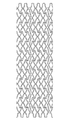
本発明のステントを図面に示した実施例を用いて説明する。
図1は、本発明のステントの一実施例の正面図である。図2は、図1に示したステントの部分拡大図である。図3は、図1に示したステントの拡張前の展開図である。
この実施例のステント1は、略管状体に形成され、生体内管腔への挿入のための直径を有し、管状体の内部より半径方向に広がる力が付加された時に拡張可能なステントである。ステント1は、多数の屈曲部5aを有する波状要素により環状に形成された第1の波状環状体12aと、第1の波状環状体12aの谷部に山部が近接するようにステント1の軸方向に配置されるとともに線状屈曲部5aを有する波状要素により環状に形成された第2の波状環状体12bと、第1の波状環状体12aの谷部と第2の波状環状体12bの山部とを接続する複数の接続部6とからなる環状ユニット4からなり、さらに、環状ユニット4は、ステント1の軸方向に複数配列されるとともに、隣り合う環状ユニットを接続部形成部位にて連結する連結部7を備える。さらに、連結部7は、隣り合う環状ユニット4間に複数かつ向かい合う位置もしくはステントの中心軸に対してほぼ等角度配置となるように設けられているものである。
The stent of the present invention will be described with reference to the embodiments shown in the drawings.
FIG. 1 is a front view of an embodiment of the stent of the present invention. FIG. 2 is a partially enlarged view of the stent shown in FIG. FIG. 3 is a development view of the stent shown in FIG. 1 before expansion.
The stent 1 of this embodiment is a stent that is formed into a substantially tubular body, has a diameter for insertion into a lumen in a living body, and is expandable when a force that extends radially from the inside of the tubular body is applied. is there. The stent 1 includes a first corrugated
このステント1は、いわゆるバルーンエキスパンダブルステントである。
ステント1は、図1ないし図3に示すように、複数の環状ユニット4が、ステント1の軸方向にほぼ直線状となるように配列されるとともに、隣り合う環状ユニットの波状要素(波状環状体12bと12a)を接続部6の形成部位において連結する連結部7を備えている。ステント1は、見方を変えれば、多数の環状ユニット4が、連結部7により連結したことにより構成された管状体である。
ステント1の環状ユニット12a、12bは、図1およびその展開図である図3に示すように、ほぼ同じピッチの6つの山と谷を有し、環状に連続した無端の波状体により構成されている。なお、環状ユニットの山(もしくは谷)の数は、4〜7が好適である。そして、第1の波状環状体12aの谷部に山部が近接するように軸方向に配置された第2の波状環状体12bは、第1の波状環状体の谷部と第2の波状環状体の山部とが複数の短い接続部6により接続され、一つの環状ユニット4を構成している。この実施例では、第1の波状環状体12aのすべての谷部と第2の波状環状体12bのすべて山部とが接続部6により接続されており、一つの環状ユニット4は、6つ(環状ユニットの山もしくは谷の数)の接続部6を備えている。
The stent 1 is a so-called balloon expandable stent.
As shown in FIGS. 1 to 3, the stent 1 has a plurality of
The
そして、上記のように構成された環状ユニット4は、ステント1の軸方向に複数(この実施例では、12個)配列されるとともに、隣り合う環状ユニットを連結する連結部7を備えており、これにより、筒状のステント1が形成されている。そして、連結部7は、隣り合う環状ユニット4を複数カ所連結するように設けられている。2つの隣り合う環状ユニット間に設けられる連結部の数は、2〜4個が好ましい。さらに、連結部7は、隣り合う連結部と連続しないように配置されている。ステント1では、連結部7は、隣り合う環状ユニット4間に、図1ないし図3に示すように、2つ設けられている。つまり、隣り合う環状ユニット4は、2カ所において連結されている。
そして、環状ユニット4の複数の接続部のうち少なくとも一つの接続部は、第1の波状環状体12aの谷部と第2の波状環状体12bの山部が一体化した一体化部4aとなっている。また、他の接続部6は細線状接続部となっている。そして、環状ユニット間に複数設けられた連結部の少なくとも一つの連結部7aは、隣り合う環状ユニット4の一体化部4a相互を連結している。さらに、他の連結部7bは、隣り合う環状ユニット4の細線状接続部6の形成部位相互を連結している。つまり、この実施例のステントでは、隣り合う環状ユニットは、各環状ユニットが備える第1の波状環状体12aの谷部と第2の波状環状体12bの山部が一体化した一体化部4aにより連結されているので、ユニット4相互は十分な連結強度を備える。さらに、隣り合う環状ユニットは、細線状接続部6の形成部位相互を連結する他の(第2の)連結部7bを備えている。このため、ステントの生体内留置後の伸張を抑制することができ、かつ、一体化部における連結でないため、湾曲障害とならない。
And the cyclic |
Then, at least one of the plurality of connecting portions of the
そして、環状ユニット4間を連結する複数の連結部7は、ステント1の中心軸に対して所定角度斜めとなっている。言い換えれば、ステントをステントの中心軸に平行に長手方向に切断し展開した状態において、連結部は、ステントの長手方向に対して、所定角度で傾斜している。さらに、図面に示す実施例のステント1では、2つの同じ隣り合う環状ユニットを連結する連結部は同じ方向にかつほぼ同じ角度で傾斜している。また、この実施例のステント1では、ステントの軸方向に隣り合う連結部は、傾斜方向が異なるものとなっている。さらに、連結部7は、隣り合う連結部と連続しないように配置されている。また、連結部7(7a、7b)とこの連結部7(7a、7b)とステント1の軸方向に隣り合う連結部7(7a、7b)は、ステント1の中心軸に対して所定角度ずつずれることにより、連結部7(7a、7b)が断続する螺旋状となるように配置されている。つまり、複数の連結部7a、7bとこの複数の連結部7a、7bとステントの軸方向に隣り合う複数の連結部7a、7bは、ステントの中心軸に対して所定角度(図3に示す実施例では、約60度)ずつずれるように配置されており、これにより、連結部7a、7bは、断続する複数(2本)の螺旋状となるように配置されたものとなっている。
The plurality of connecting
このように、ステント1において、連結部7a,7bは、図3に示すように、ステントの軸方向に対して連続せず、かつ、2本の螺旋状に配置された状態となり、さらに、軸方向に対して隣り合う位置の連結部は傾斜方向が異なったものとなっている。また、一体化部は、1本の螺旋状に配置された状態となっている。
これにより、ステントは、全体として湾曲方向性を持たない良好な変形が可能なものとなっている。湾曲方向性を持たないとは、易変形方向および難変形方向を持たないことを意味する。連結部をステントの軸方向に連続しないものとすることにより、一つの環状ユニット4が血管の変形に追従するように変化した時の負荷が、隣り合わない環状ユニット4にまで直接的(もしくは直線的)に伝達されることを抑制でき、環状ユニット個々の独立した拡張機能を発揮する。さらに、連結部の配置が、ステント1全体から見て螺旋的なものとなっていれば、隣り合わない環状ユニットによる影響をより受けにくくなる。
Thus, in the stent 1, as shown in FIG. 3, the connecting
As a result, the stent can be deformed satisfactorily without having a bending directionality as a whole. Not having a bending directionality means having no easy deformation direction and no difficult deformation direction. By making the connecting portion not continuous in the axial direction of the stent, the load when one
さらに、このステント1では、一つの環状ユニットの隣り合う屈曲部間に形成される空間には、隣り合う環状ユニットの波状環状体の屈曲部5aの頂点部分が侵入していることが好ましい。このようにすることにより、ステント1は、波状環状体がステント1の軸方向に見ると部分的に重なった状態となっている。このステント1を拡張させた時に、個々の構成要素がステント1の軸方向に短くなっても、ステント1の側面における隙間の増加が少なく、より確実に血管の狭窄部を拡張できかつ、病変部位を隙間なく押さえることができる。
Furthermore, in this stent 1, it is preferable that the apex part of the bending
ステント1は、非拡張時の直径は、0.8〜1.8mm程度が好適であり、特に、0.9〜1.4mmがより好ましい。また、ステント1の非拡張時の長さは、9〜40mm程度が好適である。また、一つの波状環状体12a,12bの長さは、0.7〜2.0mm程度が好適であり、一つの環状ユニットの長さは、1.5〜4.0mm程度が好適であり、特に、2.0〜3.0mmがより好ましい。また、一つの波状環状体12a,12bの山の数(言い換えれば、谷の数)は、4〜8が好ましく、特に、5〜7が好ましい。また、細線状接続部6の長さは、0.01〜0.5mm程度が好適である。また、細線状接続部の幅は、破断可能とする場合には、0.02〜0.04mm、より好ましくは0.025〜0.035mmである。また、細線状接続部の幅は、破断させない場合には、0.06〜0.15mm、より好ましくは0.08〜0.13mmである。そして、一体化部の幅は、0.06〜0.15mm、より好ましくは0.08〜0.13mmである。
The stent 1 preferably has a non-expanded diameter of about 0.8 to 1.8 mm, and more preferably 0.9 to 1.4 mm. The length of the stent 1 when not expanded is preferably about 9 to 40 mm. In addition, the length of one wavy
環状ユニットの数としては、3〜50が好適である。また、隣り合う環状ユニットの構成要素(環状ユニット)がステント1の軸方向に重なる長さは、0.5〜1mmが好適である。また、環状ユニット間の中心間距離は、1.3〜2.5mmが好適である。連結部7の長さは、1.4〜2.7mmが好適である。さらに、ステント1の中心軸に対する連結部の傾斜角(展開図で見た時の長手方向に対する傾斜角)は、0°〜45°程度が好ましく、特に、5°〜25°が好適である。また、ステント1は、成形時(圧縮前)の直径は、1.5〜3.5mm程度が好適であり、特に、2.0〜3.0mmがより好ましい。さらに、ステント1の肉厚としては、0.05〜0.15mm程度が好適であり、特に、0.08〜0.12mmが好適であり、波状要素の幅は、0.07〜0.15mm程度が好適であり、特に、0.08〜0.13mmが好適である。
The number of annular units is preferably 3-50. Moreover, 0.5-1 mm is suitable for the length with which the component (annular unit) of an adjacent annular unit overlaps with the axial direction of the stent 1. FIG. Moreover, 1.3-2.5 mm is suitable for the distance between centers between annular units. The length of the connecting
なお、上述した実施例のステント1は、隣り合う環状ユニット間が2つの連結部により連結されているタイプのものである。このため、連結部は、ステントの中心軸に対して向かい合う位置に配置されている。しかし、この実施例に限定されるものではなく、隣り合う環状ユニット間には、3〜4(上記の2を含めれば2〜4)の連結部を設けてもよい。この場合には、連結部はステントの中心軸に対してほぼ等角度配置となるように設けられる。つまり、隣り合う環状ユニット間に3つの連結部を設ける場合には、約120度毎の配置となり、4つの連結部を設ける場合には、約90度毎の配置となる。また、このように、隣り合う環状ユニット間に3以上の連結部を設ける場合においても、一つの環状ユニットは、一つの一体化部しか備えないものとすることが好ましい。つまり、一つの連結部のみが隣り合う環状ユニットの一体化部を連結するものとし、他の2以上の連結部は、細線状接続部形成部位を連結するものとすることが好ましい。 In addition, the stent 1 of the Example mentioned above is a type with which the adjacent annular units are connected by two connection parts. For this reason, the connection part is arrange | positioned in the position facing the center axis | shaft of a stent. However, it is not limited to this Example, You may provide 3-4 (2-4 if said 2 is included) between adjacent annular units. In this case, the connecting portions are provided so as to be arranged at substantially equal angles with respect to the central axis of the stent. That is, when three connecting portions are provided between adjacent annular units, the arrangement is about 120 degrees, and when four connecting portions are provided, the arrangement is about 90 degrees. In addition, even when three or more connecting portions are provided between adjacent annular units as described above, it is preferable that one annular unit includes only one integrated portion. That is, it is preferable that only one connecting portion connects the adjacent integrated portions of the annular units, and the other two or more connecting portions connect the thin line connecting portion forming portions.
ステント1の形成材料としては、ある程度の生体適合性を有するものが好ましく、例えば、ステンレス鋼、タンタルもしくはタンタル合金、プラチナもしくはプラチナ合金、金もしくは金合金、コバルトベース合金等が考えられる。またステント形状を作製した後に貴金属メッキ(金、プラチナ)をしてもよい。ステンレス鋼としては、最も耐腐食性のあるSUS316Lが好適である。 The material for forming the stent 1 is preferably a material having a certain degree of biocompatibility. For example, stainless steel, tantalum or a tantalum alloy, platinum or a platinum alloy, gold or a gold alloy, a cobalt base alloy, or the like can be considered. Moreover, after producing the stent shape, precious metal plating (gold, platinum) may be performed. As stainless steel, SUS316L having the most corrosion resistance is suitable.
また、ステント1は面取りされていることが好ましい。ステント1の面取り方法としては、ステントを最終形状に形成した後、化学研磨、電解研磨もしくは機械研磨することにより行うことができる。化学研磨としては、ステンレス化学研磨液に浸漬することにより行うことが好ましい。ステンレス化学研磨液としては、ステンレスを溶解できるものであればよく、例えば、塩酸と硝酸からなる混合液を基本成分とし、これに、溶解速度調整、平滑化および光沢性付与のための有機硫黄化合物および界面活性剤を添加したものが好ましい。 The stent 1 is preferably chamfered. The chamfering method of the stent 1 can be performed by forming the stent into a final shape and then performing chemical polishing, electrolytic polishing or mechanical polishing. The chemical polishing is preferably performed by dipping in a stainless chemical polishing solution. The stainless steel chemical polishing liquid is not particularly limited as long as it can dissolve stainless steel. For example, a mixed liquid composed of hydrochloric acid and nitric acid is used as a basic component, and an organic sulfur compound for adjusting the dissolution rate, smoothing, and imparting gloss. And those to which a surfactant is added are preferred.
さらに、ステント1の最終形状を作製した後、焼きなましすることが好ましい。焼きなましを行うことにより、ステント全体の柔軟性および可塑性が向上し、屈曲した血管内での留置性が良好となる。焼きなましを行わない場合に比べて、ステント1を拡張した後の拡張前形状に復元しようとする力、特に、屈曲した血管部位で拡張した時に発現する直線状に復帰しようとする力が減少し、屈曲した血管内壁に与える物理的な刺激が減少し、再狭窄の要因を減少させることができる。焼きなましは、ステント表面に酸化被膜が形成されないように、不活性ガス雰囲気下(例えば、窒素と水素の混合ガス)にて、900〜1200℃に加熱した後、ゆっくりと冷却することにより行うことが好ましい。 Furthermore, it is preferable to anneal after producing the final shape of the stent 1. By performing the annealing, the flexibility and plasticity of the entire stent are improved, and the indwellability in the bent blood vessel is improved. Compared to the case where annealing is not performed, the force to restore the shape before expansion after the stent 1 is expanded, in particular, the force to return to the linear shape that is manifested when expanding at a bent blood vessel site, The physical stimulation applied to the bent inner wall of the blood vessel is reduced, and the factor of restenosis can be reduced. Annealing is performed by heating to 900 to 1200 ° C. in an inert gas atmosphere (for example, a mixed gas of nitrogen and hydrogen) and then slowly cooling so that an oxide film is not formed on the stent surface. preferable.
次に、本発明の他の実施例のステントについて、図面を参照して説明する。
図4は、本発明の他の実施例のステントの一実施例の正面図である。図5は、図4に示したステントの部分拡大図である。図6は、図4に示したステントの展開図である。
この実施例のステント10は、略管状体に形成され、生体内管腔への挿入のための直径を有し、管状体の内部より半径方向に広がる力が付加された時に拡張可能なステントである。ステント10は、半径方向に広がる力が付加された時に伸張する多数の線状屈曲部と開口を有する複数の略多角形状線状体13を環状となるように複数の接続部16により接続した環状ユニット14がステントの軸方向に複数配列され、かつ、隣り合う環状ユニット14を接続部にて連結するとともにステントの軸方向に連続しない連結部15を備え、さらに、連結部は、隣り合う環状ユニット間に複数かつ向かい合う位置もしくはステントの中心軸に対してほぼ等角度配置となるように設けられている。
Next, a stent according to another embodiment of the present invention will be described with reference to the drawings.
FIG. 4 is a front view of an embodiment of a stent according to another embodiment of the present invention. FIG. 5 is a partially enlarged view of the stent shown in FIG. FIG. 6 is a development view of the stent shown in FIG. 4.
The
このステントは、いわゆるバルーンエキスパンダブルステントである。
この実施例のステントのように、略多角形状線状体13は、ステントの軸方向に長いつぶれた形状となっていることが好ましい。さらに、この実施例のステントのように、ステントの両端に位置する略多角形状線状体13は、外側に位置する部分が略半楕円状となっていることが好ましい。さらに、この実施例のステントのように、環状ユニットの隣り合う略多角形状線状体13の屈曲部11a間により形成される空間には、隣接する他の環状ユニット14の略多角形状線状体13の屈曲部11aの頂点部分が侵入していることが好ましい。
This stent is a so-called balloon expandable stent.
Like the stent of this embodiment, it is preferable that the substantially polygonal
ステント10は、図4、図5および図4の展開図である図6に示すように、ステント10の軸方向に長くかつ線状屈曲部11aと中央部開口を有する略多角形状線状体13が、ステントの中心軸に対してほぼ等角度配置にて略円周上に配列され、かつ、略多角形状線状体13の円周方向の隣接部(側部)間が接続部16にて接続された環状ユニット14からなり、かつ、複数の環状ユニット14がステント10の軸方向に並んでいる。さらに、一つの環状ユニット14の接続部16と隣り合う環状ユニット14の接続部16とが連結部15により少なくとも2カ所連結されている。ステント10は、見方を変えれば、多数の環状ユニット14が、連結部15により連結したことにより構成された管状体である。
As shown in FIG. 6, which is a development view of FIGS. 4, 5 and 4, the
環状ユニット14は、この実施例では、ほぼ等角度間隔に配置された6つの略多角形状線状体13を有する。一つの略多角形状線状体13は、ステント10の軸方向に長い略菱形状に形成され、かつ、中央が略多角形状線状体13の形状に対応して、略菱形に開口し、ステントの軸方向の両端部が線状屈曲部11aとなっている。このように、各略多角形状線状体13は、個々独立した閉鎖系をなす形状、言い換えれば、略多角形状線状体13は、ステント10の側面にて開口するリング状要素である。略多角形状線状体13がこのような形状を有するため、強い拡張保持力を発揮する。また、各略多角形状線状体13は、ステント10の中心軸より全体がほぼ等距離となるように、円周方向に湾曲している。
In this embodiment, the
略多角形状線状体13は、ステント10の軸方向の側部の中心と半径方向に隣り合う他の略多角形状線状体13の軸方向の側部の中心とが短い接続部16により接続されている。つまり、接続部16は、各略多角形状線状体13を円周方向にて接続している。接続部16は、ステント10が拡張されても実質的に変化しないので、拡張する時の力が各略多角形状線状体13の中心にかかりやすく、各略多角形状線状体13は均一に拡張(変形)可能である。
略多角形状線状体13の数は、6つに限られるものではなく、4〜8が好適である。また、略多角形状線状体13の形状は、ステントの軸方向に向かい合う頂点を有する多角形状であることが好ましく、特に、略菱形、六角形、八角形などであってよい。好ましくは、ステント拡張時の変形の安定性より、略菱形状である。
The substantially polygonal
The number of the substantially polygonal
環状ユニット14の接続部16と隣り合う環状ユニット14の接続部16とは、比較的長く(接続部に比べて長く)、ステント10の軸方向に平行に形成された連結部15により連結されている。具体的には、環状ユニット14と隣り合う環状ユニット14とは、接続部16間を連結する連結部15により連結されている。
これら連結部15は、ステント10が拡張されても実質的に変化しない。連結部15および接続部16が、ステント10の拡張によって、実質的に変化しないので、ステント10全体の全長は、拡張前と拡張後においてほとんど変化せず、拡張後にステントが極端に短くなることがない。言い換えれば、拡張要素を接続する接続部16は、ステントが拡張しても軸方向での移動がなく、この接続部同士を軸に平行な連結部15で連結してあるのでステントの全長がほとんど短縮しないのである。
連結部15は、隣り合う環状ユニット14を複数カ所連結するように設けられている。2つの隣り合う環状ユニット間に設けられる連結部の数は、2〜3個が好ましく、特に2個が好適である。さらに、連結部15は、軸方向に隣り合う連結部と連続しないように配置され、また、向き(角度)がずれて配置されている。
The connecting
These connecting
The connecting
そして、環状ユニット間を連結する複数の連結部は、ステント10の中心軸に対して所定角度斜めとなっている。言い換えれば、ステントをステントの中心軸に平行に長手方向に切断し展開した状態において、連結部は、ステントの長手方向に対して、所定角度で傾斜している。そして、この実施例のステント10では、同じ隣り合う環状ユニットを連結する連結部は同じ方向に傾斜している。さらに、図面に示す実施例のステント10では、同じ隣り合う環状ユニットを連結する連結部は同じ方向にかつほぼ同じ角度で傾斜している。また、ステントの軸方向に隣り合う連結部は、傾斜方向が異なるものとなっている。さらに、連結部15は、隣り合う連結部と連続しないように配置されている。また、連結部15とこの連結部15とステント1の軸方向に隣り合う連結部15は、ステント10の中心軸に対して所定角度ずつずれることにより、連結部15が断続する螺旋状となるように配置されている。つまり、複数の連結部15とこの複数の連結部15とステントの軸方向に隣り合う複数の連結部15は、ステントの中心軸に対して所定角度(図6に示す実施例では、約60度)ずつずれるように配置されており、これにより、連結部15は、断続する複数(2本)の螺旋状となるように配置されたものとなっている。
The plurality of connecting portions that connect the annular units are inclined at a predetermined angle with respect to the central axis of the
このように、ステント10において、連結部15は、図6に示すように、ステントの軸方向に対して連続せず、かつ、2本の螺旋状に配置された状態となり、さらに、軸方向に対して隣り合う位置の連結部は傾斜方向が異なったものとなっている。これにより、ステントは、全体として湾曲方向性を持たない良好な変形が可能なものとなっている。湾曲方向性を持たないとは、易変形方向および難変形方向を持たないことを意味する。連結部をステントの軸方向に連続しないものとすることにより、一つの環状ユニット14が血管の変形に追従するように変化した時の負荷が、隣り合わない環状ユニット14にまで直接的(もしくは直線的)に伝達されることを抑制でき、環状ユニット個々の独立した拡張機能を発揮する。さらに、連結部の配置が、ステント10全体から見て螺旋的なものとなっていれば、隣り合わない環状ユニットによる影響をより受けにくくなる。
Thus, in the
また、ステント10の両端に位置する略多角形状線状体13の外側部分13bは、略半楕円状となっている。このようにすることにより、端部での拡張力を十分なものとすることができ、かつ、留置される血管内壁およびバルーンに損傷を与えることを少なくすることができる。また、すべての略多角形状線状体13は、ステントの中心軸より全体がほぼ等距離となるように、円周方向に湾曲している。
さらに、このステント10では、環状ユニット14の隣り合う2つの略多角形状線状体13の屈曲部間に形成された空間には、隣接する環状ユニット14の略多角形状線状体13の屈曲部11aの頂点部分が侵入していることが好ましい。このようにすることにより、ステント10では、環状ユニットがステントの軸方向に見ると部分的に重なった状態となっている。ステント10を拡張させた時に、個々の略多角形状線状体13がステント10の軸方向に短くなっても、ステント10の側面における隙間の増加が少なく、より確実に血管の狭窄部を拡張できかつ、その維持もより高いものとなる。
Further, the
Further, in this
ステント10としては、非拡張時の直径が0.6〜1.8mm程度が好適であり、特に、0.8〜1.6mmがより好ましい。また、一つの環状ユニットの長さ、言い換えれば、一つの略多角形状線状体の軸方向の長さは、1.5〜4.0mm程度が好適であり、特に、2.0〜3.0mmがより好ましい。また、環状ユニットの数としては、3〜10、好ましくは3〜8が好適である。ステント10の中央部の環状ユニットの肉厚としては、0.05〜0.12mm程度が好適であり、特に、0.06〜0.10mmが好適である。ステントの肉厚としては、0.05〜0.09mm程度が好適である。また、ステント10は、成形時(圧縮前)の直径は、1.5〜3.5mm程度が好適であり、特に、2.0〜3.0mmがより好ましい。
The
なお、上述した実施例のステント10では、隣り合う環状ユニット間が2つの連結部により連結されているタイプのものであり、このため、連結部は、ステントの中心軸に対して向かい合う位置に配置されている。しかし、この実施例に限定されるものではなく、隣り合う環状ユニット間には、3〜4(上記の2を含めれば2〜4)の連結部を設けてもよい。この場合には、連結部はステントの中心軸に対してほぼ等角度配置となるように設けられる。つまり、隣り合う環状ユニット間に3つの連結部を設ける場合には、約120度毎の配置となる。
ステント10の形成材料としては、ある程度の生体適合性を有するものが好ましく、例えば、ステンレス鋼、タンタルもしくはタンタル合金、プラチナもしくはプラチナ合金、金もしくは金合金、コバルトベース合金等が考えられる。またステント形状を作製した後に貴金属メッキ(金、プラチナ)をしてもよい。ステンレス鋼としては、最も耐腐食性のあるSUS316Lが好適である。
In addition, in the
The material for forming the
さらに、ステント10の最終形状を作製した後、焼きなましすることが好ましい。焼きなましを行うことにより、ステント全体の柔軟性および可塑性が向上し、屈曲した血管内での留置性が良好となる。焼きなましを行わない場合に比べて、ステントを拡張した後の拡張前形状に復元しようとする力、特に、屈曲した血管部位で拡張した時に発現する直線状に復帰しようとする力が減少し、屈曲した血管内壁に与える物理的な刺激が減少し、再狭窄の要因を減少させることができる。焼きなましは、ステント表面に酸化被膜が形成されないように、不活性ガス雰囲気下(例えば、アルゴンガス)にて、900〜1200℃に加熱した後、ゆっくりと冷却することにより行うことが好ましい。
Furthermore, it is preferable to anneal after producing the final shape of the
また、ステント10は面取りされていることが好ましい。ステント10の面取り方法としては、ステントを最終形状に形成した後、化学研磨、電解研磨もしくは機械研磨することにより行うことができる。化学研磨としては、ステンレス化学研磨液に浸漬することにより行うことが好ましい。ステンレス化学研磨液としては、ステンレスを溶解できるものであればよく、例えば、塩酸と硝酸からなる混合液を基本成分とし、これに、溶解速度調整、平滑化および光沢性付与のための有機硫黄化合物および界面活性剤を添加したものが好ましい。
The
次に、本発明の血管拡張器具を図面に示す実施例を用いて説明する。
図7は、本発明の実施例の生体器官拡張器具の正面図である。図8は、図7に示した生体器官拡張器具の先端部の拡大部分断面図である。図9は、図7に示した生体器官拡張器具の後端部の拡大断面図である。
本発明の血管拡張器具100においては、チューブ状のシャフト本体部102と、シャフト本体部102の先端部に設けられた折り畳みおよび拡張可能なバルーン103と、折り畳まれた状態のバルーン103を被包するように装着され、かつバルーン103の拡張により拡張されるステント101とを備えるものである。
Next, the vasodilator of the present invention will be described with reference to the embodiments shown in the drawings.
FIG. 7 is a front view of the living organ dilator according to the embodiment of the present invention. 8 is an enlarged partial cross-sectional view of the distal end portion of the living organ dilator shown in FIG. FIG. 9 is an enlarged cross-sectional view of the rear end portion of the living organ dilator shown in FIG.
In the
ステント101としては、略管状体に形成され、生体内管腔への挿入のための直径を有し、該管状体の内部より半径方向に広がる力が付加された時に拡張可能なステントであって、半径方向に広がる力が付加された時に伸張する多数の線状屈曲部を備え、かつ屈曲部の頂点を含む部分がステントの内側に湾曲しているものが用いられている。
このようなステント101としては、例えば、上述したステント1もしくはステント10を用いることができる。
さらに、本発明の血管拡張器具100は、シャフト本体部102は、一端がバルーン103内と連通するバルーン拡張用ルーメンを備える。生体器官拡張器具100は、ステントの中央部となる位置のシャフト本体部の外面に固定されたX線造影性部材もしくはステントの中央部分の所定長の両端となる位置のシャフト本体部の外面に固定された2つのX線造影性部材を備えている。
この実施例の生体器官拡張器具100では、図7に示すように、シャフト本体部102は、シャフト本体部102の先端にて一端が開口し、シャフト本体部102の後端部にて他端が開口するガイドワイヤールーメン115を備えている。
The
As such a
Further, in the
In the living
この生体器官拡張器具100は、シャフト本体部102と、シャフト本体部102の先端部に固定されたステント拡張用バルーン103と、このバルーン103を上に装着されたステント101とを備える。シャフト本体部102は、内管112と外管113と分岐ハブ110とを備えている。
内管112は、図8および図9に示すように、内部にガイドワイヤーを挿通するためのガイドワイヤールーメン115を備えるチューブ体である。内管112としては、長さは、100〜2000mm、より好ましくは、150〜1500mm、外径が、0.1〜1.0mm、より好ましくは、0.3〜0.7mm、肉厚10〜150μm、より好ましくは、20〜100μmのものである。そして、内管112は、外管113の内部に挿通され、その先端部が外管113より突出している。この内管112の外面と外管113の内面によりバルーン拡張用ルーメン116が形成されており、十分な容積を有している。外管113は、内部に内管112を挿通し、先端が内管112の先端よりやや後退した部分に位置するチューブ体である。
外管113としては、長さは、100〜2000mm、より好ましくは、150〜1500mm、外径が、0.5〜1.5mm、より好ましくは、0.7〜1.1mm、肉厚25〜200μm、より好ましくは、50〜100μmのものである。
This biological
As shown in FIGS. 8 and 9, the
The
この実施例の生体器官拡張器具100では、外管113は、先端側外管113aと本体側外管113bにより形成され、両者が接合されている。そして、先端側外管113aは、本体側外管113bとの接合部より先端側の部分において、テーパー状に縮径し、このテーパー部より先端側が細径となっている。
先端側外管113aの細径部での外径は、0.50〜1.5mm、好ましくは0.60〜1.1mmである。また、先端側外管113aの基端部および本体側外管113bの外径は、0.75〜1.5mm、好ましくは0.9〜1.1mmである。
In the living
The outer diameter at the small diameter portion of the distal end side
そして、バルーン103は、先端側接合部103aおよび後端側接合部103bを有し、先端側接合部103aが内管112の先端より若干後端側の位置に固定され、後端側接合部103bが外管の先端に固定されている。また、バルーン103は、基端部付近にてバルーン拡張用ルーメン116と連通している。
内管112および外管113の形成材料としては、ある程度の可撓性を有するものが好ましく、例えば、ポリオレフィン(例えば、ポリエチレン、ポリプロピレン、エチレン−プロピレン共重合体、エチレン−酢酸ビニル共重合体など)、ポリ塩化ビニル、ポリアミドエラストマー、ポリウレタン等の熱可塑性樹脂、シリコーンゴム、ラテックスゴム等が使用でき、好ましくは上記の熱可塑性樹脂であり、より好ましくは、ポリオレフィンである。
The
As a material for forming the
バルーン103は、図8に示すように、折り畳み可能なものであり、拡張させない状態では、内管112の外周に折り畳まれた状態となることができるものである。バルーン103は、装着されるステント101を拡張できるようにほぼ同一径の筒状部分(好ましくは、円筒部分)となった拡張可能部を有している。略円筒部分は、完全な円筒でなくてもよく、多角柱状のものであってもよい。そして、バルーン103は、上述のように、先端側接合部103aが内管112にまた後端側接合部103bが外管113の先端に接着剤または熱融着などにより液密に固着されている。また、このバルーン103では、拡張可能部と接合部との間がテーパー状に形成されている。
As shown in FIG. 8, the
バルーン103は、バルーン103の内面と内管112の外面との間に拡張空間103cを形成する。この拡張空間103cは、後端部ではその全周において拡張用ルーメン116と連通している。このように、バルーン103の後端は、比較的大きい容積を有する拡張用ルーメンと連通しているので、拡張用ルーメン116よりバルーン内への拡張用流体の注入が確実である。
バルーン103の形成材料としては、ある程度の可撓性を有するものが好ましく、例えば、ポリオレフィン(例えば、ポリエチレン、ポリプロピレン、エチレン−プロピレン共重合体、エチレン−酢酸ビニル共重合体、架橋型エチレン−酢酸ビニル共重合体など)、ポリ塩化ビニル、ポリアミドエラストマー、ポリウレタン、ポリエステル(例えば、ポリエチレンテレフタレート)、ポリアリレーンサルファイド(例えば、ポリフェニレンサルファイド)等の熱可塑性樹脂、シリコーンゴム、ラテックスゴム等が使用できる。特に、延伸可能な材料であることが好ましく、バルーン103は、高い強度および拡張力を有する二軸延伸されたものが好ましい。
The
As a material for forming the
バルーン103の大きさとしては、拡張された時の円筒部分(拡張可能部)の外径が、2〜4mm、好ましくは2.5〜3.5mmであり、長さが10〜50mm、好ましくは20〜40mmである。また、先端側接合部103aの外径が、0.9〜1.5mm、好ましくは1〜1.3mmであり、長さが1〜5mm、好ましくは1〜1.3mmである。また、後端側接合部103bの外径が、1〜1.6mm、好ましくは1.1〜1.5mmであり、長さが1〜5mm、好ましくは、2〜4mmである。
As the size of the
そして、この血管拡張器具100は、図8に示すように、拡張された時の円筒部分(拡張可能部)の両端となる位置のシャフト本体部の外面に固定された2つのX線造影性部材117、118を備えている。なお、ステント101の中央部分の所定長の両端となる位置のシャフト本体部102(この実施例では、内管112)の外面に固定された2つのX線造影性部材を備えるものとしてもよい。さらに、ステントの中央部となる位置のシャフト本体部の外面に固定された単独のX線造影性部材を設けるものとしてもよい。
X線造影性部材117、118は、所定の長さを有するリング状のもの、もしくは線状体をコイル状に巻き付けたものなどが好適であり、形成材料は、例えば、金、白金、タングステンあるいはそれらの合金、あるいは銀−パラジウム合金等が好適である。
As shown in FIG. 8, the
The
また、図9に示すように、内管112と外管113との間(バルーン拡張用ルーメン116内)には、線状の剛性付与体133が挿入されている。剛性付与体133は、生体器官拡張器具100の可撓性をあまり低下させることなく、屈曲部位での生体器官拡張器具100の本体部102の極度の折れ曲がりを防止するとともに、生体器官拡張器具100の先端部の押し込みを容易にする。剛性付与体133の先端部は、他の部分より研磨などの方法により細径となっている。また、剛性付与体133は、細径部分の先端が、本体部外管113の先端部付近まで延びていることが好ましい。剛性付与体としては、金属線であることが好ましく、線径0.05〜1.50mm、好ましくは0.10〜1.00mmのステンレス鋼等の弾性金属、超弾性合金などであり、特に好ましくは、ばね用高張力ステンレス鋼、超弾性合金線である。
As shown in FIG. 9, a linear
この実施例の生体器官拡張器具100では、図9に示すように、基端に分岐ハブ110が固定されている。
分岐ハブ110は、ガイドワイヤールーメン115と連通しガイドワイヤーポートを形成するガイドワイヤー導入口109を有し、内管112に固着された内管ハブ122と、バルーン拡張用ルーメン116と連通しインジェクションポート111を有し、外管113に固着された外管ハブ123とからなっている。そして、外管ハブ123と内管ハブ122とは、固着されている。この分岐ハブ110の形成材料としては、ポリカーボネート、ポリアミド、ポリサルホン、ポリアリレート、メタクリレート−ブチレン−スチレン共重合体等の熱可塑性樹脂が好適に使用できる。
In the living
The
この実施例では、外管113の末端部には、折曲がり防止用チューブ150を有している。折曲がり防止用チューブ150は、熱収縮性を有するものにて、熱収縮後の内径が外管113の外径より若干小さくなるように形成し、このように形成されたチューブ150を外管113の末端部に被嵌し、加熱(例えば、熱風をあてる)させて収縮させることにより取り付けられている。そして、折曲がり防止用チューブ150は、外管ハブ123に止めピン152により固定されている。この固定方法は、外管113の後端に後端部分以外の部分の外径が外管113の内径とほぼ等しく、拡径した後端部分を有する止めピン152を差し込み、外管113をその先端から外管ハブ123に挿入し、外管ハブ123の内面に設けられた突起154を止めピン152の後端部分が越えるまで押し込むことにより行われている。さらに、外管ハブ123と折曲がり防止用チューブ150との接触面に接着剤を塗布して固着してもよい。
In this embodiment, a
また、内管112の末端部には、折曲がり防止用チューブ160を有している。このチューブ160は、熱収縮性を有するものにて、熱収縮後の内径が内管112の外径より若干小さくなるように形成され、この熱収縮性を有するチューブ160を内管112の末端部に被嵌し、加熱(例えば、熱風をあてる)させて収縮させることにより容易に取り付けることができる。そして、剛性付与体133の基端部は、この収縮チューブ160により内管112の外面に固定されている。そして、折曲がり防止用チューブ160を取り付けた内管112は、内管ハブ122に固定されている。この固定方法は、内管112の後端に後端部分以外の部分の外径が内管112の内径とほぼ等しく、拡径した後端部分を有する止めピン162を差し込み、内管112をその先端から内管ハブ122に挿入し、内管ハブ122の内面に設けられた突起164を止めピン162の後端部分が越えるまで押し込むことにより行われている。さらに、内管ハブ122と折曲がり防止用チューブ160との接触面に接着剤を塗布して固着してもよい。
外管ハブ、内管ハブおよびその形成材料としては、ポリカーボネート、ポリアミド、ポリサルホン、ポリアリレート、メタクリレート−ブチレン−スチレン共重合体等の熱可塑性樹脂が好適に使用できる。
In addition, a bending
A thermoplastic resin such as polycarbonate, polyamide, polysulfone, polyarylate, methacrylate-butylene-styrene copolymer can be suitably used as the outer tube hub, the inner tube hub, and the material for forming the hub.
そして、内管ハブ122と外管ハブ123とは固定されている。この固定は、外管113の基端部に取り付けられた外管ハブ123の後端から内管112をその先端から挿入し接合することにより行われている。またこの時、内管ハブ122と外管ハブ123との接合部に接着剤を塗布して行うことにより確実に両者を固着することができる。
なお、生体器官拡張器具100の基端の構造は、上記のようなものに限定されるものではなく、分岐ハブ110を設けず、ガイドワイヤールーメン115、バルーン拡張用ルーメン116それぞれに、例えば後端に開口部を形成するポート部材を有するチューブを液密に取り付けるようにしてもよい。
The
Note that the structure of the proximal end of the living
本発明のステントの具体的実施例について説明する。
(実施例1)
ステンレス鋼(SUS316L)の直径2.0mm、肉厚0.095mmのものを、長さ20mmに切断した金属パイプを用いた。
レーザー加工機として、NEC社製のYAGレーザー(商品名SL116E)を用いた。金属パイプを軸がぶれないようにチャック機構の付いた回転モーター付治具にセットし、さらにこれを数値制御可能なXYテーブル上にセットした。そして、XYテーブルおよび回転モーターをパーソナルコンピュータに接続し、パーソナルコンピュータの出力が、XYテーブルの数値制御コントローラーおよび回転モーターに入力されるものとした。パーソナルコンピュータ内には図面ソフトが記憶されており、ここに、図3に示すような成型時の構図のステントの展開図面を入力した。
このような構成により、パーソナルコンピュータより出力される図面データに基づいて、XYテーブルおよび回転モーターが駆動し、そこにレーザーを照射することにより、ステント構造物を作製した。上記金属パイプのレーザー加工条件としては、電流値25A,出力1.5W駆動スピード10mm/分にて行った。
そして、作製したステント構造物をステンレス用化学研磨液(三新化学工業株式会社製、商品名サンビット505,塩酸と硝酸からなる混合液を基本成分とし有機硫黄化合物および界面活性剤が添加されたもの)を約98℃加温したものに、約10分間浸漬し、面取り(バリ取り、化学研磨)を行い、本発明のステントを作製した。
Specific examples of the stent of the present invention will be described.
Example 1
A metal pipe obtained by cutting a stainless steel (SUS316L) having a diameter of 2.0 mm and a wall thickness of 0.095 mm into a length of 20 mm was used.
A YAG laser (trade name SL116E) manufactured by NEC was used as the laser processing machine. The metal pipe was set on a jig with a rotary motor with a chuck mechanism so that the shaft would not shake, and this was set on an XY table that could be numerically controlled. The XY table and the rotary motor were connected to a personal computer, and the output of the personal computer was input to the numerical control controller and the rotary motor of the XY table. Drawing software is stored in the personal computer, and a developed drawing of a stent having a composition at the time of molding as shown in FIG. 3 was input thereto.
With such a configuration, based on the drawing data output from the personal computer, the XY table and the rotary motor are driven, and a laser is irradiated to the XY table to produce a stent structure. The laser processing conditions for the metal pipe were as follows: current value 25 A, output 1.5 W, driving
And the produced stent structure was a chemical polishing liquid for stainless steel (manufactured by Sanshin Chemical Industry Co., Ltd., trade name Sunbit 505, mixed liquid consisting of hydrochloric acid and nitric acid as a basic component, and an organic sulfur compound and a surfactant were added. The product was dipped in a product heated at about 98 ° C. for about 10 minutes and chamfered (deburred and chemically polished) to produce the stent of the present invention.
このようにして作製されたステント形成体は、環状ユニット数12、隣り合う環状ユニット間に向かい合う位置に2つの連結部を有し、連結部のステントの軸方向のずれが約60度であり、全長が、20mm、外径2.0mm、波状要素(波状環状体)および連結部を構成する部分の幅は、0.12mm、接続部の幅は、0.12mm、一体化部の幅は、0.12mm、長さは、0.1mm、ステント全体の肉厚は、約0.08mmであった。 The stent formed body thus produced has 12 annular units, two connecting portions facing each other between adjacent annular units, and the axial displacement of the connecting portion of the stent is about 60 degrees. The overall length is 20 mm, the outer diameter is 2.0 mm, the width of the portion constituting the wavy element (the wavy annular body) and the connecting portion is 0.12 mm, the width of the connecting portion is 0.12 mm, and the width of the integrated portion is The thickness was 0.12 mm, the length was 0.1 mm, and the thickness of the entire stent was about 0.08 mm.
そして、このステント形成体をPTCA用拡張カテーテル(バルーンカテーテル)のバルーン部に被嵌し、マウント装置に挿入し、ステントをステントの外面から中心に向かって均一に圧縮して、外径1.0mmに縮径させて、バルーン状に装着させて、図7ないし図9に示すような構造を備える本発明の生体器官拡張器具を作製した。 Then, this stent-formed body is fitted on the balloon portion of the PTCA dilatation catheter (balloon catheter), inserted into the mounting device, and the stent is uniformly compressed from the outer surface of the stent toward the center to obtain an outer diameter of 1.0 mm. The biological organ dilating instrument of the present invention having a structure as shown in FIGS. 7 to 9 was produced by reducing the diameter to a balloon shape.
(比較例1)
パーソナルコンピュータ内に入力するステント成型時の構図を図10のものとした以外は、実施例1と同様に行い比較例のステントを作製した。
このようにして作製されたステント形成体は、環状ユニット数12、隣り合う環状ユニット間に向かい合う位置に一つのみの連結部を有し、連結部のステントの軸方向のずれが約180度であり、全長が、20mm、外径2.0mm、波状要素(波状環状体)および連結部を構成する部分の幅は、0.12mm、接続部の幅は、0.12mm、一体化部の幅は、0.12mm、長さは、0.1mm、ステント全体の肉厚は、約0.08mmであった。
そして、このステント形成体をPTCA用拡張カテーテル(バルーンカテーテル)のバルーン部に被嵌し、マウント装置に挿入し、ステントをステントの外面から中心に向かって均一に圧縮して、外径1.0mmに縮径させて、バルーン状に装着させて、生体器官拡張器具を作製した。
(Comparative Example 1)
A stent of a comparative example was manufactured in the same manner as in Example 1 except that the composition at the time of stent molding input into the personal computer was changed to that shown in FIG.
The stent formed body thus produced has 12 annular units, and has only one connecting portion at a position facing between adjacent annular units, and the axial displacement of the connecting portion of the stent is about 180 degrees. Yes, the overall length is 20 mm, the outer diameter is 2.0 mm, the width of the wavy element (the wavy annular body) and the connecting portion is 0.12 mm, the width of the connecting portion is 0.12 mm, and the width of the integrated portion Was 0.12 mm, the length was 0.1 mm, and the thickness of the entire stent was about 0.08 mm.
Then, this stent-formed body is fitted on the balloon portion of the PTCA dilatation catheter (balloon catheter), inserted into the mounting device, and the stent is uniformly compressed from the outer surface of the stent toward the center to obtain an outer diameter of 1.0 mm. The living body organ dilator was produced by reducing the diameter of the organ to a balloon shape.
(比較例2)
パーソナルコンピュータ内に入力するステント成型時の構図を図11のものとした以外は、実施例1と同様に行い比較例のステントを作製した。
このようにして作製されたステント形成体は、環状ユニット数12、隣り合う環状ユニット間に向かい合う位置に2つの連結部を有し、かつ、連結部が連続すし、全長が、20mm、外径2.0mm、波状要素(波状環状体)および連結部を構成する部分の幅は、0.12mm、接続部の幅は、0.12mm、一体化部の幅は、0.12mm、長さは、0.1mm、ステント全体の肉厚は、約0.08mmであった。
そして、このステント形成体をPTCA用拡張カテーテル(バルーンカテーテル)のバルーン部に被嵌し、マウント装置に挿入し、ステントをステントの外面から中心に向かって均一に圧縮して、外径1.0mmに縮径させて、バルーン状に装着させて、生体器官拡張器具を作製した。
(Comparative Example 2)
A stent of a comparative example was manufactured in the same manner as in Example 1 except that the composition at the time of stent molding input into the personal computer was changed to that shown in FIG.
The stent-formed body thus produced has 12 annular units, two connecting portions facing each other between adjacent annular units, the connecting portions are continuous, the total length is 20 mm, and the outer diameter is 2 0.02 mm, the width of the portion constituting the wave element (the wave ring) and the connecting portion is 0.12 mm, the width of the connecting portion is 0.12 mm, the width of the integrated portion is 0.12 mm, and the length is The wall thickness of the entire stent was about 0.08 mm.
Then, this stent-formed body is fitted on the balloon portion of the PTCA dilatation catheter (balloon catheter), inserted into the mounting device, and the stent is uniformly compressed from the outer surface of the stent toward the center to obtain an outer diameter of 1.0 mm. The living body organ dilator was produced by reducing the diameter of the organ to a balloon shape.
(実施例2)
ステンレス鋼(SUS316L)の直径2.0mm、肉厚0.095mmのものを、長さ50mmに切断した金属パイプを用いた。
レーザー加工機として、NEC社製のYAGレーザー(商品名SL116E)を用いた。金属パイプを軸がぶれないようにチャック機構の付いた回転モーター付治具にセットし、さらにこれを数値制御可能なXYテーブル上にセットした。そして、XYテーブルおよび回転モーターをパーソナルコンピュータに接続し、パーソナルコンピュータの出力が、XYテーブルの数値制御コントローラーおよび回転モーターに入力されるものとした。パーソナルコンピュータ内には図面ソフトが記憶されており、ここに、図6に示す成型時の構図のステントの展開図面を入力した。
このような構成により、パーソナルコンピュータより出力される図面データに基づいて、XYテーブルおよび回転モーターが駆動し、そこにレーザーを照射することにより、ステント構造物を作製した。上記金属パイプのレーザー加工条件としては、電流値25A,出力1.5W駆動スピード10mm/分にて行った。
そして、作製したステント構造物をステンレス用化学研磨液(三新化学工業株式会社製、商品名サンビット505,塩酸と硝酸からなる混合液を基本成分とし有機硫黄化合物および界面活性剤が添加されたもの)を約98℃加温したものに、約10分間浸漬し、面取り(バリ取り、化学研磨)を行った。
(Example 2)
A metal pipe obtained by cutting a stainless steel (SUS316L) having a diameter of 2.0 mm and a wall thickness of 0.095 mm into a length of 50 mm was used.
A YAG laser (trade name SL116E) manufactured by NEC was used as the laser processing machine. The metal pipe was set on a jig with a rotary motor with a chuck mechanism so that the shaft would not shake, and this was set on an XY table that could be numerically controlled. The XY table and the rotary motor were connected to a personal computer, and the output of the personal computer was input to the numerical control controller and the rotary motor of the XY table. Drawing software is stored in the personal computer, and a developed drawing of the stent having the composition at the time of molding shown in FIG. 6 was input thereto.
With such a configuration, based on the drawing data output from the personal computer, the XY table and the rotary motor are driven, and a laser is irradiated to the XY table to produce a stent structure. The laser processing conditions for the metal pipe were as follows: current value 25 A, output 1.5 W, driving
And the produced stent structure was a chemical polishing liquid for stainless steel (manufactured by Sanshin Chemical Industry Co., Ltd., trade name Sunbit 505, mixed liquid consisting of hydrochloric acid and nitric acid as a basic component, and an organic sulfur compound and a surfactant were added. The product was dipped in a product heated at about 98 ° C. for about 10 minutes, and chamfered (deburring and chemical polishing).
このようにして、ステント形成体を作製した。作製されたステント形成体における環状ユニット数6、隣り合う環状ユニット間に向かい合う位置に2つの連結部を有し、連結部のステントの軸方向のずれが約60度であり、環状ユニットを構成する略多角形状線状体の数6、形状が略菱形状であり、長軸の長さが2.6mm、短軸が0.9mmであり、ステントの軸方向の全長は、20mmであり、構成要素を円周方向に接続する接続部の長さは、0.35mmであり、環状ユニットを連結する連結部の長さは、0.7mm、幅は、0.15mmであった。略多角形状線状体の線状体の幅は、0.2mmであり、ステント(環状ユニット)の外径は、2.0mmであった。 In this way, a stent-formed body was produced. In the produced stent forming body, the number of annular units is 6, and there are two connecting portions facing each other between adjacent annular units, and the axial displacement of the connecting portion of the stent is about 60 degrees, which constitutes the annular unit. The number of substantially polygonal linear bodies is 6, the shape is substantially rhombus, the length of the major axis is 2.6 mm, the minor axis is 0.9 mm, and the total axial length of the stent is 20 mm. The length of the connecting portion for connecting the elements in the circumferential direction was 0.35 mm, the length of the connecting portion for connecting the annular units was 0.7 mm, and the width was 0.15 mm. The width of the substantially polygonal linear body was 0.2 mm, and the outer diameter of the stent (annular unit) was 2.0 mm.
そして、このステント形成体をPTCA用拡張カテーテル(バルーンカテーテル)のバルーン部に被嵌し、マウント装置に挿入し、ステントをステントの外面から中心に向かって均一に圧縮して、外径1.0mmに縮径させて、バルーン状に装着させ、図7ないし図9に示すような構造を備える本発明の生体器官拡張器具を作製した。 Then, this stent-formed body is fitted on the balloon portion of the PTCA dilatation catheter (balloon catheter), inserted into the mounting device, and the stent is uniformly compressed from the outer surface of the stent toward the center to obtain an outer diameter of 1.0 mm. The biological organ dilating instrument of the present invention having a structure as shown in FIGS. 7 to 9 was prepared.
(実験)
実施例1、2、比較例1、2の生体器官拡張器具のバルーンルーメン内に、X線造影剤を圧力10kg/cm2で圧入し、バルーンを膨張させ、ステントを外径3.0mmに拡張した。拡張したステントを生体器官拡張器具から取り外し、両端を固定し、軸方向と水平に5mm引っ張った時にステントにかかる荷重(引張り強度)の測定および軸方向に垂直な方向への柔軟性の程度を見た。
これらの結果を表1に示す。
(Experiment)
An X-ray contrast medium is press-fitted at a pressure of 10 kg / cm 2 into the balloon lumen of the living organ dilating instrument of Examples 1 and 2 and Comparative Examples 1 and 2 , the balloon is expanded, and the stent is expanded to an outer diameter of 3.0 mm. did. Remove the expanded stent from the living organ dilator, fix both ends, measure the load (tensile strength) applied to the stent when pulled 5 mm horizontally with the axial direction, and observe the degree of flexibility in the direction perpendicular to the axial direction. It was.
These results are shown in Table 1.
[表1]
┌─────┬────────┬─────────────┐
│ │引張り強度[kgf] │ 柔軟性 │
├─────┼────────┼─────────────┤
│ 実施例1│ 0.109 │ ○ │
├─────┼────────┼─────────────┤
│ 実施例2│ 0.090 │ ○ │
├─────┼────────┼─────────────┤
│ 比較例1│ 0.004 │ ○ │
├─────┼────────┼─────────────┤
│ 比較例2│ 伸びない │連結部の位置により差がある│
└─────┴────────┴─────────────┘
[Table 1]
┌─────┬────────┬─────────────┐
│ │Tensile strength [kgf] │ Flexibility │
├─────┼────────┼─────────────┤
│ Example 1 │ 0.109 │ ○ │
├─────┼────────┼─────────────┤
│ Example 2 │ 0.090 │ ○ │
├─────┼────────┼─────────────┤
│ Comparative Example 1 │ 0.004 │ ○ │
├─────┼────────┼─────────────┤
│ Comparative Example 2 │ Does not stretch
└─────┴────────┴─────────────┘
1,10 ステント
4 環状ユニット
1,10
Claims (6)
前記環状ユニットの前記複数の接続部のうち少なくとも一つの接続部は、前記第1の波状環状体の谷部と前記第2の波状環状体の山部が一体化した一体化部であり、他の接続部は細線状接続部であり、前記連結部は、隣り合う環状ユニット間に2つのみかつ向かい合う位置に設けられており、さらに、前記隣り合う環状ユニット間に2つのみ設けられた連結部の一つは、前記隣り合う環状ユニットの前記一体化部相互を連結するものであり、他の連結部は、前記隣り合う環状ユニットの前記細線状接続部形成部位相互を連結するものであり、そして、前記ステントの軸方向に隣り合う前記連結部は、前記ステントの中心軸に対して所定角度ずれるとともに、ステントの軸方向に連続しないものとなっていることを特徴とする生体内留置用ステント。 A stent that is formed into a generally tubular body, has a diameter for insertion into a lumen in a living body, and is expandable when a force extending radially from the inside of the tubular body is applied, A first wavy ring formed in a ring shape by a wavy element, and a ring formed by a wavy element arranged in the axial direction of the stent so that the peak portion is close to the valley of the first wavy ring body A plurality of annular units each including a second corrugated annular body and a plurality of connecting portions connecting the valleys of the first corrugated annular body and the crests of the second corrugated annular body are arranged in the axial direction of the stent. And a connecting portion that connects adjacent annular units at the connecting portion forming portion,
At least one of the plurality of connection portions of the annular unit is an integrated portion in which a valley portion of the first wavy annular body and a peak portion of the second wavy annular body are integrated, The connecting portion is a thin line connecting portion, and the connecting portions are provided between two adjacent annular units and at positions facing each other, and further, only two are connected between the adjacent annular units. One of the parts is for connecting the integrated parts of the adjacent annular units, and the other connecting part is for connecting the thin line-like connection part forming sites of the adjacent annular units. And the said connection part adjacent to the axial direction of the said stent shifts | deviates a predetermined angle with respect to the center axis | shaft of the said stent, and does not continue in the axial direction of a stent, Ste Door.
Priority Applications (1)
| Application Number | Priority Date | Filing Date | Title |
|---|---|---|---|
| JP2007125072A JP4373456B2 (en) | 2007-05-09 | 2007-05-09 | In vivo indwelling stent and biological organ dilator |
Applications Claiming Priority (1)
| Application Number | Priority Date | Filing Date | Title |
|---|---|---|---|
| JP2007125072A JP4373456B2 (en) | 2007-05-09 | 2007-05-09 | In vivo indwelling stent and biological organ dilator |
Related Parent Applications (1)
| Application Number | Title | Priority Date | Filing Date |
|---|---|---|---|
| JP2000374488A Division JP4351802B2 (en) | 2000-12-08 | 2000-12-08 | In vivo indwelling stent and biological organ dilator |
Publications (3)
| Publication Number | Publication Date |
|---|---|
| JP2007196042A JP2007196042A (en) | 2007-08-09 |
| JP2007196042A5 JP2007196042A5 (en) | 2008-01-31 |
| JP4373456B2 true JP4373456B2 (en) | 2009-11-25 |
Family
ID=38451173
Family Applications (1)
| Application Number | Title | Priority Date | Filing Date |
|---|---|---|---|
| JP2007125072A Expired - Fee Related JP4373456B2 (en) | 2007-05-09 | 2007-05-09 | In vivo indwelling stent and biological organ dilator |
Country Status (1)
| Country | Link |
|---|---|
| JP (1) | JP4373456B2 (en) |
Families Citing this family (3)
| Publication number | Priority date | Publication date | Assignee | Title |
|---|---|---|---|---|
| JP2014226353A (en) * | 2013-05-23 | 2014-12-08 | ニプロ株式会社 | Stent |
| JP6045036B2 (en) * | 2014-01-28 | 2016-12-14 | 日本ライフライン株式会社 | Stent |
| CN113827384B (en) * | 2021-09-26 | 2023-11-03 | 南华大学 | Vascular stent with composite structural unit |
-
2007
- 2007-05-09 JP JP2007125072A patent/JP4373456B2/en not_active Expired - Fee Related
Also Published As
| Publication number | Publication date |
|---|---|
| JP2007196042A (en) | 2007-08-09 |
Similar Documents
| Publication | Publication Date | Title |
|---|---|---|
| US7029492B1 (en) | Implanting stent and dilating device | |
| JP4871692B2 (en) | In vivo indwelling stent and biological organ dilator | |
| JP4481559B2 (en) | Stent for living indwelling and organ expansion device | |
| JP4518609B2 (en) | Indwelling stent | |
| JP4351802B2 (en) | In vivo indwelling stent and biological organ dilator | |
| JP4373456B2 (en) | In vivo indwelling stent and biological organ dilator | |
| JP4373599B2 (en) | Biological organ dilator | |
| JP5243023B2 (en) | In vivo indwelling stent and biological organ dilator | |
| WO2012132801A1 (en) | Stent and stent delivery system | |
| JP5053885B2 (en) | Biological organ dilator | |
| JP3475039B2 (en) | Indwelling stent | |
| JP4060774B2 (en) | In vivo indwelling stent and biological organ dilator | |
| JP6021214B2 (en) | Stent delivery catheter | |
| JP4908743B2 (en) | In vivo indwelling stent and biological organ dilator | |
| WO2021030772A1 (en) | Expandable medical devices | |
| JP5401148B2 (en) | In vivo indwelling stent and biological organ dilator | |
| JP4909000B2 (en) | Intravascular stent and vasodilator | |
| JP5064281B2 (en) | In vivo indwelling stent and biological organ dilator | |
| JP2009178228A (en) | In vivo indwelling stent and biological organ dilator | |
| JP5960463B2 (en) | In vivo indwelling stent and biological organ dilator | |
| JP2020124232A (en) | Stent | |
| JP5797918B2 (en) | Stent delivery system and manufacturing method thereof | |
| JP2011115634A (en) | Indwelling stent and biological organ dilator | |
| JP5064282B2 (en) | In vivo indwelling stent and biological organ dilator | |
| JP2008086462A (en) | Stent to be placed in vivo and biological organ dilator |
Legal Events
| Date | Code | Title | Description |
|---|---|---|---|
| A521 | Written amendment |
Free format text: JAPANESE INTERMEDIATE CODE: A523 Effective date: 20071206 |
|
| A621 | Written request for application examination |
Free format text: JAPANESE INTERMEDIATE CODE: A621 Effective date: 20071206 |
|
| TRDD | Decision of grant or rejection written | ||
| A01 | Written decision to grant a patent or to grant a registration (utility model) |
Free format text: JAPANESE INTERMEDIATE CODE: A01 Effective date: 20090901 |
|
| A01 | Written decision to grant a patent or to grant a registration (utility model) |
Free format text: JAPANESE INTERMEDIATE CODE: A01 |
|
| A61 | First payment of annual fees (during grant procedure) |
Free format text: JAPANESE INTERMEDIATE CODE: A61 Effective date: 20090903 |
|
| FPAY | Renewal fee payment (event date is renewal date of database) |
Free format text: PAYMENT UNTIL: 20120911 Year of fee payment: 3 |
|
| R150 | Certificate of patent or registration of utility model |
Ref document number: 4373456 Country of ref document: JP Free format text: JAPANESE INTERMEDIATE CODE: R150 Free format text: JAPANESE INTERMEDIATE CODE: R150 |
|
| FPAY | Renewal fee payment (event date is renewal date of database) |
Free format text: PAYMENT UNTIL: 20130911 Year of fee payment: 4 |
|
| R250 | Receipt of annual fees |
Free format text: JAPANESE INTERMEDIATE CODE: R250 |
|
| R250 | Receipt of annual fees |
Free format text: JAPANESE INTERMEDIATE CODE: R250 |
|
| LAPS | Cancellation because of no payment of annual fees |