JP4373337B2 - Cured blood vessel treatment method - Google Patents
Cured blood vessel treatment method Download PDFInfo
- Publication number
- JP4373337B2 JP4373337B2 JP2004560914A JP2004560914A JP4373337B2 JP 4373337 B2 JP4373337 B2 JP 4373337B2 JP 2004560914 A JP2004560914 A JP 2004560914A JP 2004560914 A JP2004560914 A JP 2004560914A JP 4373337 B2 JP4373337 B2 JP 4373337B2
- Authority
- JP
- Japan
- Prior art keywords
- membrane
- blood vessel
- elastic
- pressure
- aorta
- Prior art date
- Legal status (The legal status is an assumption and is not a legal conclusion. Google has not performed a legal analysis and makes no representation as to the accuracy of the status listed.)
- Expired - Fee Related
Links
Images


Classifications
-
- A—HUMAN NECESSITIES
- A61—MEDICAL OR VETERINARY SCIENCE; HYGIENE
- A61B—DIAGNOSIS; SURGERY; IDENTIFICATION
- A61B17/00—Surgical instruments, devices or methods, e.g. tourniquets
- A61B17/12—Surgical instruments, devices or methods, e.g. tourniquets for ligaturing or otherwise compressing tubular parts of the body, e.g. blood vessels, umbilical cord
- A61B17/12009—Implements for ligaturing other than by clamps or clips, e.g. using a loop with a slip knot
- A61B17/12013—Implements for ligaturing other than by clamps or clips, e.g. using a loop with a slip knot for use in minimally invasive surgery, e.g. endoscopic surgery
-
- A—HUMAN NECESSITIES
- A61—MEDICAL OR VETERINARY SCIENCE; HYGIENE
- A61B—DIAGNOSIS; SURGERY; IDENTIFICATION
- A61B17/00—Surgical instruments, devices or methods, e.g. tourniquets
- A61B2017/00743—Type of operation; Specification of treatment sites
- A61B2017/00778—Operations on blood vessels
Description
技術分野
本発明は硬化した血管の治療に関し、より具体的には心臓負荷の軽減および冠灌流量の増加を目的として硬化および拡張した大動脈を治療することに関するが、これに限定されることはない。
TECHNICAL FIELD The present invention relates to the treatment of hardened blood vessels, and more specifically, but not limited to, treating hardened and dilated aorta for the purpose of reducing cardiac load and increasing coronary perfusion. .
発明の背景
左心室は、酸素を豊富に含んだ血液を大動脈を介して送り出すため、周期的にポンプ作用をする。左心室の周期的ポンプ作用には収縮期と拡張期とがある。これらをそれぞれ図1および図2に示す。
Background of the Invention The left ventricle pumps periodically to pump oxygen-rich blood through the aorta. Periodic pumping of the left ventricle has a systole and a diastole. These are shown in FIGS. 1 and 2, respectively.
収縮期には左心室1が収縮し、大動脈弁3を介して大動脈2へと血液を駆出する。左心室1が収縮すると大動脈2内の圧力が上昇し、これにより、図1に示すように大動脈2が膨張する。この膨張は、左心室からの血液の駆出に伴う衝撃負荷の一部を吸収する。大動脈上の各点4において、大動脈は解剖学的な制限を受けることがあり、このため膨張能が限られることがある。収縮期血圧は、収縮期に大動脈に生じる最大の血圧である。
During the systole, the left ventricle 1 contracts and ejects blood to the
拡張期には左心室1が弛緩し、大動脈弁3が閉じて左心室1への血液の逆流を防ぐ。次の収縮期に備えて、左心房5が収縮し左心室1を再度血液で満たす。拡張期には大動脈2内の血圧が低下し、このときの血圧は拡張期血圧とよばれる。この拡張期の血圧低下により大動脈2の壁面が反跳(収縮)し、大動脈2の直径が元に戻る。血液はこのようにしてパルス状に大動脈に駆出され、動脈へと送り出される。
During diastole, the left ventricle 1 relaxes and the
収縮期および拡張期に大動脈2が膨張および反跳できる能力は大動脈壁の弾性に依存し、この弾性は大動脈壁中に存在するエラスチン線維により生じる。
The ability of the
収縮期血圧は幼児期から80〜90歳台まで加齢に伴って徐々に上昇する。一方、拡張期血圧は50〜60歳台までは一定に保たれる傾向があるが、その後低下する。したがって、収縮期血圧と拡張期血圧との差である脈圧は加齢とともに増加する。この種の高血圧は孤立性収縮期高血圧とよばれ、加齢とともにその発症率が増加する。 Systolic blood pressure gradually increases with aging from early childhood to the 80s to 90s. On the other hand, the diastolic blood pressure tends to remain constant until the 50-60 years, but then decreases. Therefore, the pulse pressure, which is the difference between systolic blood pressure and diastolic blood pressure, increases with age. This type of hypertension is called isolated systolic hypertension and its incidence increases with age.
種々の研究から、収縮期血圧の上昇が心不全、脳卒中、および急性心筋梗塞のリスク上昇と関連すること、ならびに、収縮期血圧の上昇を治療することにより、拡張期血圧が正常ないしそれより低い場合であってもこのような有害事象を遅延または予防できることが示されている。 Various studies indicate that increased systolic blood pressure is associated with increased risk of heart failure, stroke, and acute myocardial infarction, and that diastolic blood pressure is normal or lower by treating increased systolic blood pressure Even so, it has been shown that such adverse events can be delayed or prevented.
さらに、50歳以上の患者では、単独の収縮期血圧または拡張期血圧より脈圧のほうが心血管系(特に冠動脈)の有害事象との関連性が強いことが、多数の研究により示されている。したがって、任意の収縮期血圧に対して、拡張期血圧は心血管系有害事象のリスクと逆相関する。これは拡張期血圧の低下により冠灌流量が減少するためであると考えられる。 In addition, in patients older than 50 years, numerous studies have shown that pulse pressure is more associated with cardiovascular (especially coronary) adverse events than single systolic or diastolic blood pressure. . Thus, for any systolic blood pressure, diastolic blood pressure is inversely correlated with the risk of cardiovascular adverse events. This is thought to be due to a decrease in coronary perfusion due to a decrease in diastolic blood pressure.
心不全は、西洋社会において65歳以上人口の2〜5%、75歳以上人口の10%に生じると報告されている。心不全はまた、65歳を上回る米国人の入院および再入院の原因の第1位となっている。 Heart failure is reported to occur in 2-5% of the population over 65 years of age and 10% of the population over 75 years of age in Western societies. Heart failure is also the leading cause of hospitalization and readmission for Americans over the age of 65.
加齢に伴う収縮期血圧の上昇は、主として大動脈および大きな弾性動脈の硬化によって生じる。大動脈/動脈の拡張は一般的にこの硬化と関連性がある。硬化および拡張は、大動脈の膨張およびそれに続く弛緩の際に大動脈壁にかかる周期的な応力の結果として生じる。大動脈壁にかかる周期的な応力は、大動脈壁に弾性を与えているエラスチン線維を疲労、断裂、および分断させる。大動脈壁の機械特性は、徐々に非弾性のコラーゲンが担うようになる。エラスチン線維の破壊により大動脈が弾性を失って硬くなり、その結果、収縮期に膨張した後、元の直径に戻る能力が失われる。このため大動脈は永久的に拡張した状態となる。 The increase in systolic blood pressure with age is mainly caused by hardening of the aorta and large elastic arteries. Aortic / arterial dilation is generally associated with this stiffness. Stiffening and dilation occur as a result of periodic stresses on the aortic wall during dilatation and subsequent relaxation of the aorta. Periodic stress on the aortic wall causes the elastin fibers that are elastic to the aortic wall to fatigue, rupture, and break. The mechanical properties of the aortic wall are gradually borne by inelastic collagen. The destruction of elastin fibers causes the aorta to lose its elasticity and become hard, resulting in a loss of ability to return to its original diameter after expansion during systole. As a result, the aorta is permanently expanded.
若く健康な上行大動脈の場合、正常な拡張期血圧である70 mmHg(9.3 kPa)を受けたときの外径は一般的に25 mm程度、壁厚は1 mm程度である。直径および壁厚は大動脈の近位部から遠位部に向かって減少する。大動脈の硬化に伴って大動脈が拡張すると、拡張期血圧時の上行大動脈の外径は40 mm以上にもなりうる。 In the case of a young healthy ascending aorta, the outer diameter is typically about 25 mm and the wall thickness is about 1 mm when subjected to the normal diastolic blood pressure of 70 mmHg (9.3 kPa). The diameter and wall thickness decrease from the proximal part to the distal part of the aorta. When the aorta dilates as the aorta hardens, the outer diameter of the ascending aorta during diastolic blood pressure can be 40 mm or more.
大動脈の剛性の測定は種々の研究で試みられており、剛性に関連するさまざまな特性が測定されている。動脈の部分について純粋な引張剛性を測定してヤング率を得る方法は、大動脈が均質な構造でないため容易ではない。より有意義であり一般的に用いられている剛性測定方法は、以下のような圧力−ひずみ弾性率(Ep)である。
Ep = (dP/dD) x D
ただし、D = 大動脈の直径
dD = 大動脈の直径の変化
dP = 大動脈圧の変化
Aortic stiffness has been measured in various studies, and various properties related to stiffness have been measured. The method for obtaining the Young's modulus by measuring the pure tensile stiffness of an arterial part is not easy because the aorta is not a homogeneous structure. A more meaningful and commonly used stiffness measurement method is the pressure-strain modulus (E p ) as follows.
E p = (dP / dD) x D
Where D = aortic diameter
dD = change in diameter of the aorta
dP = change in aortic pressure
大動脈の剛性は圧力の増加に伴って非線形に増加し(この理由の一部は大動脈壁の細胞外マトリックスの生化学的、構造的、および幾何学的構成による)、したがって、ある圧力に対する大動脈の剛性は圧力/直径曲線の接線として測定される。最も意味のある形で剛性を測定するには、次式に従って、生理学的血流により生じる圧力範囲にわたって剛性の平均値を得る。
Ep = (dP/dD) x D
ただし、D = 拡張期の大動脈の直径
dD = 大動脈の直径の拍動性変化(収縮期の直径−拡張期の直径)
dP = 脈圧(収縮期血圧−拡張期血圧)
The stiffness of the aorta increases non-linearly with increasing pressure (part of this is due to the biochemical, structural, and geometric configuration of the extracellular matrix of the aortic wall) and thus the aortic stiffness for a certain pressure Stiffness is measured as a tangent to the pressure / diameter curve. To measure stiffness in the most meaningful way, obtain an average value of stiffness over the pressure range caused by physiological blood flow according to the following equation:
E p = (dP / dD) x D
Where D = Diastolic aortic diameter
dD = pulsatile change in aortic diameter (systolic diameter-diastolic diameter)
dP = pulse pressure (systolic blood pressure-diastolic blood pressure)
この剛性には大きな個人差があり、且つ、大動脈の近位部から遠位部に向かって増大する。一般的に、若く健康な上行大動脈の場合、剛性(Ep)は約0.41 x 10⁶ dyn/cm2(41 kPa)である。硬化した上行大動脈では剛性が16 x 106 dyn/cm2(1600 kPa)またはそれ以上に達することもある。 This stiffness varies greatly from person to person and increases from the proximal part to the distal part of the aorta. In general, for a young healthy ascending aorta, the stiffness (E p ) is about 0.41 × 10 6 dyn / cm 2 (41 kPa). In the stiff ascending aorta, the stiffness can reach 16 x 10 6 dyn / cm 2 (1600 kPa) or higher.
大動脈の硬化は左心室の収縮期血圧に2つの面で影響を及ぼす。第一に、血液が左心室から駆出される際に大動脈が膨張することができなくなるため、収縮期の大動脈血流ピーク時の圧力が大きく上昇する。第二に、大動脈の硬化は、大血管を伝わるパルス波の速度を増加させる。このため、末梢部位で反射した圧力波が正常より早く大動脈へ返ることになり、収縮期末期の圧力が上昇する。収縮期の心室からの駆出中に反射波がこのように早く上行大動脈へと戻ることは、収縮期血圧の上昇および左心室の後負荷増加を引き起こすため、有害である。反射波が早く戻ることは、拡張期血圧の低下および心筋灌流容量の減少ももたらす。これらの要素はいずれも左心室の負荷を増加させる。 Aortic stiffness affects the left ventricular systolic blood pressure in two ways. First, since the aorta cannot expand when blood is ejected from the left ventricle, the pressure at the peak of the aortic blood flow during the systole increases greatly. Second, aortic stiffening increases the speed of the pulse wave traveling through the large blood vessels. For this reason, the pressure wave reflected at the peripheral site returns to the aorta earlier than normal, and the pressure at the end of systole increases. This rapid return of the reflected wave to the ascending aorta during ejection from the systolic ventricle is detrimental because it causes increased systolic blood pressure and increased left ventricular afterload. The early return of the reflected wave also results in a decrease in diastolic blood pressure and a decrease in myocardial perfusion capacity. Both of these factors increase the left ventricular load.
心不全を治療または予防する最も効果的な手段は、薬理学的または機械的に心臓負荷を低減させることである。大動脈内バルーン・カウンターパルセーションおよび心室補助装置を用いた機械的な心臓負荷低減は有効であることが示されている。しかし、大動脈内バルーン・カウンターパルセーションは一時的な治療法としてしか利用できない。心室補助装置も、高価であり且つ一時的な手段である。 The most effective means of treating or preventing heart failure is to reduce the cardiac load pharmacologically or mechanically. Mechanical cardiac stress reduction using intra-aortic balloon counterpulsation and ventricular assist devices has been shown to be effective. However, intra-aortic balloon counterpulsation can only be used as a temporary treatment. Ventricular assist devices are also expensive and temporary means.
発明の目的
本発明の目的は、前述の欠点のうち少なくとも1つを克服するまたは実質的に改善することである。
The object of the invention is to overcome or substantially ameliorate at least one of the aforementioned drawbacks.
発明の概要
本発明はその第一の局面において、硬化した血管を治療する方法であって、生体適合性材料で形成された弾性膜で血管の硬化した一部を捕捉しこれにより血管の硬化した一部の外径を小さくするため膜で血管の硬化した一部を少なくとも実質的に包む段階を含む方法を提供する。
SUMMARY OF THE INVENTION The present invention, in its first aspect, is a method of treating a hardened blood vessel , which captures a hardened part of the blood vessel with an elastic membrane formed of a biocompatible material, thereby hardening the blood vessel . the method comprising the step of at least substantially enveloping a portion of the partially cured vascular a film to reduce the outer diameter.
好ましくは血管は動脈である。 Preferably the blood vessel is an artery.
より好ましくは血管は大動脈であり、特に上行大動脈である。 More preferably the blood vessel is the aorta, especially the ascending aorta.
上記の血管の硬化した一部は、移植された合成血管の部分であってもよい。移植された合成血管の部分は織物ポリエステルグラフトであってもよい。または、移植された合成血管の部分は、ポリテトラフルオロエチレンまたはGore-Tex(登録商標)のグラフトであってもよい。 The hardened part of the blood vessel may be a part of the transplanted synthetic blood vessel. The grafted synthetic blood vessel portion may be a woven polyester graft. Alternatively, the portion of the grafted synthetic blood vessel may be a polytetrafluoroethylene or Gore-Tex® graft.
血管の硬化した一部は治療前に拡張していてもよい。 The hardened part of the blood vessel may have dilated before treatment.
膜はシートの形態であってもよく、この膜シートを血管の硬化した一部の外周に巻きつけ且つ膜の対向する端部を固定することによって血管の硬化した一部を包んでもよい。 The membrane may be in the form of a sheet, and the membrane sheet may be wrapped around the outer periphery of a cured portion of the blood vessel and the opposite end of the membrane fixed to wrap the cured portion of the blood vessel.
膜シートを巻きつけるのは血管の硬化した一部の外周全体であってもよく、または、外周の大部分のみであってもよい。 The membrane sheet may be wound around the entire outer periphery of a part of the blood vessel that has been hardened , or only the majority of the outer periphery.
膜シートの対向する端部は縫合によって固定してもよい。 The opposite ends of the membrane sheet may be fixed by stitching.
または、膜の対向する端部は、クランプまたは溶着によって固定してもよい。 Alternatively, the opposing ends of the membrane may be fixed by clamping or welding.
別の形態において、膜の対向する端部は、その端部に形成または固定されたインターロック構造によって固定してもよい。 In another form, the opposing ends of the membrane may be secured by an interlock structure formed or secured to the ends.
対向する端部のそれぞれは、端部の自由端と概ね平行にわたるマーキングを有していてもよく、且つ、このマーキングに沿ってまたはその近傍で固定してもよい。 Each of the opposing ends may have a marking that extends generally parallel to the free end of the end and may be fixed along or near the marking.
膜シートは円筒状の膜を切り開くことによって形成してもよい。 The membrane sheet may be formed by cutting a cylindrical membrane.
膜はらせんの形態であってもよく、この膜らせんを血管の硬化した一部の外周にらせん状に巻きつけることによって血管の硬化した一部を包んでもよい。 The membrane may be in the form of a helix, and the hardened portion of the blood vessel may be wrapped by wrapping the membrane helix around the hardened portion of the blood vessel.
典型的に、膜は、治療対象血管と同種類の血管の未硬化状態と同程度の剛性を有する。 Typically, the membrane is as rigid as the uncured state of the same type of blood vessel as the vessel being treated.
膜の引張剛性×厚さは25〜2500 N/mであってもよく、または、より具体的に50〜1000 N/mであってもよい。 The tensile stiffness x thickness of the membrane may be 25-2500 N / m, or more specifically 50-1000 N / m.
膜を内径20 mmの円筒として形成する場合、脈圧120/70 mmHg(16/9 kPa)に対する膜の圧力−ひずみ弾性率の平均値は0.15 x 10⁶〜15 x 106 dyn/cm2であってもよく、または、より具体的に0.3 x 106〜6 x 10⁶ dyn/cm2 であってもよい。 When the membrane is formed as a cylinder with an inner diameter of 20 mm, the average value of the pressure-strain elastic modulus of the membrane for a pulse pressure of 120/70 mmHg (16/9 kPa) is 0.15 x 10 6 to 15 x 10 6 dyn / cm 2 It may be, or more specifically, 0.3 x 10 6 to 6 x 10 6 dyn / cm 2 .
膜に包んだときの血管の硬化した一部の外径は、圧力で70 mmHg(9 kPa)10〜50%小さくなってもよい。 The outer diameter of a part of the hardened blood vessel when wrapped in a membrane may be reduced by 70 mmHg (9 kPa) 10-50% by pressure.
血管が上行大動脈である場合、血管の硬化した一部の外径は圧力70 mmHgで18〜30 mm小さくなってもよい。 If the blood vessel is the ascending aorta, the outer diameter of the hardened part of the blood vessel may be reduced by 18-30 mm at a pressure of 70 mmHg.
膜は、弾性シリコンポリマーまたは弾性ポリウレタン材料で形成してもよい。 The membrane may be formed of an elastic silicone polymer or an elastic polyurethane material.
好ましくは、本発明の方法は胸腔鏡的手技により実施される。 Preferably, the method of the invention is performed by a thoracoscopic procedure.
本発明はその第二の局面において、天然組織部分と、それに直結して移植され且つ天然組織部分より剛性が大きい合成部分とを有する血管を治療する方法であって、生体適合性材料で形成された弾性膜で合成部分を捕捉しこれにより合成部分の外径を小さくするため膜で合成部分を少なくとも実質的に包む段階を含む方法を提供する。 In a second aspect thereof, the present invention provides a method for treating a blood vessel having a natural tissue portion and a synthetic portion directly grafted thereto and having a rigidity higher than that of the natural tissue portion, and is formed of a biocompatible material. A method is provided that includes at least substantially wrapping the synthetic portion with a membrane to capture the synthetic portion with an elastic membrane and thereby reduce the outer diameter of the synthetic portion.
本発明はその第三の局面において、硬化した血管を治療するための装置であって、2つの対向する端部を有する生体適合性材料のシートで形成された弾性膜を含み;膜が血管の硬化した一部の外周に巻きつけるのに適した膜であり且つ血管の硬化した一部の外径を小さくするため対向する端部が互いに固定され;端部には端部の自由端と概ね平行にわたるマーキングが設けられ;マーキングが、対向する端部において、血管の硬化した一部に巻きつけた膜との固定位置を示すようなマーキングであり;マーキング同士の間隔が、膜シートを血管の硬化した一部に巻きつけることによって形成される円筒の円周となるように選択される装置を提供する。 The invention, in its third aspect, is a device for treating hardened blood vessels, comprising an elastic membrane formed of a sheet of biocompatible material having two opposite ends; Opposite ends are fixed to each other to reduce the outer diameter of the hardened part of the blood vessel and are suitable for wrapping around the hardened part of the outer periphery; Parallel markings are provided; the markings are markings that indicate a fixed position with the membrane wrapped around a hardened part of the blood vessel at the opposite end; An apparatus is provided that is selected to be the circumference of a cylinder formed by wrapping around a cured part.
マーキング同士の間隔は56〜94 mm(円筒の直径18〜30 mmに相当)であってもよい。 The interval between the markings may be 56 to 94 mm (corresponding to a cylinder diameter of 18 to 30 mm).
本発明はその第四の局面において、硬化した血管を治療するための装置であって、2つの対向する端部を有する生体適合性材料のシートで形成された弾性膜を含み;膜が血管の硬化した一部の外周に巻きつけるのに適した膜であり;血管の硬化した一部の周囲で端部を固定しこれにより血管の硬化した一部の外径を小さくするため、対向する端部のそれぞれに形成または固定されたインターロック構造をさらに含む装置を提供する。 The invention, in its fourth aspect, is a device for treating hardened blood vessels, comprising an elastic membrane formed of a sheet of biocompatible material having two opposing ends; a membrane suitable for wrapping the outer circumference of the part cured; for the end around the cured portion of the vessel is fixed thereby reduce the outer diameter of the portion which was cured of the vessel, opposite ends An apparatus is further provided that includes an interlock structure formed or secured to each of the parts.
本発明はその第五の局面において、硬化した血管を治療するための装置であって、2つの対向する端部を有する生体適合性材料のシートで形成された弾性膜を含み;膜が血管の硬化した一部の外周に巻きつけるのに適した膜であり且つ血管の硬化した一部の外径を小さくするため対向する端部が互いに固定され;概ね平行な一連のマーキングが膜の表面に設けられた装置を提供する。 The invention, in its fifth aspect, is a device for treating hardened blood vessels, comprising an elastic membrane formed of a sheet of biocompatible material having two opposing ends; generally parallel series of marking the surface of the membrane; cured a film suitable for wrapping a part of the outer periphery and opposite ends to reduce the outer diameter of a portion of the cured vascular are fixed to each other An apparatus is provided.
典型的に、各マーキングは、各端部の自由端に概ね平行である。 Typically, each marking is generally parallel to the free end of each end.
本発明はその第六の局面において、硬化した血管を治療するための装置であって、2つの対向する端部を有する生体適合性材料のシートで形成された弾性膜を含み;膜が血管の硬化した一部の外周に巻きつけるのに適した膜であり;膜が放射線不透過性のマーカーを含む装置を提供する。 The invention, in its sixth aspect, is a device for treating hardened blood vessels, comprising an elastic membrane formed of a sheet of biocompatible material having two opposing ends; A membrane suitable for wrapping around the outer circumference of a cured part; an apparatus is provided wherein the membrane comprises a radiopaque marker.
放射線不透過性のマーカーは膜全体に散在していてもよい。 Radiopaque markers may be scattered throughout the membrane.
または、放射線不透過性のマーカーは膜の表面に設けてもよい。 Alternatively, a radiopaque marker may be provided on the surface of the membrane.
放射線不透過性のマーカーはタンタルを含んでいてもよい。 The radiopaque marker may include tantalum.
または、放射線不透過性のマーカーは硫酸バリウムまたは二酸化ジルコニウムを含んでいてもよい。 Alternatively, the radiopaque marker may include barium sulfate or zirconium dioxide.
好ましい態様の詳細な説明
図3および図4において、硬化および拡張した大動脈2は、弾性膜6で大動脈2の一部を少なくとも実質的に包むことによって治療される。弾性膜6は大動脈2の壁を捕捉し、拡張した大動脈を収縮させて、その直径を健康な大動脈の拡張期(図2に示したような状態)の直径まで戻す。弾性膜6はこのようにして拡張期に大動脈2を収縮させるとともに、拡張期中に大動脈壁に作用する内部血圧負荷の大部分を担う。収縮期に血圧が上昇すると、膜6に作用する圧力が増加することにより膜6が伸展し、これにより、大動脈2は通常の様式で膨張して拡張状態に戻ることができる。大動脈2は永久的に拡張した状態を超えて膨張したときにはじめて負荷を負担するため、弾性膜6の剛性および直径が硬化していない動脈のものと同程度であれば、収縮期の血圧により生じる負荷の大部分は弾性膜6が担う。
Detailed Description of Preferred Embodiments In FIGS. 3 and 4, the hardened and dilated
拡張期および収縮期に大動脈にかかる負荷の大部分を弾性膜6が担うため、大動脈2の包まれた部分の有効剛性は弾性膜6の剛性と同程度になる。したがって、弾性膜6の剛性が硬化していない大動脈の剛性と同程度であれば、大動脈2は健康な大動脈と非常に似通った様式で膨張および復元する。
Since the
収縮期中の大動脈2の弾性膨張を可能にすることによってこの様式で大動脈2の有効剛性を低下させると、収縮期中の上行大動脈および左心室内の圧力が低下する。同様に、大動脈2の包んだ部分の拡張期の直径が小さくなり元の状態に戻ると、健康な大動脈と同様の様式で拡張期血圧が上昇する。
Decreasing the effective stiffness of the
収縮期の大動脈および左心室内の圧力を下げることは、特に心不全がある場合には、左心室からの駆出を助けるとともに左心室の負荷を軽減し、且つ、心筋の酸素要求量を低減させる。拡張期の大動脈の復元をより正常に近づけることによって大動脈の拡張期圧を上昇させると、心筋の血流および酸素供給が改善する。収縮期圧の低下と拡張期圧の上昇による脈圧の低下は、拍動性の外部仕事を低減させ、したがって血液循環の効率を向上させる。このようにして、単純且つ受動的な装置を使用することにより、心臓負荷を軽減するための有効な治療法が得られる。 Lowering the pressure in the systolic aorta and left ventricle, especially in the presence of heart failure, aids ejection from the left ventricle, reduces left ventricular load, and reduces myocardial oxygen demand . Increasing the aortic diastolic pressure by bringing the restoration of the aortic aorta closer to normal improves the myocardial blood flow and oxygen supply. A decrease in pulse pressure due to a decrease in systolic pressure and an increase in diastolic pressure reduces pulsatile external work and thus improves blood circulation efficiency. In this way, using a simple and passive device provides an effective treatment for reducing the cardiac load.
図3に示した膜6は膜シートの形態であり、この膜シート6を大動脈の外周に巻きつけ且つ膜シート6の対向する端部7、8を固定することによって大動脈の一部2を包む。膜の端部7、8は、図3に示すような様式で縫合糸9によって固定してもよい。または、より実際的に、膜の端部7、8は、図5に示すように端部7、8の内面同士を合わせた様式で縫合糸9により固定してもよい。
The
膜の端部7、8は、縫合する代わりに、図6に示すようにクランプ12によって固定してもよい。クランプ12は、典型的にはステンレス鋼である生体適合性材料で形成された、ばね式のクランプである。図6に示すように、クランプ12の幅は膜6の幅にほぼ等しい。
Instead of stitching, the membrane ends 7, 8 may be secured by
膜の端部7、8を固定する別の方法として、図7に示すように端部を溶着して端部7、8を融合させてもよく、典型的な溶着方法としては膜材料に応じた超音波を用いる。
As another method for fixing the
さらに別の方法として、図8に示すように、膜の端部7、8にインターロック構造13、14を設けてもよい。同図において、第一のインターロック構造13は、端部7の自由端に固定された生体適合性プラスチック材料の第一のストリップであり、第一のストリップ13全体にわたって間隔を空けて設けられたアパーチャ15を有する。第二の構造は、端部8の自由端に固定された生体適合性プラスチック材料の第二のストリップであり、第二のストリップから立ち上がり且つ互いに間隔を空けたかぎ部分16を有する。膜6を大動脈の一部2に巻きつけたとき、かぎ部分16は対応するアパーチャ15と揃う。ストリップ13、14を互いに押し付けると、かぎ部分16がアパーチャ15を通り、スナップ式の結合を形成する。インターロック構造13、14は、膜6に固定する代わりに、膜6と一体式に形成してもよい。
As yet another method, as shown in FIG. 8,
図9a〜9cに、別のインターロック構造19、20が設けられた端部7、8を有する膜6を示す。第一の構造19は端部7に固定され、且つ、その形態は端部7の自由端に沿ってわたるスロット付きハウジング19である。ハウジング19は、端部7の長さ方向にわたるスロット21を有する。スロット21の対向する内面は細長のかぎ部分22を有する。構造19は、典型的にはプラスチック材料である弾性の生体適合性材料で形成される。端部8に固定される第二の構造20の形態は、典型的にはプラスチック材料である弾性の生体適合性材料で形成されるストリップ20である。ストリップ20は、かぎ部分22を弾性変形させながらスロット内に収容されるようにサイズが決定される。ストリップ20がかぎ部分22を超えると、かぎ部分が「スナップ状に」返って弾性膜6の中に圧入するためハウジング19内でストリップ20がロックされ、これにより端部7、8が固定される。
Figures 9a to 9c show a
図10において、大動脈の一部2を所望の直径に制限する目的で大動脈の一部2の周囲に膜6を確実に巻きつけるため、端部7、8の自由端に概ね平行に各端部7、8にマーキング17を設けてもよい。マーキング17同士の間隔は、大動脈の一部2を制限する際の所望の直径に対応する円周となるように選択される。例えば、大動脈の一部の外径を20 mmに制限する場合、マーキング17は互いに約63 mm(π×20 mm)離して膜6に設けられる。このようにして、これらのマーキングは端部7、8の固定位置の指標となる。特に、図5の構成のように縫合によって端部を固定する場合、これらのマーキングは、それに沿ってまたはその近傍で縫合を行うという指標になる。マーキング17は端部7、8に沿った縫合糸であってもよく、または、膜の端部7、8に印刷されたものであってもよい。
In FIG. 10, each end is generally parallel to the free ends of the
膜6を大動脈に固定した後の閉創前に、または、後に目視により確認する際に、包んだ大動脈の膨張および収縮の程度を医師が視覚的に確認できるよう、膜6の表面上に追加のマーキング18を設けてもよい。これらマーキングも縫合糸または印刷であってもよい。マーキング18は、マーキング18同士の間隔増大が大動脈6の膨張の指標となるよう、端部7、8に平行に設けられた複数の平行線であってもよい。
When the
膜は放射線不透過性のマーカーを有していてもよい。そのような放射線不透過性のマーカーは、膜6の表面上に(選択的にマーキング18の形態で)設けてもよく、または膜6全体に散在させてもよい。放射線不透過性のマーカーは、タンタルビーズ、硫酸バリウム、または二酸化ジルコニウムなど、外科用に使用されている既知の放射線不透過性マーカーの形態であってもよい。硫酸バリウムおよび二酸化ジルコニウムは、膜材料を形成する他の原材料とともに粉末の形態で導入して膜全体に散在させるのに特に適している。放射線不透過性のマーカーを用いることにより、種々の放射線技術により膜6の留置状態および完全性をモニターすることが可能となる。さらに、動的胸腔鏡観察、リアルタイム超音波血管造影、および磁気共鳴断層撮影(magnetic resonance; MR)血管造影を用いることにより、膜の動的性能を非侵襲的にモニターすることが可能となる。
The membrane may have radiopaque markers. Such radiopaque markers may be provided on the surface of the membrane 6 (optionally in the form of markings 18) or may be scattered throughout the
膜シート6は大動脈の一部2の全外周に巻きつけるものとして描かれているが、図11のように、大動脈の一部2の外周の大部分にのみ膜6'を巻きつけることによって大動脈の一部2を包んでも、有効な結果が得られる可能性がある。弾性膜6'が大動脈の一部2の外周の半分以上に巻きつけられていれば、大動脈の直径が有効に小さくなり、大動脈壁に作用する圧力負荷の大部分が弾性膜6'により担われる。好ましいのは大動脈の一部2の全周を膜で包むことであるが、全周にわたるアクセスが確保できず完全な巻きつけができない可能性もある。例えば下行大動脈から動脈が分枝する部位などでは特に、全周にわたるアクセスが確保できない状態が起こりうる。
The
図12に、大動脈2から複数の動脈10が分枝するような大動脈の一部2に使用するのに特に適した形態の弾性膜6''を示す。弾性膜6''は材料をらせん状にしたストリップであり、大動脈の一部2の外周にらせん上に巻きつけることにより大動脈の一部2を包む。らせんの巻きと巻きとの間隔は、大動脈の一部2から分枝する動脈10が通過できるように調節する。らせん状の膜6''を大動脈の一部2の長さ方向の飛び飛びの位置にのみ巻きつけても、大動脈の一部2の直径を十分に小さくすることおよび大動脈壁に作用する負荷の大部分を担うことが可能であり、これにより大動脈の一部2の有効弾性を増大できる。
FIG. 12 shows an
弾性膜6の作製に適した材料は、弾性シリコンポリマーおよび弾性ポリウレタンである。こうした材料は免疫学的に不活性であり、耐久性を有し、且つ、縫合、クランプ、またはその他種々の方法による固定が容易である。生体適合性を有する他の弾性材料も使用可能であり、そうした材料としては例えば金属/ポリマー複合材、編物材料もしくは織物材料、または生体組織などがある。ハイドロゲルなどゲル性の材料を膜状のエンベロープに封入して使用してもよい。生体適合性材料は生体組織であってもよい。
Suitable materials for producing the
膜は、厚さのため異なる剛性を有する複数の材料ストリップで形成してもよい。例えば、直径を小さくするため剛性の高い材料を膜のいずれかの側方に使用し、順応性の高い材料を膜の中央部に使用してもよい。これらのストリップは一体の膜として成型してもよく、または隣接する個別のストリップとして使用してもよい。 The membrane may be formed of a plurality of material strips having different stiffness due to thickness. For example, a rigid material may be used on either side of the membrane to reduce the diameter, and a highly compliant material may be used in the center of the membrane. These strips may be molded as a unitary membrane or used as adjacent individual strips.
特に好適な材料は、人工大動脈弁のインビトロ試験用の擬似上行大動脈としてMedtronicが開発した弾性シリコンポリマーである。同材料は通常、壁厚約1.25 mmの円筒状で提供されており、側方にスリットを入れることにより図3のような好適な膜シート6を得ることができる。同材料の機械特性は、若く健康なヒト大動脈に近い。シリコンポリマー製であるため、実際の大動脈が一軸引張試験でS字状の応力−ひずみ特性を示すのと異なり、二相性で線形のS字状の応力−ひずみ特性を示す。しかし、生理学的に正常な血流および血圧のもとでは、この円筒形材料の膨張状態は若く健康な大動脈の膨張状態と類似している。
A particularly suitable material is an elastic silicone polymer developed by Medtronic as a simulated ascending aorta for in vitro testing of an artificial aortic valve. The material is usually provided in the shape of a cylinder having a wall thickness of about 1.25 mm, and a
製造業者の報告によれば、この弾性膜材料は、円筒形にして生理学的な血圧のもとで拍動流を通したときのコンプライアンスが12%である。このコンプライアンス12%は、生理学的な血流および血圧(120/70 mmHg)のもとで、収縮期の円筒の直径が拡張期と比較して12%増加することを意味する。後述するように、製造業者の報告によるコンプライアンスが4%である剛性のより高い弾性膜も、有効に使用することが可能である。 According to the manufacturer's report, this elastic membrane material is cylindrical and has a compliance of 12% when subjected to pulsatile flow under physiological blood pressure. This compliance of 12% means that under physiological blood flow and blood pressure (120/70 mmHg), the diameter of the systolic cylinder increases by 12% compared to the diastole. As will be described later, a more rigid elastic membrane with 4% compliance reported by the manufacturer can also be used effectively.
本発明者らが行った弾性膜材料の機械的引張試験では、「コンプライアンス12%」の材料の引張応力−ひずみ曲線は二相性を示す。すなわち、応力約80 kPaまでは剛性が高い第一の相(ヤング率約235 kPa)であり、そこから徐々に移行して、応力120 kPa付近から順応性が高い第二の相(ヤング率約62 kPa)となる。膜の性能は、引張剛性に膜厚を掛けたものに依存する。したがって、厚さ1.25 mmの「コンプライアンス12%」の膜の場合、引張剛性×膜厚の値は、第一相が294 N/m、第二相が77 N/mとなる。「コンプライアンス12%」の材料で形成され、49/17 mm Hg(7/2 kPa)という低い脈圧において内径20 mm、壁厚1.25 mmである円筒について、圧力‐ひずみ弾性率(Ep)の平均値を測定したところ、0.49 x 10⁶ dyn/cm2(49 kPa)であった。同材料は、高い圧力に対しては順応性が高すぎ、生理学的に正常な血圧である120/70 mmHg(16/9 kPa)では測定値が得られなかった。
In the mechanical tensile test of the elastic membrane material conducted by the present inventors, the tensile stress-strain curve of the material of “
「コンプライアンス4%」の材料の機械的引張試験でも、引張応力−ひずみ曲線は二相性を示す。この場合、応力約240 kPaまでは剛性が高い第一の相(ヤング率約694 kPa)であり、そこから徐々に移行して、応力320 kPa付近から順応性が高い第二の相(ヤング率約120 kPa)となる。厚さ1.25 mmの「コンプライアンス4%」の膜の場合、引張剛性×膜厚の値は、第一相が868 N/m、第二相が149 N/mとなる。「コンプライアンス4%」の材料で形成され、120/70 mm Hg(16/9 kPa)という脈圧において内径20 mm、壁厚1.25 mmである円筒について、圧力‐ひずみ弾性率(Ep)の平均値を測定したところ、2.2 x 10⁶ dyn/cm2(220 kPa)であった。
Even in a mechanical tensile test of a “
弾性膜シート6は、任意の種々の長さで作製および使用してよい。かなりの長さにわたって大動脈2を治療する場合は、この大動脈へのアクセスが現実的であるならば、病的状態となった大動脈部分全体を1枚の弾性膜6で包んでもよい。場合によっては、治療部位による制限のため、連続する複数の大動脈部分2の周囲に、複数の短い弾性膜6を連続的に巻きつけるほうがより現実的である可能性もある。大多数の場合においては、膜の長さが3 cm程度であれば扱いやすいと考えられる。
The
冠動脈バイパスグラフト術を受ける患者では、バイパス術の際に作成された胸骨正中切開創を介して、上行大動脈および近位大動脈弓に弾性膜のセグメントを使用してもよい。左開胸または左側の胸腔鏡手技を用いて、肋間動脈には何もせずに遠位大動脈弓および上行肺大動脈に弾性膜のセグメントを用いてもよい。 In patients undergoing coronary artery bypass graft surgery, elastic membrane segments may be used in the ascending aorta and proximal aortic arch through the median sternotomy created during the bypass procedure. Using left thoracotomy or left thoracoscopic procedures, elastic membrane segments may be used in the distal aortic arch and ascending pulmonary aorta without doing anything in the intercostal artery.
この方法は、弁修復術、弁置換術、または大動脈基部もしくは上行大動脈の置換術など、他の心臓手術を受ける患者に行ってもよい。この方法はまた、肺切除術、葉切除術、癌摘出などの胸腔内手術を受ける患者、または、その他の手術を受ける患者であって大動脈の拡張および硬化が存在し左心室の弁機能が低下しており、手術手技を行うと急性心不全を引き起こすリスクがある患者にも適している。この方法はまた、孤立性収縮期高血圧の一次治療として用いてもよい。この方法はまた、大動脈の拡張および硬化が存在する場合の心不全の一次治療として用いてもよい。 This method may be performed on patients undergoing other cardiac surgery, such as valve repair, valve replacement, or aortic root or ascending aortic replacement. This method may also be used in patients undergoing intrathoracic surgery such as pulmonary resection, lobectomy, or cancer removal, or patients undergoing other surgery, with aortic dilation and sclerosis, and reduced left ventricular valve function It is also suitable for patients who are at risk of causing acute heart failure when performing surgical procedures. This method may also be used as a primary treatment for isolated systolic hypertension. This method may also be used as a primary treatment for heart failure in the presence of aortic dilation and stiffness.
胸骨正中切開を行わない手術においてこの方法を用いる場合は、右開胸、右側の胸腔鏡手技、または最小アクセス胸骨上半切開により上行大動脈および大動脈弓に到達してもよい。 If this method is used in surgery without a median sternotomy, the ascending aorta and aortic arch may be reached by right thoracotomy, right thoracoscopic procedure, or minimal access upper sternotomy.
この方法は、弾性膜6を利用して大動脈を治療するほか、主要な動脈における同様の硬化および拡張の治療にも適していると考えられる。
In addition to treating the aorta using the
この治療は、大動脈硬化に伴う心不全またはその他の問題を有する多数の患者における長期的治療法として適しているが、その他にも、心臓移植を受けるため心臓の提供を待っている患者における短期的治療法としても利用できる。この治療法はまた、冠動脈バイパス手術が必要であるが手術に耐える体力がないと考えられる患者において、心血管機能および体力を回復させるための短期的治療法としても好適であると考えられる。このような患者では、一次バイパス手術までの準備期間として、弾性膜の巻きつけによる大動脈治療から3〜6ヵ月で十分である可能性がある。この治療法はさらに、急性冠動脈症候群で心筋の血管再生術(冠動脈バイパス術、冠動脈血管形成術、および冠動脈ステント留置術)を必要とする患者において、心血管機能および体力を回復させて心筋灌流を改善するための短期的治療法としても好適であると考えられる。このような患者では、血管再生術までの準備期間として、弾性膜の巻きつけによる大動脈治療から3日〜1ヵ月で十分である可能性がある。このような治療は低侵襲胸腔鏡手技により行ってもよい。 This treatment is suitable as a long-term treatment in many patients with heart failure or other problems associated with aortic sclerosis, but other short-term treatments in patients who are waiting for a heart to receive a heart transplant It can also be used as a law. This treatment is also considered suitable as a short-term treatment to restore cardiovascular function and strength in patients who need coronary artery bypass surgery but do not have the strength to withstand the surgery. In such patients, 3-6 months from the aortic treatment with elastic membrane wrapping may be sufficient as the preparation period until the primary bypass surgery. This treatment further improves myocardial perfusion by restoring cardiovascular function and strength in patients with acute coronary syndrome who require myocardial revascularization (coronary artery bypass grafting, coronary angioplasty, and coronary stenting). It is also considered suitable as a short-term treatment for improvement. In such patients, 3 days to 1 month from the aortic treatment with elastic membrane wrapping may be sufficient as the preparation period until revascularization. Such treatment may be performed by a minimally invasive thoracoscopic procedure.
弾性膜による大動脈治療を短期的治療法として用いるこのような用途においては、目的達成後に分解するような生分解性材料で弾性膜を形成してもよい。 In such applications where aortic treatment with an elastic membrane is used as a short-term therapy, the elastic membrane may be formed of a biodegradable material that degrades after the goal is achieved.
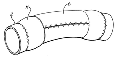
本発明者らは、弾性膜巻きつけ治療による大動脈の弾性増加を評価するため、ヒツジ5匹の下行大動脈に対してインビボ試験を行った。注意すべき点として、ヒツジの下行大動脈はヒトの下行大動脈よりやや小さい。大動脈の拡張および硬化した部分を模するため、図13に示すように、22 mm織物ポリエステル(Dacron)を材料とする大動脈グラフト11を大動脈2の切除部位に吻合した。グラフト11のDacron材料は実際の大動脈組成と比較して硬く且つ直径が大きいため、このグラフトにより、硬化および拡張した大動脈を模することができた。このDacronグラフトに、前述と同様に弾性膜6を巻きつけた。Dacronグラフト11の直径を制限するため、直径18 mmおよび20 mm(負荷がない状態)に巻いた膜6を使用した。大動脈の剛性を、切除前(基準値)、Dacronグラフト11の吻合後、および弾性膜6の巻きつけ後に測定した。測定にあたっては、前述と同様、生理学的な血流の脈圧範囲について圧力−ひずみ弾性率(Ep)を測定し、その平均値を用いた。
The present inventors conducted an in vivo study on the descending aorta of 5 sheep to evaluate the increase in elasticity of the aorta by elastic membrane wrapping treatment. It should be noted that the descending aorta of sheep is slightly smaller than the descending aorta of humans. In order to simulate the dilated and hardened part of the aorta, an
測定は、低い脈圧(正常血圧のシミュレーション)および高い脈圧(高血圧のシミュレーション)の両方について行った。高血圧はアラミンの注入によって誘発した。 Measurements were made for both low pulse pressure (simulation of normal blood pressure) and high pulse pressure (simulation of hypertension). Hypertension was induced by infusion of alamin.
予測されたとおり、Dagronグラフトの吻合によって弾性率が上昇した。上昇の程度は、基準となる健康な大動脈と比較して正常血圧では約11倍、高血圧では16倍であった。弾性膜を巻きつけることにより、大動脈の弾性率が正常血圧においては約4分の1、高血圧においては8分の1に低下し、弾性率の値は、基準となる健康な大動脈と比較して正常血圧では約2倍、高血圧では3倍となった。 As expected, the elastic modulus was increased by Dagron graft anastomosis. The degree of elevation was approximately 11 times for normal blood pressure and 16 times for hypertension compared to the reference healthy aorta. By wrapping the elastic membrane, the elastic modulus of the aorta is reduced to about 1/4 in normal blood pressure and 1/8 in high blood pressure, and the value of elastic modulus is compared to the healthy reference aorta The normal blood pressure was approximately doubled and the hypertension was tripled.
ヒト上行大動脈のサンプル8つを用いたインビトロ試験も行った。この試験では、上行大動脈のサンプル内で生理学的な脈圧を生じるため、プログラム可能なギアポンプを使用した。死体(年齢72〜91歳、一部は心臓関連の原因により死亡)から上行大動脈のサンプルを得た。これらの大動脈を試験した結果、大動脈の硬化および拡張の程度はさまざまであり、85/60 mmHg(11/8 kPa)という低い脈圧に対する圧力−ひずみ弾性率(Ep)の平均値は2.6〜13.3 x 10⁶ dyn/cm2(260〜1330 kPa)であった。収縮期高血圧を模した160/90 mmHg(21/12 kPa)という高い脈圧に対しては圧力−ひずみ弾性率の平均値が上昇し、約9.3〜21.8 x 10⁶ dyn/cm2(930〜2180 kPa)となった。 In vitro tests were also performed using 8 samples of human ascending aorta. In this study, a programmable gear pump was used to generate a physiological pulse pressure in the ascending aorta sample. Ascending aorta samples were obtained from corpses (age 72-91 years, some died from heart-related causes). As a result of testing these aorta, the degree of hardening and dilation of the aorta varied, and the average pressure-strain modulus (E p ) for pulse pressures as low as 85/60 mmHg (11/8 kPa) was 2.6- It was 13.3 × 10 6 dyn / cm 2 (260 to 1330 kPa). For pulse pressures as high as 160/90 mmHg (21/12 kPa) simulating systolic hypertension, the mean value of the pressure-strain elastic modulus increases, approximately 9.3 to 21.8 x 10 6 dyn / cm 2 (930 to 2180 kPa).
次に、前述のMedtronic製「コンプライアンス4%」膜および「コンプライアンス12%」膜(厚さ12.5 mm)を上行大動脈の各サンプルに巻きつけた。2種類の膜のそれぞれについて3つの異なる直径の膜を使用し、各大動脈サンプルについて合計6つの試験を行った。
Next, the aforementioned Medtronic “
巻きつけた膜の内径は、圧力範囲0〜220 mmHg(0〜29 kPa)に対する上行大動脈サンプルの平均外径のパーセンテージに基づいて選択した。選択したパーセンテージは、91%(D1、9%の直径減少に相当)、82%(D2)、および70%(D3)である。次に、負荷がかかっていない状態で所望の直径を得るために膜の端部のどこを縫合すべきかを示すため、前述と同様に膜シートにマーキングを施した。 The inner diameter of the wound membrane was selected based on the percentage of the average outer diameter of the ascending aorta sample for the pressure range 0-220 mmHg (0-29 kPa). The selected percentages are 91% (D1, corresponding to a 9% diameter reduction), 82% (D2), and 70% (D3). Next, the membrane sheet was marked in the same manner as described above in order to show where the end of the membrane should be stitched to obtain the desired diameter in the unloaded state.
各サンプルを包んだ後、自然状態の上行大動脈サンプルにおいて特定の拡張期血圧および収縮期血圧を生成させた際と同じポンプ設定を用いて、巻きつけを行った上行大動脈のサンプル内で脈圧を生成した。大動脈の直径、収縮期血圧、および拡張期血圧を測定した。 After wrapping each sample, the pulse pressure is measured within the wound ascending aorta sample using the same pump settings that generated specific diastolic and systolic blood pressures in the natural ascending aorta sample. Generated. Aortic diameter, systolic blood pressure, and diastolic blood pressure were measured.
膜材料(すなわち、コンプライアンス4%または12%)と非負荷時の膜の直径(すなわち、D1、D2、およびD3)との各組合せについて測定された大動脈サンプルの拡張時直径の平均値を、自然状態の大動脈の拡張時直径に対するパーセンテージ(D/D0)として計算し、この結果を表1にまとめた。
The mean value of the expanded diameter of the aortic sample measured for each combination of membrane material (
膜のコンプライアンスおよび直径のすべての組合せについて、試験した脈圧の全範囲にわたって圧力−ひずみ弾性率(Ep)の平均値が有意に低下した。表2に、膜の各構成について、より高い脈圧である160/90 mmHg(21/12 kPa)に対する各サンプルの圧力−ひずみ弾性率の平均値を示す。圧力−ひずみ弾性率が最も大幅に(94%)低減したのは「コンプライアンス4%」と直径70%(D3)との組合せであった。図14に各サンプルの圧力−ひずみ弾性率の平均値をグラフとして示した。
For all combinations of membrane compliance and diameter, the mean value of pressure-strain modulus (E p ) was significantly reduced over the entire range of pulse pressures tested. Table 2 shows the average value of the pressure-strain elastic modulus of each sample with respect to 160/90 mmHg (21/12 kPa), which is a higher pulse pressure, for each configuration of the membrane. The combination of “
脈圧も有意に低下し、特に、より剛性の高い「コンプライアンス4%」の場合および膜の直径がより小さい場合にこの傾向が強かった。さらに、拡張期血圧が上昇したことから冠灌流量も増加することが示唆され、したがって、この膜巻きつけ法が心不全の治療に好適であることが確認された。収縮期血圧の低下もみられたことから、心臓負荷が軽減すると考えられ、この方法が孤立性収縮期高血圧の治療に好適であることが示唆された。
The pulse pressure also decreased significantly, especially in the more rigid “
表3に、膜の各構成について、より高い脈圧である160/90 mmHg(21/12 kPa)に対する各サンプルの脈圧、拡張期血圧、および収縮期血圧の平均値を示す。上記と同様、最も良好な結果が得られたのは「コンプライアンス4%」と直径70%(D3)との組合せであり、脈圧は23%低下、拡張期血圧は10%上昇、収縮期血圧は3.4%低下した。図15〜17に各サンプルの脈圧、拡張期血圧、および収縮期血圧の測定結果をグラフとして示した。
Table 3 shows the average values of the pulse pressure, diastolic blood pressure, and systolic blood pressure of each sample with respect to the higher pulse pressure of 160/90 mmHg (21/12 kPa) for each configuration of the membrane. As above, the best results were obtained with the combination of “
上行大動脈の剛性および直径の変化を模するため、コンピュータによる動脈分枝モデルも使用した。このシミュレーションでは、上行大動脈の剛性および直径の変化の配列について、脈圧変化の予測値を計算した。このモデルは、自然状態の大動脈にかかる負荷が部分的なものとなるように弾性膜が自然状態の大動脈組織を制限している限り上行大動脈の有効剛性は主として弾性膜の剛性によって決定されるという事実に基づいており、前述のように弾性膜で包んだ上行大動脈を正確にシミュレーションすると考えられる。シミュレーション結果を基準剛性(E0)および基準直径(D0)に対して正規化し、脈圧(PP)を剛性E0・直径D0における基準脈圧(PP0)で割ったパーセンテージ(%)として表4にまとめた。さらに、シミュレーション結果を図18〜21のグラフにも示した。図18は、脈圧(PP)を剛性E0・直径D0における脈圧(PP0)に対して正規化した結果を示した表面プロットである。図19は直径平面(D)にデータを投影した二次元投影図、図20および図21は剛性平面(E)にデータを投影した投影図である。 A computerized arterial branch model was also used to simulate changes in stiffness and diameter of the ascending aorta. In this simulation, the predicted value of pulse pressure change was calculated for an array of changes in stiffness and diameter of the ascending aorta. In this model, the effective stiffness of the ascending aorta is mainly determined by the stiffness of the elastic membrane as long as the elastic membrane restricts the natural aortic tissue so that the load on the natural aorta is partial. Based on the fact, it is considered that the ascending aorta wrapped with the elastic membrane as described above is accurately simulated. The simulation result is normalized with respect to the reference stiffness (E 0 ) and the reference diameter (D 0 ), and the pulse pressure (PP) divided by the reference pulse pressure (PP 0 ) at the stiffness E 0 and the diameter D 0 (%) Are summarized in Table 4. Furthermore, the simulation results are also shown in the graphs of FIGS. FIG. 18 is a surface plot showing the result of normalizing the pulse pressure (PP) to the pulse pressure (PP 0 ) at the stiffness E 0 and the diameter D 0 . FIG. 19 is a two-dimensional projection diagram in which data is projected onto the diameter plane (D), and FIGS. 20 and 21 are projection diagrams in which data is projected onto the rigid plane (E).
ヒトのインビトロ試験で得られた個々の結果を比較するとコンピュータによる予測と良好に相関する。したがって、膜の剛性および巻きつけ時の直径が与えられたとき、このコンピュータモデルを用いてその影響を調べ、脈圧、ひいては左心室に対する動的負荷を所望の程度まで低減させることが可能である。 Comparison of individual results obtained in human in vitro tests correlates well with computer predictions. Therefore, given the stiffness of the membrane and the diameter at the time of wrapping, it is possible to examine the effect using this computer model and reduce the pulse pressure and thus the dynamic load on the left ventricle to the desired degree. .
コンピュータシミュレーションの結果が示しているように、剛性(E)を一定にして血管の直径(D)を小さくすると、血液が通過できる血管内の流路が小さくなることによって、脈圧(PP)はむしろ上昇する。直径(D)を一定にして剛性(E)を小さくすると脈圧(PP)は低下する。 As the result of computer simulation shows, when the stiffness (E) is kept constant and the diameter (D) of the blood vessel is reduced, the flow path in the blood vessel through which the blood can pass becomes smaller. Rather it rises. When the diameter (D) is kept constant and the stiffness (E) is reduced, the pulse pressure (PP) decreases.
直径を小さくすることそれ自体は脈圧を上昇させ、したがって直径を小さくすることは避けるべきであるとも示唆されるが、血管の有効剛性を自然状態の組織の値から弾性膜の剛性に近い値へと低下させるには、弾性膜を巻きつける際に直径を小さくする必要がある。剛性の有意な低下が得られれば、剛性の低下による脈圧の低下が直径の縮小による脈圧の上昇を大きく上回ることになる。このように、直径の縮小については、ある低い剛性を有する弾性膜が拡張期血圧から収縮期血圧までの圧力負荷の大部分を担えるようにするための十分な縮小度と、血流を制限しすぎない程度の縮小度との間のバランスが存在する。 It is suggested that reducing the diameter itself increases the pulse pressure, and therefore reducing the diameter should be avoided, but the effective stiffness of the blood vessel is a value close to that of the elastic membrane from the value of the tissue in the natural state. In order to decrease the diameter, it is necessary to reduce the diameter when the elastic film is wound. If a significant decrease in rigidity is obtained, the decrease in pulse pressure due to the decrease in rigidity greatly exceeds the increase in pulse pressure due to the reduction in diameter. Thus, with respect to the diameter reduction, the elastic membrane having a certain low rigidity can restrict the blood flow with sufficient degree of reduction so that it can carry most of the pressure load from the diastolic blood pressure to the systolic blood pressure. There is a balance between the degree of reduction that is not too much.
弾性膜の剛性と血管径の縮小度との理想的な組合せは具体的な用途によって異なるが、自然状態の血管の剛性はこの選択にほとんど影響しないと考えられる。 The ideal combination of elastic membrane stiffness and vessel diameter reduction varies with the specific application, but the natural vessel stiffness is considered to have little effect on this choice.
インビトロ試験およびコンピュータシミュレーションによる結果から、拡張期の血管の直径を10〜15%小さくすることが特に好適であると考えられる。上行大動脈では、正常拡張期血圧70 mmHg(9 kPa)に対する外径を18 mm〜30mmまで縮小することが特に好適であり、血流を制限しすぎて悪影響を及ぼすこともないと考えられる。若年者の場合、上行大動脈の拡張期の外径を10 mmまで縮小することが特に好適である。 From the results of in vitro tests and computer simulations, it is considered particularly suitable to reduce the diameter of the diastolic blood vessel by 10 to 15%. In the ascending aorta, it is particularly preferable to reduce the outer diameter with respect to the normal diastolic blood pressure of 70 mmHg (9 kPa) to 18 mm to 30 mm, and it is considered that the blood flow is too restricted to have an adverse effect. In the case of young people, it is particularly preferable to reduce the diastolic outer diameter of the ascending aorta to 10 mm.
大動脈(特に上行大動脈)の治療においては、弾性膜の引張剛性×膜厚の値を25〜2500 N/mとすることも好適であると考えられ、50〜1000 N/mとすることは特に好適であると考えられる。 In the treatment of the aorta (especially the ascending aorta), it is considered suitable that the value of the tensile stiffness of the elastic membrane × the thickness is 25 to 2500 N / m, especially 50 to 1000 N / m It is considered preferable.
膜自体の圧力−ひずみ弾性率の平均値については、内径20 mmの円筒形にした膜の場合、脈圧120/70 mmHg(16/9 kPa)に対する弾性率を0.15 x 10⁶〜15 x 106 dyn/cm2とすることが好適であると考えられ、0.3 x 106〜6 x 10⁶ dyn/cm2とすることは特に好適であると考えられる。 For the average value of pressure-strain elastic modulus of the membrane itself, in the case of a cylindrical membrane with an inner diameter of 20 mm, the elastic modulus for a pulse pressure of 120/70 mmHg (16/9 kPa) is 0.15 x 10 6 to 15 x 10 6 dyn / cm 2 is considered suitable, and 0.3 x 10 6 to 6 x 10 6 dyn / cm 2 is considered particularly suitable.
コンピュータモデルから、弾性膜で血管を包む方法は上行大動脈に用いた場合に最も効果が高いことも明らかになった。硬化した他の血管(特に大動脈の他の部分)を包むことでも改善は得られるが、上行大動脈を包んだ場合と比較して脈圧の低下度が非常に小さい。上行大動脈には肋間動脈の分枝がないという特徴もあり、したがって1枚の膜シートで容易に包めるため、手術の単純性という意味においても包むのに非常に適した血管である。さらに、コンピュータモデルから、上行大動脈および近位大動脈弓のみを包む場合と比較して、大動脈の他の部分を包むことにより増える利点はほとんどないことも示された。 The computer model also revealed that the method of wrapping blood vessels with an elastic membrane is most effective when used in the ascending aorta. Wrapping other hardened blood vessels (especially other parts of the aorta) can also improve, but the degree of decrease in pulse pressure is very small compared to wrapping the ascending aorta. The ascending aorta is also characterized by the absence of intercostal artery branching, and is therefore a very suitable blood vessel for wrapping in terms of simplicity of operation because it can be easily wrapped with a single membrane sheet. In addition, computer models have shown that there is little benefit to enveloping other parts of the aorta compared to wrapping only the ascending aorta and proximal aortic arch.
本明細書に説明した方法は、拡張を伴うか否かに関わらず種々の機序によって硬化した自然状態の血管の治療に利用できるが、そのほかにも、自然状態の血管に合成血管を移植することによって硬化した血管の治療にも利用できる。そうしたグラフトは、通常、順応性を有しない織物ポリエステル材料(Dacronなど)で形成され、損傷した大動脈部分の置換、特に動脈瘤の除去を目的として使用されることが多い。ポリテトラフルオロエチレン(PTFE)またはGore-Tex(登録商標)など、そのほかのグラフトも同様に治療してよい。前述のヒツジインビボ試験で示したように、順応性を有しないグラフトを使用することによって血管の剛性が大幅に上昇するが、前述の様式でグラフトに弾性膜を巻きつけることによってこれを好適に治療することが可能である。 The methods described herein can be used to treat native blood vessels that have hardened by a variety of mechanisms, whether or not they involve dilatation, but in addition, grafting synthetic blood vessels into native blood vessels It can also be used for treatment of cured blood vessels. Such grafts are usually made of a non-compliant woven polyester material (such as Dacron) and are often used to replace damaged aortic parts, particularly to remove aneurysms. Other grafts such as polytetrafluoroethylene (PTFE) or Gore-Tex® may be treated as well. As shown in the aforementioned sheep in vivo test, the use of a non-compliant graft significantly increases the rigidity of the blood vessel, but this is preferably treated by wrapping an elastic membrane around the graft in the manner described above. Is possible.
前述の方法は単独の手技として実施してもよく、または、薬物療法もしくは作用物療法(薬理学的療法、細胞療法、遺伝子療法、その他の療法)と併用してもよい。さらに、弾性膜を治療対象血管に巻きつける前に弾性膜の内部または表面にそのような薬物または作用物を組み込み、これにより薬物または作用物の直接送達を実現してもよい。本発明の方法はヒトおよび動物のいずれにも適用可能である。本明細書に説明した方法は、使用が簡単であり、且つ、膜が血管の外側に用いられる血液非接触型の装置であり且つ受動的な装置であることから他の種々の周知の治療法と比較して合併症を起こす可能性が小さい。 The foregoing methods may be performed as a single procedure or may be combined with drug therapy or agent therapy (pharmacological therapy, cell therapy, gene therapy, other therapy). Further, such drugs or agents may be incorporated within or on the elastic membrane prior to wrapping the elastic membrane around the vessel to be treated, thereby achieving direct delivery of the drug or agent. The method of the present invention can be applied to both humans and animals. The method described herein is simple to use and various other well known treatments because the membrane is a non-blood contact device used outside the blood vessel and is a passive device. Compared with, there is less chance of complications.
(表1)種々の膜構成に対する大動脈の拡張時直径の平均値

(表2)種々の膜構成に対する圧力−ひずみ弾性率の平均値
(表3)種々の膜構成に対する脈圧、拡張期血圧、および収縮期血圧の平均値
(表4)種々の半径および弾性率に対するPP/PP0(%)の推定値
以下に、本発明の好ましい態様を添付の図面を参照しながら例として説明する。
Claims (36)
Applications Claiming Priority (2)
| Application Number | Priority Date | Filing Date | Title |
|---|---|---|---|
| AU2002953440A AU2002953440A0 (en) | 2002-12-19 | 2002-12-19 | A method of treating a stiffened vessel |
| PCT/AU2003/001699 WO2004056274A1 (en) | 2002-12-19 | 2003-12-19 | A method of treating a stiffened blood vessel |
Publications (2)
| Publication Number | Publication Date |
|---|---|
| JP2006510417A JP2006510417A (en) | 2006-03-30 |
| JP4373337B2 true JP4373337B2 (en) | 2009-11-25 |
Family
ID=30004525
Family Applications (1)
| Application Number | Title | Priority Date | Filing Date |
|---|---|---|---|
| JP2004560914A Expired - Fee Related JP4373337B2 (en) | 2002-12-19 | 2003-12-19 | Cured blood vessel treatment method |
Country Status (6)
| Country | Link |
|---|---|
| US (1) | US7981103B2 (en) |
| EP (1) | EP1578285A4 (en) |
| JP (1) | JP4373337B2 (en) |
| AU (1) | AU2002953440A0 (en) |
| CA (1) | CA2510450A1 (en) |
| WO (1) | WO2004056274A1 (en) |
Families Citing this family (29)
| Publication number | Priority date | Publication date | Assignee | Title |
|---|---|---|---|---|
| AUPQ090499A0 (en) | 1999-06-10 | 1999-07-01 | Peters, William S | Heart assist device and system |
| AUPR669001A0 (en) | 2001-07-30 | 2001-08-23 | Sunshine Heart Company Pty Ltd | A fluid pressure generating means |
| AU2002952691A0 (en) * | 2002-11-15 | 2002-11-28 | Sunshine Heart Company Pty Ltd | Heart assist device utilising aortic deformation |
| ATE531338T1 (en) * | 2003-04-28 | 2011-11-15 | Kips Bay Medical Inc | ELASTIC VENOUS IMPLANT |
| US20050131520A1 (en) * | 2003-04-28 | 2005-06-16 | Zilla Peter P. | Compliant blood vessel graft |
| US7998188B2 (en) * | 2003-04-28 | 2011-08-16 | Kips Bay Medical, Inc. | Compliant blood vessel graft |
| US7862499B2 (en) * | 2003-10-30 | 2011-01-04 | Sunshine Heart Company Pty Ltd | Blood vessel wrap |
| WO2005042082A1 (en) | 2003-10-31 | 2005-05-12 | Sunshine Heart Company Pty Ltd | Percutaneous gas-line |
| EP3028739A1 (en) * | 2003-10-31 | 2016-06-08 | Sunshine Heart Company Pty Ltd | Synchronisation control system |
| CN1878581B (en) * | 2003-11-11 | 2010-07-07 | 阳光心脏有限公司 | Actuator for a heart assist device |
| DE10355986A1 (en) * | 2003-11-27 | 2005-06-30 | Forschungszentrum Karlsruhe Gmbh | compression sleeve |
| CA2599434C (en) | 2004-03-02 | 2016-09-13 | Peter William Walsh | A vessel or sac wall treatment and a cardiac assist device |
| EP2054103B1 (en) | 2006-08-21 | 2019-05-29 | Sunshine Heart Company Pty Ltd | An improved wrap for a heart assist device |
| US20110288625A1 (en) * | 2008-10-30 | 2011-11-24 | Macquarie University | Vessel Support Device and Methods for Supporting a Vessel |
| ES2793478T3 (en) * | 2010-03-09 | 2020-11-16 | Solinas Medical Inc | Automatic closing devices |
| US20110270331A1 (en) | 2010-04-02 | 2011-11-03 | Sunshine Heart Company Pty Ltd | Combination heart assist systems, methods, and devices |
| US9125655B2 (en) * | 2010-07-16 | 2015-09-08 | California Institute Of Technology | Correction and optimization of wave reflection in blood vessels |
| GB201019354D0 (en) * | 2010-11-16 | 2010-12-29 | Vascutek Ltd | Prothesis |
| US9433722B2 (en) * | 2011-08-09 | 2016-09-06 | Abbott Cardiovascular Systems Inc. | Vascular shield and delivery system |
| AU2012216373B2 (en) * | 2011-08-29 | 2013-09-19 | Aortic Wrap Pty Ltd | A method and device for treating a stiffened blood vessel |
| US9526503B2 (en) * | 2013-08-12 | 2016-12-27 | W. L. Gore & Associates, Inc. | Lumbar ostia occlusion devices and methods of deploying the same |
| US20170042551A1 (en) * | 2015-08-13 | 2017-02-16 | The Brain Protection Company PTY LTD | Implantable damping devices for treating dementia and associated systems and methods of use |
| JP6711486B2 (en) * | 2016-07-04 | 2020-06-17 | 泉工医科工業株式会社 | Blood vessel sewing member and blood vessel sewing apparatus |
| JP2021501662A (en) * | 2017-11-03 | 2021-01-21 | ザ ブレイン プロテクション カンパニー ピーティーワイ リミテッド | Implantable damping device to modify blood flow characteristics |
| US20220022881A1 (en) * | 2018-12-04 | 2022-01-27 | The Brain Protection Company PTY LTD | Combinatorial therapies including implantable damping devices and therapeutic agents for treating a condition and associated systems and methods of use |
| RU195850U1 (en) * | 2019-11-26 | 2020-02-06 | Федеральное государственное бюджетное образовательное учреждение высшего образования "Кемеровский государственный медицинский университет" ФГБОУ ВО"КемГМУ" | Device for emergency stop bleeding of parenchymal organs |
| RU195669U1 (en) * | 2019-11-27 | 2020-02-03 | Федеральное государственное бюджетное образовательное учреждение высшего образования "Кемеровский государственный медицинский университет" ФГБОУ ВО "КемГМУ" | Device for emergency stop bleeding of parenchymal organs |
| US20240108348A1 (en) * | 2019-12-16 | 2024-04-04 | The Brain Protection Company PTY LTD | Device and method for altering blood flow characteristics in a vessel |
| JP7100396B1 (en) | 2021-06-28 | 2022-07-13 | 真一 岩越 | Aortic reinforcement |
Family Cites Families (19)
| Publication number | Priority date | Publication date | Assignee | Title |
|---|---|---|---|---|
| US3726279A (en) * | 1970-10-08 | 1973-04-10 | Carolina Medical Electronics I | Hemostatic vascular cuff |
| SU566567A1 (en) * | 1974-07-15 | 1977-07-30 | Киевский Медицинский Институт Им. Академика А.А.Богомольца | Method of treating aneurismus of blood vessels |
| US4202349A (en) * | 1978-04-24 | 1980-05-13 | Jones James W | Radiopaque vessel markers |
| US4834755A (en) * | 1983-04-04 | 1989-05-30 | Pfizer Hospital Products Group, Inc. | Triaxially-braided fabric prosthesis |
| US5057118A (en) * | 1990-05-29 | 1991-10-15 | Applied Medical Technology, Inc. | Vessel occlusion device |
| US5304200A (en) * | 1991-05-29 | 1994-04-19 | Cordis Corporation | Welded radially expandable endoprosthesis and the like |
| US5314472A (en) * | 1991-10-01 | 1994-05-24 | Cook Incorporated | Vascular stent |
| US5387235A (en) * | 1991-10-25 | 1995-02-07 | Cook Incorporated | Expandable transluminal graft prosthesis for repair of aneurysm |
| GB9424162D0 (en) * | 1994-11-30 | 1995-01-18 | Cookson Group Plc | Metallization of phosphor screens |
| AU739710B2 (en) * | 1996-08-23 | 2001-10-18 | Boston Scientific Limited | Stent delivery system having stent securement apparatus |
| DE19822157B4 (en) * | 1998-05-16 | 2013-01-10 | Abbott Laboratories Vascular Enterprises Ltd. | Radially expandable stent for implantation in a body vessel |
| MXPA02003066A (en) | 1999-09-22 | 2003-09-05 | Impra Inc | Radioactive graft or cuff. |
| GB0023412D0 (en) * | 2000-09-23 | 2000-11-08 | Khaghani Asghar | Aortic counterpulsator |
| US7499742B2 (en) * | 2001-09-26 | 2009-03-03 | Cvrx, Inc. | Electrode structures and methods for their use in cardiovascular reflex control |
| US7008436B2 (en) * | 2000-12-08 | 2006-03-07 | Peter Barath | Method and coupling apparatus for facilitating an vascular anastomoses |
| DE60237671D1 (en) * | 2001-01-16 | 2010-10-28 | Vascular Therapies Llc | IMPLANTABLE DEVICE CONTAINING RESORBABLE MATRIX MATERIALS AND ANTIPROLIFERATIVE ACTIVE SUBSTANCES FOR PREVENTING OR TREATING FAILURE OF VASCULAR HEMODIALYSIS ACCUMULATIONS AND OTHER VASCULAR TRANSPLANTS |
| DE10137414B4 (en) * | 2001-07-31 | 2005-12-29 | Aesculap Ag & Co. Kg | Sheath for veins and use in surgery |
| US6808518B2 (en) * | 2001-09-28 | 2004-10-26 | Ethicon, Inc. | Methods and devices for treating diseased blood vessels |
| WO2004037152A2 (en) * | 2002-10-07 | 2004-05-06 | Pavad Medical, Inc. | Vascular assist device and methods |
-
2002
- 2002-12-19 AU AU2002953440A patent/AU2002953440A0/en not_active Abandoned
-
2003
- 2003-12-19 US US10/540,306 patent/US7981103B2/en not_active Expired - Fee Related
- 2003-12-19 WO PCT/AU2003/001699 patent/WO2004056274A1/en active Application Filing
- 2003-12-19 EP EP03767299A patent/EP1578285A4/en not_active Withdrawn
- 2003-12-19 CA CA002510450A patent/CA2510450A1/en not_active Abandoned
- 2003-12-19 JP JP2004560914A patent/JP4373337B2/en not_active Expired - Fee Related
Also Published As
| Publication number | Publication date |
|---|---|
| EP1578285A4 (en) | 2009-04-08 |
| JP2006510417A (en) | 2006-03-30 |
| US20060052866A1 (en) | 2006-03-09 |
| CA2510450A1 (en) | 2004-07-08 |
| US7981103B2 (en) | 2011-07-19 |
| WO2004056274A1 (en) | 2004-07-08 |
| EP1578285A1 (en) | 2005-09-28 |
| AU2002953440A0 (en) | 2003-01-09 |
Similar Documents
| Publication | Publication Date | Title |
|---|---|---|
| JP4373337B2 (en) | Cured blood vessel treatment method | |
| US10595868B2 (en) | Graft apparatus | |
| EP0329765B1 (en) | Prosthetic compliance devices | |
| Duerig et al. | An overview of nitinol medical applications | |
| US20120029266A1 (en) | Anisotropic reinforcement and related method thereof | |
| Nappi et al. | Compliance mismatch and compressive wall stresses drive anomalous remodelling of pulmonary trunks reinforced with Dacron grafts | |
| Yoffe et al. | Experimental study of a novel suture-less aortic anastomotic device | |
| US20130102835A1 (en) | Anisotropic reinforcement and related method thereof | |
| AU2003291841B2 (en) | A method of treating a stiffened blood vessel | |
| AU2012216373B2 (en) | A method and device for treating a stiffened blood vessel | |
| EP1874194A2 (en) | Method and extravenous corrector for simultaneous repair of multiple incompetent venous valves | |
| May-Newman | Mechanical Effects of Cardiovascular Drugs and Devices | |
| Izadian | THE UNIVERSITY OF HULL | |
| Thubrikar | The Vein Graft | |
| JP5323810B2 (en) | Surgical kit having vascular connector and applicator | |
| Desai | Development of endovascular stent-grafts based on a nanocomposite polymer | |
| Tabayashi et al. | General Session “Cardiopulmonary-Clinical 1” | |
| Grigioni et al. | E DIASTAT VASCULAR ACCEss GRAT pop | |
| WO2016038587A1 (en) | Superficial adventitial aortaplasty |
Legal Events
| Date | Code | Title | Description |
|---|---|---|---|
| A521 | Request for written amendment filed |
Free format text: JAPANESE INTERMEDIATE CODE: A523 Effective date: 20060906 |
|
| A621 | Written request for application examination |
Free format text: JAPANESE INTERMEDIATE CODE: A621 Effective date: 20061219 |
|
| A131 | Notification of reasons for refusal |
Free format text: JAPANESE INTERMEDIATE CODE: A131 Effective date: 20090508 |
|
| A521 | Request for written amendment filed |
Free format text: JAPANESE INTERMEDIATE CODE: A523 Effective date: 20090803 |
|
| TRDD | Decision of grant or rejection written | ||
| A01 | Written decision to grant a patent or to grant a registration (utility model) |
Free format text: JAPANESE INTERMEDIATE CODE: A01 Effective date: 20090826 |
|
| A01 | Written decision to grant a patent or to grant a registration (utility model) |
Free format text: JAPANESE INTERMEDIATE CODE: A01 |
|
| A61 | First payment of annual fees (during grant procedure) |
Free format text: JAPANESE INTERMEDIATE CODE: A61 Effective date: 20090903 |
|
| FPAY | Renewal fee payment (event date is renewal date of database) |
Free format text: PAYMENT UNTIL: 20120911 Year of fee payment: 3 |
|
| R150 | Certificate of patent or registration of utility model |
Ref document number: 4373337 Country of ref document: JP Free format text: JAPANESE INTERMEDIATE CODE: R150 Free format text: JAPANESE INTERMEDIATE CODE: R150 |
|
| S111 | Request for change of ownership or part of ownership |
Free format text: JAPANESE INTERMEDIATE CODE: R313113 |
|
| FPAY | Renewal fee payment (event date is renewal date of database) |
Free format text: PAYMENT UNTIL: 20120911 Year of fee payment: 3 |
|
| R350 | Written notification of registration of transfer |
Free format text: JAPANESE INTERMEDIATE CODE: R350 |
|
| FPAY | Renewal fee payment (event date is renewal date of database) |
Free format text: PAYMENT UNTIL: 20130911 Year of fee payment: 4 |
|
| R250 | Receipt of annual fees |
Free format text: JAPANESE INTERMEDIATE CODE: R250 |
|
| R250 | Receipt of annual fees |
Free format text: JAPANESE INTERMEDIATE CODE: R250 |
|
| R250 | Receipt of annual fees |
Free format text: JAPANESE INTERMEDIATE CODE: R250 |
|
| R250 | Receipt of annual fees |
Free format text: JAPANESE INTERMEDIATE CODE: R250 |
|
| R250 | Receipt of annual fees |
Free format text: JAPANESE INTERMEDIATE CODE: R250 |
|
| R250 | Receipt of annual fees |
Free format text: JAPANESE INTERMEDIATE CODE: R250 |
|
| R250 | Receipt of annual fees |
Free format text: JAPANESE INTERMEDIATE CODE: R250 |
|
| R250 | Receipt of annual fees |
Free format text: JAPANESE INTERMEDIATE CODE: R250 |
|
| R250 | Receipt of annual fees |
Free format text: JAPANESE INTERMEDIATE CODE: R250 |
|
| LAPS | Cancellation because of no payment of annual fees |