JP4372401B2 - Correction characteristic determination device, correction characteristic determination method, and display device - Google Patents
Correction characteristic determination device, correction characteristic determination method, and display device Download PDFInfo
- Publication number
- JP4372401B2 JP4372401B2 JP2002268599A JP2002268599A JP4372401B2 JP 4372401 B2 JP4372401 B2 JP 4372401B2 JP 2002268599 A JP2002268599 A JP 2002268599A JP 2002268599 A JP2002268599 A JP 2002268599A JP 4372401 B2 JP4372401 B2 JP 4372401B2
- Authority
- JP
- Japan
- Prior art keywords
- gradation
- correction
- value
- target
- matrix
- Prior art date
- Legal status (The legal status is an assumption and is not a legal conclusion. Google has not performed a legal analysis and makes no representation as to the accuracy of the status listed.)
- Expired - Fee Related
Links
- 238000012937 correction Methods 0.000 title claims description 471
- 238000000034 method Methods 0.000 title claims description 127
- 235000019557 luminance Nutrition 0.000 claims description 276
- 239000011159 matrix material Substances 0.000 claims description 212
- 238000006243 chemical reaction Methods 0.000 claims description 201
- 230000008569 process Effects 0.000 claims description 65
- 238000005259 measurement Methods 0.000 claims description 59
- 239000000203 mixture Substances 0.000 claims description 43
- 230000008859 change Effects 0.000 claims description 42
- 239000003086 colorant Substances 0.000 claims description 26
- 230000009466 transformation Effects 0.000 claims description 6
- 239000004973 liquid crystal related substance Substances 0.000 description 100
- 238000010586 diagram Methods 0.000 description 14
- 238000005070 sampling Methods 0.000 description 13
- 230000007704 transition Effects 0.000 description 11
- 230000002093 peripheral effect Effects 0.000 description 4
- 239000000047 product Substances 0.000 description 4
- 230000000694 effects Effects 0.000 description 3
- 238000002834 transmittance Methods 0.000 description 2
- 230000007423 decrease Effects 0.000 description 1
- 230000002950 deficient Effects 0.000 description 1
- 238000005401 electroluminescence Methods 0.000 description 1
- 238000005516 engineering process Methods 0.000 description 1
- 230000006870 function Effects 0.000 description 1
- 238000005286 illumination Methods 0.000 description 1
- 230000001788 irregular Effects 0.000 description 1
- 239000013589 supplement Substances 0.000 description 1
- 230000001131 transforming effect Effects 0.000 description 1
Images


Classifications
-
- G—PHYSICS
- G02—OPTICS
- G02F—OPTICAL DEVICES OR ARRANGEMENTS FOR THE CONTROL OF LIGHT BY MODIFICATION OF THE OPTICAL PROPERTIES OF THE MEDIA OF THE ELEMENTS INVOLVED THEREIN; NON-LINEAR OPTICS; FREQUENCY-CHANGING OF LIGHT; OPTICAL LOGIC ELEMENTS; OPTICAL ANALOGUE/DIGITAL CONVERTERS
- G02F1/00—Devices or arrangements for the control of the intensity, colour, phase, polarisation or direction of light arriving from an independent light source, e.g. switching, gating or modulating; Non-linear optics
- G02F1/01—Devices or arrangements for the control of the intensity, colour, phase, polarisation or direction of light arriving from an independent light source, e.g. switching, gating or modulating; Non-linear optics for the control of the intensity, phase, polarisation or colour
- G02F1/13—Devices or arrangements for the control of the intensity, colour, phase, polarisation or direction of light arriving from an independent light source, e.g. switching, gating or modulating; Non-linear optics for the control of the intensity, phase, polarisation or colour based on liquid crystals, e.g. single liquid crystal display cells
- G02F1/133—Constructional arrangements; Operation of liquid crystal cells; Circuit arrangements
-
- G—PHYSICS
- G09—EDUCATION; CRYPTOGRAPHY; DISPLAY; ADVERTISING; SEALS
- G09G—ARRANGEMENTS OR CIRCUITS FOR CONTROL OF INDICATING DEVICES USING STATIC MEANS TO PRESENT VARIABLE INFORMATION
- G09G3/00—Control arrangements or circuits, of interest only in connection with visual indicators other than cathode-ray tubes
- G09G3/006—Electronic inspection or testing of displays and display drivers, e.g. of LED or LCD displays
-
- G—PHYSICS
- G09—EDUCATION; CRYPTOGRAPHY; DISPLAY; ADVERTISING; SEALS
- G09G—ARRANGEMENTS OR CIRCUITS FOR CONTROL OF INDICATING DEVICES USING STATIC MEANS TO PRESENT VARIABLE INFORMATION
- G09G3/00—Control arrangements or circuits, of interest only in connection with visual indicators other than cathode-ray tubes
- G09G3/20—Control arrangements or circuits, of interest only in connection with visual indicators other than cathode-ray tubes for presentation of an assembly of a number of characters, e.g. a page, by composing the assembly by combination of individual elements arranged in a matrix no fixed position being assigned to or needed to be assigned to the individual characters or partial characters
- G09G3/34—Control arrangements or circuits, of interest only in connection with visual indicators other than cathode-ray tubes for presentation of an assembly of a number of characters, e.g. a page, by composing the assembly by combination of individual elements arranged in a matrix no fixed position being assigned to or needed to be assigned to the individual characters or partial characters by control of light from an independent source
- G09G3/36—Control arrangements or circuits, of interest only in connection with visual indicators other than cathode-ray tubes for presentation of an assembly of a number of characters, e.g. a page, by composing the assembly by combination of individual elements arranged in a matrix no fixed position being assigned to or needed to be assigned to the individual characters or partial characters by control of light from an independent source using liquid crystals
- G09G3/3611—Control of matrices with row and column drivers
-
- G—PHYSICS
- G09—EDUCATION; CRYPTOGRAPHY; DISPLAY; ADVERTISING; SEALS
- G09G—ARRANGEMENTS OR CIRCUITS FOR CONTROL OF INDICATING DEVICES USING STATIC MEANS TO PRESENT VARIABLE INFORMATION
- G09G2320/00—Control of display operating conditions
- G09G2320/02—Improving the quality of display appearance
- G09G2320/0271—Adjustment of the gradation levels within the range of the gradation scale, e.g. by redistribution or clipping
- G09G2320/0276—Adjustment of the gradation levels within the range of the gradation scale, e.g. by redistribution or clipping for the purpose of adaptation to the characteristics of a display device, i.e. gamma correction
Landscapes
- Engineering & Computer Science (AREA)
- Physics & Mathematics (AREA)
- General Physics & Mathematics (AREA)
- Theoretical Computer Science (AREA)
- Computer Hardware Design (AREA)
- Crystallography & Structural Chemistry (AREA)
- Chemical & Material Sciences (AREA)
- Nonlinear Science (AREA)
- Mathematical Physics (AREA)
- Optics & Photonics (AREA)
- Control Of Indicators Other Than Cathode Ray Tubes (AREA)
- Liquid Crystal Display Device Control (AREA)
- Image Processing (AREA)
- Controls And Circuits For Display Device (AREA)
Description
【0001】
【発明の属する技術分野】
本発明は、液晶パネル等の表示装置の表示品質を向上させるために映像信号に対して施される補正の補正特性を決定するための補正特性決定装置および補正特性決定方法、並びに補正特性決定方法にて補正特性が決定される表示装置に関するものである。
【0002】
【従来の技術】
近年、カラーの液晶表示装置(液晶カラーディスプレイ)が各種開発され、市販されている。液晶表示装置には、液晶パネルの表示品質を向上させるために、入力される映像信号にγ補正を施すγ補正装置が備えられている。そして、このγ補正の補正特性を適切に決定することができる補正特性決定装置が必要とされている。
【0003】
従来、液晶表示装置のγ補正に関する技術としては、特開平5−127620号公報に開示された技術がある。この公報に開示された技術は、投写型の液晶表示装置において、実際に投写した映像の輝度・色度を測定し、ホワイトバランスを目標色度に調整しつつγ補正を行う点が開示されている。
【0004】
【発明が解決しようとする課題】
ところが、上記特開平5−127620号公報に開示されている技術では、ホワイトバランスを調整する際に、予め設定された目標色度および実際に測定された色度からRGBの目標混合比を求めているが、RGBの目標混合比を求める演算において、個々の表示装置の特性が考慮されていない。より具体的には、上記公報に開示された技術では、RGBそれぞれの単色を投写した場合の色度を用いてRGBの目標混合比が算出されているが、白表示の場合の色度は考慮されていないため、実際の表示装置におけるRGB間での輝度のばらつき等が反映されずにRGBの目標混合比が算出されている。
【0005】
このため、上記公報に開示された技術では、補正後の表示装置による表示においても、個々の表示装置のばらつきに起因して、RGBの目標混合比から依然としてずれた状態になってしまう。
【0006】
また、上記公報に開示された技術では、低階調部において液晶素子の有する黒浮きの特性が考慮されていないため、後述する図10(a)のように目標値曲線(階調値に対する出力輝度の目標値を表す曲線)が、液晶素子に表示できない値となることがある。
【0007】
例えば、最低階調部において、目標値曲線が示す目標値は「0」であっても、その液晶素子に実際に最低階調を表示させ、そのときの輝度・色度を測定すると若干の輝度・色度がある場合がある。そのため、目標値「0」はその液晶素子には表示不可能な値であり、表示可能な目標値を設定するためには、低階調部において目標値を修正する必要がある。
【0008】
さらに、低階調部における目標値を修正した際に、図10(b)に示すように修正した低階調部の目標値から修正していない中〜高階調部の目標値への移行がスムーズに変化しない場合(図10(c)のような場合)、補正後の表示装置における表示においてその階調付近で輝度・色度が大きく変化し、品質の悪い映像になってしまうことがある。
【0009】
本発明は、このような従来技術の問題点に鑑みてなされたものであり、その目的は、映像信号に補正を施して表示手段に映像を表示する表示装置に対して、その補正特性を表示手段の特性にあったものとするための補正特性決定装置および補正特性決定方法を提供することにある。また、そのような補正特性決定方法により補正特性が決定された表示装置を提供することにある。
【0010】
【課題を解決するための手段】
本発明に係る補正特性決定装置は、三原色信号からなる映像信号に補正を施し、補正後の信号に基づいて表示手段にカラー映像を表示する表示装置における補正特性を決定する補正特性決定装置であって、上記の課題を解決するために、上記表示手段の表示における発光状態の測定結果を三刺激値に変換可能な値で示したデータである測定データを、変換行列を用いて上記三原色の輝度データに変換するデータ変換手段と、上記データ変換手段による変換結果に基づいて上記補正特性を決定する補正特性決定手段と、上記変換行列を生成する行列生成手段とを備え、上記行列生成手段は、上記表示手段が各原色の最高階調を表示したときの測定データに基づいて上記変換行列の逆行列の行列要素を生成する行列要素生成手段と、上記表示手段が白の最高階調を表示したときの測定データに基づいて上記行列要素生成手段により生成された行列要素を修正する行列要素修正手段と、上記修正された行列要素からなる行列の逆行列を生成する逆行列生成手段とを備えることを特徴としている。
【0011】
上記の構成では、測定データをデータ変換手段により三原色の輝度データに変換することで、その表示装置の表示手段の特性を三原色の輝度データにて把握することができる。補正特性決定手段では、この三原色輝度データに基づくことにより、所望とする補正特性を決定することができる。
【0012】
なお、測定データは、表示手段の表示における発光状態の測定結果を三刺激値に変換可能な値で示したデータであり、例えば輝度・色度計等の測定手段から得ることができる。また、「三刺激値に変換可能な値」とは、例えばXYZ表色系のX,Y,Zのように三刺激値そのものであってもよく、Yxy表色系のY,x,yのように三刺激値と相関がある値であってもよい。
【0013】
また、補正特性は、映像信号の階調値と、その階調値が表示装置に入力されたときに、表示手段における実際の出力輝度として適切な値(目標出力輝度)との関係として決定される。
【0014】
ここで、データ変換手段にてデータ変換に利用する変換行列は、行列生成手段により生成される。行列生成手段は、行列要素生成手段、行列要素修正手段および逆行列生成手段により変換行列を生成する。
【0015】
行列要素生成手段は、表示手段が各原色の最高階調を表示したときの測定データを用いて実施形態の式1が成り立つことから、変換行列の逆行列の行列要素を生成することができる。
【0016】
行列要素修正手段は、行列要素生成手段により生成された行列要素を用いて実施形態の式2を作成し、表示手段が白の最高階調を表示したときの測定データを式2に代入して式3とし、式3を解くことにより行列要素を表示手段の特性にあったものに修正することができる。
【0017】
逆行列生成手段は、行列要素修正手段にて修正された行列要素からなる行列の逆行列を生成することで変換行列を生成することができる。
【0018】
このように、行列生成手段が表示手段の特性にあった変換行列を生成することで、データ変換手段によるデータ変換を適正化することができる。その結果、データ変換の際のオーバーフローや変換誤差等を抑制することができ、補正特性決定手段による補正特性の決定をより正確にすることができるようになる。
【0019】
本発明に係る補正特性決定装置は、上記補正特性決定装置において、上記表示手段における表示の色度を設定するために目標となる色度を三刺激値に変換可能な値で示す目標色度データを、上記変換行列を用いて変換することで、三原色の出力輝度の混合比を生成する目標混合比生成手段を備え、上記補正特性決定手段は、上記表示手段が白の最高階調を表示したときの測定データを上記データ変換手段にて変換した結果と、上記目標混合比とに基づいて、上記映像信号における各原色信号の最高階調値に対応する目標出力輝度を決定する最高階調決定手段を備えることが望ましい。
【0020】
上記の構成では、目標混合比生成手段が、上記変換行列により目標色度データを三原色の輝度データに変換し、三原色の出力輝度の混合比を生成する。目標色度データは、例えば外部から本補正特性決定装置に対して入力されるものである。このように、表示手段の特性にあった変換行列を用いて目標色度データを変換することで、三原色の輝度データが本来の値からずれることを抑制し、三原色の出力輝度の正確な混合比を生成することができる。この混合比を用いて最高階調決定手段が映像信号における各原色信号の最高階調値に対応する目標出力輝度を決定することで、最高階調を正確な混合比に設定することができる。
【0021】
本発明に係る補正特性決定装置は、上記最高階調決定手段を備える補正特性決定装置において、上記最高階調決定手段は、上記表示手段が白の最高階調を表示したときの測定データを上記データ変換手段にて変換した結果における各原色の輝度データの比率と、上記目標混合比とに基づいて、輝度データが最も不足しているものをその原色信号の最高階調値に対応する目標出力輝度とし、この目標出力輝度を基準にして上記目標混合比に基づいて他の原色信号の最高階調値に対応する目標出力輝度を決定することが望ましい。
【0022】
上記の構成では、基準となる原色以外の原色の目標出力輝度が変換結果の輝度データ以下になる。したがって、何れの原色においても、表示手段にて実際に表示できない輝度を最高階調値に対応する目標出力輝度として決定してしまう、という不具合が発生しない。したがって、白の最高階調が目標混合比からずれた表示になることを回避することができる。
【0023】
本発明に係る補正特性決定装置は、上記最高階調決定手段を備える補正特性決定装置において、上記補正特性決定手段は、上記最高階調決定手段にて決定された各原色信号の最高階調値に対応する目標出力輝度と、上記表示手段に対して設定された最高階調値に対応する目標出力輝度と複数の中間階調値それぞれに対応する目標出力輝度との比率とに基づいて、各原色信号の上記複数の中間階調値に対応する目標出力輝度を決定する中間階調決定手段を備えることが望ましい。
【0024】
上記の構成では、最高階調決定手段にて決定された各原色信号の最高階調値に対応する目標出力輝度を基準とし、表示手段に対して設定された最高階調値に対応する目標出力輝度と上記複数の中間階調値それぞれに対応する目標出力輝度との比率に基づいて各原色信号の上記複数の中間階調値に対応する目標出力輝度を決定することにより、表示手段に対して設定された上記比率に応じた目標出力輝度を設定することができる。なお、表示手段に対して設定された上記比率は、例えば外部から本補正特性決定装置に対して入力されるものである。
【0025】
本発明に係る補正特性決定装置は、上記中間階調決定手段を備える補正特性決定装置において、上記表示手段における各原色信号の階調値と出力輝度との関係において、階調値の変化に対する出力輝度の変化が相対的に小さい階調値の領域では、階調値の変化に対する出力輝度の変化が相対的に大きい階調値の領域より、上記複数の中間階調値として採用する階調値の密度を大きくすることが望ましい。
【0026】
上記の構成では、複数の中間階調値として採用する階調値(サンプリングポイント)以外の階調値を補間等により算出する場合に、限られた数のサンプリングポイントで適正な補間を行うことができる。
【0027】
本発明に係る補正特性決定装置は、上記中間階調決定手段を備える補正特性決定装置において、上記補正特性決定手段は、上記表示手段が白の最低階調を表示したときの測定データを上記データ変換手段にて変換した結果に基づいて、上記中間階調決定手段にて決定された各原色信号の上記複数の中間階調値に対応する目標出力輝度を修正する階調修正手段を備えることが望ましい。
【0028】
上記の構成では、表示手段における白の最低階調の表示(黒浮き)の特性を考慮して中間階調値に対応する目標出力輝度を修正することで、表示手段で実際に表示できないような目標出力輝度を設定することを回避できるようになる。
【0029】
本発明に係る補正特性決定装置は、上記階調修正手段を備える補正特性決定装置において、上記複数の中間階調値には白の最低階調値が含まれ、上記階調修正手段は、各原色信号について、上記中間階調決定手段にて決定された白の最低階調に対応する目標出力輝度から、上記表示手段が白の最低階調を表示したときの測定データを上記データ変換手段にて変換した結果を引くことでその原色信号の修正パラメータとするとともに、上記中間階調決定手段にて決定された各原色信号の上記複数の中間階調値に対応する目標出力輝度のうち少なくとも上記表示手段に表示可能な輝度に満たない輝度を目標出力輝度としている階調に対応する目標出力輝度から、その原色信号の修正パラメータを引くことで修正を行うことが望ましい。
【0030】
上記の構成では、白の最低階調に対応する目標出力輝度を、表示手段で実際に表示できる最低の出力輝度に合わせることができる。表示手段で実際に表示できる低階調領域を有効に利用しつつ、実際に表示できないような目標出力輝度を設定することを回避できるようになる。
【0031】
本発明に係る補正特性決定装置は、上記修正パラメータを引くことで修正を行う補正特性決定装置において、上記階調修正手段は、上記複数の中間階調値のうち、上記修正を行うべき階調値の上限として設定された閾値未満の中間階調値において上記修正を行うことが望ましい。
【0032】
上記の構成では、閾値を適切に設定することにより、目標出力輝度を修正する領域から修正しない領域への移行をスムーズにすることができ、表示手段で暗い映像を表示したときにわずかな階調の違いで色味や輝度が大きく変化することを抑えることができる。
【0033】
本発明に係る補正特性決定装置は、上記中間階調決定手段を備える補正特性決定装置において、上記目標出力輝度と、上記表示手段が白の最高階調値および上記複数の中間階調値を表示したときの測定データを上記データ変換手段にて変換した結果とに基づいて、各原色信号の最高階調値および上記複数の中間階調値に対応する補正後の階調値を決定する階調値変換手段を備えることが望ましい。
【0034】
上記の構成では、映像信号の階調値と、その階調値に対応する補正後の階調値との対応関係を決定することができる。この対応関係を表示装置に提供することにより、表示装置にて容易に補正を行うことができるようになる。
【0035】
なお、本発明に係る上記各補正特性決定装置は、補正特性決定方法としても捉えることができる。以下の各補正特性決定方法においても上記各補正特性決定装置と同様の効果を得ることができる。
【0036】
すなわち、本発明に係る補正特性決定方法は、三原色信号からなる映像信号に補正を施し、補正後の信号に基づいて表示手段にカラー映像を表示する表示装置における補正特性を決定する補正特性決定方法であって、上記の課題を解決するために、上記表示手段の表示における発光状態の測定結果を三刺激値に変換可能な値で示したデータである測定データを、変換行列を用いて上記三原色の輝度データに変換するデータ変換処理と、上記データ変換処理による変換結果に基づいて上記補正特性を決定する補正特性決定処理と、上記データ変換処理の前に上記変換行列を生成する行列生成処理とを含み、上記行列生成処理は、上記表示手段が各原色の最高階調を表示したときの測定データに基づいて上記変換行列の逆行列の行列要素を生成する行列要素生成処理と、上記表示手段が白の最高階調を表示したときの測定データに基づいて上記行列要素生成処理により生成された行列要素を修正する行列要素修正処理と、上記修正された行列要素からなる行列の逆行列を生成する逆行列生成処理とを含むことを特徴としている。
【0037】
また、本発明に係る補正特性決定方法は、上記補正特性決定方法において、上記表示手段における表示の色度を設定するために目標となる色度を三刺激値に変換可能な値で示す目標色度データを、上記変換行列を用いて変換することで、三原色の出力輝度の混合比を生成する目標混合比生成処理を含み、上記補正特性決定処理は、上記表示手段が白の最高階調を表示したときの測定データを上記データ変換処理にて変換した結果と、上記目標混合比とに基づいて、上記映像信号における各原色信号の最高階調値に対応する目標出力輝度を決定する最高階調決定処理を含むことが望ましい。
【0038】
また、本発明に係る補正特性決定方法は、上記最高階調決定処理を含む補正特性決定方法において、上記最高階調決定処理は、上記表示手段が白の最高階調を表示したときの測定データを上記データ変換処理にて変換した結果における各原色の輝度データの比率と、上記目標混合比とに基づいて、輝度データが最も不足しているものをその原色信号の最高階調値に対応する目標出力輝度とし、この目標出力輝度を基準にして上記目標混合比に基づいて他の原色信号の最高階調値に対応する目標出力輝度を決定することが望ましい。
【0039】
また、本発明に係る補正特性決定方法は、上記最高階調決定処理を含む補正特性決定方法において、上記補正特性決定処理は、上記最高階調決定手段にて決定された各原色信号の最高階調値に対応する目標出力輝度と、上記表示手段に対して設定された最高階調値に対応する目標出力輝度と複数の中間階調値それぞれに対応する目標出力輝度との比率とに基づいて、各原色信号の上記複数の中間階調値に対応する目標出力輝度を決定する中間階調決定処理を含むことが望ましい。
【0040】
また、本発明に係る補正特性決定方法は、上記中間階調決定処理を含む補正特性決定方法において、上記表示手段における各原色信号の階調値と出力輝度との関係において、階調値の変化に対する出力輝度の変化が相対的に小さい階調値の領域では、階調値の変化に対する出力輝度の変化が相対的に大きい階調値の領域より、上記複数の中間階調値として採用する階調値の密度を大きくすることが望ましい。
【0041】
また、本発明に係る補正特性決定方法は、上記中間階調決定処理を含む補正特性決定方法において、上記補正特性決定処理は、上記表示手段が白の最低階調を表示したときの測定データを上記データ変換処理にて変換した結果に基づいて、上記中間階調決定処理にて決定された各原色信号の上記複数の中間階調値に対応する目標出力輝度を修正する階調修正処理を含むことが望ましい。
【0042】
また、本発明に係る補正特性決定方法は、上記階調修正処理を含む補正特性決定方法において、上記複数の中間階調値には白の最低階調値が含まれ、上記階調修正処理では、各原色信号について、上記中間階調決定処理にて決定された白の最低階調に対応する目標出力輝度から、上記表示手段が白の最低階調を表示したときの測定データを上記データ変換処理にて変換した結果を引くことでその原色信号の修正パラメータとするとともに、上記中間階調決定処理にて決定された各原色信号の上記複数の中間階調値に対応する目標出力輝度のうち少なくとも上記表示手段に表示可能な輝度に満たない輝度を目標出力輝度としている階調に対応する目標出力輝度から、その原色信号の修正パラメータを引くことで修正を行うことが望ましい。
【0043】
また、本発明に係る補正特性決定方法は、上記修正パラメータを引くことで修正を行う補正特性決定方法において、上記階調修正処理では、上記複数の中間階調値のうち、上記修正を行うべき階調値の上限として設定された閾値未満の中間階調値において上記修正を行うことが望ましい。
【0044】
また、本発明に係る補正特性決定方法は、上記修正パラメータを引くことで修正を行う補正特性決定方法において、上記中間階調決定処理を含む補正特性決定方法において、上記目標出力輝度と、上記表示手段が白の最高階調値および上記複数の中間階調値を表示したときの測定データを上記データ変換処理にて変換した結果とに基づいて、各原色信号の最高階調値および上記複数の中間階調値に対応する補正後の階調値を決定する階調値変換処理を含むことを特徴としている。
【0045】
さらに、本発明に係る表示装置は、三原色信号からなる映像信号に補正を施し、補正後の信号に基づいて表示手段にカラー映像を表示する表示装置であって、上記各補正特性決定方法によって補正特性が決定されていることを特徴としている。
【0046】
上記の表示装置では、上記各補正特性決定方法によって補正特性を適正に決定することができるため、高品位の表示を実現することができる。
【0047】
また、本発明に係る表示装置は、三原色信号からなる映像信号に補正を施し、補正後の信号に基づいて表示手段にカラー映像を表示する表示装置であって、上記階調値変換手段を備える補正特性決定装置にて決定される補正後の各階調値を記憶するための記憶手段と、上記記憶手段に記憶された補正後の階調値に基づいて、上記映像信号を上記補正後の信号に変換する変換手段とを備えることを特徴としている。
【0048】
上記の表示装置では、上記補正特性決定装置によって補正特性を適正に決定することができるため、高品位の表示を実現することができる。
【0049】
本発明に係る表示装置は、上記の表示装置において、上記変換手段は、上記映像信号に応じて上記記憶手段に記憶された補正後の階調値を補間することにより上記補正後の信号を生成することが望ましい。
【0050】
上記の構成では、上記複数の中間階調値として採用する階調値以外の階調値を補間により算出することができる。そのため、上記複数の中間階調値として採用する階調値の数を減らしつつも高品位の表示を維持することができるようになり、記憶手段の容量を削減することが可能になる。
【0051】
本発明に係る補正特性決定装置は、映像信号に補正を施し、補正後の信号に基づいて表示手段に映像を表示する表示装置における補正特性を決定する補正特性決定装置であって、上記の課題を解決するために、補正前の映像信号の階調値と、その階調値に対して上記表示手段にて表示すべき目標出力輝度との対応関係を表す目標値曲線を設定する目標値曲線設定手段と、上記目標値曲線における映像信号の最低階調値に対応する最低目標出力輝度から、上記表示手段が最低階調を表示したときの実際の輝度の値を引くことで修正パラメータを設定するとともに、上記目標値曲線における目標出力輝度のうち少なくとも上記最低目標出力輝度未満の目標出力輝度から、上記修正パラメータを引くことで上記目標値曲線を修正する階調修正手段と、上記階調修正手段にて修正された目標値曲線に基づいて、映像信号における補正前の階調値と補正後の階調値との関係を決定する階調値変換手段とを備えることを特徴としている。
【0052】
上記の構成では、表示手段における最低階調の表示(黒浮き)の特性を考慮して目標出力輝度を修正することで、表示手段で実際に表示できないような目標出力輝度を設定することを回避できるようになる。このとき、上記の構成では、最低階調に対応する最低目標出力輝度を、表示手段で実際に表示できる最低の出力輝度に合わせることができる。これにより、表示手段で実際に表示できる低階調領域を有効に利用しつつ、実際に表示できないような目標出力輝度を設定することを回避できるようになる。
【0053】
本発明に係る補正特性決定装置は、上記の補正特性決定装置において、上記階調修正手段は、上記修正を行うべき階調値の上限として設定された閾値未満の階調値において上記修正を行うことが望ましい。
【0054】
上記の構成では、閾値を適切に設定することにより、目標出力輝度を修正する領域から修正しない領域への移行をスムーズにすることができ、表示手段で暗い映像を表示したときにわずかな階調の違いで色味や輝度が大きく変化することを抑えることができる。
【0055】
また、本発明に係る補正特性決定方法は、映像信号に補正を施し、補正後の信号に基づいて表示手段に映像を表示する表示装置における補正特性を決定する補正特性決定方法であって、補正前の映像信号の階調値と、その階調値に対して上記表示手段にて表示すべき目標出力輝度との対応関係を表す目標値曲線を設定する目標値曲線設定処理と、上記目標値曲線における映像信号の最低階調値に対応する最低目標出力輝度から、上記表示手段が最低階調を表示したときの実際の輝度の値を引くことで修正パラメータを設定するとともに、上記目標値曲線における目標出力輝度のうち少なくとも上記最低目標出力輝度未満の目標出力輝度から、上記修正パラメータを引くことで上記目標値曲線を修正する階調修正処理と、上記階調修正処理にて修正された目標値曲線に基づいて、映像信号における補正前の階調値と補正後の階調値との関係を決定する階調値変換処理とを含むことを特徴としている。
【0056】
本発明に係る補正特性決定方法は、上記の補正特性決定方法において、上記階調修正処理は、上記修正を行うべき階調値の上限として設定された閾値未満の階調値において上記修正を行うことが望ましい。
【0057】
さらに、本発明に係る表示装置は、映像信号に補正を施し、補正後の信号に基づいて表示手段に映像を表示する表示装置であって、上記の補正特性決定方法によって補正特性が決定されていることを特徴としている。
【0058】
【発明の実施の形態】
本発明の実施の一形態について図1から図16に基づいて説明すれば、以下の通りである。
【0059】
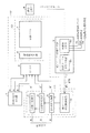
1.全体構成
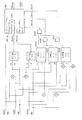
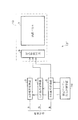
図2は、本実施形態に係るγ補正装置11を備えた液晶表示装置12、およびγ補正装置11の補正テーブルを設定するための周辺装置を示すブロック図である。液晶表示装置12は、γ補正装置11、ディスプレイ要素13、およびセレクタ(入力信号セレクタ)2を備えている。上記γ補正装置11は、R非線形変換器3、G非線形変換器4、B非線形変換器5(RGB非線形変換器3〜5)および補正テーブル設定制御装置10を備えている。上記ディスプレイ要素13には液晶駆動回路6および液晶パネル7が含まれる。上記周辺装置としては、信号発生器1(RGBW信号発生器)、輝度・色度計8、補正テーブル係数生成器9が含まれる。
【0060】
γ補正装置11の補正テーブルの設定は、液晶表示装置12の工場出荷時等において行われる。このとき、補正テーブルは補正テーブル設定制御装置10に設定される。補正テーブルが設定された後、液晶表示装置12の工場出荷時には、液晶表示装置12から信号発生器1や補正テーブル係数生成器9が切り離される。
【0061】
ここで、液晶表示装置12に入力されるRGBの映像信号はそれぞれ8ビット(0〜255階調の256階調分)のデータであり、ディスプレイ要素13は256階調の表示が可能なものである。RGB非線形変換器3〜5は、入力される映像信号を液晶パネル7のγ特性に適した信号に変換(γ補正)するためのものであるが、RGB非線形変換器3〜5は0〜255階調のうち予め定めたサンプリングポイントである64階調分について液晶パネル7のγ特性に応じた変換を行うとともに、他の階調については上記64階調分の階調に基づいて補間等を行い変換後のデータとする。この点に関する詳細は、後に図14に基づいて説明する。
【0062】
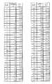
上記64階調分の階調iと上記256階調分の階調値I(i)とは、例えば図16のように対応付けられている。なお、以下において「階調」というときは上記64階調分の値を意味し、「階調値」というときは上記256階調分の値を意味する。
【0063】
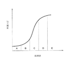
階調iと階調値I(i)との対応付けは、次のようにして定められる。階調値(液晶に印加される電圧に比例する)を入力した場合の液晶パネル7のγ補正を施す前のV−T特性(液晶パネル7における印加電圧(V)に対する透過率(T)の特性、透過率は輝度としてとらえることができる)は図15のようになっている。ここで、図15のAやEの領域では、階調値の変化に伴う出力輝度の変動が小さいため、階調iとして採用する階調値I(i)(サンプリングポイント)を多くとり、階調iを細かく設定することが望ましい。逆に、Cのように階調値の変化に伴う出力輝度の変動が大きい領域では、階調値I(i)(サンプリングポイント)は少なくてよい。このようにして、図16に示すように低階調領域や高階調領域でサンプリングポイントを多くとり、中階調領域でサンプリングポイントを少なくとった階調iが設定できる。なお、最低階調である0階調に対応する階調値I(0)は最低階調値である0に設定され、最高階調である63階調に対応する階調値I(63)は最高階調値である255に設定されるものとする。
【0064】
補正テーブルの設定を行うときには、まず、液晶パネル7の素特性を測定するために、信号発生器1において、RGB各最高階調、白(W)最高階調、およびWの他の階調(0〜62階調)の信号を出力する。ここで、「液晶パネル7の素特性」とは、補正前における液晶パネル7のV−T特性をいう。また、「R最高階調」とは、Rが最高階調であるとともにG,Bが最低階調であることをいう。同様に、「G最高階調」および「B最高階調」とは、それぞれGが最高階調であるとともにB,Rが最低階調であること、およびBが最高階調であるとともにR,Gが最低階調であることをいう。また、「W最高階調」とは、RGBすべてが最高階調であることをいう。
【0065】
次に、信号発生器1から出力させた信号がセレクタ2によって選択されて液晶駆動回路6に入力され、その信号に応じた表示が液晶パネル7にて行われる。輝度・色度計8は、上記液晶パネル7の表示を測定し、その結果を表すパネル素特性データを補正テーブル係数生成器9に送る。補正テーブル係数生成器9は、パネル素特性データと、外部から入力される目標輝度特性データYo、目標色度xo,yo、および低階調部処理用閾値THとから補正テーブル係数を生成し、その補正テーブル係数を補正テーブル設定制御装置10に送る。
【0066】
図16は、目標輝度特性データYoの例を表す図表である。目標輝度特性データYoは、各階調における輝度の目標値(目標輝度)を定めるデータである。図16は、γ=2.2の場合における階調i、各階調に対応する階調値I(i)、および各階調の目標輝度Yo(i)(63階調の輝度を100%としたときの相対値)との関係を示している。このように、目標輝度Yo(i)は、目標とするγ曲線のi階調における値を示すものである。なお、図16の階調iと階調値I(i)との関係は例えば補正テーブル設定制御装置10に設定されており、補正テーブル係数生成器9においても参照可能となっている。
【0067】
目標色度xo,yoは、ホワイトバランスを調整するための値である。目標色度xo,yoは、後述する低階調部を除いたWの全階調においてホワイトバランスが適正に調整された状態でのYxy表色系におけるそれぞれxおよびyの値である。
【0068】
また、低階調部処理用閾値THは、どの階調までを低階調部とするかを設定するための閾値である。
【0069】
補正テーブル設定制御装置10は、補正テーブル係数を記憶し、実際の映像表示の際に記憶した補正テーブル係数をRGB非線形変換器3〜5に送る。RGB非線形変換器3〜5は、実際の映像表示の際に入力されるRGBの映像信号に対して、補正テーブル係数に基づいて非線形変換を施し、変換後の映像信号をセレクタ2に送る。実際の映像表示の際には、セレクタ2がRGB非線形変換器3〜5からの映像信号を選択し、液晶駆動回路6に送る。これにより、液晶パネル7において変換後の映像信号に基づいた映像が表示される。
【0070】
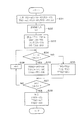
2.補正テーブル係数生成器における処理の流れ
図3は、上記補正テーブル係数生成器9における処理の流れを示すフローチャートである。まず、輝度・色度計8からのパネル素特性データとして、RGB各最高階調、およびWの0〜63階調をそれぞれ表示したときの輝度・色度計8での測定値のデータが入力される(ステップS20)。このデータは、輝度および色度からからなるYxy表色系のデータである。ここで、Yxy表色系とは、CIE(国際照明委員会)が提案した表色系であり、Yは輝度、x,yは色度を表している。また、Yxy表色系と後述するXYZ表色系とは、X:Y:Z=x:y:1−x−y、Y=Yの関係にある。本実施形態では、輝度・色度計8での測定値のデータとしてYxy表色系のデータが得られる場合について説明する。ただし、本発明は、パネル素特性データがYxy表色系のデータである場合に限らず、XYZ表色系等他の表色系のデータであってもよい。
【0071】
次に、ステップS20で入力されたデータに基づいて、Yxy表色系のデータをRGB表色系のデータに変換するための変換マトリクスであって、液晶パネル7のパネル特性に合った変換マトリクスを生成する(ステップS21)。
【0072】
次に、ステップS21で生成された変換マトリクスと、上記予め設定された目標色度xo,yoとに基づいて、色度を調整するためのRGBの目標混合比を生成する(ステップS22)。
【0073】
次に、ステップS21で生成された変換マトリクスを用いて、ステップS20で入力されたYxy表色系のデータをRGB表色系のデータに変換する(ステップS23)。
【0074】
次に、ステップS22で生成された目標混合比と、ステップS23で変換されたデータと、上記予め設定された目標輝度特性データYoとに基づいて、RGB各色の各階調における目標値を設定する(ステップS24)。
【0075】
次に、ステップS23で変換されたデータと、ステップS24で設定された目標値と、上記予め設定された低階調部処理用閾値THとに基づいて、低階調部の目標値を修正する(ステップS25)。
【0076】
そして、ステップS21〜S24で設定した目標値とパネルの素特性に基づいて補正テーブル係数を生成し(ステップS26)、補正テーブル係数を出力する(ステップS27)。
【0077】
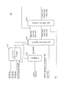
3.目標値設定部
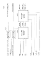
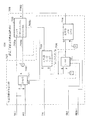
補正テーブル係数生成器9において、ステップS21〜S25の処理を行う部分を目標値設定部9a、ステップS26の処理を行う部分を補正テーブル係数生成部(補正値設定器)9bと称する(図1参照)。図1、図4〜図11に基づいて目標値設定部9aの構成について説明する。
【0078】
図1は、目標値設定部9aの構成を示すブロック図である。目標値設定部9aは、変換マトリクス生成器101(Yxy→RGB変換マトリクス生成器)、色度調整器102、RGB補正目標値設定器103、および低階調部目標値修正器104を含んで構成されている。図4〜図6、図11は、それぞれ変換マトリクス生成器101、色度調整器102、RGB補正目標値設定器103および低階調部目標値修正器104の構成を示すブロック図である。
【0079】
変換マトリクス生成器101には、各最高階調表示時のパネル素特性データが入力される。ここで、信号発生器1により液晶パネル7にてR最高階調を表示させたときに、輝度・色度計8にて測定される輝度をRY、色度をRx,Ry、同様にG最高階調を表示させたときの輝度をGY、色度をGx,Gy、B最高階調を表示させたときの輝度をBY、色度をBx,By、W最高階調を表示させたときの輝度をWY(63)、色度をWx(63),Wy(63)と表す。
【0080】
また、色度調整器102には、目標色度xo,yoが入力される。RGB補正目標値設定器103には、Wの各階調表示時のパネル素特性データ、および目標輝度Yo(0〜63)が入力される。ここで、信号発生器1により液晶パネル7にてWのi階調(iは0〜63の任意の整数)を表示させたときに、輝度・色度計8にて測定される輝度をWY(i)、色度をWx(i),Wy(i)と表す。なお、WY(0〜i)は、WY(0),WY(1),…,WY(i)を意味する(Wx,Wyについても同様)。
【0081】
また、低階調部目標値修正器104には、低階調部処理用閾値THが入力される。
【0082】
変換マトリクス生成器101は、図3のステップS21において変換マトリクスを生成する。変換マトリクス生成器101において生成された変換マトリクスは、色度調整器102およびRGB補正目標値設定器103に入力される。色度調整器102は、ステップS22において、目標色度xo,yoおよび変換マトリクスから色度を調整するためのRGBの目標混合比RH,GH,BHを生成する。RGB補正目標値設定器103は、ステップS23において、変換マトリクスを用いてWの0から63階調までのパネル素特性データをYxy表色系からRGB表色系に変換し、変換結果としてのR(0〜63),G(0〜63),B(0〜63)を出力する。また、RGB補正目標値設定器103は、ステップS24において、目標混合比RH,GH,BH、および目標輝度Yo(0〜63)からRGB各色の各階調における目標値TR(0〜63),TG(0〜63),TB(0〜63)、つまりRGB各色の目標値曲線を出力する。低階調部目標値修正器104は、ステップS25において、RGB補正目標値設定器103にて設定した目標値のうち、低階調部の目標値を修正した目標値TTR(0〜63),TTG(0〜63),TTB(0〜63)を出力する。
以下、図1の各部についてさらに詳細に説明する。
【0083】
3−1.変換マトリクス生成器
図4の変換マトリクス生成器101は、行列要素生成手段201〜204、行列要素修正手段205、逆行列計算手段206を含んで構成されている。なお、行列要素生成手段201〜204により行列計算装置が構成される。
【0084】
行列要素生成手段201〜204には、RGBおよびWの各最高階調を表示したときの輝度・色度計8からの測定値データがそれぞれ入力される。行列要素生成手段201〜204では、入力されるYxy表色系の測定値データをXYZ表色系のデータに変換する。この変換は、Yxy表色系のY,x,yとXYZ表色系のX,Y,Zとの間に、X:Y:Z=x:y:(1−x−y)、Y=Yの関係が成り立つことに基づく。
【0085】
各行列要素生成手段201〜204には加算器、乗算器、除算器等が設けられており、次の演算を行ってRX,RZ,GX,GZ,BX,BZ,WX,WZを求める。
RX=RY×Rx/Ry
RZ=RY×(1−Ry−Rx)/Ry
GX=GY×Gx/Gy
GZ=GY×(1−Gy−Gx)/Gy
BX=BY×Bx/By
BZ=BY×(1−By−Bx)/By
WX=WY(63)×Wx(63)/Wy(63)
WZ=WY(63)×(1−Wy(63)−Wx(63))/Wy(63)
なお、Yxy表色系の輝度RY,GY,BYとXYZ表色系の輝度RY,GY,BYとは同一である。また、RX,RY,RZと、GX,GY,GZと、BX,BY,BZと、WX,WY(63),WZとは、それぞれRGBおよびWの各最高階調を表示したときのXYZ表色系での三刺激値である。
【0086】
ここで、RGB表色系のR,G,Bと、XYZ表色系のX,Y,Zとは、一般に、上記RX,RY,RZ、GX,GY,GZ、BX,BY,BZを用いて式1のように表すことができる。なぜなら、R=1,G=B=0のときX=RX,Y=RY,Z=RZを満たし、G=1,B=R=0のときX=GX,Y=GY,Z=GZを満たし、B=1,R=G=0のときX=BX,Y=BY,Z=BZを満たすからである。なお、この式1におけるR,G,B,X,Y,Zは、各表色系における任意の値(1で規格化)である。
【0087】
【数1】

しかし、実際には、個々の液晶パネル7の特性にばらつきがあることから、式1では正しい変換が行えない場合がある。また、輝度・色度計8の誤差等によっても式1では正しい変換が行えない場合がある。そこで、これらの影響を考慮した変換マトリクスを得るために、行列要素を修正する係数k,l,mを用いて式2を作成する。式2の係数k,l,mを算出することにより、液晶パネル7の特性のばらつきや輝度・色度計8の誤差等の影響を考慮した変換マトリクスを得ることができる。
【0089】
【数2】
なお、式2において列ごとに係数を設定したのは次の理由による。例えば、第1列のRX,RY,RZは、R最高階調を測定したときに得た3刺激値であり、これらのデータは1度の測定で同時に得たものであることから、RX,RY,RZの比率は液晶パネル7の特性として信頼度が高い情報であると考えられる。一方、例えば第1行のRX,GX,BXは、RGB各最高階調を測定したときに得た3刺激値のX成分であり、これらは別々の測定によって得られたものである。そのため、係数を設定して修正すべきは、より信頼度が低いRX,GX,BXの比率と考えるのが妥当である。そこで、式2において列ごとに係数を設定するようにした。
【0091】
そこで、Wの各最高階調を表示したときに測定されるパネル素特性データを式2に代入することにより式3を作成する。この式3を解くことにより、係数k,l,mを算出し、式4に示す行列を得ることができる。なお、R1=RX/k、G1=GX/l、B1=BX/m、R2=RY/k、G2=GY/l、B2=BY/m、R3=RZ/k、G3=GZ/l、B3=BZ/mである。
【0092】
【数3】
【数4】
ここで、係数k,l,mが必ずしも1とはならない原因には、次のようなものが考えられる。例えば、R最高階調を表示する場合と、W最高階調を表示する場合とでは、Rに関しては同じ階調値が液晶駆動回路6に対して入力されることになるが、実際に液晶パネル7の液晶に印加される電圧はそれぞれの場合によって微妙に変化することがある。この変化の度合いが液晶パネル7ごとに異なるといった原因が考えられる。また、時間の経過に伴う液晶パネル7におけるバックライトの微妙な明るさの変化や温度による変化も原因として考えられる。
【0095】
なお、W最高階調を表示したときに得られる測定値データが最も正しいという保証はないが、補正テーブル係数生成器9では、後述するようにWの各階調(0〜63階調)の測定値データに基づいてRGB各色の各階調における目標値を設定するため、式3により係数k,l,mを求めるようにしている。
【0096】
このように、上記RX,RY,RZ、GX,GY,GZ、BX,BY,BZから式4の行列を得る演算を行列要素修正手段205により行う。つまり、行列要素修正手段205は、Wの最高階調の測定値が正しく変換されるように行列を修正するものである。
【0097】
さらに、式4の行列を逆行列計算手段206にて逆変換することにより、式5に示す行列を得る。これにより得られた行列が変換マトリクス生成器101にて生成すべき変換マトリクス(変換行列)となる。
【0098】
【数5】
3−2.色度調整器
図5の色度調整器102は、3つの色度調整手段301〜303を含んで構成されている。
【0100】
色度調整手段301〜303には、変換マトリクス生成器101で生成された行列(式5)の要素が入力される。具体的には、色度調整手段301にX1,Y1,Z1が、色度調整手段302にX2,Y2,Z2が、色度調整手段303にX3,Y3,Z3がそれぞれ入力される。また、色度調整手段301〜303には、目標色度xo,yoも入力される。
【0101】
ここで、Tx=xo、Ty=yo、Tz=1−Tx−Tyとしたとき、色度調整手段301〜303は次の演算を行ってそれぞれRH,GH,BHを算出する。
RH=X1×Tx+Y1×Ty+Z1×Tz
GH=X2×Tx+Y2×Ty+Z2×Tz
BH=X3×Tx+Y3×Ty+Z3×Tz
この演算は、式5の行列と(Tx,Ty,Tz)との積、つまり(Tx,Ty,Tz)を式5の行列により変換する演算である。これにより得られるRH,GH,BHは、適正なホワイトバランスを得るためのRGBの混合比を表すことになる。
【0102】
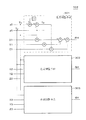
3−3.RGB補正目標値設定器
図6のRGB補正目標値設定器103は、変換手段401(Yxy→RGB変換手段)、RGB目標値(最高階調)設定器402、およびRGB目標値(64階調)設定器403を含んで構成されている。
【0103】
変換手段401には、Wの各階調(0〜63階調)を表示したときの輝度・色度計8からの測定値データが入力される。
【0104】
変換手段401では、変換マトリクス生成器101で生成された変換マトリクス(式5)を用いて、入力されるWの各階調におけるYxy表色系のデータWY(0〜63),Wx(0〜63),Wy(0〜63)を、各階調ごとにRGB表色系のデータR(0〜63),G(0〜63),B(0〜63)に変換して出力する。
【0105】
この変換は、式6に基づく。なお、WX(i)=WY(i)×Wx(i)/Wy(i)、WZ(i)=WY(i)×(1−Wy(i)−Wx(i))/Wy(i)である。
【0106】
【数6】
ここで、式6は、液晶パネル7における特性のばらつき等の影響を考慮した変換マトリクス(式5)を用いた変換式である。これにより、変換の際のオーバーフローや変換誤差等を抑制することができる。式6において式5の変換マトリクスを用いずに個々の液晶パネル7において共通に設定された変換マトリクス(既存の変換マトリクス)を用いたのでは、変換の際のオーバーフローや変換誤差等が生じ得る。例えば、W最高階調に対応するWX(63),WY(63),WZ(63)を上記既存の変換マトリクスを用いて変換したのでは、液晶パネル7個々の特性のばらつきによって変換結果が(255,255,255)に相当する値にならず、(255,252,253)や(254,256,258)のように本来の最高階調値から外れた値になる可能性がある。特に後者の場合では、8ビットのデータ制度では扱えない値となり、データのオーバーフローが起こる。
【0108】
また、図6に示すように、RGB目標値(最高階調)設定器402には、変換手段401の変換結果であって、Wの最高階調を表示したときのデータに対応するR(63),G(63),B(63)と、色度調整器102で得られたRGBの混合比を表すデータRH,GH,BHとが入力される。
【0109】
RGB目標値(最高階調)設定器402では、RH:GH:BHの比率を満たすという条件のもとに、液晶パネル7において最も高い輝度を表示できるようなRGBの各値の組み合わせを決定して出力する。このRGBの各値(最高階調目標値)をそれぞれ、TRmax,TGmax,TBmaxとする。
【0110】
RGB目標値(最高階調)設定器402では、R(63),G(63),B(63)の何れを基準にするかを決めるとともに、その基準になる値を最高階調目標値とし、その最高階調目標値とRH:GH:BHの比率とに基づいて他の2色の最高階調目標値を計算する。
【0111】
R(63),G(63),B(63)の何れを基準にするかを決める方法について説明する。仮にR(63)を基準にする場合を想定してみる。このとき、RGB各色の最高階調目標値はそれぞれ、R(63),R(63)×GH/RH,R(63)×BH/RHとなる。ここで、(R(63)×GH/RH)>G(63)、または(R(63)×BH/RH)>B(63)となると、GまたはBの最高階調目標値が液晶パネル7で表示可能な値を超えることになり、実際に液晶パネル7において表示不可能となる。つまり、R(63)を基準にするとBまたはGの最高階調を表示できないことになる。同様に、G(63),B(63)を基準にする場合を想定して、それぞれの場合において最高階調目標値が液晶パネル7に表示可能な値であるかどうかを判定する。
【0112】
少なくともR(63),G(63),B(63)のうち何れか1つを基準にした場合に得られる最高階調目標値は、液晶パネル7で表示可能な値となるはずであるので、その場合の各色の最高階調目標値を実際の最高階調目標値として決定する。
【0113】
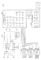
RGB目標値(最高階調)設定器402の内部構成を図7に示す。なお、図7および図7に基づく以下の説明は、Rの構成に関するものである。Rの構成と同様であるGの構成およびBの構成に関しては図示および説明を省略する(後述する図8、図11〜図14およびそれらの説明についても同様)。
【0114】
図7の構成には、乗算器、除算器、比較器、AND回路、およびセレクタ501が含まれる。セレクタ501は、被選択入力501a・501b・501c、および選択入力501d・501e・501fを有している。
【0115】
被選択入力501a・501b・501cには、それぞれRを基準としたときに最高階調目標値となるべきR(63)、Gを基準としたときに最高階調目標値となるべきG(63)×RH/GH、Bを基準としたときに最高階調目標値となるべきB(63)×RH/BHが入力される。
【0116】
選択入力501d・501e・501fには、それぞれ次の条件1から3を満たす場合に「1」、満たさない場合に「0」が入力される。条件1は、R(63)×GH/RH≦G(63)、かつ、R(63)×BH/RH<B(63)であり、条件2は、G(63)×BH/GH≦B(63)、かつ、G(63)×RH/GH<R(63)であり、条件3は、B(63)×RH/BH≦R(63)、かつ、B(63)×GH/BH<G(63)である。
【0117】
そして、セレクタ501は、選択入力501dが「1」である場合に被選択入力501aのR(63)をTRmaxとして出力し、選択入力501eが「1」である場合に被選択入力501bのG(63)×RH/GHをTRmaxとして出力し、選択入力501fが「1」である場合に被選択入力501cのB(63)×RH/BHをTRmaxとして出力する。
【0118】
なお、比較器502は、RH×G(63)≧GH×R(63)の場合にAND回路505に「1」を、AND回路506に「0」を出力し、GH×R(63)>RH×G(63)の場合にAND回路505に「0」を、AND回路506に「1」を出力する。比較器503は、RH×B(63)>BH×R(63)の場合にAND回路505に「1」を、AND回路507に「0」を出力し、BH×R(63)≧RH×B(63)の場合にAND回路505に「0」を、AND回路507に「1」を出力する。比較器504は、GH×B(63)≧BH×G(63)の場合にAND回路506に「1」を、AND回路507に「0」を出力し、BH×G(63)>GH×B(63)の場合にAND回路506に「0」を、AND回路507に「1」を出力する。
【0119】
AND回路505は、比較器502の出力と比較器503の出力との論理積を選択入力501dに入力する。AND回路506は、比較器502の出力と比較器504の出力との論理積を選択入力501eに入力する。AND回路507は、比較器503の出力と比較器504の出力との論理積を選択入力501fに入力する。
【0120】
また、図6に示すように、RGB目標値(64階調)設定器403には、RGB目標値(最高階調)設定器402から出力されるTRmax,TGmax,TBmaxと、Wの各階調における目標輝度Yo(0〜63)(図16参照)と、クロック信号CLKと、リセット信号RESETとが入力される。
【0121】
RGB目標値(64階調)設定器403では、RGBそれぞれに設定された最高階調目標値TRmax,TGmax,TBmaxと、各階調での目標輝度Yo(i)とに基づいて、各階調での目標値(各階調目標値)を決定して出力する。このRGBの各階調での目標値をそれぞれ、TR(0〜63),TG(0〜63),TB(0〜63)とする。なお、クロック信号CLKおよびリセット信号RESETは外部から供給されるものである。
【0122】
RGB目標値(64階調)設定器403の内部構成を図8に示す。図8の構成には、乗算器、除算器、セレクタ601、およびクロックカウンタ602が含まれる。セレクタ601は、被選択入力601a・601b、および選択入力601cを有している。
【0123】
被選択入力601a・601bには、それぞれTRmaxおよびTRmax×Yo(i)/Yo(63)が入力される。なお、目標輝度Yo(i)は、クロック信号CLKのクロックパルスに基づいて0階調の目標輝度Yo(0)から63階調の目標輝度Yo(63)まで順次変化する。
【0124】
選択入力601cには、クロックカウンタ602によるクロック信号CLKのクロックパルスのカウント値iが入力される。なお、クロックカウンタ602のカウント値は、i=63までカウントされるとi=0にリセットされる。
【0125】
なお、セレクタ601の選択入力601cに対してカウント値i=i1が入力されているときには、被選択入力601bにTRmax×Yo(i1)/Yo(63)が入力されるようにタイミングが調整されている。
【0126】
セレクタ601では、選択入力601cに入力されるカウント値iが63未満の場合には被選択入力601bの値、つまりTRmax×Yo(i)/Yo(63)を出力し、選択入力601cに入力されるカウント値iが63の場合には被選択入力601aの値、つまりTRmaxを出力する。これにより、セレクタ601は、最高階調においてはTRmaxをTR(63)として出力し、最高階調以外の階調においてはTRmax×Yo(i)/Yo(63)をTR(i)として出力する。これにより、すべての階調における目標値TR(0〜63)が得られる。
【0127】
ここで、i階調の目標値TR(i)と最高階調の目標値TR(63)との比率と、i階調の目標輝度Yo(i)と最高階調の目標輝度Yo(63)との比率が等しくなる。したがって、目標値TR(0〜63)で表される曲線は、最高階調がTRmaxであり、目標輝度Yo(0〜63)で表される曲線と同じ傾向を有する曲線になる。つまり、目標値TR(0〜63)は、最高階調がRGB目標値(最高階調)設定器402にて設定されたTRmaxであり、各階調が目標輝度Yoの傾向を反映したものとなる。
【0128】
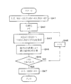
3−4.低階調部目標値修正器
図9は、図1の低階調部目標値修正器104における処理の流れを示すフローチャートである。低階調部目標値修正器104では、図10(a)に示すように、RGB補正目標値設定器103で設定したTR(0〜63),TG(0〜63),TB(0〜63)で表される曲線(目標値曲線)が、低階調部において液晶パネル7に表示不可能な値を要求している場合に、図10(b)に示すように目標値を表示可能な値にするとともに、階調が上がるにつれて低階調部の修正した目標値から中〜高階調部の修正しない目標値への移行が滑らかになるように目標値の修正を行う。なお、低階調部から中〜高階調部への移行を考慮せずに目標値を修正すると、図10(c)に示すように低階調部の修正した目標値から中〜高階調部の修正しない目標値への移行の変化が顕著にあらわれ、低階調部と中〜高階調部との間で階調変化が不規則になり表示品位が低下してしまうことがある。
【0129】
図10(a)〜図10(c)は、図2のディスプレイ要素13へ入力される階調と、ディスプレイ要素13の液晶パネル7において入力された階調に基づく表示を行った場合の輝度(出力輝度)との関係を表すグラフである。なお、図10(a)〜図10(c)では横軸(階調)および縦軸(出力輝度)を対数目盛で表している。また、図10(a)〜図10(c)におけるYminは、液晶パネル7にて表示できる最低の出力輝度を示している。ディスプレイ要素13に対しては実際には8ビットデータである階調値I(図16参照)が入力されるが、ここでは説明の便宜上各グラフの横軸を階調iとしている。図10(a)〜図10(c)は、RGBおよびWそれぞれに当てはまる傾向を示したものである。
【0130】
低階調部目標値修正器104には、RGB補正目標値設定器103の変換手段401による変換結果であるR(0〜63),G(0〜63),B(0〜63)と、RGB補正目標値設定器103のRGB目標値(64階調)設定器403で設定されたTR(0〜63),TG(0〜63),TB(0〜63)と、低階調部処理用閾値THとが入力される(ステップS31)。
【0131】
そして、階調iを初期値0に設定し(ステップS32)、修正パラメータDR,DG,DBをそれぞれ求める(ステップS33)。この修正パラメータDR,DG,DBは、RGB目標値(64階調)設定器403において設定した目標値曲線(図10(a)参照)のうち、最低階調における目標値TR(0),TG(0),TB(0)から、最低階調におけるパネル素特性の値R(0),G(0),B(0)(図10(a)におけるYminに相当)を引いた値である。なお、R(0),G(0),B(0)はRGB補正目標値設定器103から出力される。
【0132】
そして、階調iが低階調部処理用閾値THより小さい場合には(ステップS34)、RGB目標値(64階調)設定器403にて設定した目標値TR(i),TG(i),TB(i)から、それぞれ修正パラメータDR,DG,DBを引くことで、修正目標値TTR(i),TTG(i),TTB(i)を設定する(ステップS35)。階調iが低階調部処理用閾値TH以上である場合には(ステップS34)、RGB目標値(64階調)設定器403にて設定した目標値TR(i),TG(i),TB(i)をそのまま非修正目標値TTR(i),TTG(i),TTB(i)として設定する(ステップS36)。この処理を0階調から63階調まで繰り返す(ステップS34〜S38)。そして、得られた修正または非修正目標値TTR(0〜63),TTG(0〜63),TTB(0〜63)を出力する(ステップS39)。
【0133】
ここで、0階調ではパネル素特性がそのまま修正目標値となり、液晶パネル7に表示可能な値が修正目標値として設定されることになる。また、修正パラメータは常に一定の値であり、ステップS35では目標値から一定の値である修正パラメータを引いて修正目標値を設定することになる。ここで、目標値曲線は図16に示したγカーブを表す目標輝度特性データYoに基づいて設定されたものであり、目標値曲線もγカーブ(べき乗カーブ)となる。したがって、目標値は階調が上がるにつれてべき乗的に大きくなるため、修正パラメータの絶対的な値は一定でも、目標値からみた相対的な大きさ、つまり目標値に対する修正パラメータの割合は、階調が大きくなるにつれて徐々に小さくなる。そこで、目標値に対する修正パラメータによる影響が無視できる程度に小さくなるまでの階調を低階調部とみなし、その低階調部において目標値を修正することで、目標値を修正した低階調部から、目標値を修正しない中〜高階調部への移行を滑らかにすることができる。
【0134】
なお、低階調部処理用閾値THを具体的にどの階調に設定するかは、実際の表示を確認して設定すればよいが、例えば目標値が修正パラメータの値の10倍(望ましくは100倍)以上となる階調を低階調部処理用閾値THに設定することが好適である。
【0135】
低階調部目標値修正器104の内部構成を図11に示す。図11の構成には、減算器701、加算器702、比較器703・704、セレクタ705およびクロックカウンタ706が含まれる。セレクタ705は、被選択入力705a・705b、および選択入力705cを有している。
【0136】
なお、減算器701、加算器702、比較器703・704およびクロックカウンタ706により修正目標値設定手段707が構成され、セレクタ705により修正/非修正目標値選択手段708が構成される。また、減算器701により修正パラメータ設定器が構成される。
【0137】
被選択入力705a・705bには、それぞれTR(i)およびTR(i)−(TR(0)―R(0))が入力される。なお、TR(i)およびR(i)は、クロック信号CLKのクロックパルスに基づいて0階調のTR(0)およびR(0)から63階調のTR(63)およびR(63)まで順次変化する。
【0138】
選択入力705cには、クロックカウンタ706によるクロック信号CLKのクロックパルスのカウント値iが低階調部処理用閾値THより小さい場合には1が入力され、カウント値iが低階調部処理用閾値TH以上の場合には0が入力される。なお、クロックカウンタ706のカウント値は、i=63までカウントされるとi=0にリセットされる。
【0139】
なお、セレクタ705の選択入力705cに対してカウント値i=i1に基づく値(1または0)が入力されているときには、被選択入力705aにTR(i1)が入力され、被選択入力705bにTR(i1)−(TR(0)―R(0))が入力されるようにタイミングが調整されている。
【0140】
セレクタ705では、選択入力705cに1が入力されている場合、つまり低階調部処理用閾値THより小さい階調iのTR(i)およびTR(i)−(TR(0)―R(0))がそれぞれ被選択入力705aおよび被選択入力705bに入力されている場合には、被選択入力705bの値、つまりTR(i)−(TR(0)―R(0))を出力し、選択入力705cに0が入力されている場合、つまり低階調部処理用閾値TH以上の階調iのTR(i)およびTR(i)−(TR(0)―R(0))がそれぞれ被選択入力705aおよび被選択入力705bに入力されている場合には、被選択入力705aの値、つまりTR(i)を出力する。これにより、セレクタ705は、低階調部処理用閾値THより小さい階調iにおいては修正目標値TTR(i)を、低階調部処理用閾値TH以上の階調iにおいては非修正目標値TTR(i)を出力する。
【0141】
なお、比較器703は、低階調部処理用閾値THとクロックカウンタ706によるカウント値iを比較し、カウント値iが低階調部処理用閾値THより小さい場合にはセレクタ705の選択入力705cに1を入力し、カウント値iが低階調部処理用閾値TH以上の場合にはセレクタ705の選択入力705cに0を入力する。また、比較器704は、クロックカウンタ706のカウント値iが0のときのみ1を出力し、他では0を出力する。減算器701はイネーブル端子を有し、そのイネーブル端子には比較器704の出力が入力される。減算器701は、比較器704の出力が1の場合、つまりTR(0)およびR(0)が減算器701に入力されている場合にTR(0)−R(0)の演算を行ってその結果を出力し、比較器704の出力が0の場合には、直前における比較器704の出力が1の場合の出力を維持する。このように、減算器701は修正パラメータを算出する処理(図9におけるステップS33)を行う。
【0142】
本実施形態では、低階調部目標値修正器104は、上述したRGB補正目標値設定器103にて設定されたTR(0〜63),TG(0〜63),TB(0〜63)で表される目標値曲線を修正するものとして説明している。しかし、低階調部目標値修正器104は、本実施形態の補正テーブル係数生成器9以外の装置において、他の方法で設定された目標値曲線を修正するために用いることもできる。このとき、対象となる映像信号はカラーに限らず、モノクロであってもよい。
【0143】
4.補正テーブル係数生成部
以上により設定された修正目標値および非修正目標値に基づいて、補正テーブル係数生成部9bにより補正テーブル係数を生成する処理は図12のようになる。この処理では、階調iにおいて修正または非修正目標値TTR(i)を表示させるために、液晶駆動回路6に入力すべき階調値である補正値(補正入力値)HR(i)を算出し、階調iと補正値HR(i)との対比表(補正テーブル)を得る。補正値HR(i)が階調iに対応する補正テーブル係数である。
【0144】
図12は、補正テーブル係数生成部9bにおける処理の流れを示すフローチャートである。また、図13は、図12の処理の内容を説明するためのグラフである。
【0145】
補正テーブル係数生成部9bには、RGB補正目標値設定器103の変換手段401による変換結果であるR(0〜63)と、低階調部目標値修正器104から出力されるTTR(0〜63)と、各階調iに対応する階調値IR(i)(図16参照)が入力される(ステップS41)。
【0146】
そして、階調iを初期値0に設定し(ステップS42)、R(0〜63)およびTTR(0〜63)に基づき、
R(j)≦TTR(i)、かつ、TTR(i)≦R(j+1)
を満たすjを検索する(ステップS43)。そして、式7に基づき、得られたjに対応するR(j)、R(j+1)、IR(j)、IR(j+1)を用いてR(j)とR(j+1)との間を線形1次補間することにより補正値HR(j)を算出する(ステップS44)。
【0147】
【数7】
この処理を0階調から63階調まで繰り返す(ステップS43〜S46)。そして、得られた補正値HR(0〜63)を補正テーブル設定制御装置10(図2参照)に対して出力する(ステップS47)。なお、図12の処理は周知の線形補間の処理であるため、この処理を行う回路構成については説明を省略する。
【0149】
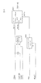
5.補正テーブル設定制御装置、RGB非線形変換器
図14は、補正テーブル設定制御装置10およびR非線形変換器3の構成を示すブロック図である。補正テーブル係数生成部9bから出力された補正値HR(0〜63)は、補正テーブル設定制御装置10のメモリ10aに記憶される。また、メモリ10aに記憶された各階調iに対応する補正値HR(i)は、各階調(i)に対応して設けられたレジスタ10b…にそれぞれ設定される。これにより、補正テーブルの設定が完了する。
【0150】
実際に映像信号が入力された場合には、R非線形変換器3により上記設定された補正テーブルを用いて次のような変換が行われる。ここで、R非線形変換器3には、セレクタ3a、重み計算部3b、乗算器、および加算器が含まれる。
【0151】
セレクタ3aは、R非線形変換器3に入力された映像信号が示す階調値を挟む互いに隣り合う階調値IR(j)およびIR(j+1)を検索し、その検索結果に基づいてHR(j)およびHR(j+1)を選択してそれぞれ出力する。例えば、階調値IRが図16のように設定されており、映像信号が示す階調値が97である場合、j=30となるためHR(30)およびHR(31)を選択し、それぞれ第1および第2出力から出力する。
【0152】
重み計算部3bは、R非線形変換器3に入力された映像信号に基づいてセレクタ3aの第1および第2出力の出力値を線形補間するための第1および第2重み係数を算出する。上記の例では、第1および第2出力の出力値に乗じるための第1および第2重み係数がそれぞれ式8および式9により求められる。
1−(97−96)/(100−96)=0.75 … (8)
1−(100−97)/(100−96)=0.25 … (9)
そして、第1および第2出力の出力値に第1および第2重み係数をそれぞれ乗算器により乗じ、乗算結果を加算器により加算する。この計算結果がセレクタ2(図2参照)への出力となる。上記の例では、この計算が式10のようになる。
HR(30)×0.75+HR(31)×0.25 … (10)
以上の方法により、パネルの素特性から目標曲線を設定し、それに基づいて補正テーブルを生成し、パネルにγ補正を施す。
【0153】
6.まとめ
以上のように、本実施形態に係る液晶表示装置12は、セレクタ2、γ補正装置11(RGB非線形変換器3〜5、補正テーブル設定制御装置10)、およびディスプレイ要素13(液晶駆動回路6、液晶パネル7)を備えている。また、γ補正装置11の補正テーブルを設定するための周辺装置には、信号発生器1、輝度・色度計8、および補正テーブル係数生成器9が含まれる。各構成要素の構成、機能等をまとめると次のようになる。
【0154】
(1)本実施形態に係る補正テーブル係数生成器9(図1参照)は、目標値設定部9a(Yxy表色系からXYZ表色系を経てRGB表色系への変換マトリクスを生成する変換マトリクス生成器101、色度調整器102、RGB補正目標値設定器103、低階調部目標値修正器104)、および補正テーブル係数生成部9bを含んでいる。
【0155】
(2)変換マトリクス生成器101(図4参照)は、個々の液晶パネル7の表示特性の違いを考慮し、各液晶パネル7の特性にあった変換マトリクスを生成することを目的とし、行列要素生成手段201、行列要素修正手段205、および逆行列計算手段206を含み、これらによりYxy表色系からXYZ表色系を経てRGB表色系への変換マトリクスを生成する。
【0156】
(3)行列要素生成手段201(図4参照)は、(X:Y:Z)=(x:y:(1−x−y))の関係に基づいて、RGB各色の最高階調を液晶パネル7にて表示させた場合におけるYxy表色系の測定値(RY,Rx,Ry,GY,Gx,Gy,BY,Bx,By)をそれぞれXYZ表色系に変換した値(RX,RY,RZ,GX,GY,GZ,BX,BY,BZ)を、RGB表色系からXYZ表色系への変換マトリクス(式1参照)の行列要素(行列係数)として生成する。また、行列要素生成手段201は、W最高階調を液晶パネル7にて表示させた場合におけるYxy表色系の測定値(WY(63),Wx(63),Wy(63))をそれぞれXYZ表色系に変換した値(WX,WY,WZ)をも生成する。
【0157】
(4)行列要素修正手段205(図4参照)は、行列要素生成手段201が生成した行列要素からなる変換マトリクス(3行×3列の行列)に対して、第1列、第2列および第3列に属する行列要素にそれぞれ係数(k,l,m)をつけ、例えばRGB表色系の8ビットの映像信号であってW最高階調を表示するための値(1で規格化したもの)の上記係数をつけた変換マトリクスを用いた変換結果が、W最高階調を液晶パネル7にて表示させた場合におけるYxy表色系の測定値をXYZ表色系に変換した値(WX,WY,WZ)と等しくなるように行列式(式2)をつくり、連立方程式を解くことによって各列につけた係数を求め、行列要素を修正する。
【0158】
(5)色度調整器102(図5参照)は、液晶パネル7の表示の色度を目標値に調整することを目的とし、目標色度(xo,yo)と変換マトリクス生成器101で生成した変換マトリクスを用い、W最高階調におけるRGB目標混合比(RH,GH,BH)を求める色度調整手段301により、白表示におけるRGBの目標混合比を設定し、液晶パネル7の表示の色度を調整する。
【0159】
(6)RGB補正目標値設定器103(図6参照)は、Wの各階調を液晶パネル7にて表示させた場合におけるYxy表色系の測定値(WY(0〜63),Wx(0〜63),Wy(0〜63))を、変換マトリクス生成器101で生成した変換マトリクスによりRGB表色系に変換する変換手段401と、RGB目標値(最高階調)設定器402と、RGB目標値(64階調)設定器403とを含んで構成される。
【0160】
(7)RGB目標値(最高階調)設定器402(図7参照)は、色度調整器102にて求めたRGB目標混合比と、W最高階調を液晶パネル7にて表示させた場合におけるYxy表色系の測定値(RY,Rx,Ry,GY,Gx,Gy,BY,Bx,By)を、変換手段401によって変換したRGB表色系の値R(63),G(63),B(63)から、RGBそれぞれの色を基準とした場合に、他の色が液晶パネル7に表示可能かどうかを判定することで、RGB目標混合比を満たし、かつ、液晶パネル7に表示可能な最大のRGBの組み合わせを設定し、RGBの最高階調目標値(TRmax,TGmax,TBmax)とする。
【0161】
(8)RGB目標値(64階調)設定器403(図8参照)は、目標輝度Yo(0〜63)と、RGB目標値(最高階調)設定器402にて設定したRGBの最高階調目標値(TRmax,TGmax,TBmax)をもとに、最高階調(63階調)における目標輝度Yo(63)と各階調における目標輝度Yo(0〜62)との比と、RGBの最高階調目標値とRGBの各階調目標値(TR(0〜62),TG(0〜62),TB(0〜62))との比が同じになるように、RGBの各階調目標値を設定する。
【0162】
(9)低階調部目標値修正器104(図11参照)は、修正目標値設定手段707と、修正/非修正目標値選択手段708とを含んで構成される。
【0163】
(10)修正目標値設定手段707(図9,11参照)は、RGB各色ごとに、最低階調(0階調)における、目標値(TR(0),TG(0),TB(0))と、変換手段401によって変換したRGB表色系の値(R(0),G(0),B(0))との差を修正パラメータとし、修正パラメータを各階調目標値(TR(0〜63),TG(0〜63),TB(0〜63))から引くことで修正目標値(TTR(0〜63),TTG(0〜63),TTB(0〜63))を得る。
【0164】
(11)修正/非修正目標値選択手段708(図9,11参照)は、修正目標値設定手段707で設定した修正目標値(TTR(0〜63),TTG(0〜63),TTB(0〜63))と、RGB目標値(64階調)設定器403にて設定した各階調目標値(TR(0〜63),TG(0〜63),TB(0〜63))とを、階調が低階調部処理用閾値TH以上となる階調では各階調目標値を選び、階調が低階調部処理用閾値TH未満の階調では修正目標値を選択し、修正または非修正目標値(TTR(0〜63),TTG(0〜63),TTB(0〜63))として出力する。
【0165】
(12)補正テーブル係数生成部9b(図2,12参照)は、低階調部目標値修正器104で設定した修正または非修正目標値(TTR(0〜63),TTG(0〜63),TTB(0〜63))と、変換手段401によって変換したRGB表色系の値(R(0〜63),G(0〜63),B(0〜63))とに基づいて、映像信号が示す階調値に対する目標出力輝度と同じ輝度を出力する補正値HR(0〜63)を計算し、0〜63階調の補正値HR(0〜63)を補正テーブル係数として生成する。
【0166】
(13)液晶パネル7が表示可能な256階調分の階調値I(i)の中から、RGB補正目標値設定器103以降で処理する0〜63階調(図16参照)の選択方法は、液晶パネル7のV−T特性(図15参照)をもとに、階調値の変化に伴う出力輝度の変動が小さい領域(例えば図15のAやEの領域)では階調iとして採用する階調値I(i)(サンプリングポイント)を多くとり、階調値の変化に伴う出力輝度の変動が大きい領域(例えば図15のCの領域)では階調iとして採用する階調値I(i)(サンプリングポイント)を少なくとるようにする。
【0167】
このように、補正テーブル係数生成器9は、液晶パネル7にあったXYZ表色系からRGB表色系への変換マトリクスを生成することで、変換の際に生じるオーバーフローや変換誤差等のエラーを避け、以降の素特性データの変換を正確にすることができる。また、補正テーブル係数生成器9は、低階調部では液晶パネル7に表示不可能な目標値を修正し、低階調部の目標値から中〜高階調部の目標値への移行がスムーズになる目標値の修正手段としての低階調部目標値修正器104を備えている。
【0168】
補正テーブル係数生成器9は、液晶パネル7にあった変換マトリクスを生成するために、液晶パネル7の素特性を測定し、個々の液晶パネル7それぞれにおいてW最高階調の測定値が、例えば8ビットデータで必ず(255,255,255)に変換されるように変換マトリクスを修正する。
【0169】
また、補正テーブル係数生成器9は、色度を正確に調整するために、目標色度(xo,yo)を、上記修正した変換マトリクスでRGB表色系に変換し、RGBの目標混合比を求める。そして、得られた目標混合比にあわせてW最高階調におけるRGB目標値を計算する。そして、最高階調における目標値と各階調における目標値との比が、最高階調における目標輝度と各階調における目標輝度との比と同じになるように各階調の目標値を設定する。
【0170】
このとき、低階調部における目標値が液晶パネル7に表示不可能な値を要求している場合に、補正テーブル係数生成器9は、「最低階調における目標値と素特性の差」を修正パラメータとして目標値から引くことで、目標値を液晶パネル7に表示可能な値に修正する。
【0171】
目標値を修正した低階調部から修正しない中〜高階調部への目標値の移行がスムーズにならない場合、暗い映像を表示したときに目標値を修正した階調と修正しない階調の境界においてわずかな入力階調の違いで色味や輝度が大きく変化し、品質の悪い映像になってしまう。
【0172】
ここで、修正パラメータは一定値であるため、階調が大きくなるにつれて目標値が修正パラメータから受ける相対的な影響は小さくなる。つまり、低階調部から中〜高階調部へ移行する階調は、修正パラメータの影響が無視できるレベルとなる階調であれば、その境界での差は無視できることになる。このことに基づいて、目標値を修正した低階調部と、修正しない中〜高階調部への移行をスムーズに行う。つまり、最低階調から、修正パラメータが無視できるレベルに至るまでを低階調部として目標値を修正することで、低階調部から中〜高階調部へのスムーズな移行を実現することができる。これにより、低階調部と中〜高階調部の境界における目標値修正による影響が目立たなくすることができる。
【0173】
以上により、個々の液晶パネル7の特性に特化した品質の高いγ補正映像を液晶パネル7に表示させることができる。
【0174】
本発明に係る補正特性決定装置は、本実施形態の補正テーブル係数生成器9に相当している。この補正特性決定装置による補正特性の決定の対象は、液晶表示装置12に限らず、一般に三原色信号(RGB信号等)からなる映像信号に補正を施し、補正後の信号に基づいて表示手段にカラー映像を表示するものであればよい。表示手段としては、本実施形態の液晶パネル7以外に、CRT、プラズマディスプレイパネル、エレクトロルミネッセンスパネル等が考えられる。
【0175】
本発明に係る補正特性決定装置は、表示手段の表示における発光状態の測定結果を三刺激値に変換可能な値で示したデータである測定データ(パネル素特性データ)を、変換行列を用いて上記三原色の輝度データに変換するデータ変換手段(変換手段401)と、上記データ変換手段による変換結果に基づいて補正特性を決定する補正特性決定手段(RGB目標値(最高階調)設定器402、RGB目標値(64階調)設定器403、低階調部目標値修正器104)と、上記変換行列を生成する行列生成手段(変換マトリクス生成器101)とを備える。上記行列生成手段は、上記表示手段が各原色の最高階調を表示したときの測定データに基づいて上記変換行列の逆行列の行列要素を生成する行列要素生成手段(行列要素生成手段201〜204)と、上記表示手段が白の最高階調を表示したときの測定データに基づいて上記行列要素生成手段により生成された行列要素を修正する行列要素修正手段(行列要素修正手段205)と、上記修正された行列要素からなる行列の逆行列を生成する逆行列生成手段(逆行列計算手段206)とを備えている。
【0176】
なお、本実施形態では、補正特性決定手段に低階調部目標値修正器104を含めているが、低階調部における修正を必要としない場合には、低階調部目標値修正器104を含めなくてもよい。
【0177】
補正特性は、映像信号の階調値と、その階調値が表示装置に入力されたときに、表示手段における実際の出力輝度として適切な値(目標出力輝度)との関係として決定される。本実施形態では、映像信号の階調値I(i)に対応付けられた階調iと、目標値(目標出力輝度)TR(0〜63),TG(0〜63),TB(0〜63)との関係として決定されている。
【0178】
そして、行列生成手段が表示手段の特性にあった変換行列を生成することで、データ変換手段によるデータ変換を適正化することができる。その結果、データ変換の際のオーバーフローや変換誤差等を抑制することができ、補正特性決定手段による補正特性の決定をより正確にすることができるようになる。
【0179】
また、本発明に係る補正特性決定装置は、上記表示手段における表示の色度を設定するために目標となる色度を三刺激値に変換可能な値で示す目標色度データ(目標色度xo,yo)を、上記変換行列を用いて変換することで、三原色の出力輝度の混合比(目標混合比RH,GH,BH)を生成する目標混合比生成手段(色度調整器102)を備え、上記補正特性決定手段は、上記表示手段が白の最高階調を表示したときの測定データを上記データ変換手段にて変換した結果と、上記目標混合比とに基づいて、上記映像信号における各原色信号の最高階調値に対応する目標出力輝度を決定する最高階調決定手段(RGB目標値(最高階調)設定器402)を備えることが望ましい。
【0180】
このように、表示手段の特性にあった変換行列を用いて目標色度データを変換することで、三原色の輝度データが本来の値からずれることを抑制し、三原色の出力輝度の正確な混合比を生成することができる。この混合比を用いて最高階調決定手段が映像信号における各原色信号の最高階調値に対応する目標出力輝度を決定することで、最高階調を正確な混合比に設定することができる。
【0181】
上記最高階調決定手段は、上記表示手段が白の最高階調を表示したときの測定データを上記データ変換手段にて変換した結果における各原色の輝度データの比率と、上記目標混合比とに基づいて、輝度データが最も不足しているものをその原色信号の最高階調値に対応する目標出力輝度とし、この目標出力輝度を基準にして上記目標混合比に基づいて他の原色信号の最高階調値に対応する目標出力輝度を決定することが望ましい。
【0182】
上記の構成では、基準となる原色以外の原色の目標出力輝度が変換結果の輝度データ以下になる。したがって、何れの原色においても、表示手段にて実際に表示できない輝度を最高階調値に対応する目標出力輝度として決定してしまう、という不具合が発生しない。したがって、白の最高階調が目標混合比からずれた表示になることを回避することができる。
【0183】
上記補正特性決定手段は、上記最高階調決定手段にて決定された各原色信号の最高階調値に対応する目標出力輝度と、上記表示手段に対して設定された最高階調値に対応する目標出力輝度(目標輝度Yo(63))と複数の中間階調値それぞれに対応する目標出力輝度(目標輝度Yo(0〜62))との比率とに基づいて、各原色信号の上記複数の中間階調値に対応する目標出力輝度を決定する中間階調決定手段(RGB目標値(64階調)設定器403)を備えることが望ましい。
【0184】
上記の構成では、目標輝度Yo(0〜63)に応じた各原色信号の上記複数の中間階調値に対応する目標出力輝度を決定することができる。
【0185】
上記表示手段における各原色信号の階調値と出力輝度との関係において、階調値の変化に対する出力輝度の変化が相対的に小さい階調値の領域(図15のAやEの領域)では、階調値の変化に対する出力輝度の変化が相対的に大きい階調値の領域(図15のCの領域)より、上記複数の中間階調値として採用する階調値の密度を大きくすることが望ましい。
【0186】
上記の構成では、複数の中間階調値として採用する階調値(サンプリングポイント)以外の階調値を補間等により算出する場合に、限られた数のサンプリングポイントで適正な補間を行うことができる。
【0187】
上記補正特性決定手段は、上記表示手段が白の最低階調(0階調)を表示したときの測定データ(WY(0),Wx(0),Wy(0))を上記データ変換手段にて変換した結果(R(0),G(0),B(0))に基づいて、上記中間階調決定手段にて決定された各原色信号の上記複数の中間階調値に対応する目標出力輝度を修正する階調修正手段(低階調部目標値修正器104)を備えることが望ましい。
【0188】
上記の構成では、表示手段における白の最低階調の表示(黒浮き)の特性を考慮して中間階調値に対応する目標出力輝度を修正することで、表示手段で実際に表示できないような目標出力輝度を設定することを回避できるようになる。
【0189】
上記階調修正手段は、各原色信号について、上記中間階調決定手段にて決定された白の最低階調に対応する目標出力輝度から、上記表示手段が白の最低階調を表示したときの測定データを上記データ変換手段にて変換した結果を引くことでその原色信号の修正パラメータDR,DG,DBとするとともに、上記中間階調決定手段にて決定された各原色信号の上記複数の中間階調値に対応する目標出力輝度のうち少なくとも上記表示手段に表示可能な輝度に満たない輝度を目標出力輝度としている階調に対応する目標出力輝度から、その原色信号の修正パラメータを引くことで修正を行うことが望ましい。
【0190】
上記の構成では、白の最低階調に対応する目標出力輝度を、表示手段で実際に表示できる最低の出力輝度(図10のYminに相当)に合わせることができる。表示手段で実際に表示できる低階調領域を有効に利用しつつ、実際に表示できないような目標出力輝度を設定することを回避できるようになる。
【0191】
上記階調修正手段は、上記複数の中間階調値のうち、上記修正を行うべき階調値の上限として設定された閾値(低階調部処理用閾値TH)未満の中間階調値において上記修正を行うことがさらに望ましい。
【0192】
上記の構成では、閾値を適切に設定することにより、目標出力輝度を修正する領域から修正しない領域への移行をスムーズにすることができ、表示手段で暗い映像を表示したときにわずかな階調の違いで色味や輝度が大きく変化することを抑えることができる。
【0193】
本発明に係る補正特性決定装置は、上記目標出力輝度と、上記表示手段が白の最高階調値および上記複数の中間階調値を表示したときの測定データを上記データ変換手段にて変換した結果とに基づいて、各原色信号の最高階調値および上記複数の中間階調値に対応する補正後の階調値を決定する階調値変換手段(補正テーブル係数生成部9b)を備えることが望ましい。本実施形態では、映像信号の階調値I(i)と対応付けられた階調iに対応する補正後の階調値(補正値HR(i))が決定されている。
【0194】
上記の構成では、映像信号の階調値と、その階調値に対応する補正後の階調値との対応関係を決定することができる。この対応関係を表示装置に提供することにより、表示装置にて容易に補正を行うことができるようになる。
【0195】
なお、上記階調修正手段は、他の補正特性決定装置にも用いることができる。すなわち、一般に、映像信号に補正を施し、補正後の信号に基づいて表示手段に映像を表示する表示装置における補正特性を決定する補正特性決定装置において上記階調修正手段を利用することができる。
【0196】
このとき、階調修正手段は、目標値曲線における映像信号の最低階調値(本実施形態では0階調)に対応する最低目標出力輝度(本実施形態ではTR(0),TG(0),TB(0))から、表示手段が最低階調を表示したときの実際の輝度の値(本実施形態ではR(0),G(0),B(0))を引くことで修正パラメータを設定するとともに、目標値曲線における目標出力輝度のうち少なくとも最低目標出力輝度未満の目標出力輝度から、上記修正パラメータを引くことで目標値曲線を修正する機能を有する。
【0197】
目標値曲線は、補正前の映像信号の階調値と、その階調値に対して表示手段にて表示すべき目標出力輝度との対応関係を表すものとして目標値曲線設定手段(本実施形態ではRGB補正目標値設定器103)にて設定される。
【0198】
そして、補正特性決定装置は階調値変換手段(本実施形態では補正テーブル係数生成部9b)を備え、階調修正手段にて修正された目標値曲線に基づいて、階調値変換手段が映像信号における補正前の階調値と補正後の階調値との関係を決定するようになっておればよい。
【0199】
7.補足
図2に示した液晶表示装置12は、信号発生器1から出力させた信号、又はγ補正装置11から出力された信号を選択して液晶駆動回路6に出力するセレクタ2を備えていた。
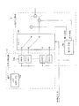
【0200】
本発明の表示装置は、図17に示す液晶表示装置12’のように、セレクタ2を備えていない構成であってもよい。この液晶表示装置12’において、液晶パネル7の素特性を測定する際には、図2の構成において信号発生器1から出力させたRGB各最高階調、白(W)最高階調、およびWの他の階調(0〜62階調)の各信号を、映像信号としてRGB非線形変換器3〜5に入力するとともに、RGB非線形変換器3〜5での変換を行わずに上記各信号がそのまま液晶駆動回路6に入力されるようにすればよい。
【0201】
したがって、本発明の表示装置としては、三原色信号(RGB信号等)からなる映像信号に補正を施し、補正後の信号に基づいて表示手段(液晶パネル7)にカラー映像を表示する表示装置であり、上述した補正特性決定装置(補正テーブル係数生成器9)にて決定される補正後の各階調値(補正値HR(i))を記憶するための記憶手段(補正テーブル設定制御装置10)と、この記憶手段に記憶された補正後の階調値に基づいて、上記映像信号を上記補正後の信号に変換する変換手段(RGB非線形変換器3〜5)とを備えておればよい。
【0202】
この表示装置では、上記補正特性決定装置によって補正特性を適正に決定することができるため、高品位の表示を実現することができる。
【0203】
また、この表示装置では、変換手段が、上記映像信号に応じて記憶手段に記憶された補正後の階調値を補間することにより上記補正後の信号を生成するようになっている。
【0204】
この構成では、図16の階調iとして採用する階調値I(i)以外の階調値を補間により算出することができる。そのため、上記階調iとして採用する階調値I(i)の数を減らしつつも高品位の表示を維持することができるようになり、記憶手段の容量、つまりメモリ10aやレジスタ10bの容量を削減することが可能になる。
【0205】
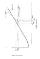
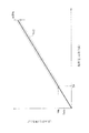
なお、液晶表示装置12や液晶表示装置12’では、図18に示すように、低階調部処理用閾値TH以上の階調値において、例えば、目標輝度特性データYoに対する、液晶パネル7での実際の出力輝度のばらつきが±5%以内(図18中破線で挟まれた範囲)に抑えることも可能である。このように、本発明の表示装置では、映像信号として中間階調値が入力された場合に、その中間階調値がある一定の値(低階調部処理用閾値TH)以上のとき、目標輝度特性データYoに対する、液晶パネル7での実際の出力輝度のばらつきが±5%以内とすることができる。
【0206】
また、低階調部処理用閾値THは、液晶表示装置12に最低階調の信号が入力された場合における液晶パネル7の出力輝度の10倍(さらに望ましくは100倍)以上の輝度を出力できるような階調に設定することが望ましい。つまり、図18において、Yth≧10×Ymin(さらに望ましくはYth≧100×Ymin)を満たすことが望ましい。
【0207】
【発明の効果】
本発明に係る補正特性決定装置は、表示手段の表示における発光状態の測定結果を三刺激値に変換可能な値で示したデータである測定データを、変換行列を用いて三原色の輝度データに変換するデータ変換手段と、変換結果に基づいて補正特性を決定する補正特性決定手段と、変換行列を生成する行列生成手段とを備え、行列生成手段は、変換行列の逆行列の行列要素を生成する行列要素生成手段と、行列要素生成手段により生成された行列要素を修正する行列要素修正手段と、修正された行列要素からなる行列の逆行列を生成する逆行列生成手段とを備える構成である。
【0208】
上記の構成では、行列生成手段が表示手段の特性にあった変換行列を生成することで、データ変換手段によるデータ変換を適正化することができる。その結果、データ変換の際のオーバーフローや変換誤差等を抑制することができ、補正特性決定手段による補正特性の決定をより正確にすることができるようになる。
【0209】
本発明に係る補正特性決定装置は、上記補正特性決定装置において、目標色度データを変換行列を用いて変換することで、三原色の出力輝度の混合比を生成する目標混合比生成手段を備え、補正特性決定手段は目標混合比に基づいて最高階調値に対応する目標出力輝度を決定する最高階調決定手段を備えることが望ましい。
【0210】
上記の構成では、三原色の出力輝度の正確な混合比を生成することができ、この混合比を用いて最高階調値に対応する目標出力輝度を決定することで、最高階調を正確な混合比に設定することができる。
【0211】
本発明に係る補正特性決定装置は、上記最高階調決定手段を備える補正特性決定装置において、上記最高階調決定手段は、輝度データが最も不足しているものをその原色信号の最高階調値に対応する目標出力輝度とし、この目標出力輝度を基準にして目標混合比に基づいて他の原色信号の最高階調値に対応する目標出力輝度を決定することが望ましい。
【0212】
上記の構成では、白の最高階調が目標混合比からずれた表示になることを回避することができる。
【0213】
本発明に係る補正特性決定装置は、上記最高階調決定手段を備える補正特性決定装置において、上記補正特性決定手段は、最高階調値に対応する目標出力輝度と、表示手段に対して設定された最高階調値に対応する目標出力輝度と中間階調値に対応する目標出力輝度との比率とに基づいて、中間階調値に対応する目標出力輝度を決定する中間階調決定手段を備えることが望ましい。
【0214】
上記の構成では、表示手段に対して設定された上記比率に応じた目標出力輝度を設定することができる。
【0215】
本発明に係る補正特性決定装置は、上記中間階調決定手段を備える補正特性決定装置において、階調値の変化に対する出力輝度の変化が相対的に小さい階調値の領域では、階調値の変化に対する出力輝度の変化が相対的に大きい階調値の領域より、上記中間階調値として採用する階調値の密度を大きくすることが望ましい。
【0216】
上記の構成では、上記中間階調値として採用する階調値(サンプリングポイント)以外の階調値を補間等により算出する場合に、限られた数のサンプリングポイントで適正な補間を行うことができる。
【0217】
本発明に係る補正特性決定装置は、上記中間階調決定手段を備える補正特性決定装置において、補正特性決定手段は、中間階調値に対応する目標出力輝度を修正する階調修正手段を備えることが望ましい。
【0218】
上記の構成では、表示手段における白の最低階調の表示(黒浮き)の特性を考慮して中間階調値に対応する目標出力輝度を修正することで、表示手段で実際に表示できないような目標出力輝度を設定することを回避できるようになる。
【0219】
本発明に係る補正特性決定装置は、上記階調修正手段を備える補正特性決定装置において、中間階調値に対応する目標出力輝度のうち少なくとも表示手段に表示可能な輝度に満たない輝度を目標出力輝度としている階調に対応する目標出力輝度から、修正パラメータを引くことで修正を行うことが望ましい。
【0220】
上記の構成では、白の最低階調に対応する目標出力輝度を、表示手段で実際に表示できる最低の出力輝度に合わせることができる。表示手段で実際に表示できる低階調領域を有効に利用しつつ、実際に表示できないような目標出力輝度を設定することを回避できるようになる。
【0221】
本発明に係る補正特性決定装置は、上記修正パラメータを引くことで修正を行う補正特性決定装置において、階調修正手段は、中間階調値のうち、修正を行うべき階調値の上限として設定された閾値未満の中間階調値において上記修正を行うことが望ましい。
【0222】
上記の構成では、閾値を適切に設定することにより、目標出力輝度を修正する領域から修正しない領域への移行をスムーズにすることができ、表示手段で暗い映像を表示したときにわずかな階調の違いで色味や輝度が大きく変化することを抑えることができる。
【0223】
本発明に係る補正特性決定装置は、上記中間階調決定手段を備える補正特性決定装置において、決定した最高階調値および中間階調値に対応する補正後の階調値を決定する階調値変換手段を備えることが望ましい。
【0224】
上記の構成では、映像信号の階調値と、その階調値に対応する補正後の階調値との対応関係を決定することができる。この対応関係を表示装置に提供することにより、表示装置にて容易に補正を行うことができるようになる。
【0225】
なお、本発明に係る上記各補正特性決定装置は、それぞれ補正特性決定方法としても捉えることができる。
【0226】
また、本発明に係る表示装置は、三原色信号からなる映像信号に補正を施し、補正後の信号に基づいて表示手段にカラー映像を表示する表示装置であって、上記各補正特性決定方法によって補正特性が決定されているものである。上記の表示装置では、上記各補正特性決定方法によって補正特性を適正に決定することができるため、高品位の表示を実現することができる。
【0227】
また、本発明に係る表示装置は、階調値変換手段を備える補正特性決定装置にて決定される補正後の各階調値を記憶するための記憶手段と、記憶手段に記憶された補正後の階調値に基づいて、映像信号を補正後の信号に変換する変換手段とを備える構成である。
【0228】
上記の表示装置では、上記補正特性決定装置によって補正特性を適正に決定することができるため、高品位の表示を実現することができる。
【0229】
本発明に係る表示装置は、上記の表示装置において、変換手段は、映像信号に応じて記憶手段に記憶された補正後の階調値を補間することにより補正後の信号を生成することが望ましい。
【0230】
上記の構成では、上記複数の中間階調値として採用する階調値以外の階調値を補間により算出することができる。そのため、上記複数の中間階調値として採用する階調値の数を減らしつつも高品位の表示を維持することができるようになり、記憶手段の容量を削減することが可能になる。
【0231】
本発明に係る補正特性決定装置は、補正前の映像信号の階調値と、その階調値に対して上記表示手段にて表示すべき目標出力輝度との対応関係を表す目標値曲線を設定する目標値曲線設定手段と、目標値曲線における映像信号の最低階調値に対応する最低目標出力輝度から、表示手段が最低階調を表示したときの実際の輝度の値を引くことで修正パラメータを設定するとともに、目標値曲線における目標出力輝度のうち少なくとも最低目標出力輝度未満の目標出力輝度から、修正パラメータを引くことで目標値曲線を修正する階調修正手段と、階調修正手段にて修正された目標値曲線に基づいて、映像信号における補正前の階調値と補正後の階調値との関係を決定する階調値変換手段とを備える構成である。
【0232】
上記の構成では、表示手段で実際に表示できる低階調領域を有効に利用しつつ、実際に表示できないような目標出力輝度を設定することを回避できるようになる。
【0233】
本発明に係る補正特性決定装置は、上記の補正特性決定装置において、階調修正手段は、上記修正を行うべき階調値の上限として設定された閾値未満の階調値において修正を行うことが望ましい。
【0234】
上記の構成では、閾値を適切に設定することにより、目標出力輝度を修正する領域から修正しない領域への移行をスムーズにすることができ、表示手段で暗い映像を表示したときにわずかな階調の違いで色味や輝度が大きく変化することを抑えることができる。
【0235】
また、本発明に係る補正特性決定方法は、補正前の映像信号の階調値と、その階調値に対して表示手段にて表示すべき目標出力輝度との対応関係を表す目標値曲線を設定する目標値曲線設定処理と、目標値曲線における映像信号の最低階調値に対応する最低目標出力輝度から、表示手段が最低階調を表示したときの実際の輝度の値を引くことで修正パラメータを設定するとともに、目標値曲線における目標出力輝度のうち少なくとも最低目標出力輝度未満の目標出力輝度から、修正パラメータを引くことで目標値曲線を修正する階調修正処理と、階調修正処理にて修正された目標値曲線に基づいて、映像信号における補正前の階調値と補正後の階調値との関係を決定する階調値変換処理とを含む方法である。
【0236】
本発明に係る補正特性決定方法は、上記の補正特性決定方法において、階調修正処理は、上記修正を行うべき階調値の上限として設定された閾値未満の階調値において修正を行うことが望ましい。
【0237】
さらに、本発明に係る表示装置は、映像信号に補正を施し、補正後の信号に基づいて表示手段に映像を表示する表示装置であって、上記の補正特性決定方法によって補正特性が決定されている構成である。
【図面の簡単な説明】
【図1】本発明の実施の一形態に係る補正テーブル係数生成器の目標値設定部の構成を示すブロック図である。
【図2】本発明の実施の一形態に係るγ補正装置を備えた液晶表示装置、およびγ補正装置の補正テーブルを設定するための周辺装置(信号発生器、輝度・色度計、補正テーブル係数生成器)を示すブロック図である。
【図3】図2の補正テーブル係数生成器における処理の流れを示すフローチャートである。
【図4】図1の目標値設定部に含まれる変換マトリクス生成器の構成を示すブロック図である。
【図5】図1の目標値設定部に含まれる色度調整器の構成を示すブロック図である。
【図6】図1の目標値設定部に含まれるRGB補正目標値設定器の構成を示すブロック図である。
【図7】図6のRGB補正目標値設定器に含まれるRGB目標値(最高階調)設定器の構成を示すブロック図である。
【図8】図6のRGB補正目標値設定器に含まれるRGB目標値(64階調)設定器の構成を示すブロック図である。
【図9】図1の目標値設定部に含まれる低階調部目標値修正器の処理の流れを示すフローチャートである。
【図10】(a)はパネル素特性と目標値曲線との関係を示すグラフ、(b)は目標値曲線の修正の一例を示すグラフ、(c)は目標値曲線の修正の他の例を示すグラフである。
【図11】図1の目標値設定部に含まれる低階調部目標値修正器の構成を示すブロック図である。
【図12】補正テーブル係数生成部により補正テーブル係数を生成する処理の流れを示すフローチャートである。
【図13】図12の処理の内容を説明するためのグラフである。
【図14】図2に示した液晶表示装置の補正テーブル設定制御装置およびR非線形変換器の構成を示すブロック図である。
【図15】液晶パネルのV−T特性を示すグラフである。
【図16】階調と階調値と目標輝度との関係を示す図表である。
【図17】本発明の実施の一形態に係る液晶表示装置の構成を示すブロック図である。
【図18】図17の液晶表示装置における実際の出力輝度の分布範囲を示すグラフである。
【符号の説明】
3 R非線形変換器(変換手段)
4 G非線形変換器(変換手段)
5 B非線形変換器(変換手段)
7 液晶パネル(表示手段)
9 補正テーブル係数生成器
9a 目標値設定部
9b 補正テーブル係数生成部(階調値変換手段)
10 補正テーブル設定制御装置(記憶手段)
12 液晶表示装置(表示装置)
101 変換マトリクス生成器(行列生成手段)
102 色度調整器(目標混合比生成手段)
103 RGB補正目標値設定器(目標値曲線設定手段)
104 低階調部目標値修正器(補正特性決定手段、階調修正手段)
201〜204 行列要素生成手段
205 行列要素修正手段
206 逆行列計算手段(逆行列生成手段)
401 変換手段(データ変換手段)
402 RGB目標値(最高階調)設定器(補正特性決定手段、最高階調決定手段)
403 RGB目標値(64階調)設定器(補正特性決定手段、中間階調決定手段)[0001]
BACKGROUND OF THE INVENTION
The present invention relates to a correction characteristic determination device, a correction characteristic determination method, and a correction characteristic determination method for determining a correction characteristic of correction performed on a video signal in order to improve display quality of a display device such as a liquid crystal panel. This relates to a display device for which correction characteristics are determined.
[0002]
[Prior art]
In recent years, various color liquid crystal display devices (liquid crystal color displays) have been developed and marketed. In order to improve the display quality of the liquid crystal panel, the liquid crystal display device includes a γ correction device that performs γ correction on an input video signal. There is a need for a correction characteristic determination device that can appropriately determine the correction characteristic of the γ correction.
[0003]
Conventionally, as a technique related to γ correction of a liquid crystal display device, there is a technique disclosed in Japanese Patent Application Laid-Open No. 5-127620. The technology disclosed in this publication discloses that in a projection-type liquid crystal display device, the luminance and chromaticity of an actually projected image is measured, and γ correction is performed while adjusting the white balance to the target chromaticity. Yes.
[0004]
[Problems to be solved by the invention]
However, in the technique disclosed in Japanese Patent Laid-Open No. 5-127620, when adjusting the white balance, the RGB target mixing ratio is obtained from the preset target chromaticity and the actually measured chromaticity. However, the characteristics of individual display devices are not taken into account in the calculation for obtaining the target mixture ratio of RGB. More specifically, in the technique disclosed in the above publication, the RGB target mixture ratio is calculated using the chromaticity when each RGB single color is projected, but the chromaticity in the case of white display is considered. Therefore, the target mixture ratio of RGB is calculated without reflecting the luminance variation between RGB in the actual display device.
[0005]
For this reason, in the technique disclosed in the above publication, even when the display is performed by the display device after correction, the target mixture ratio of RGB is still deviated from each other due to variations in individual display devices.
[0006]
Further, the technique disclosed in the above publication does not take into account the black floating characteristic of the liquid crystal element in the low gradation part, so that a target value curve (output with respect to the gradation value) as shown in FIG. The curve representing the target luminance value may be a value that cannot be displayed on the liquid crystal element.
[0007]
For example, even if the target value indicated by the target value curve is “0” in the lowest gradation portion, when the lowest gradation is actually displayed on the liquid crystal element and the luminance and chromaticity at that time are measured, a slight luminance is obtained.・ There may be chromaticity. Therefore, the target value “0” is a value that cannot be displayed on the liquid crystal element. In order to set a target value that can be displayed, it is necessary to correct the target value in the low gradation portion.
[0008]
Furthermore, when the target value in the low gradation part is corrected, the target value in the medium to high gradation part is not changed from the corrected target value in the low gradation part as shown in FIG. 10B. If it does not change smoothly (as in FIG. 10C), the luminance and chromaticity may change greatly in the vicinity of the gradation in the display on the display device after correction, resulting in poor quality video. .
[0009]
The present invention has been made in view of the above-described problems of the prior art, and an object of the present invention is to display the correction characteristics on a display device that corrects the video signal and displays the video on the display means. It is an object of the present invention to provide a correction characteristic determining apparatus and a correction characteristic determining method for meeting the characteristics of the means. Another object of the present invention is to provide a display device whose correction characteristics are determined by such a correction characteristic determination method.
[0010]
[Means for Solving the Problems]
A correction characteristic determination apparatus according to the present invention is a correction characteristic determination apparatus that corrects a video signal including three primary color signals and determines correction characteristics in a display device that displays a color video on a display unit based on the corrected signal. In order to solve the above-mentioned problem, the measurement data, which is data indicating the measurement result of the light emission state in the display of the display means as a value that can be converted into tristimulus values, Data conversion means for converting to data, correction characteristic determination means for determining the correction characteristics based on the conversion result by the data conversion means, and matrix generation means for generating the conversion matrix, the matrix generation means, Matrix element generating means for generating a matrix element of an inverse matrix of the conversion matrix based on measurement data when the display means displays the highest gradation of each primary color; and the display means A matrix element correction unit that corrects the matrix element generated by the matrix element generation unit based on the measurement data when the highest gray level is displayed, and an inverse matrix of the matrix including the corrected matrix element are generated. And an inverse matrix generation means.
[0011]
In the above configuration, the measurement data is converted into the luminance data of the three primary colors by the data conversion means, so that the characteristics of the display means of the display device can be grasped by the luminance data of the three primary colors. The correction characteristic determining means can determine a desired correction characteristic based on the three primary color luminance data.
[0012]
The measurement data is data indicating the measurement result of the light emission state on the display of the display means as a value that can be converted into a tristimulus value, and can be obtained from a measurement means such as a luminance / colorimeter. The “value that can be converted into tristimulus values” may be tristimulus values themselves such as X, Y, and Z in the XYZ color system, and may be Y, x, and y in the Yxy color system. Thus, it may be a value having a correlation with the tristimulus value.
[0013]
The correction characteristic is determined as a relationship between the gradation value of the video signal and an appropriate value (target output luminance) as the actual output luminance in the display means when the gradation value is input to the display device. The
[0014]
Here, the conversion matrix used for data conversion by the data conversion means is generated by the matrix generation means. The matrix generation means generates a transformation matrix by the matrix element generation means, the matrix element correction means, and the inverse matrix generation means.
[0015]
The matrix element generation unit can generate the matrix element of the inverse matrix of the transformation matrix because
[0016]
The matrix element correction means creates
[0017]
The inverse matrix generation means can generate the transformation matrix by generating an inverse matrix of the matrix composed of the matrix elements corrected by the matrix element correction means.
[0018]
As described above, the matrix generation unit generates the conversion matrix suitable for the characteristics of the display unit, so that the data conversion by the data conversion unit can be optimized. As a result, it is possible to suppress overflow, conversion error, and the like during data conversion, and it is possible to make correction characteristic determination by the correction characteristic determination unit more accurate.
[0019]
The correction characteristic determination apparatus according to the present invention is the correction characteristic determination apparatus, wherein in the correction characteristic determination apparatus, target chromaticity data indicating a target chromaticity as a value that can be converted into a tristimulus value for setting the chromaticity of display on the display means Is converted using the conversion matrix to generate a target mixture ratio generation unit that generates a mixture ratio of output luminances of the three primary colors, and the correction characteristic determination unit displays the highest white gradation in the display unit. Determination of the maximum gradation for determining the target output luminance corresponding to the maximum gradation value of each primary color signal in the video signal based on the result of converting the measured data by the data conversion means and the target mixture ratio It is desirable to provide means.
[0020]
In the above configuration, the target mixture ratio generation unit converts the target chromaticity data into luminance data of the three primary colors using the conversion matrix, and generates a mixture ratio of the output luminances of the three primary colors. The target chromaticity data is input to the correction characteristic determination device from the outside, for example. In this way, by converting the target chromaticity data using the conversion matrix that matches the characteristics of the display means, the luminance data of the three primary colors is prevented from deviating from the original value, and the accurate mixing ratio of the output luminance of the three primary colors is suppressed. Can be generated. By using this mixing ratio, the highest gradation determining means determines the target output luminance corresponding to the highest gradation value of each primary color signal in the video signal, so that the highest gradation can be set to an accurate mixing ratio.
[0021]
The correction characteristic determination apparatus according to the present invention is the correction characteristic determination apparatus including the highest gradation determination means, wherein the highest gradation determination means uses the measurement data when the display means displays the highest gradation of white as described above. Based on the ratio of the luminance data of each primary color in the result of conversion by the data conversion means and the target mixing ratio, the target output corresponding to the highest gradation value of the primary color signal is the one with the shortest luminance data. It is desirable to determine the target output luminance corresponding to the highest gradation value of the other primary color signals based on the target mixture ratio with reference to the target output luminance.
[0022]
In the above configuration, the target output luminance of the primary color other than the reference primary color is equal to or lower than the luminance data of the conversion result. Therefore, in any primary color, the problem that the luminance that cannot actually be displayed by the display means is determined as the target output luminance corresponding to the highest gradation value does not occur. Therefore, it is possible to avoid the display in which the maximum gray level of white is shifted from the target mixture ratio.
[0023]
The correction characteristic determining apparatus according to the present invention is the correction characteristic determining apparatus including the highest gradation determining means, wherein the correction characteristic determining means is the highest gradation value of each primary color signal determined by the highest gradation determining means. And a ratio of the target output luminance corresponding to the highest gradation value set for the display means and the target output luminance corresponding to each of the plurality of intermediate gradation values, It is desirable to provide intermediate gradation determining means for determining target output luminance corresponding to the plurality of intermediate gradation values of the primary color signal.
[0024]
In the above configuration, the target output corresponding to the highest gradation value set for the display means with reference to the target output luminance corresponding to the highest gradation value of each primary color signal determined by the highest gradation determination means. By determining the target output luminance corresponding to the plurality of intermediate gradation values of each primary color signal based on the ratio between the luminance and the target output luminance corresponding to each of the plurality of intermediate gradation values, the display means A target output luminance can be set according to the set ratio. Note that the ratio set for the display means is input to the correction characteristic determining apparatus from the outside, for example.
[0025]
The correction characteristic determination apparatus according to the present invention is the correction characteristic determination apparatus including the intermediate gradation determination unit, wherein the output with respect to the change of the gradation value in the relationship between the gradation value of each primary color signal and the output luminance in the display unit. In the gradation value region where the change in luminance is relatively small, the gradation value adopted as the plurality of intermediate gradation values than in the region of the gradation value in which the change in output luminance relative to the change in gradation value is relatively large It is desirable to increase the density.
[0026]
In the above configuration, when the gradation values other than the gradation values (sampling points) employed as the plurality of intermediate gradation values are calculated by interpolation or the like, proper interpolation can be performed with a limited number of sampling points. it can.
[0027]
The correction characteristic determination apparatus according to the present invention is the correction characteristic determination apparatus provided with the intermediate gradation determination means, wherein the correction characteristic determination means uses the measurement data when the display means displays the lowest white gradation as the data. Gradation correction means for correcting the target output luminance corresponding to the plurality of intermediate gradation values of each primary color signal determined by the intermediate gradation determination means based on the result of conversion by the conversion means; desirable.
[0028]
In the above configuration, the display means cannot be actually displayed by correcting the target output luminance corresponding to the intermediate gradation value in consideration of the characteristics of the display of the lowest gradation of white (black float) on the display means. Setting the target output brightness can be avoided.
[0029]
The correction characteristic determination apparatus according to the present invention is the correction characteristic determination apparatus including the gradation correction unit, wherein the plurality of intermediate gradation values include a minimum white gradation value, and the gradation correction unit includes: For the primary color signal, from the target output luminance corresponding to the white minimum gradation determined by the intermediate gradation determination means, measurement data when the display means displays the white minimum gradation is sent to the data conversion means. By subtracting the converted result, the correction parameter of the primary color signal is obtained, and at least the target output luminance corresponding to the plurality of intermediate gradation values of each primary color signal determined by the intermediate gradation determination means It is desirable to perform the correction by subtracting the correction parameter of the primary color signal from the target output luminance corresponding to the gradation whose luminance is less than the luminance that can be displayed on the display means.
[0030]
In the above configuration, the target output luminance corresponding to the lowest gray level of white can be matched with the lowest output luminance that can be actually displayed by the display means. It is possible to avoid setting a target output luminance that cannot be actually displayed while effectively using the low gradation region that can be actually displayed by the display means.
[0031]
The correction characteristic determination apparatus according to the present invention is a correction characteristic determination apparatus that performs correction by subtracting the correction parameter, wherein the gradation correction means is a gradation to be corrected among the plurality of intermediate gradation values. It is desirable to perform the above correction at an intermediate gradation value less than the threshold set as the upper limit of the value.
[0032]
In the above configuration, by appropriately setting the threshold value, the transition from the region for correcting the target output luminance to the region for no correction can be made smoothly, and a slight gradation is obtained when a dark image is displayed on the display means. It is possible to suppress a significant change in color and brightness due to the difference in color.
[0033]
The correction characteristic determination apparatus according to the present invention is the correction characteristic determination apparatus including the intermediate gradation determination means, wherein the target output luminance, the display means displays the highest white gradation value and the plurality of intermediate gradation values. The gradation that determines the corrected gradation value corresponding to the maximum gradation value of each primary color signal and the plurality of intermediate gradation values based on the result of conversion of the measured data by the data conversion means It is desirable to provide value conversion means.
[0034]
In the above configuration, the correspondence relationship between the gradation value of the video signal and the corrected gradation value corresponding to the gradation value can be determined. By providing this correspondence relationship to the display device, the display device can easily perform correction.
[0035]
Note that each of the correction characteristic determination devices according to the present invention can also be understood as a correction characteristic determination method. In the following correction characteristic determining methods, the same effects as those of the correction characteristic determining apparatuses can be obtained.
[0036]
That is, the correction characteristic determination method according to the present invention corrects a video signal composed of three primary color signals and determines a correction characteristic in a display device that displays a color video on a display unit based on the corrected signal. In order to solve the above-mentioned problem, the measurement data, which is data indicating the measurement result of the light emission state in the display of the display means as a value that can be converted into tristimulus values, is converted into the three primary colors using a conversion matrix. A data conversion process for converting to the luminance data, a correction characteristic determination process for determining the correction characteristic based on a conversion result by the data conversion process, and a matrix generation process for generating the conversion matrix before the data conversion process, The matrix generation processing generates a matrix element of an inverse matrix of the conversion matrix based on measurement data when the display means displays the highest gradation of each primary color. Matrix element generation processing, matrix element correction processing for correcting matrix elements generated by the matrix element generation processing based on measurement data when the display means displays the highest white gradation, and the corrected matrix And an inverse matrix generation process for generating an inverse matrix of an element matrix.
[0037]
Further, the correction characteristic determination method according to the present invention is a target color indicating a target chromaticity as a value that can be converted into a tristimulus value in order to set a display chromaticity in the display means in the correction characteristic determination method. Degree data is converted using the conversion matrix, thereby generating a target mixture ratio generation process for generating a mixture ratio of output luminances of the three primary colors. Based on the result obtained by converting the measurement data at the time of display by the data conversion process and the target mixture ratio, the highest order level for determining the target output luminance corresponding to the highest gradation value of each primary color signal in the video signal. It is desirable to include a key determination process.
[0038]
The correction characteristic determination method according to the present invention is a correction characteristic determination method including the highest gradation determination process, wherein the highest gradation determination process includes measurement data obtained when the display means displays the highest white gradation. Based on the luminance data ratio of each primary color in the result of conversion by the above data conversion processing and the target mixing ratio, the one having the least luminance data corresponds to the highest gradation value of the primary color signal. It is desirable that the target output luminance is determined, and the target output luminance corresponding to the highest gradation value of the other primary color signals is determined based on the target mixture ratio with reference to the target output luminance.
[0039]
The correction characteristic determination method according to the present invention is a correction characteristic determination method including the highest gradation determination process, wherein the correction characteristic determination process is the highest order of each primary color signal determined by the highest gradation determination means. Based on the target output luminance corresponding to the tone value and the ratio of the target output luminance corresponding to the highest gradation value set for the display means and the target output luminance corresponding to each of the plurality of intermediate gradation values It is desirable to include an intermediate gradation determination process for determining a target output luminance corresponding to the plurality of intermediate gradation values of each primary color signal.
[0040]
The correction characteristic determination method according to the present invention is the correction characteristic determination method including the intermediate gradation determination process, wherein the gradation value changes in the relationship between the gradation value of each primary color signal and the output luminance in the display means. In the gradation value region in which the change in output luminance with respect to the tone value is relatively small, the gradation value adopted as the plurality of intermediate gradation values is higher than the gradation value region in which the change in output luminance with respect to the change in gradation value is relatively large. It is desirable to increase the density of tone values.
[0041]
Further, the correction characteristic determination method according to the present invention is the correction characteristic determination method including the intermediate gradation determination process, wherein the correction characteristic determination process includes measurement data obtained when the display means displays the lowest white gradation. A tone correction process for correcting a target output luminance corresponding to the plurality of intermediate tone values of each primary color signal determined in the intermediate tone determination process based on the result of conversion in the data conversion process; It is desirable.
[0042]
The correction characteristic determination method according to the present invention is the correction characteristic determination method including the gradation correction process, wherein the plurality of intermediate gradation values include a minimum white gradation value. For each primary color signal, from the target output luminance corresponding to the lowest white gradation determined in the intermediate gradation determination process, the measurement data when the display means displays the lowest white gradation is converted to the data. By subtracting the result of conversion in the process, the correction parameter of the primary color signal is obtained, and among the target output luminances corresponding to the plurality of intermediate gradation values of each primary color signal determined in the intermediate gradation determination process It is desirable to perform correction by subtracting the correction parameter of the primary color signal from the target output luminance corresponding to the gradation having the target output luminance that is at least the luminance that can be displayed on the display means.
[0043]
The correction characteristic determination method according to the present invention is a correction characteristic determination method in which correction is performed by subtracting the correction parameter. In the gradation correction processing, the correction should be performed among the plurality of intermediate gradation values. It is desirable to perform the above correction at an intermediate gradation value less than the threshold value set as the upper limit of the gradation value.
[0044]
The correction characteristic determination method according to the present invention is the correction characteristic determination method in which correction is performed by subtracting the correction parameter. In the correction characteristic determination method including the intermediate gradation determination process, the target output luminance and the display Based on the result obtained by converting the measurement data when the means displays the white maximum gradation value and the plurality of intermediate gradation values in the data conversion process, the maximum gradation value of each primary color signal and the plurality of the plurality of intermediate gradation values are displayed. A gradation value conversion process for determining a corrected gradation value corresponding to the intermediate gradation value is included.
[0045]
Furthermore, the display device according to the present invention is a display device that corrects a video signal composed of three primary color signals and displays a color video on the display means based on the corrected signal, and corrects by the above correction characteristic determination methods. The characteristic is determined.
[0046]
In the above display device, the correction characteristics can be appropriately determined by the above-described correction characteristic determination methods, so that high-quality display can be realized.
[0047]
The display device according to the present invention is a display device that corrects a video signal composed of three primary color signals and displays a color video on a display unit based on the corrected signal, and includes the gradation value conversion unit. A storage means for storing each gradation value after correction determined by the correction characteristic determination device, and the video signal after the correction based on the gradation value after correction stored in the storage means It is characterized by comprising a conversion means for converting to.
[0048]
In the display device described above, the correction characteristic can be appropriately determined by the correction characteristic determination device, so that high-quality display can be realized.
[0049]
In the display device according to the present invention, in the display device, the conversion unit generates the corrected signal by interpolating the corrected gradation value stored in the storage unit according to the video signal. It is desirable to do.
[0050]
In the above configuration, tone values other than the tone values employed as the plurality of intermediate tone values can be calculated by interpolation. For this reason, it is possible to maintain a high-quality display while reducing the number of gradation values employed as the plurality of intermediate gradation values, and it is possible to reduce the capacity of the storage means.
[0051]
A correction characteristic determination apparatus according to the present invention is a correction characteristic determination apparatus that determines a correction characteristic in a display device that corrects a video signal and displays a video on a display unit based on the corrected signal. In order to solve this problem, a target value curve for setting a target value curve representing the correspondence between the gradation value of the video signal before correction and the target output luminance to be displayed on the display means with respect to the gradation value The correction parameter is set by subtracting the actual brightness value when the display means displays the lowest gradation from the setting means and the lowest target output brightness corresponding to the lowest gradation value of the video signal in the target value curve. And a tone correction means for correcting the target value curve by subtracting the correction parameter from a target output luminance less than the minimum target output luminance among the target output luminances in the target value curve. Gradation value conversion means for determining a relationship between the gradation value before correction and the gradation value after correction in the video signal based on the target value curve corrected by the gradation correction means. It is said.
[0052]
In the above configuration, by correcting the target output brightness in consideration of the characteristics of the lowest gradation display (black floating) on the display means, setting the target output brightness that cannot be actually displayed on the display means is avoided. become able to. At this time, in the above configuration, the lowest target output luminance corresponding to the lowest gradation can be matched with the lowest output luminance that can be actually displayed by the display means. This makes it possible to avoid setting a target output luminance that cannot be actually displayed while effectively using the low gradation region that can be actually displayed by the display means.
[0053]
In the correction characteristic determination apparatus according to the present invention, in the correction characteristic determination apparatus, the gradation correction unit performs the correction on a gradation value less than a threshold set as an upper limit of the gradation value to be corrected. It is desirable.
[0054]
In the above configuration, by appropriately setting the threshold value, the transition from the region for correcting the target output luminance to the region for no correction can be made smoothly, and a slight gradation is obtained when a dark image is displayed on the display means. It is possible to suppress a significant change in color and brightness due to the difference in color.
[0055]
The correction characteristic determination method according to the present invention is a correction characteristic determination method for determining a correction characteristic in a display device that corrects a video signal and displays a video on a display unit based on the corrected signal. A target value curve setting process for setting a target value curve representing a correspondence relationship between the gradation value of the previous video signal and the target output luminance to be displayed on the display means with respect to the gradation value; and the target value The correction parameter is set by subtracting the actual luminance value when the display means displays the lowest gradation from the lowest target output luminance corresponding to the lowest gradation value of the video signal in the curve, and the target value curve In the tone correction processing for correcting the target value curve by subtracting the correction parameter from the target output luminance less than the minimum target output luminance among the target output luminances in FIG. Tadashisa a on the basis of the target value curve is characterized by comprising a gradation-value conversion process of determining the relationship between the gradation value and the corrected tone value prior to correction in the video signal.
[0056]
The correction characteristic determination method according to the present invention is the correction characteristic determination method described above. In the correction characteristic determination method, the gradation correction process performs the correction on a gradation value less than a threshold set as an upper limit of the gradation value to be corrected. It is desirable.
[0057]
Furthermore, the display device according to the present invention is a display device that corrects a video signal and displays a video on a display unit based on the corrected signal, and the correction characteristic is determined by the correction characteristic determination method described above. It is characterized by being.
[0058]
DETAILED DESCRIPTION OF THE INVENTION
An embodiment of the present invention will be described below with reference to FIGS.
[0059]
1. overall structure
FIG. 2 is a block diagram illustrating a liquid
[0060]
The correction table of the
[0061]
Here, the RGB video signals input to the liquid
[0062]
The gradation i for 64 gradations and the gradation value I (i) for 256 gradations are associated with each other as shown in FIG. In the following, “gradation” means a value for 64 gradations, and “gradation value” means a value for 256 gradations.
[0063]
The correspondence between the gradation i and the gradation value I (i) is determined as follows. When a gradation value (proportional to the voltage applied to the liquid crystal) is input, the VT characteristic before the γ correction of the liquid crystal panel 7 (the transmittance (T) with respect to the applied voltage (V) in the liquid crystal panel 7) The characteristics and transmittance can be taken as luminance) as shown in FIG. Here, in the areas A and E in FIG. 15, since the change in output luminance due to the change in the gradation value is small, a large number of gradation values I (i) (sampling points) adopted as the gradation i are taken. It is desirable to set the key i finely. Conversely, in a region such as C where the output luminance varies greatly with the change in gradation value, the gradation value I (i) (sampling point) may be small. In this way, as shown in FIG. 16, it is possible to set a gradation i with a large number of sampling points in the low gradation area and the high gradation area and a small sampling point in the intermediate gradation area. Note that the gradation value I (0) corresponding to the 0th gradation which is the lowest gradation is set to 0 which is the lowest gradation value, and the gradation value I (63) corresponding to the 63th gradation which is the highest gradation. Is set to 255 which is the maximum gradation value.
[0064]
When setting the correction table, first, in order to measure the elementary characteristics of the
[0065]
Next, the signal output from the
[0066]
FIG. 16 is a chart illustrating an example of the target luminance characteristic data Yo. The target luminance characteristic data Yo is data for determining a target value (target luminance) of luminance at each gradation. FIG. 16 shows the gradation i in the case of γ = 2.2, the gradation value I (i) corresponding to each gradation, and the target luminance Yo (i) of each gradation (the luminance of 63 gradations is 100%). Relative value). As described above, the target luminance Yo (i) indicates a value at the i gradation of the target γ curve. Note that the relationship between the gradation i and the gradation value I (i) in FIG. 16 is set in, for example, the correction table
[0067]
The target chromaticities xo and yo are values for adjusting the white balance. The target chromaticities xo and yo are values of x and y in the Yxy color system in a state where the white balance is appropriately adjusted in all the W gradations excluding a low gradation part to be described later.
[0068]
The low gradation portion processing threshold TH is a threshold for setting up to which gradation the low gradation portion is to be set.
[0069]
The correction table
[0070]
2. Process flow in the correction table coefficient generator
FIG. 3 is a flowchart showing the flow of processing in the correction
[0071]
Next, a conversion matrix for converting Yxy color system data into RGB color system data based on the data input in step S20, which is suitable for the panel characteristics of the
[0072]
Next, an RGB target mixture ratio for adjusting chromaticity is generated based on the conversion matrix generated in step S21 and the preset target chromaticity xo, yo (step S22).
[0073]
Next, using the conversion matrix generated in step S21, the Yxy color system data input in step S20 is converted into RGB color system data (step S23).
[0074]
Next, based on the target mixture ratio generated in step S22, the data converted in step S23, and the preset target luminance characteristic data Yo, target values for each gradation of each RGB color are set ( Step S24).
[0075]
Next, the target value of the low gradation part is corrected based on the data converted in step S23, the target value set in step S24, and the preset threshold value TH for the low gradation part. (Step S25).
[0076]
Then, a correction table coefficient is generated based on the target value set in steps S21 to S24 and the original characteristics of the panel (step S26), and the correction table coefficient is output (step S27).
[0077]
3. Target value setting section
In the correction
[0078]
FIG. 1 is a block diagram showing the configuration of the target
[0079]
The
[0080]
The target chromaticity xo, yo is input to the
[0081]
The low gradation part
[0082]
The
Hereinafter, each part of FIG. 1 will be described in more detail.
[0083]
3-1. Transformation matrix generator
The
[0084]
The matrix element generation means 201 to 204 are input with the measurement value data from the luminance /
[0085]
Each of the matrix
RX = RY × Rx / Ry
RZ = RY × (1-Ry−Rx) / Ry
GX = GY × Gx / Gy
GZ = GY × (1−Gy−Gx) / Gy
BX = BY × Bx / By
BZ = BY × (1-By−Bx) / By
WX = WY (63) × Wx (63) / Wy (63)
WZ = WY (63) × (1-Wy (63) −Wx (63)) / Wy (63)
Note that the luminances RY, GY, BY of the Yxy color system and the luminances RY, GY, BY of the XYZ color system are the same. RX, RY, RZ, GX, GY, GZ, BX, BY, BZ, and WX, WY (63), WZ are XYZ tables when the highest gradations of RGB and W are displayed, respectively. Tristimulus values in the color system.
[0086]
Here, R, G, B of the RGB color system and X, Y, Z of the XYZ color system generally use the above RX, RY, RZ, GX, GY, GZ, BX, BY, BZ. Can be expressed as shown in
[0087]
[Expression 1]
However, in reality, there are variations in the characteristics of the individual
[0089]
[Expression 2]
The reason why the coefficient is set for each column in
[0091]
Therefore,
[0092]
[Equation 3]
[Expression 4]
Here, the following factors can be considered as the causes that the coefficients k, l, and m are not necessarily 1. For example, when displaying the highest R gradation and when displaying the highest W gradation, the same gradation value is input to the liquid
[0095]
Although there is no guarantee that the measured value data obtained when displaying the W highest gradation is the most correct, the correction
[0096]
As described above, the matrix
[0097]
Further, the matrix shown in
[0098]
[Equation 5]
3-2. Chromaticity adjuster
The
[0100]
The elements of the matrix (formula 5) generated by the
[0101]
Here, when Tx = xo, Ty = yo, and Tz = 1−Tx−Ty, the
RH = X1 * Tx + Y1 * Ty + Z1 * Tz
GH = X2 * Tx + Y2 * Ty + Z2 * Tz
BH = X3 * Tx + Y3 * Ty + Z3 * Tz
This calculation is an operation for converting the product of the matrix of
[0102]
3-3. RGB correction target value setter
6 includes a conversion unit 401 (Yxy → RGB conversion unit), an RGB target value (maximum gradation)
[0103]
The
[0104]
The conversion means 401 uses the conversion matrix (formula 5) generated by the
[0105]
This conversion is based on
[0106]
[Formula 6]
Here,
[0108]
Further, as shown in FIG. 6, the RGB target value (maximum gradation)
[0109]
The RGB target value (maximum gradation)
[0110]
The RGB target value (maximum gradation)
[0111]
A method for determining which of R (63), G (63), and B (63) is used as a reference will be described. Assume that R (63) is used as a reference. At this time, the maximum gradation target values of the RGB colors are R (63), R (63) × GH / RH, and R (63) × BH / RH, respectively. Here, when (R (63) × GH / RH)> G (63) or (R (63) × BH / RH)> B (63), the maximum gradation target value of G or B is the liquid crystal panel. 7 exceeds the value that can be displayed, and the
[0112]
Since the highest gradation target value obtained when at least one of R (63), G (63), and B (63) is used as a reference should be a value that can be displayed on the
[0113]
An internal configuration of the RGB target value (maximum gradation)
[0114]
The configuration in FIG. 7 includes a multiplier, a divider, a comparator, an AND circuit, and a
[0115]
In the selected
[0116]
In the
[0117]
Then, the
[0118]
The
[0119]
The AND
[0120]
Further, as shown in FIG. 6, the RGB target value (64 gradations)
[0121]
The RGB target value (64 gradations)
[0122]
FIG. 8 shows an internal configuration of the RGB target value (64 gradation)
[0123]
TRmax and TRmax × Yo (i) / Yo (63) are input to the selected
[0124]
A clock pulse count value i of the clock signal CLK by the
[0125]
When the count value i = i1 is input to the
[0126]
When the count value i input to the
[0127]
Here, the ratio of the target value TR (i) for i gradation and the target value TR (63) for maximum gradation, the target brightness Yo (i) for i gradation, and the target brightness Yo (63) for maximum gradation. And the ratio becomes equal. Therefore, the curve represented by the target value TR (0 to 63) is a curve having the same tendency as the curve represented by the target luminance Yo (0 to 63) with the maximum gradation being TRmax. That is, the target value TR (0 to 63) is TRmax in which the maximum gradation is set by the RGB target value (maximum gradation)
[0128]
3-4. Low gradation target value corrector
FIG. 9 is a flowchart showing the flow of processing in the low gradation part
[0129]
10 (a) to 10 (c) show the luminance (in the case of performing display based on the gradation input to the
[0130]
The low gradation part
[0131]
Then, the gradation i is set to an initial value 0 (step S32), and correction parameters DR, DG, and DB are obtained (step S33). The correction parameters DR, DG, DB are the target values TR (0), TG at the lowest gradation of the target value curve (see FIG. 10A) set by the RGB target value (64 gradation)
[0132]
If the gradation i is smaller than the low gradation portion processing threshold TH (step S34), the target values TR (i) and TG (i) set by the RGB target value (64 gradations)
[0133]
Here, at the 0th gradation, the panel element characteristic becomes the correction target value as it is, and a value that can be displayed on the
[0134]
Note that the gradation to be specifically set as the low gradation portion processing threshold TH may be set by confirming the actual display. For example, the target value is 10 times the value of the correction parameter (preferably It is preferable to set a gradation that is equal to or greater than (100 times) to the threshold value TH for low gradation part processing.
[0135]
The internal configuration of the low gradation part
[0136]
The
[0137]
TR (i) and TR (i)-(TR (0) -R (0)) are input to the selected
[0138]
When the count value i of the clock pulse of the clock signal CLK by the
[0139]
When a value (1 or 0) based on the count value i = i1 is input to the
[0140]
In the
[0141]
The
[0142]
In the present embodiment, the low gradation portion
[0143]
4). Correction table coefficient generator
The process of generating the correction table coefficient by the correction table coefficient generation unit 9b based on the correction target value and the non-correction target value set as described above is as shown in FIG. In this process, a correction value (correction input value) HR (i), which is a gradation value to be input to the liquid
[0144]
FIG. 12 is a flowchart showing the flow of processing in the correction table coefficient generation unit 9b. FIG. 13 is a graph for explaining the contents of the processing of FIG.
[0145]
In the correction table coefficient generation unit 9b, R (0 to 63) which is a conversion result by the
[0146]
Then, the gradation i is set to an initial value 0 (step S42), and based on R (0 to 63) and TTR (0 to 63),
R (j) ≦ TTR (i) and TTR (i) ≦ R (j + 1)
Search for j satisfying (step S43). Then, based on
[0147]
[Expression 7]
This process is repeated from the 0th gradation to the 63rd gradation (steps S43 to S46). Then, the obtained correction value HR (0 to 63) is output to the correction table setting control apparatus 10 (see FIG. 2) (step S47). Note that since the process of FIG. 12 is a well-known linear interpolation process, description of a circuit configuration that performs this process is omitted.
[0149]
5. Correction table setting control device, RGB nonlinear converter
FIG. 14 is a block diagram illustrating configurations of the correction table
[0150]
When a video signal is actually input, the following conversion is performed by the R
[0151]
The
[0152]
The weight calculation unit 3b calculates first and second weight coefficients for linearly interpolating the output values of the first and second outputs of the
1- (97-96) / (100-96) = 0.75 (8)
1- (100-97) / (100-96) = 0.25 (9)
Then, the output values of the first and second outputs are multiplied by the first and second weighting coefficients, respectively, and the multiplication results are added by the adder. The calculation result is output to the selector 2 (see FIG. 2). In the above example, this calculation is as shown in
HR (30) × 0.75 + HR (31) × 0.25 (10)
By the above method, a target curve is set from the original characteristics of the panel, a correction table is generated based on the target curve, and γ correction is performed on the panel.
[0153]
6). Summary
As described above, the liquid
[0154]
(1) The correction table coefficient generator 9 (see FIG. 1) according to the present embodiment generates a target
[0155]
(2) The conversion matrix generator 101 (see FIG. 4) considers the difference in display characteristics of the individual
[0156]
(3) The matrix element generation unit 201 (see FIG. 4) calculates the highest gradation of each color of RGB based on the relationship (X: Y: Z) = (x: y: (1-xy)). Yxy color system measurement values (RY, Rx, Ry, GY, Gx, Gy, BY, Bx, By) when displayed on the
[0157]
(4) The matrix element correction unit 205 (see FIG. 4) is configured to convert the first column, the second column, and the conversion column (3 rows × 3 columns matrix) including the matrix elements generated by the matrix
[0158]
(5) The chromaticity adjuster 102 (see FIG. 5) is generated by the target chromaticity (xo, yo) and the
[0159]
(6) The RGB correction target value setting unit 103 (see FIG. 6) measures the measured values of the Yxy color system (WY (0 to 63), Wx (0) when each gradation of W is displayed on the
[0160]
(7) The RGB target value (maximum gradation) setting unit 402 (see FIG. 7) displays the RGB target mixture ratio obtained by the
[0161]
(8) The RGB target value (64 gradations) setting unit 403 (see FIG. 8) includes the target luminance Yo (0 to 63) and the highest RGB order set by the RGB target value (maximum gradation)
[0162]
(9) The low gradation part target value corrector 104 (see FIG. 11) includes a corrected target value setting means 707 and a correction / non-correction target value selection means 708.
[0163]
(10) The corrected target value setting means 707 (see FIGS. 9 and 11) sets the target value (TR (0), TG (0), TB (0)) at the lowest gradation (0 gradation) for each RGB color. ) And the RGB color system values (R (0), G (0), B (0)) converted by the conversion means 401 are used as correction parameters, and the correction parameters are used as the target gradation values (TR (0 To 63), TG (0 to 63), and TB (0 to 63)) to obtain corrected target values (TTR (0 to 63), TTG (0 to 63), and TTB (0 to 63)).
[0164]
(11) The correction / non-correction target value selection means 708 (see FIGS. 9 and 11) is the correction target values (TTR (0 to 63), TTG (0 to 63), TTB (set by the correction target value setting means 707). 0 to 63)) and the respective gradation target values (TR (0 to 63), TG (0 to 63), TB (0 to 63)) set by the RGB target value (64 gradations)
[0165]
(12) The correction table coefficient generation unit 9b (see FIGS. 2 and 12) corrects or uncorrected target values (TTR (0 to 63), TTG (0 to 63) set by the low gradation part
[0166]
(13) A method of selecting 0 to 63 gradations (see FIG. 16) to be processed by the RGB correction
[0167]
In this way, the correction
[0168]
The correction
[0169]
The correction
[0170]
At this time, when the target value in the low gradation part requires a value that cannot be displayed on the
[0171]
If the target value does not change smoothly from the low gradation part where the target value is corrected to the middle to high gradation part, the boundary between the gradation where the target value is corrected and the gradation that is not corrected when dark images are displayed In this case, a slight difference in input gradation greatly changes the color and brightness, resulting in poor quality video.
[0172]
Here, since the correction parameter is a constant value, the relative influence of the target value from the correction parameter becomes smaller as the gradation increases. That is, if the gradation that shifts from the low gradation portion to the middle to high gradation portion is a gradation at which the influence of the correction parameter can be ignored, the difference at the boundary can be ignored. Based on this, the transition to the low gradation part with the corrected target value and the middle to high gradation part without correction is smoothly performed. In other words, a smooth transition from the low gradation part to the middle to high gradation part can be realized by correcting the target value with the low gradation part from the lowest gradation to the level where the correction parameter can be ignored. it can. Thereby, the influence by the target value correction at the boundary between the low gradation part and the middle to high gradation part can be made inconspicuous.
[0173]
As described above, it is possible to display on the liquid crystal panel 7 a high-quality γ-corrected video specialized to the characteristics of the individual
[0174]
The correction characteristic determination apparatus according to the present invention corresponds to the correction
[0175]
The correction characteristic determination apparatus according to the present invention uses measurement data (panel elementary characteristic data), which is data indicating the measurement result of the light emission state in the display of the display means as a value that can be converted into tristimulus values, using a conversion matrix. Data conversion means (conversion means 401) for converting the luminance data of the three primary colors, and correction characteristic determination means (RGB target value (maximum gradation)
[0176]
In the present embodiment, the low gradation part
[0177]
The correction characteristic is determined as a relationship between the gradation value of the video signal and a value (target output luminance) appropriate as the actual output luminance in the display means when the gradation value is input to the display device. In the present embodiment, the gradation i associated with the gradation value I (i) of the video signal and the target values (target output luminance) TR (0 to 63), TG (0 to 63), TB (0 to 0). 63).
[0178]
Then, the matrix generation unit generates a conversion matrix that matches the characteristics of the display unit, so that the data conversion by the data conversion unit can be optimized. As a result, it is possible to suppress overflow, conversion error, and the like during data conversion, and it is possible to make correction characteristic determination by the correction characteristic determination unit more accurate.
[0179]
Further, the correction characteristic determination device according to the present invention provides target chromaticity data (target chromaticity xo) that indicates a target chromaticity that can be converted into a tristimulus value in order to set the chromaticity of display on the display means. , Yo) is converted using the above conversion matrix to provide a target mixture ratio generation means (chromaticity adjuster 102) that generates a mixture ratio (target mixture ratios RH, GH, BH) of the output brightness of the three primary colors. The correction characteristic determining unit is configured to convert each measurement data when the display unit displays the highest gray level of white by the data conversion unit and each target signal in the video signal based on the target mixture ratio. It is desirable to provide a maximum gradation determination means (RGB target value (maximum gradation) setting unit 402) for determining a target output luminance corresponding to the maximum gradation value of the primary color signal.
[0180]
In this way, by converting the target chromaticity data using the conversion matrix that matches the characteristics of the display means, the luminance data of the three primary colors is prevented from deviating from the original value, and the accurate mixing ratio of the output luminance of the three primary colors is suppressed. Can be generated. By using this mixing ratio, the highest gradation determining means determines the target output luminance corresponding to the highest gradation value of each primary color signal in the video signal, so that the highest gradation can be set to an accurate mixing ratio.
[0181]
The highest gradation determination means includes a ratio of luminance data of each primary color in the result of conversion of measurement data when the display means displays the highest gradation of white by the data conversion means, and the target mixture ratio. Based on the target mixture ratio based on the target output luminance and the target output luminance corresponding to the highest gradation value of the primary color signal. It is desirable to determine the target output luminance corresponding to the gradation value.
[0182]
In the above configuration, the target output luminance of the primary color other than the reference primary color is equal to or lower than the luminance data of the conversion result. Therefore, in any primary color, the problem that the luminance that cannot actually be displayed by the display means is determined as the target output luminance corresponding to the highest gradation value does not occur. Therefore, it is possible to avoid the display in which the maximum gray level of white is shifted from the target mixture ratio.
[0183]
The correction characteristic determining means corresponds to the target output luminance corresponding to the highest gradation value of each primary color signal determined by the highest gradation determining means and the highest gradation value set for the display means. Based on the ratio between the target output luminance (target luminance Yo (63)) and the target output luminance (target luminance Yo (0 to 62)) corresponding to each of the plurality of intermediate gradation values, the plurality of primary color signals are output from the plurality of primary color signals. It is desirable to include intermediate gradation determination means (RGB target value (64 gradations) setting unit 403) for determining the target output luminance corresponding to the intermediate gradation value.
[0184]
In the above configuration, the target output luminance corresponding to the plurality of intermediate gradation values of each primary color signal according to the target luminance Yo (0 to 63) can be determined.
[0185]
In the relationship between the gradation value of each primary color signal and the output luminance in the display means, in the gradation value region (A and E regions in FIG. 15) in which the change in output luminance is relatively small with respect to the change in gradation value. The density of the gradation values employed as the plurality of intermediate gradation values is made larger than the gradation value region (region C in FIG. 15) in which the change in output luminance with respect to the gradation value change is relatively large. Is desirable.
[0186]
In the above configuration, when the gradation values other than the gradation values (sampling points) employed as the plurality of intermediate gradation values are calculated by interpolation or the like, proper interpolation can be performed with a limited number of sampling points. it can.
[0187]
The correction characteristic determining means supplies measurement data (WY (0), Wx (0), Wy (0)) when the display means displays the lowest white gradation (0 gradation) to the data conversion means. The target corresponding to the plurality of intermediate gradation values of each primary color signal determined by the intermediate gradation determination means on the basis of the converted results (R (0), G (0), B (0)). It is desirable to provide gradation correction means (low gradation part target value corrector 104) for correcting the output luminance.
[0188]
In the above configuration, the display means cannot be actually displayed by correcting the target output luminance corresponding to the intermediate gradation value in consideration of the characteristics of the display of the lowest gradation of white (black float) on the display means. Setting the target output brightness can be avoided.
[0189]
The gradation correcting unit is configured to display, for each primary color signal, when the display unit displays the minimum white gradation from the target output luminance corresponding to the minimum white gradation determined by the intermediate gradation determination unit. By subtracting the result obtained by converting the measurement data by the data conversion means, the correction parameters DR, DG, DB of the primary color signal are obtained, and the plurality of intermediate colors of each primary color signal determined by the intermediate gradation determination means are obtained. By subtracting the correction parameter of the primary color signal from the target output luminance corresponding to the gradation having the target output luminance that is at least the luminance that can be displayed on the display means among the target output luminance corresponding to the gradation value. It is desirable to make corrections.
[0190]
In the above configuration, the target output luminance corresponding to the lowest gray level of white can be matched with the lowest output luminance (corresponding to Ymin in FIG. 10) that can actually be displayed by the display means. It is possible to avoid setting a target output luminance that cannot be actually displayed while effectively using the low gradation region that can be actually displayed by the display means.
[0191]
The gradation correcting means is configured to perform the above operation on intermediate gradation values less than a threshold value (low gradation processing threshold TH) set as an upper limit of the gradation values to be corrected among the plurality of intermediate gradation values. It is further desirable to make corrections.
[0192]
In the above configuration, by appropriately setting the threshold value, the transition from the region for correcting the target output luminance to the region for no correction can be made smoothly, and a slight gradation is obtained when a dark image is displayed on the display means. It is possible to suppress a significant change in color and brightness due to the difference in color.
[0193]
The correction characteristic determining apparatus according to the present invention converts the measurement data when the target output luminance and the display means display the white maximum gradation value and the plurality of intermediate gradation values by the data conversion means. Based on the result, gradation value conversion means (correction table coefficient generation unit 9b) is provided that determines the maximum gradation value of each primary color signal and the corrected gradation values corresponding to the plurality of intermediate gradation values. Is desirable. In the present embodiment, a corrected gradation value (correction value HR (i)) corresponding to the gradation i associated with the gradation value I (i) of the video signal is determined.
[0194]
In the above configuration, the correspondence relationship between the gradation value of the video signal and the corrected gradation value corresponding to the gradation value can be determined. By providing this correspondence relationship to the display device, the display device can easily perform correction.
[0195]
Note that the gradation correction means can also be used for other correction characteristic determination devices. That is, in general, the gradation correction means can be used in a correction characteristic determination device that corrects a video signal and determines correction characteristics in a display device that displays the video on the display means based on the corrected signal.
[0196]
At this time, the gradation correcting means is the lowest target output luminance (TR (0), TG (0) in this embodiment) corresponding to the lowest gradation value (0 gradation in this embodiment) of the video signal in the target value curve. , TB (0)), the correction parameter is obtained by subtracting the actual luminance value (R (0), G (0), B (0) in this embodiment) when the display means displays the lowest gradation. And the target value curve is corrected by subtracting the correction parameter from the target output luminance that is lower than the minimum target output luminance among the target output luminances in the target value curve.
[0197]
The target value curve is a target value curve setting means (this embodiment) representing the correspondence between the gradation value of the video signal before correction and the target output luminance to be displayed on the display means with respect to the gradation value. Is set by the RGB correction target value setting unit 103).
[0198]
The correction characteristic determination apparatus includes a gradation value conversion unit (in this embodiment, a correction table coefficient generation unit 9b), and the gradation value conversion unit converts the image based on the target value curve corrected by the gradation correction unit. The relationship between the gradation value before correction in the signal and the gradation value after correction may be determined.
[0199]
7). Supplement
The liquid
[0200]
The display device of the present invention may be configured not to include the
[0201]
Therefore, the display device of the present invention is a display device that corrects a video signal composed of three primary color signals (RGB signals and the like) and displays a color video on the display means (liquid crystal panel 7) based on the corrected signal. Storage means (correction table setting control device 10) for storing each corrected gradation value (correction value HR (i)) determined by the correction characteristic determination device (correction table coefficient generator 9) described above. Then, conversion means (RGB
[0202]
In this display device, since the correction characteristic can be appropriately determined by the correction characteristic determination device, high-quality display can be realized.
[0203]
Further, in this display device, the conversion means generates the corrected signal by interpolating the corrected gradation value stored in the storage means in accordance with the video signal.
[0204]
In this configuration, tone values other than the tone value I (i) adopted as the tone i in FIG. 16 can be calculated by interpolation. Therefore, it is possible to maintain a high-quality display while reducing the number of gradation values I (i) employed as the gradation i, and to reduce the capacity of the storage means, that is, the capacity of the
[0205]
In the liquid
[0206]
Further, the threshold value TH for low gradation portion processing can output a luminance that is 10 times (more preferably 100 times) or more the output luminance of the
[0207]
【The invention's effect】
The correction characteristic determining apparatus according to the present invention converts measurement data, which is data indicating a measurement result of the light emission state in the display of the display means, into a value that can be converted into a tristimulus value, to luminance data of three primary colors using a conversion matrix. Data conversion means, correction characteristic determination means for determining correction characteristics based on the conversion result, and matrix generation means for generating a conversion matrix, wherein the matrix generation means generates a matrix element of an inverse matrix of the conversion matrix The configuration includes a matrix element generation unit, a matrix element correction unit that corrects the matrix element generated by the matrix element generation unit, and an inverse matrix generation unit that generates an inverse matrix of the matrix composed of the corrected matrix elements.
[0208]
In the above configuration, the data conversion by the data conversion unit can be optimized by the matrix generation unit generating the conversion matrix that matches the characteristics of the display unit. As a result, it is possible to suppress overflow, conversion error, and the like during data conversion, and it is possible to make correction characteristic determination by the correction characteristic determination unit more accurate.
[0209]
The correction characteristic determination apparatus according to the present invention includes a target mixing ratio generation unit that generates a mixing ratio of output luminances of the three primary colors by converting the target chromaticity data using a conversion matrix in the correction characteristic determination apparatus. It is desirable that the correction characteristic determination unit includes a maximum gradation determination unit that determines a target output luminance corresponding to the maximum gradation value based on the target mixture ratio.
[0210]
With the above configuration, it is possible to generate an accurate mixing ratio of the output luminance of the three primary colors, and by using this mixing ratio to determine the target output luminance corresponding to the highest gradation value, the highest gradation is accurately mixed. Ratio can be set.
[0211]
The correction characteristic determining apparatus according to the present invention is the correction characteristic determining apparatus provided with the highest gradation determining means, wherein the highest gradation determining means determines the highest gradation value of the primary color signal that has the least deficient luminance data. It is desirable to determine the target output luminance corresponding to the highest gradation value of the other primary color signals based on the target mixing ratio with reference to the target output luminance.
[0212]
With the above configuration, it is possible to avoid the display in which the maximum gray level of white is shifted from the target mixture ratio.
[0213]
The correction characteristic determining apparatus according to the present invention is the correction characteristic determining apparatus provided with the highest gradation determining means, wherein the correction characteristic determining means is set for the target output luminance corresponding to the highest gradation value and the display means. Intermediate gradation determining means for determining a target output luminance corresponding to the intermediate gradation value based on a ratio between the target output luminance corresponding to the highest gradation value and the target output luminance corresponding to the intermediate gradation value. It is desirable.
[0214]
In the above configuration, the target output luminance can be set according to the ratio set for the display unit.
[0215]
The correction characteristic determining apparatus according to the present invention is the correction characteristic determining apparatus including the intermediate gradation determining means, wherein the gradation value is changed in a gradation value region in which a change in output luminance with respect to a change in gradation value is relatively small. It is desirable to increase the density of the gradation values employed as the intermediate gradation value from a region of gradation values where the change in output luminance with respect to the change is relatively large.
[0216]
In the above configuration, when a gradation value other than the gradation value (sampling point) employed as the intermediate gradation value is calculated by interpolation or the like, appropriate interpolation can be performed with a limited number of sampling points. .
[0217]
The correction characteristic determination apparatus according to the present invention is the correction characteristic determination apparatus including the intermediate gradation determination unit, wherein the correction characteristic determination unit includes a gradation correction unit that corrects the target output luminance corresponding to the intermediate gradation value. Is desirable.
[0218]
In the above configuration, the display means cannot be actually displayed by correcting the target output luminance corresponding to the intermediate gradation value in consideration of the characteristics of the display of the lowest gradation of white (black float) on the display means. Setting the target output brightness can be avoided.
[0219]
A correction characteristic determination apparatus according to the present invention is the correction characteristic determination apparatus including the gradation correction unit, wherein at least a luminance that is less than a luminance that can be displayed on the display unit among target output luminances corresponding to the intermediate gradation value is output as a target output. It is desirable to perform the correction by subtracting the correction parameter from the target output luminance corresponding to the gradation being the luminance.
[0220]
In the above configuration, the target output luminance corresponding to the lowest gray level of white can be matched with the lowest output luminance that can be actually displayed by the display means. It is possible to avoid setting a target output luminance that cannot be actually displayed while effectively using the low gradation region that can be actually displayed by the display means.
[0221]
The correction characteristic determination apparatus according to the present invention is a correction characteristic determination apparatus that performs correction by subtracting the correction parameter, wherein the gradation correction means sets an upper limit of gradation values to be corrected among intermediate gradation values. It is desirable to perform the above correction at an intermediate gradation value less than the threshold value.
[0222]
In the above configuration, by appropriately setting the threshold value, the transition from the region for correcting the target output luminance to the region for no correction can be made smoothly, and a slight gradation is obtained when a dark image is displayed on the display means. It is possible to suppress a significant change in color and brightness due to the difference in color.
[0223]
The correction characteristic determining apparatus according to the present invention is the correction characteristic determining apparatus including the intermediate gradation determining means, wherein the determined maximum gradation value and the gradation value for determining the corrected gradation value corresponding to the intermediate gradation value It is desirable to provide conversion means.
[0224]
In the above configuration, the correspondence relationship between the gradation value of the video signal and the corrected gradation value corresponding to the gradation value can be determined. By providing this correspondence relationship to the display device, the display device can easily perform correction.
[0225]
Each of the correction characteristic determination devices according to the present invention can also be regarded as a correction characteristic determination method.
[0226]
The display device according to the present invention is a display device that corrects a video signal composed of three primary color signals and displays a color video on the display means based on the corrected signal, and corrects it by each of the correction characteristic determination methods described above. The characteristics have been determined. In the above display device, the correction characteristics can be appropriately determined by the above-described correction characteristic determination methods, so that high-quality display can be realized.
[0227]
In addition, the display device according to the present invention includes a storage unit for storing each corrected gradation value determined by the correction characteristic determination device including the gradation value conversion unit, and a post-correction stored in the storage unit. Conversion means for converting the video signal into a corrected signal based on the gradation value.
[0228]
In the display device described above, the correction characteristic can be appropriately determined by the correction characteristic determination device, so that high-quality display can be realized.
[0229]
In the display device according to the present invention, in the display device described above, it is preferable that the conversion unit generates the corrected signal by interpolating the corrected gradation value stored in the storage unit in accordance with the video signal. .
[0230]
In the above configuration, tone values other than the tone values employed as the plurality of intermediate tone values can be calculated by interpolation. For this reason, it is possible to maintain a high-quality display while reducing the number of gradation values employed as the plurality of intermediate gradation values, and it is possible to reduce the capacity of the storage means.
[0231]
The correction characteristic determining apparatus according to the present invention sets a target value curve representing a correspondence relationship between a gradation value of a video signal before correction and a target output luminance to be displayed on the display means with respect to the gradation value. The correction parameter is calculated by subtracting the actual brightness value when the display means displays the lowest gradation from the target value curve setting means and the lowest target output brightness corresponding to the lowest gradation value of the video signal in the target value curve. And a tone correction unit that corrects the target value curve by subtracting a correction parameter from a target output luminance that is at least less than the minimum target output luminance among the target output luminances in the target value curve, and a tone correction unit The image processing apparatus includes a gradation value conversion unit that determines the relationship between the gradation value before correction and the gradation value after correction based on the corrected target value curve.
[0232]
With the above configuration, it is possible to avoid setting a target output luminance that cannot be actually displayed while effectively using the low gradation region that can be actually displayed by the display means.
[0233]
In the correction characteristic determination apparatus according to the present invention, in the correction characteristic determination apparatus, the gradation correction unit may correct the gradation value less than a threshold value set as an upper limit of the gradation value to be corrected. desirable.
[0234]
In the above configuration, by appropriately setting the threshold value, the transition from the region for correcting the target output luminance to the region for no correction can be made smoothly, and a slight gradation is obtained when a dark image is displayed on the display means. It is possible to suppress a significant change in color and brightness due to the difference in color.
[0235]
Further, the correction characteristic determining method according to the present invention provides a target value curve representing a correspondence relationship between a gradation value of a video signal before correction and a target output luminance to be displayed on the display means with respect to the gradation value. Correction is made by subtracting the actual luminance value when the display means displays the lowest gradation from the target value curve setting process to be set and the lowest target output luminance corresponding to the lowest gradation value of the video signal in the target value curve. In addition to setting parameters, the tone correction processing for correcting the target value curve by subtracting the correction parameter from the target output luminance less than the minimum target output luminance among the target output luminances in the target value curve, and the tone correction processing And a gradation value conversion process for determining the relationship between the gradation value before correction and the gradation value after correction in the video signal based on the corrected target value curve.
[0236]
In the correction characteristic determination method according to the present invention, in the correction characteristic determination method described above, the gradation correction processing may be performed with a gradation value less than a threshold set as an upper limit of the gradation value to be corrected. desirable.
[0237]
Furthermore, the display device according to the present invention is a display device that corrects a video signal and displays a video on a display unit based on the corrected signal, and the correction characteristic is determined by the correction characteristic determination method described above. It is the composition which is.
[Brief description of the drawings]
FIG. 1 is a block diagram showing a configuration of a target value setting unit of a correction table coefficient generator according to an embodiment of the present invention.
FIG. 2 shows a liquid crystal display device including a γ correction device according to an embodiment of the present invention, and peripheral devices for setting a correction table of the γ correction device (signal generator, luminance / chromaticity meter, correction table). It is a block diagram which shows a coefficient generator.
FIG. 3 is a flowchart showing a processing flow in the correction table coefficient generator of FIG. 2;
4 is a block diagram showing a configuration of a conversion matrix generator included in the target value setting unit in FIG. 1. FIG.
5 is a block diagram showing a configuration of a chromaticity adjuster included in the target value setting unit of FIG.
6 is a block diagram showing a configuration of an RGB correction target value setter included in the target value setting unit of FIG. 1. FIG.
7 is a block diagram showing a configuration of an RGB target value (maximum gradation) setter included in the RGB correction target value setter of FIG. 6;
8 is a block diagram showing a configuration of an RGB target value (64 gradations) setter included in the RGB correction target value setter of FIG. 6. FIG.
9 is a flowchart showing a flow of processing of a low gradation part target value corrector included in the target value setting unit of FIG. 1;
10A is a graph showing a relationship between a panel element characteristic and a target value curve, FIG. 10B is a graph showing an example of correction of the target value curve, and FIG. 10C is another example of correction of the target value curve; It is a graph which shows.
11 is a block diagram showing a configuration of a low gradation part target value corrector included in the target value setting part of FIG. 1; FIG.
FIG. 12 is a flowchart showing a flow of processing for generating a correction table coefficient by a correction table coefficient generation unit.
FIG. 13 is a graph for explaining the contents of the process of FIG. 12;
14 is a block diagram showing a configuration of a correction table setting control device and an R nonlinear converter of the liquid crystal display device shown in FIG. 2;
FIG. 15 is a graph showing VT characteristics of a liquid crystal panel.
FIG. 16 is a chart showing the relationship among gradations, gradation values, and target luminance.
FIG. 17 is a block diagram illustrating a configuration of a liquid crystal display device according to an embodiment of the present invention.
18 is a graph showing an actual output luminance distribution range in the liquid crystal display device of FIG. 17;
[Explanation of symbols]
3 R nonlinear converter (conversion means)
4 G nonlinear converter (conversion means)
5 B non-linear converter (conversion means)
7 Liquid crystal panel (display means)
9 Correction table coefficient generator
9a Target value setting part
9b Correction table coefficient generator (tone value conversion means)
10 Correction table setting control device (storage means)
12 Liquid crystal display device (display device)
101 Conversion matrix generator (matrix generation means)
102 Chromaticity adjuster (target mixture ratio generating means)
103 RGB correction target value setter (target value curve setting means)
104 Low gradation part target value corrector (correction characteristic determination means, gradation correction means)
201-204 matrix element generation means
205 Matrix element correction means
206 Inverse matrix calculation means (inverse matrix generation means)
401 Conversion means (data conversion means)
402 RGB target value (maximum gradation) setter (correction characteristic determination means, maximum gradation determination means)
403 RGB target value (64 gradations) setter (correction characteristic determination means, intermediate gradation determination means)
Claims (15)
上記表示手段の表示における発光状態の測定結果を三刺激値に変換可能な値で示したデータである測定データを、変換行列を用いて上記三原色の輝度データに変換するデータ変換手段と、
上記データ変換手段による変換結果に基づいて上記補正特性を決定する補正特性決定手段と、
上記表示手段が各原色の最高階調を表示したときの測定データに基づいて上記変換行列の逆行列の行列要素を生成する行列要素生成手段と、上記表示手段が白の最高階調を表示したときの測定データに基づいて上記行列要素生成手段により生成された行列要素を修正する行列要素修正手段と、上記修正された行列要素からなる行列の逆行列を生成する逆行列生成手段とを有することにより上記変換行列を生成する行列生成手段と、
上記表示手段における表示の色度を設定するために目標となる色度を三刺激値に変換可能な値で示す目標色度データを、上記変換行列を用いて変換することで、三原色の出力輝度の混合比を生成する目標混合比生成手段を備え、
上記補正特性決定手段は、
上記表示手段が白の最高階調を表示したときの測定データを上記データ変換手段にて変換した結果と、上記目標混合比とに基づいて、上記映像信号における各原色信号の最高階調値に対応する目標出力輝度を決定する最高階調決定手段と、
上記最高階調決定手段にて決定された各原色信号の最高階調値に対応する目標出力輝度と、上記表示手段に対して設定された最高階調値に対応する目標出力輝度と複数の中間階調値それぞれに対応する目標出力輝度との比率とに基づいて、各原色信号の上記複数の中間階調値に対応する目標出力輝度を決定する中間階調決定手段と、
上記表示手段が白の最低階調を表示したときの測定データを上記データ変換手段にて変換した結果に基づいて、上記中間階調決定手段にて決定された各原色信号の上記複数の中間階調値に対応する目標出力輝度を修正する階調修正手段を備えることを特徴とする補正特性決定装置。In a correction characteristic determination device that corrects a video signal composed of three primary color signals and determines correction characteristics in a display device that displays a color video on a display means based on the corrected signal.
Data conversion means for converting measurement data, which is data indicating the measurement result of the light emission state in the display of the display means into values that can be converted into tristimulus values, into luminance data of the three primary colors using a conversion matrix;
Correction characteristic determination means for determining the correction characteristic based on a conversion result by the data conversion means;
Matrix element generation means for generating a matrix element of an inverse matrix of the conversion matrix based on measurement data when the display means displays the highest gradation of each primary color, and the display means displayed the highest gradation of white Matrix element correcting means for correcting the matrix element generated by the matrix element generating means based on measurement data at the time, and inverse matrix generating means for generating an inverse matrix of the matrix composed of the corrected matrix elements Matrix generating means for generating the transformation matrix by:
The output luminance of the three primary colors is converted by converting the target chromaticity data indicating the target chromaticity as a value that can be converted into tristimulus values in order to set the display chromaticity in the display means using the conversion matrix. A target mixture ratio generating means for generating a mixture ratio of
The correction characteristic determining means includes
Based on the result obtained by converting the measurement data when the display unit displays the highest gray level of white by the data conversion unit and the target mixture ratio, the maximum gray level value of each primary color signal in the video signal is obtained. A maximum gradation determining means for determining a corresponding target output luminance;
A target output luminance corresponding to the highest gradation value of each primary color signal determined by the highest gradation determination means, and a target output luminance corresponding to the highest gradation value set for the display means and a plurality of intermediate values Intermediate gradation determining means for determining a target output luminance corresponding to the plurality of intermediate gradation values of each primary color signal based on a ratio to the target output luminance corresponding to each gradation value;
The plurality of intermediate floors of each primary color signal determined by the intermediate gradation determination means based on the result of conversion by the data conversion means of the measurement data when the display means displays the lowest white gradation. A correction characteristic determining apparatus comprising gradation correcting means for correcting a target output luminance corresponding to a tone value.
上記最高階調決定手段は、上記表示手段が白の最高階調を表示したときの測定データを上記データ変換手段にて変換した結果における各原色の輝度データの比率と、上記目標混合比とに基づいて、輝度データが最も不足しているものをその原色信号の最高階調値に対応する目標出力輝度とし、この目標出力輝度を基準にして上記目標混合比に基づいて他の原色信号の最高階調値に対応する目標出力輝度を決定することを特徴とする補正特性決定装置。The correction characteristic determination apparatus according to claim 1,
The highest gradation determination means includes a ratio of luminance data of each primary color in the result of conversion of measurement data when the display means displays the highest gradation of white by the data conversion means, and the target mixture ratio. Based on the target mixture ratio based on the target output luminance and the target output luminance corresponding to the highest gradation value of the primary color signal. A correction characteristic determining apparatus for determining a target output luminance corresponding to a gradation value.
上記表示手段における各原色信号の階調値と出力輝度との関係において、階調値の変化に対する出力輝度の変化が相対的に小さい階調値の領域では、階調値の変化に対する出力輝度の変化が相対的に大きい階調値の領域より、上記複数の中間階調値として採用する階調値の密度を大きくすることを特徴とする補正特性決定装置。In the correction characteristic determination apparatus according to claim 1 or 2,
In the relationship between the gradation value of each primary color signal and the output luminance in the display means, in the region of the gradation value where the change of the output luminance with respect to the change of the gradation value is relatively small, the output luminance with respect to the change of the gradation value. A correction characteristic determination apparatus characterized in that the density of gradation values employed as the plurality of intermediate gradation values is increased from an area of gradation values having a relatively large change.
上記複数の中間階調値には白の最低階調値が含まれ、
上記階調修正手段は、各原色信号について、上記中間階調決定手段にて決定された白の最低階調に対応する目標出力輝度から、上記表示手段が白の最低階調を表示したときの測定データを上記データ変換手段にて変換した結果を引くことでその原色信号の修正パラメータとするとともに、
上記中間階調決定手段にて決定された各原色信号の上記複数の中間階調値に対応する目標出力輝度のうち少なくとも上記表示手段に表示可能な輝度に満たない輝度を目標出力輝度としている階調に対応する目標出力輝度から、その原色信号の修正パラメータを引くことで修正を行うことを特徴とする補正特性決定装置。In the correction characteristic determination device according to any one of claims 1 to 3,
The plurality of intermediate gradation values include the lowest gradation value of white,
The gradation correcting unit is configured to display, for each primary color signal, when the display unit displays the minimum white gradation from the target output luminance corresponding to the minimum white gradation determined by the intermediate gradation determination unit. By subtracting the result obtained by converting the measurement data by the data conversion means, the correction parameter of the primary color signal is obtained.
A floor whose target output luminance is a luminance that is at least less than the luminance that can be displayed on the display means among the target output luminances corresponding to the plurality of intermediate gradation values of each primary color signal determined by the intermediate gradation determination means. A correction characteristic determining apparatus, wherein correction is performed by subtracting a correction parameter of the primary color signal from a target output luminance corresponding to a tone.
上記階調修正手段は、上記複数の中間階調値のうち、上記修正を行うべき階調値の上限として設定された閾値未満の中間階調値において上記修正を行うことを特徴とする補正特性決定装置。In the correction characteristic determination apparatus according to claim 4,
The gradation correction means performs the correction on an intermediate gradation value less than a threshold set as an upper limit of the gradation value to be corrected among the plurality of intermediate gradation values. Decision device.
上記目標出力輝度と、上記表示手段が白の最高階調値および上記複数の中間階調値を表示したときの測定データを上記データ変換手段にて変換した結果とに基づいて、各原色信号の最高階調値および上記複数の中間階調値に対応する補正後の階調値を決定する階調値変換手段を備えることを特徴とする補正特性決定装置。In the correction characteristic determination apparatus according to any one of claims 1 to 5,
Based on the target output luminance and the result obtained by converting the measurement data when the display means displays the white maximum gradation value and the plurality of intermediate gradation values by the data conversion means, A correction characteristic determination apparatus comprising a gradation value conversion means for determining a corrected gradation value corresponding to the highest gradation value and the plurality of intermediate gradation values.
上記表示手段の表示における発光状態の測定結果を三刺激値に変換可能な値で示したデータである測定データを、変換行列を用いて上記三原色の輝度データに変換するデータ変換処理と、
上記データ変換処理による変換結果に基づいて上記補正特性を決定する補正特性決定処理と、
上記表示手段が各原色の最高階調を表示したときの測定データに基づいて上記変換行列の逆行列の行列要素を生成する行列要素生成処理と、上記表示手段が白の最高階調を表示したときの測定データに基づいて上記行列要素生成処理により生成された行列要素を修正する行列要素修正処理と、上記修正された行列要素からなる行列の逆行列を生成する逆行列生成処理とを含むことにより上記データ変換処理の前に上記変換行列を生成する行列生成処理と、
上記表示手段における表示の色度を設定するために目標となる色度を三刺激値に変換可能な値で示す目標色度データを、上記変換行列を用いて変換することで、三原色の出力輝度の混合比を生成する目標混合比生成処理とを含み、
上記補正特性決定処理は、
上記表示手段が白の最高階調を表示したときの測定データを上記データ変換処理にて変換した結果と、上記目標混合比とに基づいて、上記映像信号における各原色信号の最高階調値に対応する目標出力輝度を決定する最高階調決定処理と、
上記最高階調決定処理にて決定された各原色信号の最高階調値に対応する目標出力輝度と、上記表示手段に対して設定された最高階調値に対応する目標出力輝度と複数の中間階調値それぞれに対応する目標出力輝度との比率とに基づいて、各原色信号の上記複数の中間階調値に対応する目標出力輝度を決定する中間階調決定処理と、
上記表示手段が白の最低階調を表示したときの測定データを上記データ変換処理にて変換した結果に基づいて、上記中間階調決定処理にて決定された各原色信号の上記複数の中間階調値に対応する目標出力輝度を修正する階調修正処理とを含むことを特徴とする補正特性決定方法。In a correction characteristic determination method for correcting a video signal composed of three primary color signals and determining a correction characteristic in a display device that displays a color video on a display means based on the corrected signal,
A data conversion process for converting measurement data, which is data indicating a measurement result of the light emission state in the display of the display means, into values that can be converted into tristimulus values, into luminance data of the three primary colors using a conversion matrix;
A correction characteristic determination process for determining the correction characteristic based on a conversion result by the data conversion process;
Matrix element generation processing for generating a matrix element of an inverse matrix of the conversion matrix based on measurement data when the display means displays the highest gradation of each primary color, and the display means displayed the highest gradation of white Matrix element correction processing for correcting the matrix elements generated by the matrix element generation processing based on the measurement data at the time, and inverse matrix generation processing for generating an inverse matrix of the matrix composed of the corrected matrix elements A matrix generation process for generating the conversion matrix before the data conversion process,
The output luminance of the three primary colors is converted by converting the target chromaticity data indicating the target chromaticity as a value that can be converted into tristimulus values in order to set the display chromaticity in the display means using the conversion matrix. A target mixture ratio generation process for generating a mixture ratio of
The correction characteristic determination process is as follows:
Based on the result of converting the measurement data when the display means displays the highest gray level of white by the data conversion process and the target mixing ratio, the highest gray level value of each primary color signal in the video signal is obtained. Maximum gradation determination processing for determining the corresponding target output brightness,
A target output luminance corresponding to the highest gradation value of each primary color signal determined in the highest gradation determination process, and a target output luminance corresponding to the highest gradation value set for the display means and a plurality of intermediate values An intermediate gradation determination process for determining a target output luminance corresponding to the plurality of intermediate gradation values of each primary color signal based on a ratio to the target output luminance corresponding to each gradation value;
The plurality of intermediate floors of the respective primary color signals determined in the intermediate gradation determination process based on the result of conversion in the data conversion process on the measurement data when the display means displays the lowest white gradation. And a gradation correction process for correcting a target output luminance corresponding to the tone value.
上記最高階調決定処理は、上記表示手段が白の最高階調を表示したときの測定データを上記データ変換処理にて変換した結果における各原色の輝度データの比率と、上記目標混合比とに基づいて、輝度データが最も不足しているものをその原色信号の最高階調値に対応する目標出力輝度とし、この目標出力輝度を基準にして上記目標混合比に基づいて他の原色信号の最高階調値に対応する目標出力輝度を決定することを特徴とする補正特性決定方法。The correction characteristic determination method according to claim 7,
In the highest gradation determination process, the ratio of luminance data of each primary color in the result of converting the measurement data when the display means displays the highest gradation of white in the data conversion process, and the target mixture ratio Based on the target mixture ratio based on the target output luminance and the target output luminance corresponding to the highest gradation value of the primary color signal. A correction characteristic determination method characterized by determining a target output luminance corresponding to a gradation value.
上記表示手段における各原色信号の階調値と出力輝度との関係において、階調値の変化に対する出力輝度の変化が相対的に小さい階調値の領域では、階調値の変化に対する出力輝度の変化が相対的に大きい階調値の領域より、上記複数の中間階調値として採用する階調値の密度を大きくすることを特徴とする補正特性決定方法。The correction characteristic determination method according to claim 7 or 8,
In the relationship between the gradation value of each primary color signal and the output luminance in the display means, in the region of the gradation value where the change of the output luminance with respect to the change of the gradation value is relatively small, the output luminance against the change of the gradation value. A correction characteristic determining method, wherein the density of gradation values employed as the plurality of intermediate gradation values is increased from a region of gradation values having a relatively large change.
上記複数の中間階調値には白の最低階調値が含まれ、
上記階調修正処理では、各原色信号について、上記中間階調決定処理にて決定された白の最低階調に対応する目標出力輝度から、上記表示手段が白の最低階調を表示したときの測定データを上記データ変換処理にて変換した結果を引くことでその原色信号の修正パラメータとするとともに、
上記中間階調決定処理にて決定された各原色信号の上記複数の中間階調値に対応する目標出力輝度のうち少なくとも上記表示手段に表示可能な輝度に満たない輝度を目標出力輝度としている階調に対応する目標出力輝度から、その原色信号の修正パラメータを引くことで修正を行うことを特徴とする補正特性決定方法。In the correction characteristic determination method according to any one of claims 7 to 9,
The plurality of intermediate gradation values include the lowest gradation value of white,
In the gradation correction process, for each primary color signal, when the display means displays the lowest white gradation from the target output luminance corresponding to the lowest white gradation determined in the intermediate gradation determination process. By subtracting the result of converting the measurement data by the above data conversion process, it is used as a correction parameter for the primary color signal,
A floor whose target output luminance is at least a luminance that can be displayed on the display means among the target output luminances corresponding to the plurality of intermediate gradation values of each primary color signal determined in the intermediate gradation determination processing. A correction characteristic determination method, wherein correction is performed by subtracting a correction parameter of the primary color signal from a target output luminance corresponding to a tone.
上記階調修正処理では、上記複数の中間階調値のうち、上記修正を行うべき階調値の上限として設定された閾値未満の中間階調値において上記修正を行うことを特徴とする補正特性決定方法。The correction characteristic determination method according to claim 10,
In the tone correction process, the correction is performed on an intermediate tone value less than a threshold value set as an upper limit of the tone value to be corrected among the plurality of intermediate tone values. Decision method.
上記目標出力輝度と、上記表示手段が白の最高階調値および上記複数の中間階調値を表示したときの測定データを上記データ変換処理にて変換した結果とに基づいて、各原色信号の最高階調値および上記複数の中間階調値に対応する補正後の階調値を決定する階調値変換処理を含むことを特徴とする補正特性決定方法。The correction characteristic determination method according to any one of claims 7 to 11,
Based on the target output luminance and the result obtained by converting the measurement data obtained when the display means displays the white maximum gradation value and the plurality of intermediate gradation values in the data conversion process, A correction characteristic determination method comprising: a gradation value conversion process for determining a corrected gradation value corresponding to the highest gradation value and the plurality of intermediate gradation values.
請求項7から12の何れか1項に記載の補正特性決定方法によって補正特性が決定されていることを特徴とする表示装置。In a display device that corrects a video signal composed of three primary color signals and displays a color video on a display means based on the corrected signal,
13. A display device, wherein the correction characteristic is determined by the correction characteristic determination method according to claim 7.
請求項6に記載の補正特性決定装置にて決定される補正後の各階調値を記憶するための記憶手段と、
上記記憶手段に記憶された補正後の階調値に基づいて、上記映像信号を上記補正後の信号に変換する変換手段とを備えることを特徴とする表示装置。In a display device that corrects a video signal composed of three primary color signals and displays a color video on a display means based on the corrected signal,
Storage means for storing each corrected gradation value determined by the correction characteristic determination apparatus according to claim 6;
A display device comprising: conversion means for converting the video signal into the corrected signal based on the corrected gradation value stored in the storage means.
上記変換手段は、上記映像信号に応じて上記記憶手段に記憶された補正後の階調値を補間することにより上記補正後の信号を生成することを特徴とする表示装置。The display device according to claim 14 , wherein
The display device characterized in that the conversion means generates the corrected signal by interpolating the corrected gradation value stored in the storage means in accordance with the video signal.
Priority Applications (5)
| Application Number | Priority Date | Filing Date | Title |
|---|---|---|---|
| JP2002268599A JP4372401B2 (en) | 2001-12-21 | 2002-09-13 | Correction characteristic determination device, correction characteristic determination method, and display device |
| US10/315,112 US7110001B2 (en) | 2001-12-21 | 2002-12-10 | Correction characteristic determining device, correction characteristic determining method, and display device |
| KR10-2002-0081630A KR100527859B1 (en) | 2001-12-21 | 2002-12-20 | Correction characteristic determining device, correction characteristic determining method, and display device |
| CNB021574731A CN1288619C (en) | 2001-12-21 | 2002-12-20 | Correction property detemining device, method and display device |
| US11/365,689 US7330190B2 (en) | 2001-12-21 | 2006-03-02 | Correction characteristic determining device, correction characteristic determining method, and display device |
Applications Claiming Priority (3)
| Application Number | Priority Date | Filing Date | Title |
|---|---|---|---|
| JP2001-390584 | 2001-12-21 | ||
| JP2001390584 | 2001-12-21 | ||
| JP2002268599A JP4372401B2 (en) | 2001-12-21 | 2002-09-13 | Correction characteristic determination device, correction characteristic determination method, and display device |
Publications (2)
| Publication Number | Publication Date |
|---|---|
| JP2003248467A JP2003248467A (en) | 2003-09-05 |
| JP4372401B2 true JP4372401B2 (en) | 2009-11-25 |
Family
ID=26625222
Family Applications (1)
| Application Number | Title | Priority Date | Filing Date |
|---|---|---|---|
| JP2002268599A Expired - Fee Related JP4372401B2 (en) | 2001-12-21 | 2002-09-13 | Correction characteristic determination device, correction characteristic determination method, and display device |
Country Status (4)
| Country | Link |
|---|---|
| US (2) | US7110001B2 (en) |
| JP (1) | JP4372401B2 (en) |
| KR (1) | KR100527859B1 (en) |
| CN (1) | CN1288619C (en) |
Families Citing this family (74)
| Publication number | Priority date | Publication date | Assignee | Title |
|---|---|---|---|---|
| KR100477972B1 (en) * | 2003-01-15 | 2005-03-23 | 삼성에스디아이 주식회사 | Plasma display panel and gray display method thereof |
| JP4235045B2 (en) * | 2003-06-24 | 2009-03-04 | 株式会社 日立ディスプレイズ | Driving method of display device |
| JP3751621B2 (en) * | 2003-10-23 | 2006-03-01 | 株式会社ナナオ | Display characteristic calibration method, display characteristic calibration apparatus, and computer program |
| JP2005195832A (en) * | 2004-01-07 | 2005-07-21 | Sony Corp | Image display apparatus and image display method |
| KR100595648B1 (en) * | 2004-02-05 | 2006-07-03 | 엘지전자 주식회사 | Display revision method for liquid crystal display of mobile communication terminal |
| US20050190135A1 (en) * | 2004-02-26 | 2005-09-01 | Vastview Technology Inc. | Color correction circuit and method for liquid crystal display |
| US7375854B2 (en) * | 2004-03-12 | 2008-05-20 | Vastview Technology, Inc. | Method for color correction |
| JP4549881B2 (en) | 2004-03-18 | 2010-09-22 | シャープ株式会社 | Color signal conversion apparatus, display unit, color signal conversion program, and computer-readable recording medium recording the color signal conversion program |
| US7696988B2 (en) * | 2004-04-09 | 2010-04-13 | Genesis Microchip Inc. | Selective use of LCD overdrive for reducing motion artifacts in an LCD device |
| US20050225525A1 (en) * | 2004-04-09 | 2005-10-13 | Genesis Microchip Inc. | LCD overdrive with data compression for reducing memory bandwidth |
| US7085414B2 (en) * | 2004-05-05 | 2006-08-01 | Canon Kabushiki Kaisha | Characterization of display devices by averaging chromaticity values |
| JP2005328386A (en) * | 2004-05-14 | 2005-11-24 | Sharp Corp | System and method for setting white balance correction circuit, lsi circuit used for the system, and liquid crystal television |
| JP4143569B2 (en) * | 2004-05-14 | 2008-09-03 | キヤノン株式会社 | Color display device |
| JP4524646B2 (en) * | 2004-09-16 | 2010-08-18 | セイコーエプソン株式会社 | Image processing apparatus and method |
| JP2006129456A (en) * | 2004-10-01 | 2006-05-18 | Canon Inc | Correction data setting method and manufacturing method of image display apparatus |
| JP2006113151A (en) * | 2004-10-12 | 2006-04-27 | Seiko Epson Corp | Image quality adjusting method of display device, image quality adjusting device and display device |
| KR100676817B1 (en) * | 2004-11-17 | 2007-01-31 | 삼성전자주식회사 | Adjustment Method Of Gamma For Display Apparatus And System Thereof |
| CN100344986C (en) * | 2004-12-28 | 2007-10-24 | 武汉中国光谷信息产业股份有限公司 | Vehicle mounted GPS and CDMA composite positioning method and terminal |
| CN100351895C (en) * | 2005-01-17 | 2007-11-28 | 深圳创维-Rgb电子有限公司 | Method for regulating display color of display device |
| US20070035752A1 (en) * | 2005-08-15 | 2007-02-15 | Microsoft Corporation | Hardware-accelerated color data processing |
| KR101182771B1 (en) * | 2005-09-23 | 2012-09-14 | 삼성전자주식회사 | Liquid crystal display panel and method of driving the same and liquid crystal display apparatus using the same |
| JP2007108249A (en) * | 2005-10-11 | 2007-04-26 | Sony Corp | Display device and its driving method |
| KR100763235B1 (en) | 2005-10-21 | 2007-10-04 | 삼성전자주식회사 | Method and apparatus for calibrating color property of monitor |
| JP2007151075A (en) * | 2005-10-31 | 2007-06-14 | Seiko Epson Corp | Printer, printing method, image processing apparatus, image processing method, printing program, image processing program, and recording medium |
| JP2007150480A (en) * | 2005-11-24 | 2007-06-14 | Funai Electric Co Ltd | Liquid crystal television adjustment system, liquid crystal display adjustment system, and liquid crystal display |
| JP5180436B2 (en) * | 2006-01-10 | 2013-04-10 | 株式会社ジャパンディスプレイイースト | Display device |
| JP4890893B2 (en) * | 2006-03-10 | 2012-03-07 | Necカシオモバイルコミュニケーションズ株式会社 | Image processing apparatus, image processing method, and program |
| US7564438B2 (en) * | 2006-03-24 | 2009-07-21 | Marketech International Corp. | Method to automatically regulate brightness of liquid crystal displays |
| JP4791233B2 (en) | 2006-04-10 | 2011-10-12 | 三菱電機株式会社 | Image processing apparatus, image processing method, image output apparatus, and image processing system |
| JP2008008949A (en) * | 2006-06-27 | 2008-01-17 | Canon Inc | Method of preparing screen correction data in image display apparatus |
| TW200812402A (en) * | 2006-08-30 | 2008-03-01 | Marketech Int Corp | Method for automatically detecting and adjusting grayscale/white balance of a display |
| CN101155320B (en) * | 2006-09-25 | 2011-01-19 | 帆宣系统科技股份有限公司 | Method and system for automatic measuring and regulating gray level white balance of display apparatus |
| KR100843089B1 (en) * | 2006-10-17 | 2008-07-02 | 삼성전자주식회사 | Apparatus and method for improving visibility for images |
| TWI348150B (en) * | 2006-11-17 | 2011-09-01 | Marketech Int Corp | Gain-determining method and apparatus for grayscale white balance for display apparatus |
| JP4870533B2 (en) * | 2006-11-21 | 2012-02-08 | 株式会社ナナオ | Gradation correction method for display device, display device, and computer program |
| CN101193319B (en) * | 2006-11-29 | 2011-04-27 | 帆宣系统科技股份有限公司 | Gain decision method and device for gray-level white balance of display device |
| CN101231830B (en) * | 2007-01-26 | 2010-05-26 | 群康科技(深圳)有限公司 | Method for generating LCD device gamma correction table |
| JP2009093055A (en) * | 2007-10-11 | 2009-04-30 | Hitachi Displays Ltd | Liquid crystal display |
| JP2009205127A (en) * | 2008-02-01 | 2009-09-10 | Epson Imaging Devices Corp | Method of controlling liquid crystal display device, liquid crystal display device and electronic apparatus |
| US8279235B2 (en) * | 2008-07-03 | 2012-10-02 | Wintek Corporation | Color correction method and color correcting integrated chip |
| JP5326144B2 (en) * | 2009-04-21 | 2013-10-30 | 揚昇照明股▲ふん▼有限公司 | Calibration system and method for calibrating a display |
| US8704848B2 (en) | 2009-04-21 | 2014-04-22 | Young Lighting Technology Inc. | Calibration system and method thereof for calibrating display |
| TWI410954B (en) * | 2009-09-09 | 2013-10-01 | Realtek Semiconductor Corp | Color management circuit and related color management method |
| TWI408670B (en) * | 2010-03-17 | 2013-09-11 | Top Victory Invest Ltd | Method for generating lookup table for color correction for display |
| JP5447058B2 (en) * | 2010-03-19 | 2014-03-19 | 凸版印刷株式会社 | Gradation correction apparatus, display and gradation correction method |
| CN101866621B (en) * | 2010-06-03 | 2016-01-20 | 北京中庆微数字设备开发有限公司 | A kind of LED display corrective system and method |
| CN103314405B (en) * | 2011-01-13 | 2015-03-04 | 夏普株式会社 | Gray-scale correction method for display device, and method of producing display device |
| TWI538473B (en) * | 2011-03-15 | 2016-06-11 | 杜比實驗室特許公司 | Methods and apparatus for image data transformation |
| US20120262503A1 (en) * | 2011-03-18 | 2012-10-18 | Hsin-Nan Lin | Monitor and method of displaying pixels on displaying device |
| EP3595281B8 (en) | 2011-05-27 | 2022-05-04 | Dolby Laboratories Licensing Corporation | Scalable systems for controlling color management comprising varying levels of metadata |
| US9024961B2 (en) | 2011-12-19 | 2015-05-05 | Dolby Laboratories Licensing Corporation | Color grading apparatus and methods |
| JP5349635B2 (en) * | 2012-03-29 | 2013-11-20 | 株式会社東芝 | Video processing apparatus and video processing method |
| JP2014147001A (en) * | 2013-01-30 | 2014-08-14 | Sharp Corp | Setting method and adjusting device |
| KR20160039188A (en) * | 2013-08-01 | 2016-04-08 | 린텍 가부시키가이샤 | Protective film formation-use composite sheet |
| CN104078026B (en) * | 2014-07-17 | 2016-06-08 | 深圳市华星光电技术有限公司 | Liquid crystal indicator and driving method thereof |
| CN104167176B (en) * | 2014-08-13 | 2016-08-24 | 广东威创视讯科技股份有限公司 | A kind of LED box color adjustment method based on camera shooting and device |
| CN104299568B (en) * | 2014-10-23 | 2016-08-17 | 京东方科技集团股份有限公司 | The image display control method of a kind of WOLED display device and device, display device |
| CN104505053B (en) * | 2015-01-04 | 2017-03-15 | 京东方科技集团股份有限公司 | Show signal conversion method and device |
| CN104751807B (en) * | 2015-03-05 | 2017-05-17 | 青岛海信电器股份有限公司 | Method and device for regulating backlight brightness and liquid crystal display device |
| CN105280124B (en) * | 2015-09-23 | 2018-04-13 | 深圳市华星光电技术有限公司 | The gamma survey method and apparatus of four color display systems |
| JP6775326B2 (en) * | 2016-05-13 | 2020-10-28 | シナプティクス・ジャパン合同会社 | Color adjustment method, color adjustment device and display system |
| JP6815099B2 (en) * | 2016-05-27 | 2021-01-20 | シナプティクス・ジャパン合同会社 | Color adjustment circuit, display driver and display device |
| CN106097954B (en) * | 2016-07-21 | 2019-08-13 | 武汉精测电子集团股份有限公司 | A kind of method and system for repairing plane display module Mura defects |
| US10347213B2 (en) * | 2016-08-18 | 2019-07-09 | Mediatek Inc. | Methods for adjusting panel brightness and brightness adjustment system |
| CN107068075B (en) * | 2016-12-30 | 2019-05-28 | 深圳市华星光电技术有限公司 | A kind of adjusting method of display device |
| JP6789845B2 (en) * | 2017-02-22 | 2020-11-25 | 三菱電機株式会社 | White balance adjustment method, method of manufacturing a display device with white balance adjustment, white balance adjustment device and display device |
| CN110444152B (en) * | 2018-05-02 | 2022-02-22 | 京东方科技集团股份有限公司 | Optical compensation method and device, display method and storage medium |
| CN110390653B (en) * | 2019-07-24 | 2023-03-31 | 易诚高科(大连)科技有限公司 | High-robustness DeMURA method for OLED screen |
| TWI717005B (en) * | 2019-09-06 | 2021-01-21 | 佳世達科技股份有限公司 | Display system and method for measuring color characteristic |
| CN110738957B (en) * | 2019-09-17 | 2023-04-25 | 苏州佳世达电通有限公司 | Display system and color characteristic measurement method |
| CN112735353B (en) * | 2019-10-28 | 2022-05-13 | 瑞昱半导体股份有限公司 | Screen brightness uniformity correction device and method |
| CN113178165B (en) * | 2021-03-26 | 2022-03-18 | 卡莱特云科技股份有限公司 | LED display screen correction method and device in HDR mode |
| CN113763878B (en) * | 2021-09-10 | 2022-08-12 | 京东方科技集团股份有限公司 | Display compensation method and device of display screen and display device |
| CN113990230B (en) * | 2021-11-03 | 2023-07-11 | 深圳创维-Rgb电子有限公司 | Gamma curve vertex acquisition method, device, equipment and readable storage medium |
Family Cites Families (7)
| Publication number | Priority date | Publication date | Assignee | Title |
|---|---|---|---|---|
| JPH05127620A (en) | 1991-11-06 | 1993-05-25 | Matsushita Electric Ind Co Ltd | Method and circuit for adjusting liquid crystal projection type color display |
| JPH075836A (en) | 1993-04-05 | 1995-01-10 | Canon Inc | Device and method for forming image |
| KR19990025691A (en) | 1997-09-13 | 1999-04-06 | 윤종용 | Printed circuit board |
| WO1999023637A1 (en) * | 1997-10-31 | 1999-05-14 | Sony Corporation | Image processing device and method, image transmission/reception system and method, and providing medium |
| US6125200A (en) * | 1997-12-16 | 2000-09-26 | Adobe Systems Incorporated | Removing non-text information from a color image |
| WO2001015129A1 (en) * | 1999-08-25 | 2001-03-01 | Fujitsu Limited | Display measuring method and profile preparing method |
| JP3904841B2 (en) * | 2000-05-15 | 2007-04-11 | シャープ株式会社 | Liquid crystal display device, electronic device using the same, and liquid crystal display method |
-
2002
- 2002-09-13 JP JP2002268599A patent/JP4372401B2/en not_active Expired - Fee Related
- 2002-12-10 US US10/315,112 patent/US7110001B2/en not_active Expired - Fee Related
- 2002-12-20 KR KR10-2002-0081630A patent/KR100527859B1/en not_active IP Right Cessation
- 2002-12-20 CN CNB021574731A patent/CN1288619C/en not_active Expired - Fee Related
-
2006
- 2006-03-02 US US11/365,689 patent/US7330190B2/en not_active Expired - Fee Related
Also Published As
| Publication number | Publication date |
|---|---|
| US20030117414A1 (en) | 2003-06-26 |
| US7330190B2 (en) | 2008-02-12 |
| KR20030053041A (en) | 2003-06-27 |
| JP2003248467A (en) | 2003-09-05 |
| US7110001B2 (en) | 2006-09-19 |
| CN1288619C (en) | 2006-12-06 |
| US20060146066A1 (en) | 2006-07-06 |
| CN1428763A (en) | 2003-07-09 |
| KR100527859B1 (en) | 2005-11-09 |
Similar Documents
| Publication | Publication Date | Title |
|---|---|---|
| JP4372401B2 (en) | Correction characteristic determination device, correction characteristic determination method, and display device | |
| JP6351034B2 (en) | Display device, display panel driver, image processing device, and display panel driving method | |
| US7170477B2 (en) | Image reproducing method, image display apparatus and picture signal compensation device | |
| US20060071940A1 (en) | Correction data setting method and manufacturing method of image display apparatus | |
| KR101469025B1 (en) | Method and system of generating gamma data of display device | |
| TWI408670B (en) | Method for generating lookup table for color correction for display | |
| US7126563B2 (en) | Brightness correction apparatus and method for plasma display | |
| JP3632505B2 (en) | Image display device | |
| JP2003333614A (en) | Image processing system, projector, image processing method, program, and information storage medium | |
| US20100259551A1 (en) | White balance correction method | |
| US8098932B2 (en) | Color correction method and apparatus of display apparatus | |
| JP2003280629A (en) | Image display system, image processing method, program, and information storage medium | |
| WO2002097784A1 (en) | Image display system, projector, information storage medium and image processing method | |
| US20200265769A1 (en) | Source driver and display device including the same | |
| EP1618552A1 (en) | Liquid crystal display gamma correction | |
| JPWO2006080237A1 (en) | Display device | |
| JP4490899B2 (en) | Adjustment method and display device | |
| US6903714B2 (en) | Gray level conversion method and display device | |
| JP2006506665A (en) | Liquid crystal display device and driving method thereof | |
| JP5618574B2 (en) | Adjustment method and display device | |
| JP3565020B2 (en) | Method of generating correction data for image display device | |
| JP2006258850A (en) | Gamma correction circuit | |
| JP2005196156A (en) | Color image display apparatus, color converter, color-simulating apparatus, and methods for them | |
| JP2005328386A (en) | System and method for setting white balance correction circuit, lsi circuit used for the system, and liquid crystal television | |
| JP2001296855A (en) | Picture display device and picture signal correction device |
Legal Events
| Date | Code | Title | Description |
|---|---|---|---|
| A621 | Written request for application examination |
Free format text: JAPANESE INTERMEDIATE CODE: A621 Effective date: 20050525 |
|
| A977 | Report on retrieval |
Free format text: JAPANESE INTERMEDIATE CODE: A971007 Effective date: 20081031 |
|
| A131 | Notification of reasons for refusal |
Free format text: JAPANESE INTERMEDIATE CODE: A131 Effective date: 20090106 |
|
| A521 | Request for written amendment filed |
Free format text: JAPANESE INTERMEDIATE CODE: A523 Effective date: 20090303 |
|
| RD02 | Notification of acceptance of power of attorney |
Free format text: JAPANESE INTERMEDIATE CODE: A7422 Effective date: 20090303 |
|
| A131 | Notification of reasons for refusal |
Free format text: JAPANESE INTERMEDIATE CODE: A131 Effective date: 20090512 |
|
| A521 | Request for written amendment filed |
Free format text: JAPANESE INTERMEDIATE CODE: A523 Effective date: 20090703 |
|
| TRDD | Decision of grant or rejection written | ||
| A01 | Written decision to grant a patent or to grant a registration (utility model) |
Free format text: JAPANESE INTERMEDIATE CODE: A01 Effective date: 20090901 |
|
| A01 | Written decision to grant a patent or to grant a registration (utility model) |
Free format text: JAPANESE INTERMEDIATE CODE: A01 |
|
| A61 | First payment of annual fees (during grant procedure) |
Free format text: JAPANESE INTERMEDIATE CODE: A61 Effective date: 20090902 |
|
| FPAY | Renewal fee payment (event date is renewal date of database) |
Free format text: PAYMENT UNTIL: 20120911 Year of fee payment: 3 |
|
| R150 | Certificate of patent or registration of utility model |
Free format text: JAPANESE INTERMEDIATE CODE: R150 |
|
| FPAY | Renewal fee payment (event date is renewal date of database) |
Free format text: PAYMENT UNTIL: 20130911 Year of fee payment: 4 |
|
| LAPS | Cancellation because of no payment of annual fees |