JP4370838B2 - Noise filter - Google Patents
Noise filter Download PDFInfo
- Publication number
- JP4370838B2 JP4370838B2 JP2003201298A JP2003201298A JP4370838B2 JP 4370838 B2 JP4370838 B2 JP 4370838B2 JP 2003201298 A JP2003201298 A JP 2003201298A JP 2003201298 A JP2003201298 A JP 2003201298A JP 4370838 B2 JP4370838 B2 JP 4370838B2
- Authority
- JP
- Japan
- Prior art keywords
- signal lines
- magnetic
- medium
- signal
- noise
- Prior art date
- Legal status (The legal status is an assumption and is not a legal conclusion. Google has not performed a legal analysis and makes no representation as to the accuracy of the status listed.)
- Expired - Fee Related
Links
Images


Classifications
-
- H—ELECTRICITY
- H01—ELECTRIC ELEMENTS
- H01P—WAVEGUIDES; RESONATORS, LINES, OR OTHER DEVICES OF THE WAVEGUIDE TYPE
- H01P1/00—Auxiliary devices
- H01P1/20—Frequency-selective devices, e.g. filters
- H01P1/201—Filters for transverse electromagnetic waves
- H01P1/203—Strip line filters
-
- H—ELECTRICITY
- H01—ELECTRIC ELEMENTS
- H01P—WAVEGUIDES; RESONATORS, LINES, OR OTHER DEVICES OF THE WAVEGUIDE TYPE
- H01P1/00—Auxiliary devices
- H01P1/22—Attenuating devices
- H01P1/23—Attenuating devices using ferromagnetic material
-
- H—ELECTRICITY
- H01—ELECTRIC ELEMENTS
- H01P—WAVEGUIDES; RESONATORS, LINES, OR OTHER DEVICES OF THE WAVEGUIDE TYPE
- H01P1/00—Auxiliary devices
- H01P1/20—Frequency-selective devices, e.g. filters
- H01P1/201—Filters for transverse electromagnetic waves
- H01P1/203—Strip line filters
- H01P1/20327—Electromagnetic interstage coupling
- H01P1/20336—Comb or interdigital filters
- H01P1/20345—Multilayer filters
-
- H—ELECTRICITY
- H01—ELECTRIC ELEMENTS
- H01P—WAVEGUIDES; RESONATORS, LINES, OR OTHER DEVICES OF THE WAVEGUIDE TYPE
- H01P1/00—Auxiliary devices
- H01P1/22—Attenuating devices
- H01P1/227—Strip line attenuators
Description
【0001】
【発明の属する技術分野】
本発明は、高速差動インターフェイス等の差動信号を利用した電子回路に用いて好適なノイズフィルタに関する。
【0002】
【従来の技術】
一般に、差動信号(ノーマルモード信号)を利用した電子回路は、2本の線路からなる差動線路によって構成されている。そして、この差動線路には、種々の原因によって、電磁雑音の放射の原因となるコモンモードノイズ(コモンモード信号)が流れてしまう。このため、差動線路の途中にノイズフィルタとしてのコモンモードチョークコイルを接続し、ノーマルモード信号を通過させるのに対し、コモンモード信号を反射させることによってコモンモードノイズを除去していた。
【0003】
【発明が解決しようとする課題】
ところで、上述した従来技術では、反射損失によってノイズを抑制しているから、例えば回路間を接続する線路中にノイズフィルタを配設した場合、ノイズフィルタと周辺の回路との間で特定の周波数のノイズが共振することがあり、却ってノイズを増幅してしまうという問題があった。
【0004】
特に、近年はデジタル機器に用いる信号周波数が高周波化する傾向があり、信号周波数が100MHzを超えている電子機器が増加している。このため、コモンモードノイズ等も高周波となっているのに対し、例えばノイズフィルタと周囲の部品との間の線路長や複数の部品間の線路長等が高周波のノイズに対して無視できない寸法となっている。このため、従来技術によるノイズフィルタでは、反射による共振周波数の影響でノイズを十分に除去できなかったり、信号波形を歪ませたりする傾向がある。従って、高周波の信号を用いる電子機器には、従来技術のように反射損失を用いるノイズフィルタは使用し難い傾向があった。
【0005】
また、例えばフェライト等の媒質中に2本の線路を埋設したチップコイルを用いてノイズフィルタを構成した場合には、2本の線路が一様な媒質中に設けられているから、コモンモードとノーマルモードとのうち一方のモードの信号に対する減衰の割合を定めると、他方のモードの信号に対する減衰(透過)の割合も決定されてしまい、各モードで個別に信号の減衰の割合を設定することが難しい傾向があった。
【0006】
本発明は上述した従来技術の問題に鑑みなされたもので、本発明の目的は、ノイズの共振を防ぐことができると共に、モード毎に信号の減衰の割合を設定することができる小型なノイズフィルタを提供することにある。
【0007】
【課題を解決するための手段】
上述した課題を解決するために、請求項1の発明は、層状をなす絶縁性の磁性体からなる磁性体媒質と、該磁性体媒質の表面に間隔をもって並設された2本の信号線路と、前記磁性体媒質の裏面に設けられたグランド電極とによって構成される伝送線路を備え、前記2本の信号線路に互いに同じ方向の信号が伝搬するコモンモードと異なる方向の信号が伝搬するノーマルモードとのうち不要なコモンモードの信号を除去するノイズフィルタであって、前記2本の信号線路の間には、前記磁性体媒質よりも比透磁率が小さい低透磁率媒質、非磁性体媒質または空隙からなる異性媒質を配設し、該異性媒質よりも比透磁率が高いコーティング膜によって該異性媒質と前記2本の信号線路とを覆う構成としたことを特徴としている。
【0008】
これにより、2本の信号線路は層状をなす磁性体媒質の表面に設けられているから、磁性体媒質の磁性損失(熱損失)を利用して伝送線路を伝搬する信号を減衰させることができる。また、2本の信号線路の間には磁性体媒質よりも比透磁率が小さい低透磁率媒質、非磁性体媒質または空隙からなる異性媒質を配設したから、該異性媒質によって各モード毎に実効的な材料特性(周波数特性)を変化させることができる。この結果、各モード毎に信号の減衰量を調整することができ、必要なノーマルモードの信号の損失を小さくでき、または不要なコモンモードの信号の損失を大きくすることができる。さらに、グランド電極によって2本の信号線路を絶縁性媒質の裏面側から全長に亘って覆うことにより伝送線路を形成することができるから、伝送線路の全長に亘ってコモンモード特性インピーダンスを一定値に設定でき、伝送線路の途中でノイズの反射、共振が生じるのを抑制することができる。
【0009】
また、2本の信号線路の間に設けた異性媒質によって、伝送線路のノーマルモード特性インピーダンスとコモンモード特性インピーダンスとを個別に設定することができるから、信号側のノーマルモード特性インピーダンスは外部の回路に対して整合を取った状態で、ノイズ側のコモンモード特性インピーダンスは外部の回路に対して整合を外す構成と整合を取る構成のいずれも選択することができる。いずれの構成を選択した場合でも、ノーマルモード特性インピーダンスとは独立してコモンモード特性インピーダンスを設定できるから、反射かつ/または熱損失を利用して従来技術に比べてコモンモード信号に対する伝送損失を大きくすることができる。特に、本発明による構成では、従来技術で見られた高周波域(数100MHz以上)での挿入損失の共振点がないから、10GHz程度までノイズの減衰効果を得ることができる。また、従来技術に比べて、ノーマルモード特性インピーダンスは外部の回路に対して容易に整合させることができ、共振等による信号波形への影響を少なくすることができる。
【0010】
また、2本の信号線路は間隔をもって並設されているから、コモンモードのときには2本の信号線路を全体として取囲む磁束が形成されるのに対し、ノーマルモードのときには2本の信号線路をそれぞれ独立して取囲む磁束が形成される。このため、コモンモードのときには2本の信号線路の間に磁束が形成されないのに対し、ノーマルモードのときには2本の信号線路の間を横切る磁束(磁界)が形成される。従って、異性媒質を2本の信号線路の間に配置したことによって、ノーマルモードの磁束だけを調整することができる。
【0011】
また、2本の信号線路は間隔をもって並設されているから、コモンモードのときには2本の信号線路と例えばグランド電極との間に電束(電界)が形成されるのに対し、ノーマルモードのときには2本の信号線路の間を結ぶ電束が形成される。従って、異性媒質を2本の信号線路の間に配置したことによって、ノーマルモードの電束だけを調整することができる。
【0012】
さらに、異性媒質よりも比透磁率が高いコーティング膜によって該異性媒質および2本の信号線路を覆う構成としたから、磁性体媒質およびコーティング膜の磁性損失(熱損失)を用いて信号を減衰させることができる。また、2本の信号線路の間には、磁性体媒質よりも比透磁率が小さい低透磁率媒質等を配置するから、2つのモードのうちノーマルモードに対する実効比透磁率の周波数特性を変化させ、必要なモードであるノーマルモードで損失のピークが生じる周波数を高周波数側にシフトすることができる。従って、コモンモードの信号は低い周波数から除去することができるのに対して、ノーマルモードの信号は高い周波数成分まで減衰せずに通過させることができ、ノーマルモードの信号は波形なまりが生じることなく伝達することできる。
【0013】
請求項2の発明では、前記信号線路は蛇行したジグザグ状に形成し、請求項3の発明では、前記信号線路はコイル状に形成している。これにより、信号線路を直線状に形成した場合に比べて、その長さ寸法を増加させることができ、不要なモードの信号(ノイズ)に対する減衰量を増加させることができる。
【0014】
【発明の実施の形態】
以下、本発明の実施の形態によるノイズフィルタを添付図面に従って詳細に説明する。
【0015】
まず、図1ないし図9は本発明の第1の参考例に係り、1は第1の参考例によるノイズフィルタで、該ノイズフィルタ1は後述する磁性体層2a〜2d、信号線路3,4、グランド電極5、誘電体部材7、信号用電極端子8,9、グランド用電極端子10によって大略構成されている。
【0016】
2は絶縁性媒質としての積層体で、該積層体2は略角柱形状をなし、ノイズフィルタ1の外形を構成している。また、積層体2は、絶縁層をなす4層の磁性体層2a〜2dからなり、例えば4枚の磁性体シートを相互に積層した状態でプレスし、焼成することによって形成されている。そして、磁性体層2a〜2dは、略四角形の板状に形成され、例えばフェライト等の磁性特性を有するセラミックス材料(磁性体)によって形成され、その比透磁率μr0は例えば4〜1000程度の値(4≦μr0≦1000)に設定されると共に、その比誘電率εr0は例えば10程度の値に設定されている。
【0017】
なお、磁性体層2a,2dには必ずしも磁性体を用いる必要はなく、磁性体層2b,2cとは異なる材料として、例えば、磁性体層2aには絶縁性の樹脂皮膜を用い、磁性体層2dにはアルミナ等の絶縁性のセラミック基板(絶縁性基板)を用いてもよい。また、磁性体層2aは省く構成としてもよい。さらに、図2中で磁性体層2dの表面に形成されているグランド電極5を磁性体層2cの裏面に形成することによって、磁性体層2dを省くことも可能である。但し、製造コストを低減するためには、4層の磁性体層2a〜2dは全て同じ材料を用いることが好ましい。
【0018】
また、磁性体層2a〜2dには、例えばフェライト板等のように予め焼成された磁性体層を用いることも可能である。この場合、それぞれの磁性体層は特性に影響を与えない程度の薄い接着層を用いて結合されるものである。
【0019】
3,4は磁性体層2b,2c間に配設された2本の信号線路で、該信号線路3,4は、一定の間隔をもって平行に延び、磁性体層2b,2cの短尺方向(幅方向)に往復するジグザグ状(ミアンダ状)をなして長尺方向(長さ方向)に向けて延びている。なお、信号線路3,4の延びる方向は長尺方向と短尺方向とが入れ替わっても良い。そして、信号線路3,4は、例えば銀ペースト、パラジウム等の導電性金属材料によって略帯状に形成されると共に、その両端側が電極部3A,4Aとなって後述の信号用電極端子8,9にそれぞれ接続されている。
【0020】
また、信号線路3,4は、後述の2枚のグランド電極5に対して厚さ方向の略中央に位置し、略全長に亘って2枚のグランド電極5によって覆われて伝送線路6を形成している。さらに、信号線路3,4は、互いに同じ一定の幅寸法を有すると共に、2枚のグランド電極5間の距離寸法が磁性体層2b,2cの全面に亘ってほぼ一定値に保持されている。そして、伝送線路6の特性インピーダンスは、信号線路3,4の幅寸法、グランド電極5間の距離寸法、磁性体層2b,2cの透磁率および誘電率によってほぼ決定されるから、伝送線路6の特性インピーダンスは、全長に亘ってほぼ一定値に設定されている。
【0021】
5は磁性体層2bの表面側と磁性体層2cの裏面側とにそれぞれ設けられた2枚のグランド電極で、これらのグランド電極5は、ノイズフィルタ1のうち厚さ方向の中間に位置する2枚の磁性体層2b,2cを上,下方向から挟むものである。また、各グランド電極5は、例えば銀ペースト、パラジウム等の導電性金属材料を用いて略四角形の平板状に形成され、磁性体層2b,2cを略全面に亘って覆っている。さらに、グランド電極5のうち略四角状をなす磁性体層2b,2cの長さ方向(図2中の前,後方向)中間位置には、幅方向(図2中の左,右方向)両端側に向けて舌状に突出して延びる電極部5Aが設けられ、該電極部5Aは後述のグランド用電極端子10に接続されている。そして、各グランド電極5は、磁性体層2b,2cおよび2本の信号線路3,4と一緒に伝送線路6を構成し、磁性体層2a,2dによって覆われている。
【0022】
7は2本の信号線路3,4の間に設けられた異性媒質としての非磁性体媒質からなる誘電体部材で、該誘電体部材7は、その比透磁率μr1が磁性体層2b,2cの比透磁率μr0よりも小さい値として例えば1程度の値(μr1≒1)に設定されると共に、その比誘電率εr1が例えば磁性体層2b,2cの比誘電率εr0とほぼ同じ値に設定されている。そして、誘電体部材7は、互いに並設された2本の信号線路3,4間の隙間を埋めている。
【0023】
なお、図3、図4中では異性媒質(誘電体部材7)の厚みは信号線路3,4の厚みとほぼ一致する構成とした。しかし、本発明はこれに限定されるものではなく、例えばコモンモードとノーマルモードとの特性差を大きくするためには、コモンモードの電磁界を妨げない範囲で異性媒質を厚く形成した方がよい。
【0024】
また、異性媒質には、誘電体部材7に代えて磁性体層2b,2cよりも比透磁率が低い磁性体部材(低透磁率媒質)を用いてもよい。また、2本の信号線路3,4間に空隙(空間)を形成し、該空隙によって異性媒質を形成してもよい。さらに、誘電体部材7の比誘電率εr1は、必ずしも磁性体層2b,2cの比誘電率εr0とほぼ同じ値に設定する必要はなく、例えばノーマルモードの特性インピーダンスが所定の値となるように適宜設定されるものである。
【0025】
また、絶縁性媒質や異性媒質の材料はフィルタの使用目的や製造工程上の都合により選定される。即ち、絶縁性媒質を選択する場合、ノイズ抑制の対象周波数が低いものから順に、例えば鱗片状純鉄粉を樹脂中に分散させたコンポジット材、Mn−Zi系フェライト、Ni−Zn系フェライト、六方晶系フェライト等の材料が選定される。一方、異性媒質を選択する場合、異性媒質の比透磁率μr1を1(μr1=1)に設定することが特性的には望ましい。しかし、例えば焼成時の熱膨張率差による破損等を考慮すると、異性媒質は、絶縁性媒質との材料の性状の違いが小さい方がよく、例えば異性媒質と絶縁性媒質との組合せとして、ガラスとフェライトとの組合せの選択の他に、低透磁率フェライトと高透磁率フェライトとの組合せを選択することも考えられる。
【0026】
8,9は積層体2(磁性体層2a〜2d)の四隅側にそれぞれ設けられた信号用電極端子で、該信号用電極端子8,9は、略コ字状をなし、積層体2の長さ方向の端面側に位置して当該端面のうち幅方向の両端側を覆うと共に、その一部が積層体2の表面と裏面とに延伸している。そして、信号用電極端子8,9は、例えば積層体2の両端側に導電性金属材料を塗布した後に、この導電性金属材料を焼成し、メッキ処理を施すことによって形成され、信号線路3,4の電極部3A,4Aにそれぞれ接続されている。
【0027】
10は積層体2の長さ方向中間位置で幅方向の両端側にそれぞれ設けられたグランド用電極端子で、該グランド用電極端子10は、略コ字状をなし、積層体2の側面に厚さ方向に沿って帯状に延びると共に、その一部が積層体2の表面と裏面とに延伸している。そして、グランド用電極端子10は、例えば積層体2の側面側に導電性金属材料を塗布した状態で焼成、メッキ処理を施すことによって形成され、グランド電極5の電極部5Aに接続されている。
【0028】
第1の参考例によるノイズフィルタ1は上述の如く構成されるものであり、次にその作動について説明する。
【0029】
まず、差動信号が伝達される2本の配線が設けられた基板上にノイズフィルタ1を配置し、各配線の途中に信号用電極端子8,9をそれぞれ接続すると共に、グランド用電極端子10をグランド端子に接続する。これにより、信号は信号線路3,4とグランド電極5とによって形成される伝送線路6を通じて伝達されると共に、グランド電極5はグランド電位に保持される。
【0030】
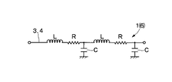
ここで、信号線路3,4にコモンモードの信号が伝搬するときには、信号線路3,4に通電している電流の向きが同方向となる。このとき、信号線路3,4は互いに近接して並設されているから、それぞれの信号線路3,4による磁束が相互に強め合い、コモンモードの信号に対して信号線路3,4が1本の線路のようにふるまう。また、信号線路3,4は磁性体層2b,2cの間に形成されている。このため、コモンモードの信号に対して、信号線路3,4およびグランド電極5によって形成される伝送線路6は、図5の等価回路に示すように、インダクタンスLを持ち、かつ、磁性体層2b,2cの誘電率によりグランド電極5との間に容量Cを持つ。
【0031】
即ち、信号線路3,4は、コモンモードの信号に対しては分布定数回路と等価に機能して、当該信号線路3,4を流れるコモンモードの信号は、インダクタンスL、容量Cが一定に保たれる周波数域においては、損失無く伝送される。一方、コモンモードの信号の周波数が高くなると、磁性体層2b,2cの透磁率が変化し、図6の等価回路のように、インダクタンスLには損失分R(磁性損失)が生じる。このため、磁性損失によって高周波数域のコモンモードの信号は減衰する。
【0032】
これに対し、信号線路3,4にノーマルモードの信号が伝搬するときには、主として信号線路3,4間で、図5の等価回路に示されるような伝送線路6を形成する。このとき、信号線路3,4に通電している電流の向きが逆方向で、かつ通電量がほぼ等しくなる。このため、それぞれの信号線路3,4による磁束は互いに打ち消し合う(相殺する)から、インダクタンスLおよび損失分R(磁性損失)はいずれもコモンモードの場合よりも低減される。
【0033】
しかしながら、均一な媒質中に信号線路3,4を形成した場合、コモンモードとノーマルモードとのいずれのモードであっても実効的な材料特性は変わらない。即ち、どの周波数でも、コモンモード対ノーマルモードの損失の比率は変わらず、信号を通したければノイズ抑制効果が損なわれ、ノイズ抑制効果を高めれば信号が減衰してしまうという不都合がある。
【0034】
これに対し、第1の参考例では、信号線路3,4の間に磁性体層2b,2cの比透磁率μr0よりも小さい比透磁率μr1をもった誘電体部材7を設けたから、ノーマルモードで発生する磁束φnは、図3に示すように誘電体部材7を通過する(横切る)のに対し、コモンモードで発生する磁束φcは、図4に示すように誘電体部材7を通過しない。このため、誘電体部材7を設けた場合と設けない場合とを比較したときには、ノーマルモードで発生する磁束φnの通り道では、誘電体部材7によって実効比透磁率μwnが低下するのに対し、コモンモードで発生する磁束φcの通り道では、実効比透磁率μwcは低下しない。
【0035】
このとき、図7に示すように、一般に実効比透磁率が低下すると、損失のピークが生じる周波数(実効比透磁率に対応した透磁率の実部μ′と虚部μ″が同じ値となる周波数)が高周波側にシフトする傾向がある。このため、誘電体部材7を設けない場合には、例えば図8に示すように、数MHz程度で損失のピークが生じるのに対して、誘電体部材7を設けた場合には、例えば図9に示すように、数十MHz程度で損失のピークが生じる。このとき、透磁率の虚部μ″と実部μ′との比率(μ″/μ′)および実部μ′の大きさによって定まる損失の大きさ自体も、誘電体部材7を設けない場合に比べて誘電体部材7を設けた場合の方が小さくなる。
【0036】
従って、ノーマルモードの信号に対しては、磁性損失Rのピークが生じる周波数が高周波側にシフトすると共に、磁性損失R自体も小さくなる。この結果、コモンモードの信号は低い周波数から除去できるのに対して、ノーマルモードの信号は、高い周波数成分まで減衰せずに伝搬することができる。このため、必要なモードであるノーマルモードの信号を波形なまりが生じることなく伝送することができ、波形品質の維持とノイズ除去効果とを両立させることができる。
【0037】
また、信号線路3,4のそれぞれの幅寸法、磁性体層2b,2cの厚さ寸法(グランド電極5間の距離寸法)を適宜設定することによって、各信号線路3,4の特性インピーダンスを設定することができる。さらに、信号線路3,4間の距離によって、ノーマルモードの特性インピーダンスを設定することができる。ここで、磁性体材料の比誘電率や比透磁率が一定の周波数領域では、これらの特性インピーダンスをほぼ一定値に保持することができる。このため、信号周波数がこの領域にあたるように材料特性を定めることによって、ノイズフィルタ1に接続される回路に対してインピーダンス整合を取ることができ、ノイズフィルタ1の反射損失を低下させ、共振によるノイズの増大や信号波形の乱れを防止することができる。
【0038】
さらに、2層の磁性体層2b、2c間に信号線路3,4を配設すると共に、当該2層の磁性体層2b,2cを2つのグランド電極5によって挟む構成としたから、2つのグランド電極5によって磁性体層2b,2c間に位置する信号線路3,4をその全長に亘って覆うことにより伝送線路6を形成することができる。このため、伝送線路6の全長に亘ってコモンモード特性インピーダンスを一定値に設定できるから、伝送線路6の途中でノイズに反射が生じることがなく、ノイズの共振を抑制することができる。また、2つのグランド電極5によって信号線路3,4をその全長に亘って覆うから、外部からの信号線路3,4中にノイズが混入するのを防ぐことができ、信号を確実に伝達することができる。
【0039】
また、誘電体部材7によって、伝送線路6のノーマルモード特性インピーダンスとコモンモード特性インピーダンスとを個別に設定することができるから、信号側のノーマルモード特性インピーダンスは接続対象となる外部に回路に対して整合を取った状態で、ノイズ側のコモンモード特性インピーダンスは外部の回路に対して整合を外す構成と整合を取る構成のいずれの構成も選択することができる。整合を外した場合には、反射損失を用いてノイズを抑制することができ、整合を取った場合には、反射に伴う共振等の不都合を回避しつつ磁性体層2b,2cの熱損失を用いてノイズを抑制することができる。
【0040】
いずれの場合でも、ノーマルモード特性インピーダンスとは独立してコモンモード特性インピーダンスを設定できるから、反射かつ/または熱損失を利用して従来技術に比べてコモンモード信号に対する伝送損失を大きくすることができる。特に、第1の参考例では、従来技術で見られた高周波域(数100MHz以上)での挿入損失の共振点がないから、10GHz程度までノイズの減衰効果を得ることができる。また、信号線路3,4の幅寸法、磁性体層2b,2cの厚さ寸法、材料特性等を適宜設定することによって、従来技術に比べて、ノーマルモード特性インピーダンスは外部の回路に対して容易に整合させることができ、共振等による信号波形への影響を少なくすることができる。
【0041】
なお、第1の参考例では、コモンモードノイズの周波数が低い場合には、当該コモンモードノイズを透過させる性質を有し、ローパスフィルタのように動作する。つまり、ノイズフィルタ1には、周波数によってコモンモードノイズの通過域と減衰域とがある。この通過域と減衰域は、磁性体層2b,2cの磁性材料の組成(比透磁率)および信号線路3,4の長さ寸法を調整することによって定める。このため、コモンモードノイズの周波数を考慮し、減衰対象のコモンモードノイズを確実に減衰させることができるように磁性体層2b,2cの材料組成、信号線路3,4の長さ寸法が設定されている。
【0042】
かくして、第1の参考例によれば、2層の磁性体層2b,2c間に信号線路3,4を配設すると共に、これらの磁性体層2b,2cを2つのグランド電極5によって覆う構成としたから、磁性体層2b,2cを構成する磁性材料の磁性損失(熱損失)を用いることによってコモンモードノイズを抑制することができる。また、誘電体部材7(異性媒質)を用いて実効比透磁率を下げることにより、実効比透磁率を高い周波数まで一定となるようにしたので、信号線路3,4のノーマルモード特性インピーダンスを広い周波数でほぼ一定値に保持することができるから、外部の回路とのインピーダンス整合を容易に取ることができる。このため、ノイズフィルタ1の反射損失を低下させることができ、共振によるノイズの増大や信号波形の乱れを防止することができる。
【0043】
また、信号線路3,4の間には誘電体部材7を設けたから、コモンモードモードの信号に影響を与えることなく、ノーマルモードの信号に対して実効比透磁率μwnの周波数特性を変化させ、磁性損失Rのピークが生じる周波数が高周波側にシフトさせることができる。このため、コモンモードの信号は低い周波数から除去できるのに対して、ノーマルモードの信号は高い周波数成分まで減衰せずに伝搬することができる。この結果、コモンモードの信号に対するノイズ除去効果を維持しつつ、ノーマルモードの信号に対する波形なまりを防止して波形品質の維持することができる。
【0044】
さらに、2つのグランド電極5によって磁性体層2b,2c間に位置する信号線路3,4をその全長に亘って覆うことができるから、信号線路3,4およびグランド電極5によって形成される伝送線路6の全長に亘ってコモンモード特性インピーダンスを一定値に設定することができ、伝送線路6の途中でノイズが反射することがないのに加え、外部から伝送線路6中にノイズが混入するのを防ぐことができ、信号を確実に伝達することができる。
【0045】
また、誘電体部材7によって、伝送線路6のノーマルモード特性インピーダンスとコモンモード特性インピーダンスとを個別に設定することができるから、信号側のノーマルモード特性インピーダンスは外部に回路に整合を取った状態で、ノイズ側のコモンモード特性インピーダンスは外部の回路に対して整合を外す構成と整合を取る構成とのいずれの構成も選択することができる。そして、いずれの構成を選択した場合でも、反射かつ/または熱損失を利用して従来技術に比べてコモンモード信号に対する伝送損失を大きくすることができる。特に、第1の参考例では、従来技術で見られた高周波域(数100MHz以上)での挿入損失の共振点がないから、10GHz程度までノイズの減衰効果を得ることができる。また、ノーマルモード特性インピーダンスは外部の回路に対して容易に整合させることができ、共振等によるノーマルモード信号波形への影響を少なくすることができる。
【0046】
また、磁性体層2a〜2dは略四角状に形成し、該磁性体層2a〜2dの長さ方向両端側には信号線路3,4の両端に接続された信号用電極端子8,9を設け、該磁性体層2a〜2dの長さ方向中間位置にはグランド電極5に接続されたグランド用電極端子10を設ける構成としたから、直線状に延びる配線の途中に磁性体層2a〜2dの長さ方向両端側に位置する信号用電極端子8,9を容易に接続することができる。また、磁性体層2a〜2dの長さ方向中間位置に設けられたグランド用電極端子10も配線の周辺に設けられたグランド端子に容易に接続することができるから、ノイズフィルタ1の組付け性を向上することができる。
【0047】
さらに、信号線路3,4を蛇行したジグザグ状に形成したから、信号線路3,4の長さ寸法を増加させることができ、ノイズの減衰量を増加させることができる。
【0048】
なお、前記第1の参考例では、信号線路3,4をジグザグ状に形成するものとしたが、図10に示す第2の参考例のように、信号線路3′,4′をコイル状(渦巻き状)に形成してもよい。
【0049】
次に、図11ないし図14は本発明の実施の形態によるノイズフィルタを示し、本実施の形態によるノイズフィルタの特徴は、磁性体層の表面に2本の信号線路を並設し、磁性体層の裏面にグランド電極を設け、2本の信号線路の間には誘電体部材を設けると共に、2本の信号線路を磁性特性を有するコーティング膜によって覆う構成としたことにある。
【0050】
11は本実施の形態によるノイズフィルタで、該ノイズフィルタ11は後述する磁性体層12a,12b、信号線路13,14、グランド電極15、誘電体部材17、コーティング膜18、信号用電極端子19,20、グランド用電極端子21によって大略構成されている。
【0051】
12はノイズフィルタ11の外形を構成する略角柱状の積層体で、該積層体12は、2層の磁性体層12a,12bを焼成することによって形成され、各磁性体層12a,12bは、第1の参考例と同様に例えばフェライト等を用いて略四角形(長方形)の板状に形成されている。
【0052】
13,14は磁性体層12aの表面に配設された2本の信号線路で、該信号線路13,14は、一定の間隔をもって平行に延び、ジグザグ状をなしつつ磁性体層12aの長さ方向に向けて延びている。そして、信号線路13,14は、第1の参考例と同様に導電性金属材料によって略帯状に形成され、後述するグランド電極15によってその裏面側が略全長に亘って覆われることによって伝送線路16を形成している。また、信号線路13,14は、その両端側が電極部13A,14Aとなって後述の信号用電極端子19,20にそれぞれ接続されている。
【0053】
15は磁性体層12aの裏面側(磁性体層12a,12b間)に設けられたグランド電極で、該グランド電極15は、導電性金属材料を用いて略四角形の平板状に形成され、磁性体層12aの裏面側を略全面に亘って覆っている。さらに、グランド電極15のうち略四角状をなす磁性体層12aの長さ方向中間位置には、幅方向両端側に向けて舌状に突出して延びる電極部15Aが設けられ、該電極部15Aは後述のグランド用電極端子21に接続されている。そして、グランド電極15は、磁性体層12aおよび2本の信号線路13,14と一緒に伝送線路16を構成している。
【0054】
17は2本の信号線路13,14の間に設けられた異性媒質としての誘電体部材で、該誘電体部材17は、第1の参考例による誘電体部材7とほぼ同様の材料を用いて形成され、その比透磁率μr1が磁性体層12aの比透磁率μr0よりも小さい値(μr1≒1)に設定されると共に、その比誘電率εr1が磁性体層12aの比誘電率εr0とほぼ同じ値に設定されている。そして、誘電体部材17は、互いに並設された2本の信号線路13,14間の隙間を埋めている。
【0055】
18は積層体12の表面に設けられたコーティング膜で、該コーティング膜18は、例えば樹脂材料に磁粉を混入することによって形成されている。また、コーティング膜18は、例えば磁性体層12aの比透磁率μr0とほぼ同じ値の比透磁率μr2を有し、比透磁率μr2は誘電体部材17の比透磁率μr1よりも高い値に設定されている。そして、コーティング膜18は、誘電体部材17を含めて2本の信号線路13,14を覆っている。
【0056】
19,20は積層体12の四隅側にそれぞれ設けられた信号用電極端子で、該信号用電極端子19,20は、第1の参考例と同様に導電性金属材料等によって略コ字状に形成されると共に、信号線路13,14の電極部13A,14Aにそれぞれ接続されている。
【0057】
21は積層体12の長さ方向中間位置で幅方向の両端側にそれぞれ設けられたグランド用電極端子で、該グランド用電極端子21は、第1の参考例と同様に導電性金属材料等によって略コ字状に形成されると共に、グランド電極15の電極部15Aに接続されている。
【0058】
かくして、本実施の形態では2本の信号線路13,14の間に誘電体部材17を設けると共に、これらの信号線路13,14と誘電体部材17をコーティング膜18によって覆ったから、図13および図14に示すように、ノーマルモードとコモンモードのいずれの場合でも、コーティング膜18と磁性体層12aの内部に磁束φn,φcを閉じ込めることができると共に、コモンモードの実効比透磁率μwcに影響を与えることなく、ノーマルモードの実効比透磁率μwnを低下させることができる。このため、第1の参考例とほぼ同様の作用効果を得ることができる。
【0059】
なお、材料の選定、配線の方法等は実施の形態に示したものに限らず、第1の参考例と同様に種々の変更が可能である。
【0060】
また、前記実施の形態では、信号線路13,14をジクザグ状に形成するものとしたが、第2の参考例のようにコイル状等に形成してもよい。また、本発明は、ジグザグ状、コイル状に限らず、例えば直線状の信号線路を形成してもよい。
【0061】
また、前記実施の形態では、異性媒質として非磁性体媒質からなる誘電体部材17を用いる構成とした。しかし、本発明はこれに限らず、第1の参考例と同様に、異性媒質として低透磁率媒質または空隙を用いてもよい。
【0062】
【発明の効果】
請求項1の発明によれば、磁性体媒質の表面に2本の信号線路を並設し、磁性体媒質の裏面にグランド電極を設けることにより伝送線路を形成したから、磁性体媒質の磁性損失(熱損失)を利用して伝送線路を伝搬する信号を減衰させることができる。また、2本の信号線路の間には異性媒質を配設したから、該異性媒質によって各モード毎に実効的な材料特性を変化させることができる。この結果、各モード毎に信号の減衰量を調整することができ、必要なノーマルモードの信号の損失を小さくでき、または不要なコモンモードの信号の損失を大きくすることができる。さらに、グランド電極によって2本の信号線路を絶縁性媒質の裏面側から全長に亘って覆うことができるから、各伝送線路の全長に亘ってコモンモード特性インピーダンスを一定値に設定でき、伝送線路の途中でノイズの反射、共振が生じるのを抑制することができる。
【0063】
また、2本の信号線路の間に設けた異性媒質によって、伝送線路のノーマルモード特性インピーダンスとコモンモード特性インピーダンスとを個別に設定することができるから、ノーマルモード特性インピーダンスは外部に回路に対して整合させた状態で、コモンモード特性インピーダンスは外部の回路に対して整合を外す構成と整合を取る構成とのいずれの構成も選択できると共に、いずれの場合でも、反射かつ/または熱損失を利用して従来技術に比べてコモンモード信号に対する伝送損失を大きくすることができる。特に、本発明の構成では、従来技術で見られた高周波域(数100MHz以上)での挿入損失の共振点がないから、10GHz程度までノイズの減衰効果を得ることができる。また、ノーマルモード特性インピーダンスは外部の回路に対して容易に整合させることができ、共振等によるノーマルモード信号波形への影響を少なくすることができる。
【0064】
さらに、2本の信号線路の間には、磁性体媒質よりも比透磁率が小さい低透磁率媒質、非磁性体媒質または空隙からなる異性媒質を配置するから、2つのモードのうちノーマルモードの磁束だけが通過する位置に異性媒質を配置することができる。このため、2つのモードのうちノーマルモードに対する実効比透磁率を低下させることができ、ノーマルモードの信号を波形なまりが生じることなく伝達することできる。
【0065】
また、異質媒質よりも比透磁率が高いコーティング膜によって該異性媒質および2本の信号線路を覆う構成としたから、磁性体媒質およびコーティング膜の磁性損失(熱損失)を用いて信号を減衰させることができる。
【0066】
請求項2,3の発明によれば、信号線路をジグザグ状またはコイル状に形成したから、信号線路を直線状に形成した場合に比べて、その長さ寸法を増加させることができ、不要なコモンモードの信号(ノイズ)に対する減衰量を増加させることができる。
【図面の簡単な説明】
【図1】 第1の参考例によるノイズフィルタを示す斜視図である。
【図2】 第1の参考例によるノイズフィルタを分解して示す分解斜視図である。
【図3】 ノーマルモードの信号が伝搬している状態でノイズフィルタを図1中の矢示III−III方向からみた断面図である。
【図4】 コモンモードの信号が伝搬している状態でノイズフィルタを示す図3と同様な位置の断面図である。
【図5】 コモンモードの信号に対する伝送線路の等価回路を示す回路図である。
【図6】 高周波のコモンモードの信号に対する伝送線路の等価回路を示す回路図である。
【図7】 周波数に対する透磁率の実部と虚部を示す特性線図である。
【図8】 誘電体部材を設けない場合の周波数に対する透磁率の実部と虚部を示す特性線図である。
【図9】 誘電体部材を設けた場合の周波数に対する透磁率の実部と虚部を示す特性線図である。
【図10】 第2の参考例によるノイズフィルタを分解して示す分解斜視図である。
【図11】 本発明の実施の形態によるノイズフィルタを示す斜視図である。
【図12】 図11中のノイズフィルタを分解して示す分解斜視図である。
【図13】 ノーマルモードの信号が伝搬している状態でノイズフィルタを図11中の矢示XIII−XIII方向からみた断面図である。
【図14】 コモンモードの信号が伝搬している状態でノイズフィルタを示す図13と同様な位置の断面図である。
【符号の説明】
1,11 ノイズフィルタ
2,12 積層体(絶縁性媒質)
2a〜2d,12a,12b 磁性体層(絶縁層)
3,4,13,14 信号線路
5,15 グランド電極
6,16,6′ 伝送線路
7,17,7′ 誘電体部材(非磁性体媒質)[0001]
BACKGROUND OF THE INVENTION
The present invention relates to a noise filter suitable for use in an electronic circuit using a differential signal such as a high-speed differential interface.
[0002]
[Prior art]
In general, an electronic circuit using a differential signal (normal mode signal) is constituted by a differential line composed of two lines. Then, common mode noise (common mode signal) that causes radiation of electromagnetic noise flows through the differential line due to various causes. For this reason, a common mode choke coil as a noise filter is connected in the middle of the differential line to allow the normal mode signal to pass therethrough, but the common mode noise is removed by reflecting the common mode signal.
[0003]
[Problems to be solved by the invention]
By the way, in the above-described prior art, noise is suppressed by reflection loss. For example, when a noise filter is disposed in a line connecting circuits, a specific frequency is set between the noise filter and peripheral circuits. There was a problem that noise sometimes resonated and the noise was amplified instead.
[0004]
In particular, in recent years, there is a tendency that the signal frequency used for the digital device is increased, and the number of electronic devices whose signal frequency exceeds 100 MHz is increasing. For this reason, while common mode noise and the like have high frequencies, for example, the line length between the noise filter and the surrounding components, the line length between multiple components, etc. cannot be ignored for high frequency noise. It has become. For this reason, the noise filter according to the prior art tends not to sufficiently remove noise or distort the signal waveform due to the influence of the resonance frequency due to reflection. Therefore, a noise filter using reflection loss as in the prior art tends to be difficult to use for electronic devices using high-frequency signals.
[0005]
For example, when a noise filter is configured using a chip coil in which two lines are embedded in a medium such as ferrite, the two lines are provided in a uniform medium. If the ratio of attenuation to the signal of one mode among the normal mode is determined, the ratio of attenuation (transmission) to the signal of the other mode is also determined, and the attenuation ratio of the signal is individually set in each mode Tended to be difficult.
[0006]
The present invention has been made in view of the above-described problems of the prior art, and an object of the present invention is to provide a small noise filter capable of preventing noise resonance and setting a signal attenuation ratio for each mode. Is to provide.
[0007]
[Means for Solving the Problems]
In order to solve the above-described problem, the invention of
[0008]
As a result, the two signal lines are layered.Magnetic materialBecause it is provided on the surface of the medium,Magnetic materialMediumMagnetic loss (Heat loss)Can be used to attenuate signals propagating through the transmission line. Also,Between the two signal lines, a low-permeability medium, a non-magnetic medium, or a gap having a relative permeability smaller than that of the magnetic mediumSince the isomeric medium is arranged, effective material characteristics for each mode by the isomeric medium(Frequency characteristic)Can be changed. As a result, the signal attenuation can be adjusted for each mode,normalMode signal loss can be reduced or unnecessarycommonThe loss of mode signals can be increased. Furthermore, since the transmission line can be formed by covering the two signal lines from the back side of the insulating medium over the entire length with the ground electrode, the common mode characteristic impedance is made constant over the entire length of the transmission line. It can be set, and noise reflection and resonance can be suppressed in the middle of the transmission line.
[0009]
Also,Between two signal linesThe normal mode characteristic impedance and the common mode characteristic impedance of the transmission line can be set individually by the heterogeneous medium installed in the signal line, so that the normal mode characteristic impedance on the signal side is matched to the external circuit. The common mode characteristic impedance on the noise side can be selected from either a configuration in which matching is removed from an external circuit or a configuration in which matching is performed. Regardless of which configuration is selected, the common mode characteristic impedance can be set independently of the normal mode characteristic impedance. Therefore, the transmission loss for the common mode signal is increased compared to the prior art by using reflection and / or heat loss. can do. In particular, in the configuration according to the present invention, since there is no resonance point of insertion loss in the high frequency range (several hundred MHz or more) found in the prior art, a noise attenuation effect can be obtained up to about 10 GHz. Compared with the prior art, the normal mode characteristic impedance can be easily matched to an external circuit, and the influence on the signal waveform due to resonance or the like can be reduced.
[0010]
AlsoSince the two signal lines are arranged in parallel with each other, a magnetic flux surrounding the two signal lines as a whole is formed in the common mode, whereas the two signal lines are respectively connected in the normal mode. Independently surrounding magnetic flux is formed. For this reason, no magnetic flux is formed between the two signal lines in the common mode, whereas a magnetic flux (magnetic field) is formed across the two signal lines in the normal mode. Therefore, by arranging the isomeric medium between the two signal lines, only the normal mode magnetic flux can be adjusted.
[0011]
Also, since the two signal lines are arranged in parallel with each other, an electric flux (electric field) is formed between the two signal lines and, for example, the ground electrode in the common mode, whereas in the normal mode, Sometimes an electric flux is formed connecting the two signal lines. Therefore, by arranging the isomeric medium between the two signal lines, only the normal mode electric flux can be adjusted.
[0012]
Further, since the isomeric medium and the two signal lines are covered with a coating film having a relative permeability higher than that of the isomeric medium,The signal can be attenuated by using the magnetic loss (heat loss) of the magnetic medium and the coating film. In addition, since a low permeability medium having a relative permeability smaller than that of the magnetic medium is disposed between the two signal lines, the frequency characteristic of the effective relative permeability for the normal mode of the two modes is changed. The frequency at which the loss peak occurs in the normal mode, which is a necessary mode, can be shifted to the high frequency side. Therefore, the common mode signal can be removed from the low frequency, while the normal mode signal can pass through the high frequency component without being attenuated, and the normal mode signal does not cause waveform rounding. Can communicate.
[0013]
Claim2In the invention, the signal line is formed in a meandering zigzag shape,3In the invention, the signal line is formed in a coil shape. As a result, the length of the signal line can be increased as compared with the case where the signal line is formed in a straight line, and the amount of attenuation with respect to an unnecessary mode signal (noise) can be increased.
[0014]
DETAILED DESCRIPTION OF THE INVENTION
Hereinafter, a noise filter according to an embodiment of the present invention will be described in detail with reference to the accompanying drawings.
[0015]
First,1 to 9 areOf the present inventionFirstReference example1First reference
[0016]
[0017]
It is not always necessary to use a magnetic material for the
[0018]
For the
[0019]
[0020]
In addition, the
[0021]
[0022]
[0023]
3 and 4, the thickness of the isomeric medium (dielectric member 7) is substantially the same as the thickness of the
[0024]
Moreover, instead of the
[0025]
The material of the insulating medium or the isomeric medium is selected depending on the purpose of use of the filter and the convenience of the manufacturing process. That is, when an insulating medium is selected, for example, a composite material in which scaly pure iron powder is dispersed in a resin, Mn-Zi ferrite, Ni-Zn ferrite, hexagonal, in order from the lowest noise suppression target frequency A material such as crystal ferrite is selected. On the other hand, when an isomeric medium is selected, it is desirable in terms of characteristics to set the relative permeability μr1 of the isomeric medium to 1 (μr1 = 1). However, considering for example damage due to a difference in thermal expansion coefficient during firing, it is better that the isomeric medium has a smaller difference in material properties from the insulating medium. For example, as a combination of the isomeric medium and the insulating medium, glass In addition to selecting a combination of ferrite and ferrite, it is also conceivable to select a combination of low permeability ferrite and high permeability ferrite.
[0026]
8 and 9 are signal electrode terminals provided on the four corner sides of the laminate 2 (
[0027]
[0028]
First reference
[0029]
First, the
[0030]
Here, when a common mode signal propagates through the
[0031]
That is, the
[0032]
On the other hand, when a normal mode signal propagates through the
[0033]
However, when the
[0034]
In contrast,First reference exampleSince the
[0035]
At this time, as shown in FIG. 7, when the effective relative permeability generally decreases, the frequency at which a loss peak occurs (the real part μ ′ and the imaginary part μ ″ of the magnetic permeability corresponding to the effective relative permeability have the same value). Therefore, when the
[0036]
Therefore, for a normal mode signal, the frequency at which the peak of the magnetic loss R occurs shifts to the high frequency side, and the magnetic loss R itself decreases. As a result, the common mode signal can be removed from the low frequency, whereas the normal mode signal can propagate to the high frequency component without being attenuated. For this reason, a signal in a normal mode, which is a necessary mode, can be transmitted without causing waveform rounding, and both maintenance of waveform quality and a noise removal effect can be achieved.
[0037]
Further, the characteristic impedance of each
[0038]
Further, since the
[0039]
Moreover, since the normal mode characteristic impedance and the common mode characteristic impedance of the
[0040]
In any case, since the common mode characteristic impedance can be set independently of the normal mode characteristic impedance, the transmission loss for the common mode signal can be increased compared to the conventional technique by using reflection and / or heat loss. . In particular,First reference exampleThen, since there is no resonance point of insertion loss in the high frequency range (several hundred MHz or more) found in the prior art, it is possible to obtain a noise attenuation effect up to about 10 GHz. Further, by appropriately setting the width dimensions of the
[0041]
In addition,First reference exampleThen, when the frequency of the common mode noise is low, it has a property of transmitting the common mode noise and operates like a low-pass filter. In other words, the
[0042]
Thus,First reference exampleSince the
[0043]
In addition, since the
[0044]
Further, since the
[0045]
Further, the normal mode characteristic impedance and the common mode characteristic impedance of the
[0046]
The
[0047]
Further, since the
[0048]
The firstReference exampleIn FIG. 10, the
[0049]
Next, FIGS. 11 to 14 show the present invention.The fruitThe noise filter according to the embodiment is shown. The noise filter according to the present embodiment is characterized in that two signal lines are arranged in parallel on the surface of the magnetic layer, and a ground electrode is provided on the back surface of the magnetic layer. A dielectric member is provided between the signal lines, and the two signal lines are covered with a coating film having magnetic properties.
[0050]
11 is a noise filter according to the present embodiment. The
[0051]
12 is a substantially prismatic laminate constituting the outer shape of the
[0052]
[0053]
[0054]
[0055]
[0056]
19 and 20 are signal electrode terminals provided on the four corner sides of the laminate 12, respectively. The
[0057]
21 are ground electrode terminals provided at both ends in the width direction at intermediate positions in the longitudinal direction of the
[0058]
Thus, in this embodimentIsSince the
[0059]
In addition, material selection, wiring method, etc.Is realNot limited to those shown in the embodiment, the firstReference exampleVarious modifications are possible as well.
[0060]
Also beforeRealIn the embodiment, the
[0061]
Also beforeRealIn the embodiment, the
[0062]
【The invention's effect】
Claim1According to the invention ofMagnetic materialTwo signal lines are juxtaposed on the surface of the medium,Magnetic materialBecause the transmission line was formed by providing a ground electrode on the back of the medium,Magnetic materialMediumMagnetic loss (Heat loss)Can be used to attenuate signals propagating through the transmission line. Also,Between the two signal linesSince an isomeric medium is provided, effective material characteristics can be changed for each mode by the isomeric medium. As a result, the signal attenuation can be adjusted for each mode,normalMode signal loss can be reduced or unnecessarycommonThe loss of mode signals can be increased. Furthermore, since the two signal lines can be covered over the entire length from the back side of the insulating medium by the ground electrode, the common mode characteristic impedance can be set to a constant value over the entire length of each transmission line. It is possible to suppress noise reflection and resonance during the process.
[0063]
Also,Between two signal linesThe normal mode characteristic impedance and the common mode characteristic impedance of the transmission line can be set individually by the heterogeneous medium installed in the The impedance can be selected from either a configuration that removes the matching to the external circuit or a configuration that matches, and in either case, a common mode signal is used in comparison with the prior art using reflection and / or heat loss. The transmission loss with respect to can be increased. In particular, in the configuration of the present invention, since there is no resonance point of insertion loss in the high frequency range (several hundred MHz or more) found in the prior art, a noise attenuation effect can be obtained up to about 10 GHz. Further, the normal mode characteristic impedance can be easily matched to an external circuit, and the influence on the normal mode signal waveform due to resonance or the like can be reduced.
[0064]
furtherBetween the two signal lines, a low-permeability medium, a non-magnetic medium, or a gap having a relative permeability smaller than that of the magnetic medium.Isometric medium consisting ofFrom placeThe isomeric medium can be arranged at a position where only the normal mode magnetic flux passes through the two modes. For this reason,The effective relative permeability with respect to the normal mode of the two modes can be reduced, and the signal of the normal mode can be transmitted without causing waveform rounding.
[0065]
Heterogeneous mediaThe coating film having a higher relative permeability thanOpposite sexmediumand2 signal linesThe roadSince it is configured to cover, the signal can be attenuated by using the magnetic loss (heat loss) of the magnetic medium and the coating film..
[0066]
Claim2,3According to the invention, since the signal line is formed in a zigzag shape or a coil shape, the length of the signal line can be increased as compared with the case where the signal line is formed in a straight line.commonThe amount of attenuation with respect to the mode signal (noise) can be increased.
[Brief description of the drawings]
FIG. 1 FirstReference exampleIt is a perspective view which shows the noise filter by.
FIG. 2 FirstReference exampleIt is a disassembled perspective view which decomposes | disassembles and shows the noise filter by.
3 is a cross-sectional view of the noise filter as viewed from the direction of arrows III-III in FIG. 1 in a state where a normal mode signal is propagated.
4 is a cross-sectional view of the same position as in FIG. 3 showing the noise filter in a state in which a common mode signal is propagated.
FIG. 5 is a circuit diagram showing an equivalent circuit of a transmission line for a common mode signal.
FIG. 6 is a circuit diagram showing an equivalent circuit of a transmission line for a high-frequency common mode signal.
FIG. 7 is a characteristic diagram showing a real part and an imaginary part of magnetic permeability with respect to frequency.
FIG. 8 is a characteristic diagram showing a real part and an imaginary part of magnetic permeability with respect to frequency when no dielectric member is provided.
FIG. 9 is a characteristic diagram showing a real part and an imaginary part of a magnetic permeability with respect to a frequency when a dielectric member is provided.
FIG. 102ofreferenceIt is a disassembled perspective view which decomposes | disassembles and shows the noise filter by an example.
FIG. 11The present inventionIt is a perspective view which shows the noise filter by embodiment of this.
FIG.In FIG.It is a disassembled perspective view which decomposes | disassembles and shows a noise filter.
13 is a cross-sectional view of the noise filter viewed from the direction of arrows XIII-XIII in FIG. 11 in a state in which a normal mode signal is propagated.
14 is a cross-sectional view of the same position as FIG. 13 showing the noise filter in a state in which a common mode signal is propagated..
[Explanation of symbols]
1,11Noise filter
2,12Laminate (insulating medium)
2a to 2d, 12a, 12bMagnetic layer (insulating layer)
3,4,13,14Signal line
5,15Ground electrode
6, 16, 6 'Transmission line
7, 17, 7′ Dielectric material (non-magnetic material medium)
Claims (3)
前記2本の信号線路の間には、前記磁性体媒質よりも比透磁率が小さい低透磁率媒質、非磁性体媒質または空隙からなる異性媒質を配設し、
該異性媒質よりも比透磁率が高いコーティング膜によって該異性媒質と前記2本の信号線路とを覆う構成としたことを特徴とするノイズフィルタ。Consists of a magnetic medium made of a layered insulating magnetic material, two signal lines arranged side by side on the surface of the magnetic medium, and a ground electrode provided on the back surface of the magnetic medium. A noise filter that removes unnecessary common mode signals from a common mode in which signals in the same direction propagate through the two signal lines and a normal mode in which signals in different directions propagate through the two signal lines. And
Between the front SL two signal lines, the magnetic low permeability medium relative permeability is less than the medium, the isomeric medium made of a nonmagnetic material medium or voids disposed,
A noise filter characterized in that the isomeric medium and the two signal lines are covered with a coating film having a relative permeability higher than that of the isomeric medium.
Priority Applications (5)
| Application Number | Priority Date | Filing Date | Title |
|---|---|---|---|
| JP2003201298A JP4370838B2 (en) | 2002-08-21 | 2003-07-24 | Noise filter |
| CNB031548482A CN1259673C (en) | 2002-08-21 | 2003-08-20 | Noise filter |
| US10/644,780 US6853268B2 (en) | 2002-08-21 | 2003-08-21 | Noise filter |
| KR1020030057961A KR100568506B1 (en) | 2002-08-21 | 2003-08-21 | Noise filter |
| EP03255174A EP1432136A3 (en) | 2002-08-21 | 2003-08-21 | Noise filter |
Applications Claiming Priority (2)
| Application Number | Priority Date | Filing Date | Title |
|---|---|---|---|
| JP2002240906 | 2002-08-21 | ||
| JP2003201298A JP4370838B2 (en) | 2002-08-21 | 2003-07-24 | Noise filter |
Publications (2)
| Publication Number | Publication Date |
|---|---|
| JP2004140788A JP2004140788A (en) | 2004-05-13 |
| JP4370838B2 true JP4370838B2 (en) | 2009-11-25 |
Family
ID=32072432
Family Applications (1)
| Application Number | Title | Priority Date | Filing Date |
|---|---|---|---|
| JP2003201298A Expired - Fee Related JP4370838B2 (en) | 2002-08-21 | 2003-07-24 | Noise filter |
Country Status (5)
| Country | Link |
|---|---|
| US (1) | US6853268B2 (en) |
| EP (1) | EP1432136A3 (en) |
| JP (1) | JP4370838B2 (en) |
| KR (1) | KR100568506B1 (en) |
| CN (1) | CN1259673C (en) |
Families Citing this family (30)
| Publication number | Priority date | Publication date | Assignee | Title |
|---|---|---|---|---|
| KR100635699B1 (en) * | 2002-07-31 | 2006-10-17 | 엔이씨 도낀 가부시끼가이샤 | Transmission line type noise filter with reduced heat generation even when large dc current flows therein |
| US6956444B2 (en) * | 2003-02-14 | 2005-10-18 | Intel Corporation | Method and apparatus for rejecting common mode signals on a printed circuit board and method for making same |
| JP2004343084A (en) * | 2003-04-21 | 2004-12-02 | Murata Mfg Co Ltd | Electronic component |
| JP2006179596A (en) * | 2004-12-21 | 2006-07-06 | Mitsubishi Electric Corp | Semiconductor device |
| JP2006332302A (en) * | 2005-05-26 | 2006-12-07 | Murata Mfg Co Ltd | Common mode choke coil mounted substrate and common mode choke coil mounting method |
| KR100723531B1 (en) * | 2006-06-13 | 2007-05-30 | 삼성전자주식회사 | Substrates for semiconductor package |
| JP5045058B2 (en) * | 2006-10-25 | 2012-10-10 | パナソニック株式会社 | π-type filter |
| US7538653B2 (en) * | 2007-03-30 | 2009-05-26 | Intel Corporation | Grounding of magnetic cores |
| DE102008019127B4 (en) * | 2008-04-16 | 2010-12-09 | Epcos Ag | Multilayer component |
| DE102008035102A1 (en) * | 2008-07-28 | 2010-02-11 | Epcos Ag | Multilayer component |
| WO2010106840A1 (en) * | 2009-03-18 | 2010-09-23 | 株式会社村田製作所 | Electronic component |
| CN102791181B (en) * | 2010-07-30 | 2014-12-31 | 奥林巴斯医疗株式会社 | Endoscope system |
| KR200454349Y1 (en) * | 2011-01-12 | 2011-06-29 | (주)우리조경건설 | Pagora Column with Wood Finish |
| CN102790599B (en) * | 2012-07-30 | 2015-09-09 | 华为技术有限公司 | Filter |
| JP5660258B2 (en) * | 2012-08-24 | 2015-01-28 | 株式会社村田製作所 | High frequency device and directional coupler |
| US9570222B2 (en) | 2013-05-28 | 2017-02-14 | Tdk Corporation | Vector inductor having multiple mutually coupled metalization layers providing high quality factor |
| US9324490B2 (en) | 2013-05-28 | 2016-04-26 | Tdk Corporation | Apparatus and methods for vector inductors |
| KR101983151B1 (en) * | 2013-10-15 | 2019-05-28 | 삼성전기주식회사 | common mode filter |
| JP6254071B2 (en) * | 2013-11-26 | 2017-12-27 | サムソン エレクトロ−メカニックス カンパニーリミテッド. | Common mode filter and electronic device provided with common mode filter |
| KR101973412B1 (en) * | 2013-12-31 | 2019-09-02 | 삼성전기주식회사 | Common mode filter |
| CN104966601A (en) * | 2014-03-26 | 2015-10-07 | 莱尔德电子材料(深圳)有限公司 | Nonmagnetic ferrite dielectric for common mode choke |
| US9735752B2 (en) | 2014-12-03 | 2017-08-15 | Tdk Corporation | Apparatus and methods for tunable filters |
| JP6414529B2 (en) | 2015-09-25 | 2018-10-31 | 株式会社村田製作所 | Electronic components |
| JP6565555B2 (en) * | 2015-09-30 | 2019-08-28 | Tdk株式会社 | Multilayer common mode filter |
| KR101735599B1 (en) * | 2015-11-11 | 2017-05-16 | 주식회사 모다이노칩 | Circuit protection device |
| JP6614109B2 (en) * | 2016-11-21 | 2019-12-04 | 株式会社村田製作所 | Electronic equipment with wireless circuit |
| JP6845540B2 (en) * | 2017-05-17 | 2021-03-17 | 国立大学法人信州大学 | Single layer thin film common mode filter |
| JP6696483B2 (en) * | 2017-07-10 | 2020-05-20 | 株式会社村田製作所 | Coil parts |
| KR102105385B1 (en) * | 2018-07-18 | 2020-04-28 | 삼성전기주식회사 | Coil component |
| CN112909455B (en) * | 2019-11-19 | 2022-04-05 | 英业达科技有限公司 | Noise suppression filter and method for manufacturing noise suppression filter |
Family Cites Families (7)
| Publication number | Priority date | Publication date | Assignee | Title |
|---|---|---|---|---|
| FR2077965B1 (en) * | 1970-02-27 | 1973-11-16 | Anvar | |
| JP2959787B2 (en) * | 1990-01-20 | 1999-10-06 | 毅 池田 | Laminated LC noise filter and manufacturing method thereof |
| WO1991017944A1 (en) | 1990-05-18 | 1991-11-28 | The Dow Chemical Company | Polyolefin laminate cling films |
| RU2139613C1 (en) * | 1993-08-27 | 1999-10-10 | Мурата Мануфакчуринг Ко., Лтд. | Thin-film multilayer electrode coupled by high-frequency electromagnetic field, high-frequency transmission line, high-frequency resonator, high-frequency filter, high- frequency band-pass rejection filter and high-frequency device |
| JP3252605B2 (en) * | 1994-07-04 | 2002-02-04 | 株式会社村田製作所 | Electronic component and method of manufacturing the same |
| US6806794B2 (en) * | 2000-08-12 | 2004-10-19 | Murata Manufacturing Co., Ltd. | Noise filter |
| WO2002056322A1 (en) | 2001-01-15 | 2002-07-18 | Matsushita Electric Industrial Co., Ltd. | Noise filter and electronic apparatus comprising this noise filter |
-
2003
- 2003-07-24 JP JP2003201298A patent/JP4370838B2/en not_active Expired - Fee Related
- 2003-08-20 CN CNB031548482A patent/CN1259673C/en not_active Expired - Fee Related
- 2003-08-21 KR KR1020030057961A patent/KR100568506B1/en not_active IP Right Cessation
- 2003-08-21 EP EP03255174A patent/EP1432136A3/en not_active Withdrawn
- 2003-08-21 US US10/644,780 patent/US6853268B2/en not_active Expired - Lifetime
Also Published As
| Publication number | Publication date |
|---|---|
| CN1485863A (en) | 2004-03-31 |
| JP2004140788A (en) | 2004-05-13 |
| US20040070468A1 (en) | 2004-04-15 |
| EP1432136A3 (en) | 2005-03-16 |
| US6853268B2 (en) | 2005-02-08 |
| EP1432136A2 (en) | 2004-06-23 |
| CN1259673C (en) | 2006-06-14 |
| KR20040018188A (en) | 2004-03-02 |
| KR100568506B1 (en) | 2006-04-07 |
Similar Documents
| Publication | Publication Date | Title |
|---|---|---|
| JP4370838B2 (en) | Noise filter | |
| US7616085B2 (en) | Common mode choke coil | |
| US20060028303A1 (en) | Noise filter | |
| WO2011013543A1 (en) | Common mode filter | |
| JP2010177380A (en) | Common mode filter and mounting structure thereof | |
| JPH07193403A (en) | Resonator | |
| US8373072B2 (en) | Printed circuit board | |
| WO2003001665A1 (en) | Noise filter | |
| US6806794B2 (en) | Noise filter | |
| US5300903A (en) | Band-pass filter | |
| JP2007281315A (en) | Coil component | |
| US10707546B2 (en) | Dielectric filter unit comprising three or more dielectric blocks and a transmission line for providing electromagnetically coupling among the dielectric resonators | |
| JP4788065B2 (en) | Multilayer transmission line crossing chip | |
| US6417460B1 (en) | Multi-layer circuit board having signal, ground and power layers | |
| JP3863674B2 (en) | Common mode filter | |
| JP2004048090A (en) | Noise filter | |
| JP2000252124A (en) | Common mode filter | |
| JP2005347379A (en) | Common mode filter | |
| JPH088499A (en) | Printed circuit board structure of distributed constant circuit | |
| JP4415530B2 (en) | Connection structure of differential line and noise filter | |
| JPH1197962A (en) | High-frequency component | |
| KR102542708B1 (en) | Circuit board, inductor, and radio apparatus | |
| JPS59200516A (en) | Filter | |
| JP2006223005A (en) | High frequency transmission line and electronic component having it | |
| JPH11220409A (en) | Antenna composite component |
Legal Events
| Date | Code | Title | Description |
|---|---|---|---|
| A621 | Written request for application examination |
Free format text: JAPANESE INTERMEDIATE CODE: A621 Effective date: 20050513 |
|
| A131 | Notification of reasons for refusal |
Free format text: JAPANESE INTERMEDIATE CODE: A131 Effective date: 20080212 |
|
| A521 | Written amendment |
Free format text: JAPANESE INTERMEDIATE CODE: A523 Effective date: 20080411 |
|
| A131 | Notification of reasons for refusal |
Free format text: JAPANESE INTERMEDIATE CODE: A131 Effective date: 20090428 |
|
| A521 | Written amendment |
Free format text: JAPANESE INTERMEDIATE CODE: A523 Effective date: 20090619 |
|
| TRDD | Decision of grant or rejection written | ||
| A01 | Written decision to grant a patent or to grant a registration (utility model) |
Free format text: JAPANESE INTERMEDIATE CODE: A01 Effective date: 20090811 |
|
| A01 | Written decision to grant a patent or to grant a registration (utility model) |
Free format text: JAPANESE INTERMEDIATE CODE: A01 |
|
| A61 | First payment of annual fees (during grant procedure) |
Free format text: JAPANESE INTERMEDIATE CODE: A61 Effective date: 20090824 |
|
| FPAY | Renewal fee payment (event date is renewal date of database) |
Free format text: PAYMENT UNTIL: 20120911 Year of fee payment: 3 |
|
| R150 | Certificate of patent or registration of utility model |
Ref document number: 4370838 Country of ref document: JP Free format text: JAPANESE INTERMEDIATE CODE: R150 Free format text: JAPANESE INTERMEDIATE CODE: R150 |
|
| FPAY | Renewal fee payment (event date is renewal date of database) |
Free format text: PAYMENT UNTIL: 20120911 Year of fee payment: 3 |
|
| FPAY | Renewal fee payment (event date is renewal date of database) |
Free format text: PAYMENT UNTIL: 20130911 Year of fee payment: 4 |
|
| LAPS | Cancellation because of no payment of annual fees |