JP4366239B2 - Charged particle beam equipment - Google Patents
Charged particle beam equipment Download PDFInfo
- Publication number
- JP4366239B2 JP4366239B2 JP2004136972A JP2004136972A JP4366239B2 JP 4366239 B2 JP4366239 B2 JP 4366239B2 JP 2004136972 A JP2004136972 A JP 2004136972A JP 2004136972 A JP2004136972 A JP 2004136972A JP 4366239 B2 JP4366239 B2 JP 4366239B2
- Authority
- JP
- Japan
- Prior art keywords
- sample
- gas
- probe
- charged particle
- supply unit
- Prior art date
- Legal status (The legal status is an assumption and is not a legal conclusion. Google has not performed a legal analysis and makes no representation as to the accuracy of the status listed.)
- Expired - Fee Related
Links
Images


Description
本発明は、荷電粒子線を用いての試料表面にガスを供給し、ビーム誘起堆積膜の形成や、エッチング作用による加工速度増大などの機能を有し、試料の任意の位置にプローブを接触させる機能を有する荷電粒子線装置に関する。 The present invention supplies a gas to the surface of a sample using a charged particle beam, has functions such as formation of a beam-induced deposition film and an increase in processing speed by an etching action, and a probe is brought into contact with an arbitrary position of the sample. The present invention relates to a charged particle beam device having a function.
例えば集束イオンビーム装置(以下FIB)において、試料の表面にガスを供給し、ガスが照射している領域内の部分をイオンビームで照射すると、ガス種によってはビーム誘起堆積(以下ガスアシストデポジション(GAD))膜が形成したり、エッチング作用が増大し加工速度が大きくなる(以下ガスアシストエッチング(GAE))ことが知られている。 For example, in a focused ion beam apparatus (hereinafter referred to as FIB), when a gas is supplied to the surface of a sample and a portion within a region irradiated with the gas is irradiated with an ion beam, beam induced deposition (hereinafter referred to as gas assisted deposition) is performed depending on the type of gas. (GAD)) It is known that a film is formed, an etching action is increased, and a processing speed is increased (hereinafter referred to as gas assist etching (GAE)).
また、GAD膜により、プローブと試料を接続して試料の一部を分離する方法が特許文献1に記載されている。該方法によればプローブを試料の任意の位置に接触させた後、ガス雰囲気中でのイオンビーム照射により形成したGAD膜によりプローブと試料を接続して、試料室内で試料の一部を分離することが可能である。 Patent Document 1 describes a method of separating a part of a sample by connecting the probe and the sample with a GAD film. According to this method, after a probe is brought into contact with an arbitrary position of a sample, the probe and the sample are connected by a GAD film formed by ion beam irradiation in a gas atmosphere, and a part of the sample is separated in the sample chamber. It is possible.
ガスを試料の表面に照射するためには、ガスの放出口を試料の近傍に配置する必要がある。ガス供給部の位置調整の方法は特許文献2に示されているものがある。この方法によると、ガス供給部の位置合わせは、放出口の先端部にビームをフォーカスさせて、得られた画像、例えば走査イオン顕微鏡像(以下SIM像)を観察しながら行っている。ガス供給部の調整手順として、一度、試料表面にフォーカスするように対物レンズに印加する電圧を調整し、次に試料表面から数100μm上方(イオン源側)にフォーカス位置がくるように対物レンズのフォーカス電圧を調整する。次に、対物レンズのフォーカス電圧値を保持しながら、ガス供給部の先端部にフォーカスが合うようにガス供給部の位置調整を行う場合が多い。この方法では、フォーカス電圧を確認して、ガス供給部を動かしてフォーカスが合うよう位置決めをするなど手順が煩雑であり、ユーザによる位置合わせ精度にはばらつきがある。このため、位置が多少ずれた場合でも試料上にガスが充分に行き渡るようにガス流量を計算値よりも多めに供給する必要があり、ガス源の補充頻度の増大や排ガスによる環境に与える負荷の増大につながっていた。さらに、試料交換の度にガス放出口の位置の確認を行う必要があり、作業性が悪い。
In order to irradiate the surface of the sample with the gas, it is necessary to dispose the gas outlet near the sample. A method for adjusting the position of the gas supply unit is disclosed in
また、特許文献1に示す試料分離方法では、プローブを試料に接触させるために、プローブ自体を移動させて位置合わせをした後、ガスを供給する機構を試料表面近傍へと移動させるといった手順を踏む。この方法では、プローブとガス供給部の両方を調整する必要があるため、試料を分離するための加工時間を短縮する場合の阻害要因となっている。また、プローブとガス供給部が極近傍に配置されるため、分離した試料取り出す際にプローブとガス供給部が接触する可能性があり、試料を破損・紛失してしまうといった問題も生じる。 Moreover, in the sample separation method shown in Patent Document 1, in order to bring the probe into contact with the sample, the probe itself is moved and aligned, and then the mechanism for supplying the gas is moved to the vicinity of the sample surface. . In this method, since it is necessary to adjust both the probe and the gas supply unit, this is an obstacle to shortening the processing time for separating the sample. In addition, since the probe and the gas supply unit are disposed in the immediate vicinity, there is a possibility that the probe and the gas supply unit may come into contact with each other when a separated sample is taken out, which causes a problem that the sample is damaged or lost.
上記問題を解決するため、ガス供給部とプローブとの位置関係を一定に保ち、プローブを利用してガス供給部の位置合わせを行うこととした。プローブの位置合わせは、プローブの先端部が試料に接触した場合の帯電状態や電気抵抗の変化等をモニターすることで容易に行うことができる。本発明の第一の構成として、ガス供給部とプローブの移動手段を、両者の位置関係が一定に保たれる様に制御することとした。本発明の第二の構成として、ガス供給部を移動させる手段とプローブを移動させる手段の少なくとも一部を共通とすることとした。またはプローブとガス供給部の複合体を備えることとした。 In order to solve the above problem, the positional relationship between the gas supply unit and the probe is kept constant, and the gas supply unit is aligned using the probe. The alignment of the probe can be easily performed by monitoring the charged state and the change in electrical resistance when the tip of the probe contacts the sample. As a first configuration of the present invention, the gas supply unit and the probe moving means are controlled so that the positional relationship between them is kept constant. As a second configuration of the present invention, at least a part of the means for moving the gas supply unit and the means for moving the probe are made common. Alternatively, a composite of a probe and a gas supply unit is provided.
上記第一,第二の構成によれば、プローブを用いてガス供給部の位置合わせを行うことができるので、ガス供給部の位置合わせ精度が向上する。これにより供給部が常に最適な位置に配置されるのでガス流量を計算値に近い値に設定でき、ガス源の補充頻度を減らし、排ガスによる環境に与える負荷も減らすことができる。また、プローブの位置を合わせればガス供給部の位置合わせを個別に行う必要がなく、作業時間を短縮することができる。さらに、ガス供給部とプローブが接触するのを防ぐことができる。また、上記第二の構成によれば、プローブの可動範囲が広がるという効果も得られる。 According to the first and second configurations, since the gas supply unit can be aligned using the probe, the alignment accuracy of the gas supply unit is improved. As a result, the supply unit is always arranged at an optimal position, so that the gas flow rate can be set to a value close to the calculated value, the gas source replenishment frequency can be reduced, and the load on the environment caused by the exhaust gas can also be reduced. Further, if the position of the probe is aligned, it is not necessary to individually align the gas supply unit, and the working time can be shortened. Furthermore, it is possible to prevent the gas supply unit and the probe from contacting each other. Moreover, according to said 2nd structure, the effect that the movable range of a probe spreads is also acquired.
以下に、本発明の実施例について図面を用いて説明する。図1に第一の実施例として
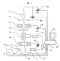
FIB装置の概略構成図を示す。液体金属イオン源11から引き出し電極12により引き出されたGaイオンビームは加速電圧Voで加速され、集束レンズ13,ビーム制限絞り14,偏向器15,対物レンズ16などからなるイオン光学系で集束,偏向されて、試料3上を走査する。この時、ビームの照射により試料表面から発生した二次信号は、二次信号検出器19によって検出し、アンプ20により増幅され、偏向制御と同期させる事によりデータ処理部21の画像表示装置22上にSIM像として表示される。試料3はステージ30の上に搭載され、少なくともX,Y,Z方向に移動可能なステージ30を移動させる事により試料3上の任意の位置を観察・加工する事ができる。加速電圧Vo,各レンズ(この場合は集束レンズ13,対物レンズ16)の電圧,ビーム制限絞り14などの条件はデータ処理部21に記憶され、それぞれの条件に応じて加速電圧Voの高電圧電源23,引き出し電圧Vextの高電圧電源24,集束レンズ13の高電圧電源25,対物レンズ16の高電圧電源27を制御する処理部21で、加工領域の設定,加工・観察に用いる一連のビーム条件を自動で設定できる。
Embodiments of the present invention will be described below with reference to the drawings. FIG. 1 shows a schematic configuration diagram of an FIB apparatus as a first embodiment. The Ga ion beam extracted from the liquid
ここで、ガス供給部の制御部29とプローブの制御部31により、ガス供給部とプローブの位置関係が一定に保たれるように制御する。具体的には、例えばプローブをX方向に1mm移動すると、自動的にガス供給部も同様に移動する。プローブ6とガス供給部5の位置は、以下の2条件を満たすようにするとよい。
条件1:プローブ6先端付近にてガス供給部5からの放出ガスの濃度分布の中心部がくるように位置調整する。
条件2:プローブ6が試料3表面に達する前にガス供給部5が試料3に接触しないように、プローブ6先端部はガス供給部5の最下部よりも試料3側に配置する。
Here, the
Condition 1: The position is adjusted so that the central portion of the concentration distribution of the gas released from the
Condition 2: The tip of the
上記条件を満足した場合、プローブ6先端部が試料3に接触したとき、プローブ6の先端部付近では供給されるガスの密度はGAD,GAEに適した状態になっている。従来行われていた、対物レンズ16によるフォーカス位置調整を用いたガス供給部5とプローブ6の位置合わせは不要になり、作業性の向上が達成される。また、プローブ6の先端部付近にて供給されるガスの濃度分布の中心部がくるようになったので、ガス流量を従来よりも減らして計算値に近づけた場合でもGAD,GAEの条件が満たされるようになった。これにより、ガスの節約につながり、ガス源の補充頻度を減らし、排ガスによる環境への負荷も低減できる。
When the above conditions are satisfied, when the tip of the
プローブ6と試料3が接触したか否かを判断するには、プローブ6先端部が試料3に接触あるいはごく近傍に近づいた場合、プローブ6から試料3の帯電が逃げることによる、試料3表面の帯電状態の変化をモニターすればよい。この状態のときには試料3においてプローブ6付近の帯電を抑えることができ、絶縁物試料の場合でもイオンビーム照射にて発生するチャージアップによる障害のないGAD,GAE加工が可能になる。帯電が変化した場合はSIM像のコントラストの変化となって現れるため、プローブの接触・非接触が容易に判定できる。また、このコントラストの変化は目視により確認することも可能であるが、プローブ6を接触させる前の画像を画像記憶部32に記憶させておき、プローブ6が近づくか、接触したことによってコントラストが変化した画像とを前期記憶した画像と比較することで、プローブ6位置の検出が可能である。
In order to determine whether or not the
また、プローブ6先端の電気抵抗を測定し、プローブ6と試料3とが接触したことで、抵抗値がある一定の値以下になったことでもプローブの接触・非接触が容易に判定できる。
Further, the electrical resistance at the tip of the
プローブ6が試料3に近づくか、接触した場合に装置上のランプもしくは音、あるいは画面上に表示・通知することもできる。また、プローブ6が試料3に近づくか、あるいは接触したことを検知した場合、その位置でプローブおよびガス供給部の動作を止めればよい。このようにプローブの位置合わせを行えば、プローブの動きに連動してガス供給部の位置もあわせることができる。また、プローブとガス供給部が接触することがない。
When the
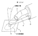
続いて第二の実施例を図2(a),図2(b)に示す。図2(b)は、図2(a)において試料近傍を拡大した図である。本実施例は、第一の実施例とはプローブ,ガス供給部の構成が異なっており、プローブとガス供給部の移動手段の少なくとも一部が共通となっている。プローブとガス供給部の位置関係は第一の実施例で示した条件1,2を満たすようにし、プローブの試料への接触・非接触を検出することでプローブの位置を合わせ、それに伴ってガス供給部も移動する。このことによりガス供給部の位置合わせ精度が向上するとともに、プローブとガス供給部が接触することがない。試料の分離加工を行う場合、図2(b)に示すようにプローブ6を分離したい試料3の表面に接触させて、そのプローブ6と試料3の接触部を含む領域、例えば加工領域10にガスを吹きつけながらFIB加工を行う。するとGAD膜によりプローブ6が試料3と接着し、試料3から切り離す加工へと移行することができる。
Next, a second embodiment is shown in FIGS. 2 (a) and 2 (b). FIG. 2B is an enlarged view of the vicinity of the sample in FIG. This embodiment is different from the first embodiment in the configuration of the probe and the gas supply unit, and at least a part of the moving means of the probe and the gas supply unit is common. The positional relationship between the probe and the gas supply unit satisfies the
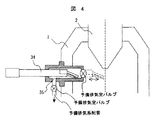
図2(a)においてFIBカラム2は図1で示した光学系の構成を略した形で示す。真空容器である試料室1にFIBカラム2が搭載され、試料3がX,Y,Z方向に駆動可能な試料ステージ(図示せず)上に搭載されて、試料室1内に供給され加工および観察を行う。ガス供給部5とプローブ6は共通の移動手段4に搭載され(ガス供給部5とプローブ6の複合体をユニット34とする)試料室1内に供給される。また、プローブ6とガス供給部5との間は、熱伝導の低い物質(例えばポリイミド樹脂)で構成された熱絶縁部8にて熱絶縁することにより、加熱して使用するガス源を用いた場合でも他部へ熱の影響を与えることなく使用できる。例えばプローブ先端部の熱膨張によるドリフトを避けることができる。ガス源の貯蔵部および加熱部39はユニット34のガス供給部5の近くに配置している。ガス源の貯蔵部および加熱部39を一体化し、ガス放出口の近くに配置することは、試料室内(真空内)に配置することになり、大気中に配置するよりも保温性に優れるため、少ない加熱量においてガス源の固体化によるガス供給部の配管詰まりを防止することができる。また、加熱部位は装置使用者の手に触れない位置にあるので、使用者の安全を確保することができる。ここではガスを加熱して使用する場合について述べたが、ガスを加熱して使用しない場合は、ガス加熱部を備えていなくても良い。
In FIG. 2A, the
また、プローブ6の交換等により、プローブ6とガス供給部5との位置合わせの微調整を行うことがあるため、プローブ6のみ独立して移動できるように図2(b)に示すようなプローブ位置調整手段37を設けてもよい。その場合、データ処理部21に、移動手段4の初期状態の座標値として、プローブ6とガス供給部5の前記位置条件1,2を満たし、プローブがSIM像の中心部にある場合の座標値を記録しておく。プローブ6交換後、データ処理部21から読み出した移動手段4の初期状態の座標値に移動し、次にプローブ位置調整手段37で、プローブ6先端位置がSIM像の中心になるように移動させてもよい。
Further, since the positioning of the
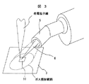
続いて第三の実施例における試料近傍のガス供給部5とプローブ6の構成を図3に示す。本実施例では、ガス供給口からプローブ6が出ている構成となっており、ガスはプローブの周りから供給される。この構成の場合、プローブ6の先端部分にて常に充分な量のガスを供給することが出来るので、プローブ6のみ独立して移動できるような手段を設ける必要がない。また、試料近傍にさらにスペースが生まれ、例えば別のプローブやガス供給系などを配置することができる。
Next, the configuration of the
第二,第三の実施例においてユニット34を試料室1に供給する際、予備排気系35を経由してもよい。この構成を第二の実施例を例に図4に示す。予備排気系35があることで、試料室1全体を大気に開放することなく、ユニット34のみを試料室1から切り離すことが可能になる。これによって、ユニット34全体やプローブ6やガス供給部5などのメンテナンスや、プローブ6の交換,ガス源の交換が容易になる。さらに、試料室1から出し入れ可能であることで、使用しない場合は、荷電粒子線ビームから遠ざけておくことが出来るため、試料3の観察や加工の妨げにならない。
When the
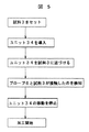
前述した一連の動作を図5のフローチャートに示す。試料3を試料室1内に供給し、次にユニット34を供給する。ユニット34を移動制御部33にて制御される移動手段4でもって試料3に近づけていき、接触したことをデータ処理部21に存在する接触検知部
36が検知すると、ユニット34の移動制御部33は移動するのを止める。その位置で加工・処理を開始する。このフローをすべて自動化することで、加工を含む自動化が可能になる。
The series of operations described above is shown in the flowchart of FIG.
また、第二,第三の実施例で示したようにプローブとガス供給部の移動手段の一部を一体とすることで、プローブの可動範囲を広げることができる。図6(a),(b)に試料分離加工を行った後の試料付近の拡大図を示す。分離した試料51は例えば透過電子顕微鏡(以下、TEM)の試料としてメッシュ52の上面に取り付けられる。分離した試料
51がメッシュ52に接触した状態でGAD加工を行い、分離した試料51とメッシュ
52をGADによる体積膜で固定する。固定後、プローブ6の分離した試料51との接続部をFIBにより切断する。その後、TEMの電子ビームを側方より照射して分離した試料の観察を行う。
In addition, as shown in the second and third embodiments, the probe and the moving means of the gas supply unit are integrated, so that the movable range of the probe can be expanded. 6 (a) and 6 (b) show enlarged views of the vicinity of the sample after the sample separation processing. The separated
分離した試料51をメッシュ52に取り付けるときの平面図を図6(b)に示す。従来はガス供給部5がプローブ6と別の駆動系を用いていたため、プローブ6と別の方向から供給している。また、試料の傾斜方向との関係上、ガス供給部5をプローブ6とメッシュ乗せ台に対して反対側から供給するとステージを傾斜した場合にメッシュ乗せ台53と干渉するため、ガス供給部5はプローブ6と同じ側からしか供給することはできない。このため、図6(b)において破線で示したように、ガス供給部5とプローブ6が別々の移動手段で制御されている場合、メッシュ上に分離した試料51を取り付け範囲は、ガス供給部5がプローブ6と干渉しない範囲、すなわち取り付け範囲54に示すようにメッシュ
52の一部分のみとなっていた。このため、従来の取り付け範囲54は長さが500μm程度であり、分離した試料51を1つのメッシュに5,6検体しか取り付けることが出来なかった。
A plan view when the separated
本発明により、図6(b)において実線で示したようにプローブ6とガス供給部5を少なくとも一部が共通の移動手段にて動作させることで同方向からの供給ができるようになった。このため、分離した試料51を取り付け範囲は55に示すように従来の範囲より大幅に拡がった。今回の例では取り付け範囲の長さは1200μm程度となり、分離した試料51を15〜20検体まで取り付けることが可能となった。本実施例の活用により、メッシュ52の交換頻度が減り、TEM観察用の試料の作成効率を上げることができた。
According to the present invention, as shown by the solid line in FIG. 6B, at least a part of the
1…試料室、2…FIBカラム、3,28…試料、4…移動手段、5…ガス供給部、6…プローブ、8…熱絶縁部、9…GAD加工領域、10…GAD加工領域(プローブ接着加工時)、11…液体金属イオン源、12…引き出し電極、13…集束レンズ、14…ビーム制限絞り、15…偏向器、16…対物レンズ、19…二次信号検出器、20…アンプ、21…データ処理部、22…画像表示装置、23…加速電圧の高電圧電源、24…引き出し電圧の高電圧電源、25…集束レンズの高電圧電源、26…偏向信号発生器、27…対物レンズの高電圧電源、29…ガス供給部の制御部、30…ステージ、31…プローブの制御部、32…画像記憶部、33…移動手段制御部、34…ユニット、35…予備排気系、36…接触検知部、37…プローブ位置調整手段、39…ガス源の貯蔵部および加熱部、51…分離した試料、52…メッシュ、53…メッシュ乗せ台、54…取り付け範囲、55…本発明での取り付け範囲。
DESCRIPTION OF SYMBOLS 1 ... Sample chamber, 2 ... FIB column, 3,28 ... Sample, 4 ... Moving means, 5 ... Gas supply part, 6 ... Probe, 8 ... Thermal insulation part, 9 ... GAD processing area, 10 ... GAD processing area (probe) 11 ... liquid metal ion source, 12 ... extraction electrode, 13 ... focusing lens, 14 ... beam limiting aperture, 15 ... deflector, 16 ... objective lens, 19 ... secondary signal detector, 20 ... amplifier, DESCRIPTION OF
Claims (15)
前記ガス供給部移動手段と、前記プローブ移動手段の移動手段の少なくとも一部が共通であり、前記ガス供給部と前記プローブを少なくとも一部が共通の移動手段にて動作させ、
前記プローブ先端部が試料に接触したとき、前記プローブ先端部付近にて前記ガス供給部からの放出ガスの濃度分布の中心部がくるように前記ガス供給部が位置調整され、当該プローブ先端部付近では、供給される前記ガスアシストデポジション用のガスの濃度がガスアシストデポジションに適した状態となることを特徴とする荷電粒子線装置。 Charged particle source, electromagnetic or electrostatic lens, deflector for scanning charged particle beam, sample drive mechanism that can move by loading sample, and detection of secondary signal generated by charged particle irradiation from sample Means for forming and displaying the detected secondary signal as an image, a gas supply unit for supplying a gas for gas assist deposition to the sample, means for moving the gas supply unit, and gas assist deposition In a charged particle beam apparatus comprising a probe connected to a sample by a film and means for moving the probe,
The gas supply unit moving unit and at least a part of the moving unit of the probe moving unit are common, and the gas supply unit and the probe are operated by at least a part of the common moving unit,
When the probe tip comes into contact with the sample, the position of the gas supply unit is adjusted so that the center of the concentration distribution of the gas released from the gas supply unit is near the probe tip, and the vicinity of the probe tip Then, the charged particle beam apparatus is characterized in that the concentration of the supplied gas for gas assist deposition is in a state suitable for gas assist deposition.
前記ガス供給部は、前記プローブと一定の位置関係を保つよう制御され、
前記プローブ先端部が試料に接触したとき、前記プローブ先端部付近にて前記ガス供給部からの放出ガスの濃度分布の中心部がくるように前記ガス供給部が位置調整され、当該プローブ先端部付近では、供給される前記ガスアシストデポジション用のガスの濃度がガスアシストデポジションに適した状態となることを特徴とする荷電粒子線装置。 A charged particle source, an electromagnetic or electrostatic lens, a deflector for scanning a charged particle beam, a sample driving means that can be moved by mounting a sample, and a secondary signal generated by irradiation of charged particles from the sample is detected. Means for forming and displaying the detected secondary signal as an image, a gas supply part for supplying a gas for gas assist deposition to the sample surface, and a probe connected to the sample by a gas assist deposition film In a charged particle beam apparatus comprising:
The gas supply unit is controlled to maintain a certain positional relationship with the probe,
When the probe tip comes into contact with the sample, the position of the gas supply unit is adjusted so that the center of the concentration distribution of the gas released from the gas supply unit is near the probe tip, and the vicinity of the probe tip Then, the charged particle beam apparatus is characterized in that the concentration of the supplied gas for gas assist deposition is in a state suitable for gas assist deposition.
前記ガス供給部と前記プローブは複合体を形成し、前記プローブ先端部が試料に接触したとき、前記プローブ先端部付近にて前記ガス供給部からの放出ガスの濃度分布の中心部がくるように前記ガス供給部が位置調整され、当該プローブ先端部付近では、供給される前記ガスアシストデポジション用のガスの濃度がガスアシストデポジションに適した状態となることを特徴とする荷電粒子線装置。 A charged particle source, an electromagnetic or electrostatic lens, a deflector for scanning a charged particle beam, a sample driving means that can be moved by mounting a sample, and a secondary signal generated by irradiation of charged particles from the sample is detected. Means for forming and displaying the detected secondary signal as an image, a gas supply part for supplying a gas for gas assist deposition to the sample surface, and a probe connected to the sample by a gas assist deposition film In a charged particle beam apparatus comprising:
The gas supply unit and the probe form a complex, and when the probe tip comes into contact with the sample, the concentration distribution of the emitted gas from the gas supply unit is located near the probe tip. The charged particle beam apparatus according to claim 1, wherein the gas supply unit is adjusted in position, and a concentration of the supplied gas assist deposition gas is suitable for gas assist deposition near the tip of the probe.
Priority Applications (1)
| Application Number | Priority Date | Filing Date | Title |
|---|---|---|---|
| JP2004136972A JP4366239B2 (en) | 2004-05-06 | 2004-05-06 | Charged particle beam equipment |
Applications Claiming Priority (1)
| Application Number | Priority Date | Filing Date | Title |
|---|---|---|---|
| JP2004136972A JP4366239B2 (en) | 2004-05-06 | 2004-05-06 | Charged particle beam equipment |
Publications (2)
| Publication Number | Publication Date |
|---|---|
| JP2005322419A JP2005322419A (en) | 2005-11-17 |
| JP4366239B2 true JP4366239B2 (en) | 2009-11-18 |
Family
ID=35469541
Family Applications (1)
| Application Number | Title | Priority Date | Filing Date |
|---|---|---|---|
| JP2004136972A Expired - Fee Related JP4366239B2 (en) | 2004-05-06 | 2004-05-06 | Charged particle beam equipment |
Country Status (1)
| Country | Link |
|---|---|
| JP (1) | JP4366239B2 (en) |
Families Citing this family (3)
| Publication number | Priority date | Publication date | Assignee | Title |
|---|---|---|---|---|
| JP2009115677A (en) | 2007-11-08 | 2009-05-28 | Jeol Ltd | Sample preparation method and system |
| KR102358551B1 (en) * | 2014-08-29 | 2022-02-04 | 가부시키가이샤 히다치 하이테크 사이언스 | Automatic sample strip manufacturing apparatus |
| US12308207B2 (en) * | 2022-08-18 | 2025-05-20 | Applied Materials Israel Ltd. | Enhanced deposition rate by thermal isolation cover for GIS manipulator |
-
2004
- 2004-05-06 JP JP2004136972A patent/JP4366239B2/en not_active Expired - Fee Related
Also Published As
| Publication number | Publication date |
|---|---|
| JP2005322419A (en) | 2005-11-17 |
Similar Documents
| Publication | Publication Date | Title |
|---|---|---|
| JP5227643B2 (en) | An electron beam application device that enables observation with high resolution and high contrast | |
| JP4408538B2 (en) | Probe device | |
| US6794663B2 (en) | Method and apparatus for specimen fabrication | |
| US7683319B2 (en) | Charge control apparatus and measurement apparatus equipped with the charge control apparatus | |
| US7582885B2 (en) | Charged particle beam apparatus | |
| US7696496B2 (en) | Apparatus for ion beam fabrication | |
| JP2001273861A (en) | Charged beam device and pattern tilt observation method | |
| US10692688B2 (en) | Charged particle beam apparatus | |
| KR20010040911A (en) | Focused particle beam systems and methods using a tilt column | |
| KR102559888B1 (en) | Charged particle beam apparatus | |
| US20130087703A1 (en) | Electron microscope | |
| JP2010055756A (en) | Method of irradiating charged corpuscular particle beam, and charged corpuscular particle beam apparatus | |
| JP2002148159A (en) | Sample preparation method and sample preparation device | |
| CN104251795A (en) | Plan view sample preparation | |
| JP2021093336A (en) | Image adjustment method and electric charge particle beam system | |
| JP4366239B2 (en) | Charged particle beam equipment | |
| JP2015038477A (en) | Detaching probe from tem sample during sample preparation | |
| US20060249692A1 (en) | Composite charged particle beam apparatus and an irradiation alignment method in it | |
| JP4520905B2 (en) | Analysis device, probe control method, and analysis system | |
| JP4719554B2 (en) | Focused ion beam device | |
| JP2009004126A (en) | Charged particle beam processing equipment | |
| JP5544439B2 (en) | Charged particle beam equipment | |
| JP2012230919A (en) | Method of irradiation of charged particle beam, and charged particle beam apparatus | |
| JPH10241588A (en) | Focused ion beam processing method and apparatus | |
| US20140291509A1 (en) | Charged particle beam apparatus and method for forming observation image |
Legal Events
| Date | Code | Title | Description |
|---|---|---|---|
| RD04 | Notification of resignation of power of attorney |
Free format text: JAPANESE INTERMEDIATE CODE: A7424 Effective date: 20060509 |
|
| A621 | Written request for application examination |
Free format text: JAPANESE INTERMEDIATE CODE: A621 Effective date: 20060630 |
|
| A521 | Request for written amendment filed |
Free format text: JAPANESE INTERMEDIATE CODE: A523 Effective date: 20060630 |
|
| A977 | Report on retrieval |
Free format text: JAPANESE INTERMEDIATE CODE: A971007 Effective date: 20090128 |
|
| A131 | Notification of reasons for refusal |
Free format text: JAPANESE INTERMEDIATE CODE: A131 Effective date: 20090210 |
|
| A521 | Request for written amendment filed |
Free format text: JAPANESE INTERMEDIATE CODE: A523 Effective date: 20090413 |
|
| A131 | Notification of reasons for refusal |
Free format text: JAPANESE INTERMEDIATE CODE: A131 Effective date: 20090512 |
|
| A521 | Request for written amendment filed |
Free format text: JAPANESE INTERMEDIATE CODE: A523 Effective date: 20090626 |
|
| TRDD | Decision of grant or rejection written | ||
| A01 | Written decision to grant a patent or to grant a registration (utility model) |
Free format text: JAPANESE INTERMEDIATE CODE: A01 Effective date: 20090804 |
|
| A01 | Written decision to grant a patent or to grant a registration (utility model) |
Free format text: JAPANESE INTERMEDIATE CODE: A01 |
|
| A61 | First payment of annual fees (during grant procedure) |
Free format text: JAPANESE INTERMEDIATE CODE: A61 Effective date: 20090824 |
|
| FPAY | Renewal fee payment (event date is renewal date of database) |
Free format text: PAYMENT UNTIL: 20120828 Year of fee payment: 3 |
|
| R150 | Certificate of patent or registration of utility model |
Free format text: JAPANESE INTERMEDIATE CODE: R150 |
|
| FPAY | Renewal fee payment (event date is renewal date of database) |
Free format text: PAYMENT UNTIL: 20130828 Year of fee payment: 4 |
|
| LAPS | Cancellation because of no payment of annual fees |