JP4366178B2 - Turbine airfoil section with long and short chord lengths and high and low temperature performance - Google Patents
Turbine airfoil section with long and short chord lengths and high and low temperature performance Download PDFInfo
- Publication number
- JP4366178B2 JP4366178B2 JP2003396596A JP2003396596A JP4366178B2 JP 4366178 B2 JP4366178 B2 JP 4366178B2 JP 2003396596 A JP2003396596 A JP 2003396596A JP 2003396596 A JP2003396596 A JP 2003396596A JP 4366178 B2 JP4366178 B2 JP 4366178B2
- Authority
- JP
- Japan
- Prior art keywords
- airfoils
- airfoil
- turbine
- row
- stage
- Prior art date
- Legal status (The legal status is an assumption and is not a legal conclusion. Google has not performed a legal analysis and makes no representation as to the accuracy of the status listed.)
- Expired - Fee Related
Links
Images


Classifications
-
- F—MECHANICAL ENGINEERING; LIGHTING; HEATING; WEAPONS; BLASTING
- F01—MACHINES OR ENGINES IN GENERAL; ENGINE PLANTS IN GENERAL; STEAM ENGINES
- F01D—NON-POSITIVE DISPLACEMENT MACHINES OR ENGINES, e.g. STEAM TURBINES
- F01D5/00—Blades; Blade-carrying members; Heating, heat-insulating, cooling or antivibration means on the blades or the members
- F01D5/12—Blades
- F01D5/14—Form or construction
- F01D5/141—Shape, i.e. outer, aerodynamic form
- F01D5/142—Shape, i.e. outer, aerodynamic form of the blades of successive rotor or stator blade-rows
-
- F—MECHANICAL ENGINEERING; LIGHTING; HEATING; WEAPONS; BLASTING
- F01—MACHINES OR ENGINES IN GENERAL; ENGINE PLANTS IN GENERAL; STEAM ENGINES
- F01D—NON-POSITIVE DISPLACEMENT MACHINES OR ENGINES, e.g. STEAM TURBINES
- F01D5/00—Blades; Blade-carrying members; Heating, heat-insulating, cooling or antivibration means on the blades or the members
- F01D5/12—Blades
- F01D5/14—Form or construction
- F01D5/141—Shape, i.e. outer, aerodynamic form
-
- F—MECHANICAL ENGINEERING; LIGHTING; HEATING; WEAPONS; BLASTING
- F01—MACHINES OR ENGINES IN GENERAL; ENGINE PLANTS IN GENERAL; STEAM ENGINES
- F01D—NON-POSITIVE DISPLACEMENT MACHINES OR ENGINES, e.g. STEAM TURBINES
- F01D9/00—Stators
- F01D9/02—Nozzles; Nozzle boxes; Stator blades; Guide conduits, e.g. individual nozzles
- F01D9/04—Nozzles; Nozzle boxes; Stator blades; Guide conduits, e.g. individual nozzles forming ring or sector
- F01D9/041—Nozzles; Nozzle boxes; Stator blades; Guide conduits, e.g. individual nozzles forming ring or sector using blades
-
- F—MECHANICAL ENGINEERING; LIGHTING; HEATING; WEAPONS; BLASTING
- F05—INDEXING SCHEMES RELATING TO ENGINES OR PUMPS IN VARIOUS SUBCLASSES OF CLASSES F01-F04
- F05D—INDEXING SCHEME FOR ASPECTS RELATING TO NON-POSITIVE-DISPLACEMENT MACHINES OR ENGINES, GAS-TURBINES OR JET-PROPULSION PLANTS
- F05D2240/00—Components
- F05D2240/10—Stators
- F05D2240/12—Fluid guiding means, e.g. vanes
-
- F—MECHANICAL ENGINEERING; LIGHTING; HEATING; WEAPONS; BLASTING
- F05—INDEXING SCHEMES RELATING TO ENGINES OR PUMPS IN VARIOUS SUBCLASSES OF CLASSES F01-F04
- F05D—INDEXING SCHEME FOR ASPECTS RELATING TO NON-POSITIVE-DISPLACEMENT MACHINES OR ENGINES, GAS-TURBINES OR JET-PROPULSION PLANTS
- F05D2250/00—Geometry
- F05D2250/30—Arrangement of components
- F05D2250/34—Arrangement of components translated
-
- F—MECHANICAL ENGINEERING; LIGHTING; HEATING; WEAPONS; BLASTING
- F05—INDEXING SCHEMES RELATING TO ENGINES OR PUMPS IN VARIOUS SUBCLASSES OF CLASSES F01-F04
- F05D—INDEXING SCHEME FOR ASPECTS RELATING TO NON-POSITIVE-DISPLACEMENT MACHINES OR ENGINES, GAS-TURBINES OR JET-PROPULSION PLANTS
- F05D2250/00—Geometry
- F05D2250/70—Shape
-
- F—MECHANICAL ENGINEERING; LIGHTING; HEATING; WEAPONS; BLASTING
- F05—INDEXING SCHEMES RELATING TO ENGINES OR PUMPS IN VARIOUS SUBCLASSES OF CLASSES F01-F04
- F05D—INDEXING SCHEME FOR ASPECTS RELATING TO NON-POSITIVE-DISPLACEMENT MACHINES OR ENGINES, GAS-TURBINES OR JET-PROPULSION PLANTS
- F05D2260/00—Function
- F05D2260/20—Heat transfer, e.g. cooling
- F05D2260/202—Heat transfer, e.g. cooling by film cooling
-
- Y—GENERAL TAGGING OF NEW TECHNOLOGICAL DEVELOPMENTS; GENERAL TAGGING OF CROSS-SECTIONAL TECHNOLOGIES SPANNING OVER SEVERAL SECTIONS OF THE IPC; TECHNICAL SUBJECTS COVERED BY FORMER USPC CROSS-REFERENCE ART COLLECTIONS [XRACs] AND DIGESTS
- Y02—TECHNOLOGIES OR APPLICATIONS FOR MITIGATION OR ADAPTATION AGAINST CLIMATE CHANGE
- Y02T—CLIMATE CHANGE MITIGATION TECHNOLOGIES RELATED TO TRANSPORTATION
- Y02T50/00—Aeronautics or air transport
- Y02T50/60—Efficient propulsion technologies, e.g. for aircraft
Landscapes
- Engineering & Computer Science (AREA)
- Mechanical Engineering (AREA)
- General Engineering & Computer Science (AREA)
- Physics & Mathematics (AREA)
- Fluid Mechanics (AREA)
- Turbine Rotor Nozzle Sealing (AREA)
Description
本発明は、一般的にガスタービンエンジンに関し、より具体的には、ガスタービンエンジンのタービンに関する。 The present invention relates generally to gas turbine engines, and more specifically to a turbine of a gas turbine engine.
ガスタービンエンジンでは、空気が、圧縮機内で加圧されかつ燃焼器内で燃料と混合されて、高温の燃焼ガスを発生し、この高温燃焼ガスが複数のタービン段を通して下流に流れる。タービン段は、ステータベーンを有する固定タービンノズルを含み、該ステータベーンが、支持ディスクから半径方向外向きに延びるタービンロータブレードの下流列を通して燃焼ガスを導き、該支持ディスクがガスからの抽出エネルギーにより駆動される。 In a gas turbine engine, air is pressurized in a compressor and mixed with fuel in a combustor to generate hot combustion gases that flow downstream through a plurality of turbine stages. The turbine stage includes a stationary turbine nozzle having a stator vane that directs combustion gas through a downstream row of turbine rotor blades extending radially outward from the support disk, the support disk being driven by extracted energy from the gas. Driven.
第1段タービンノズルすなわち高圧タービンノズルが、最初に燃焼器から最も高温の燃焼ガスを受け、この燃焼ガスが第1段ロータブレードに導かれ、該第1段ロータブレードが燃焼ガスからエネルギーを取り出す。第2段タービンノズルが、第1段ブレードのすぐ下流に配置されており、次いで燃焼ガスから付加的なエネルギーを取り出す第2段タービンロータブレード列が続く。 A first stage or high pressure turbine nozzle first receives the hottest combustion gas from the combustor, which is directed to the first stage rotor blade, which extracts energy from the combustion gas. . A second stage turbine nozzle is located immediately downstream of the first stage blade, followed by a second stage turbine rotor blade row that extracts additional energy from the combustion gases.
燃焼ガスからエネルギーが取り出されると、燃焼ガスの温度は、対応して低下する。しかしながら、ガス温度は比較的に高いので、高圧タービン段は一般的に、圧縮機から抽気された冷却空気を中空のベーン及びブレード翼形部を通して流すことにより冷却されるか、及び/又は高い高温性能及び高い耐熱性の材料で作られる。タービン材料の高温性能が高ければ高いほど、タービン翼形部は高価になる。 As energy is extracted from the combustion gas, the temperature of the combustion gas is correspondingly reduced. However, because the gas temperature is relatively high, the high pressure turbine stage is typically cooled by flowing cooling air extracted from the compressor through the hollow vanes and blade airfoils and / or high high temperatures. Made of material with high performance and high heat resistance. The higher the high temperature performance of the turbine material, the more expensive the turbine airfoil.
冷却空気は燃焼器から他へ流されるので、エンジンの全体効率は、それに応じて低下する。従って、そのような冷却空気の使用を最少にしてエンジンの全体効率を最大にし、かつより低い耐熱特性を有するタービン材料を用いることにより翼形部の費用を低下させることが非常に望ましい。 As cooling air flows from the combustor to the other, the overall efficiency of the engine decreases accordingly. Accordingly, it is highly desirable to minimize the use of such cooling air to maximize the overall efficiency of the engine and to reduce the cost of the airfoil by using a turbine material having lower heat resistance characteristics.
必要とされる冷却空気の量は、燃焼ガスの温度に左右される。その温度は、エンジンのアイドル運転からその最高出力運転まで変化する。燃焼ガス温度はベーン及びブレードが受ける最大応力に直接影響するので、タービン段の冷却空気所要量は、エンジンの最大燃焼ガス温度での運転に耐えるのに有効なものでなければならないが、そのような運転状態は、エンジン運転時の比較的に短い時間の間に起こる。 The amount of cooling air required depends on the temperature of the combustion gas. The temperature varies from idle operation of the engine to its maximum output operation. Because the combustion gas temperature directly affects the maximum stress experienced by the vanes and blades, the turbine stage cooling air requirement must be effective to withstand the engine's operation at the maximum combustion gas temperature. An unusual operating condition occurs during a relatively short time during engine operation.
例えば、乗客又は貨物を運ぶために飛行中の航空機に動力を供給する民間航空機用のガスタービンエンジンでは、航空機の離陸の間にその最も高温の運転状況が生じる。軍用の航空機用のエンジン用途においては、最も高温の運転状況は、軍事作戦行動に左右されるが、一般的にアフターバーナの作動を伴う離陸の間に起こる。また、発電機に動力を供給する地上設置式ガスタービンエンジンにおいては、最も高温の運転状態は一般的に、暑い日中のピーク電力状態の間に起こる。 For example, in a commercial aircraft gas turbine engine that powers a flying aircraft to carry passengers or cargo, its hottest operating conditions occur during aircraft takeoff. In military aircraft engine applications, the hottest operating conditions depend on military operational behavior, but generally occur during take-off with afterburner operation. Also, in ground-mounted gas turbine engines that power generators, the hottest operating conditions typically occur during hot daytime peak power conditions.
従って、最大燃焼ガス温度は、エンジンの作動又は運転条件にわたって時間と共に変化する。最大燃焼ガス温度はまた、ガスが燃焼器の出口環状空間から吐出される時に、円周方向及び半径方向の両方向で空間的に変化する。この空間的な温度変化は一般的に、燃焼器パターン及び従来から知られているプロファイル係数で表わされる。最も高い温度環境は、燃焼器からの高温ストリークがステータベーンすなわちノズル及び回転ブレードにおける上流翼形部列内に温度変化を生じさせるようなガス流の部分において起こる。上流ウェーク及び高温ストリークにより引き起こされる不安定さにより、翼形部が高温であり、正圧側面が負圧側面より高温になり、かつ流路の中間部分が低温であるようなパターンが、タービンを通るガス流内に生じる。ロータ内では、絶対フレーム内の円周方向の変動が、上流の不安定な乱れを引き起こす。ノズルの低温ウェーク及び燃焼器の高温ストリークは、大きな不安定な温度変動を生じさせる。 Thus, the maximum combustion gas temperature varies over time over engine operation or operating conditions. The maximum combustion gas temperature also varies spatially in both the circumferential and radial directions as gas is discharged from the combustor exit annular space. This spatial temperature change is generally represented by a combustor pattern and a conventionally known profile factor. The highest temperature environment occurs in the portion of the gas flow where high temperature streaks from the combustor cause temperature changes in the stator vanes or upstream airfoil rows in the nozzles and rotating blades. The instability caused by upstream wakes and hot streaks causes the airfoil to be hot, the pressure side is hotter than the suction side, and the middle part of the flow path is colder. Occurs in the gas flow through. Within the rotor, circumferential variations in the absolute frame cause an unstable turbulence upstream. The low temperature wake of the nozzle and the high temperature streak of the combustor cause large unstable temperature fluctuations.
従って、一般的に各タービン段は、ブレード又はベーンのいずれかが、そのすぐ上流に位置する燃焼ガス内で時間的にも空間的にも生じる最大燃焼ガス温度に耐えるように特別に設計される。各ベーン及びブレード列内の翼形部は、互いに同一であるので、その冷却構成と材料及びその材料特性もまた同一であり、このことは、個々の段が受ける最大燃焼ガス温度における適当な冷却及び熱耐性を与えて、熱応力を含む最大翼形部応力を容認可能限界内に維持しタービン段の適当な有効寿命を保証するのには有効である。
従って、低い高温性能を備えかつ低い冷却要件しか必要としない、ガスタービンエンジン及びそのタービン翼形部を得ることが非常に望ましい。 Accordingly, it would be highly desirable to have a gas turbine engine and its turbine airfoil that have low high temperature performance and require low cooling requirements.
ガスタービンエンジンタービン段組立体は、タービン翼形部の環状列を有する。タービン翼形部の環状列は、第1翼弦長を有する第1の複数の第1翼形部と、該第1翼弦長より短い第2翼弦長を有する第2の複数の第2翼形部とを含む。第2翼形部の少なくとも1つが、円周方向に第1翼形部の各隣接対の間に配置され、第2翼形部の第2前縁が、第1翼形部の第1前縁から下流に位置する。第1及び第2翼形部は、それぞれ異なる第1及び第2の高温性能を有しており、該第1の高温性能は、該第2の高温性能より高い。第1及び第2翼形部の異なる第1及び第2の高温性能は、第1及び第2翼形部を異なる合金から作るか、又は第2翼形部を第1翼形部より少ない冷却空気流量を用いるように構成するか、又はこれらの方法の両方を組合せることによって達成することができる。第2翼形部の1つ又はそれ以上を、第1翼形部の各対の間に配置することができる。 The gas turbine engine turbine stage assembly has an annular row of turbine airfoils. The annular row of turbine airfoils includes a first plurality of first airfoils having a first chord length and a second plurality of second airfoils having a second chord length shorter than the first chord length. Including airfoils. At least one of the second airfoils is circumferentially disposed between each adjacent pair of the first airfoils, and the second leading edge of the second airfoil is a first front of the first airfoil. Located downstream from the edge. The first and second airfoils have different first and second high temperature performances, respectively, and the first high temperature performance is higher than the second high temperature performance. Different first and second high temperature performances of the first and second airfoils can be achieved by making the first and second airfoils from different alloys or cooling the second airfoil less than the first airfoil. It can be achieved by using an air flow or by combining both of these methods. One or more of the second airfoils can be disposed between each pair of first airfoils.
組立体の1つの実施形態は、タービン翼形部の、軸方向に隣接する環状の上流列及び下流列を有するガスタービンエンジンタービン段である。タービン翼形部の環状の下流列は、第1翼弦長を有する第1の複数の第1翼形部と該第1翼弦長より短い第2翼弦長を有する第2の複数の第2翼形部とを含む。第2翼形部の各々の少なくとも1つが、円周方向に第1翼形部の各対の間に配置される。第2翼形部の第2前縁は、第1翼形部の第1前縁から下流に位置する。第1及び第2翼形部は、それぞれ異なる第1及び第2の高温性能を有しており、該第1の高温性能は、該第2の高温性能より高い。組立体の別の実施形態では、タービン翼形部の環状の上流列は、ベーンの第1列内にあり、単一の翼形部翼弦長を有する。タービン翼形部の環状の下流列は、第1ロータ段内にある。 One embodiment of the assembly is a gas turbine engine turbine stage having axially adjacent annular upstream and downstream rows of turbine airfoils. The annular downstream row of turbine airfoils has a first plurality of first airfoils having a first chord length and a second plurality of second chords having a second chord length shorter than the first chord length. 2 airfoils. At least one of each of the second airfoils is disposed between each pair of first airfoils in the circumferential direction. The second leading edge of the second airfoil is located downstream from the first leading edge of the first airfoil. The first and second airfoils have different first and second high temperature performances, respectively, and the first high temperature performance is higher than the second high temperature performance. In another embodiment of the assembly, the annular upstream row of turbine airfoils is in the first row of vanes and has a single airfoil chord length. The annular downstream row of turbine airfoils is in the first rotor stage.
本発明の前述の態様及び他の特徴を、添付の図面に関してなされる以下の記述において説明する。 The foregoing aspects and other features of the invention are described in the following description, taken in conjunction with the accompanying drawings.
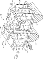
図1に示すのは、ターボファン式ガスタービンエンジン10の燃焼器及び高圧タービン部分である。エンジン10は、中心軸線8の周りに画定されており、下流方向に直列に流体連通した状態で、ファン(図示せず)と、多段式軸流圧縮機12(一部を示す)と、環状の燃焼器14と、2段式高圧タービン16と、多段式低圧タービン(図示せず)とを含む。運転時、空気18は、圧縮機内で加圧され燃焼器内で燃料と混合されて、高温の燃焼ガス20を発生し、該燃焼ガス20は、高圧及び低圧タービンを通って下流方向に流れ、該タービンが燃焼ガスからエネルギーを取り出す。高圧タービンは、圧縮機に動力を供給し、また低圧タービンは、従来型の構成でファンに動力を供給し、離陸から、巡航、降下、そして着陸まで飛行中の航空機を推進する。
FIG. 1 shows a combustor and a high-pressure turbine portion of a turbofan
図2に更に示すのは、下流方向に直列に流体連通した状態の高圧タービン16の第1段19及び第2段20である。第1段19は、下流方向に直列に流体連通した状態で、第1ベーン列25を有する第1ノズル23と第1ロータブレード列29を有する第1ロータ段27とを含む。第2段21は、下流方向に直列に流体連通した状態で、第2ベーン列35を有する第2ノズル33と第2ロータブレード列39を有する第2ロータ段37とを含む。ブレード及びベーン列の各々は、高温ガス流路28を横切って延びるタービン翼形部22の列を含む。タービン翼形部22は、下流方向51に前縁LEから後縁TEまで延びる翼弦長CLを有する。
Further shown in FIG. 2 are a first stage 19 and a
エンジン10は、アイドリングから離陸、巡航、降下、及び着陸まで変化する運転状況又は出力で作動する。作動の間に発生する燃焼ガス20の最高温度は、一時的にかつ様々な運転状況に対応して変化する。エンジンの運転中に燃焼器14から吐出される燃焼ガス20は、タービン翼形部22の間で円周方向及び半径方向の両方向に変化する空間的な温度分布を有する。翼形部22の上流列34により発生する不安定な高温ストリークは、次ぎの翼形部の下流列36に影響を与える。翼形部22は、熱保護が行われ、十分な熱耐性すなわち高温性能を有して、流れの異常が引き起こす高温環境に耐えなければならない。タービン翼形部22は、エンジン運転中に高温の燃焼ガス20を浴びせられるので、一定程度の高温性能を有していなければならない。従来から、タービン翼形部22が設置される段において燃焼ガス20がどのくらい高温であるかに応じて、異なる段における翼形部に対して異なる程度の高温性能が用いられている。高圧タービン16における燃焼ガス20は、低圧タービンにおけるよりも遙かに高温である。温度分布は、従来の方法だけでなく実験に基づく最新式三次元演算流体力学(CFD)ソフトウェアを用いて解析的に決定することが可能である。
The
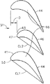
更に図3を参照すると、第1ロータ段27における第1ロータブレード列29内と第2段21における第2ベーン列35及び第2ロータブレード列39内とのタービン翼形部22の列は、第1翼弦長CL1を有する第1の複数41の第1翼形部44と該第1翼弦長CL1より短い第2翼弦長CL2を有する第2の複数43の第2翼形部46とを含む。第2翼形部46の少なくとも1つは、円周方向に第1翼形部44の各対66の間に配置される。第2翼形部46の第2前縁47は、距離Dだけ第1翼形部44の第1前縁53から下流に位置する。翼形部の製造費用及びエンジンの運転費用の両方を節減するために、第1及び第2翼形部44及び46は、それぞれ異なる第1及び第2の高温性能を有しており、該第1の高温性能は、該第2の高温性能より高い。第2翼形部46の1つ又はそれ以上を、図4に示すように円周方向に第1翼形部44の各対66の間に配置することができ、図4においては、第2翼形部46の2つが円周方向に第1翼形部44の各対66の間に配置されている。
Still referring to FIG. 3, the rows of
第2翼形部46の第2前縁47は第1翼形部44の第1前縁53から下流に位置しているために、より長い第1翼弦長CL1を有する第1翼形部44は、翼形部の上流列34により発生される不安定な高温ストリークから第2翼形部46を隠す。より短い第2翼弦長CL2を有する第2翼形部46は、より低温の環境で作動するので、必要な冷却空気流48はより少なくて済み、それほど高価な材料を必要としないし、又はより高水準の寿命の部品を産生することになる。第2翼形部のより低い第2の高温性能は、より少ない冷却空気流しか必要とせずかつより安価な材料しか必要としない第2翼形部を使用することを可能にする。より少ない冷却流量により、構成部品又はエンジンはより効率的なものになる。
Since the second
翼形部22の1つの例示的な実施形態では、第2翼形部46は、第1翼形部44より、より少ない量の冷却空気流48を使用するよう構成される。翼形部22の別の例示的な実施形態では、第1及び第2翼形部44及び46は、異なる合金から構成される。翼形部22の更に別の例示的な実施形態では、前の2つの実施形態の組合せが用いられ、第2翼形部46は、第1翼形部44より、より少ない量の冷却空気流48を使用するよう構成され、また第1及び第2翼形部44及び46は、異なる合金から構成される。
In one exemplary embodiment of
再び図2を参照すると、HPT内のタービン翼形部22は一般的に、例えば様々な内部及び外部冷却構造を用いて従来の方法で冷却される。圧縮機空気18の一部分が、圧縮機から反らされ、幾つかの翼形部を通して流されて該翼形部を内部冷却するための冷却空気として用いられる。翼形部22は、少なくとも1つの内部冷却空気流回路40と該翼形部22の対向する正圧側壁及び負圧側壁を貫通して冷却空気を冷却空気流回路40からガス流路28内に吐出するフィルム冷却孔すなわち開口42とを含む。開口は、フィルム冷却孔及び/又は後縁スロット38の列の形態で構成することができ、また各翼形部のどちらか一方又は両方の側壁に配置することができる。各翼形部22の内部からの冷却空気は、様々な開口を通して吐出されて、翼形部の外部表面上に冷却空気の保護フィルムを形成して高温燃焼ガスからの付加的な保護を行う。
Referring again to FIG. 2, the
本発明は、単一段の高圧タービン又は二重反転式ロータを備える高圧タービン内で用いることができる。 The present invention can be used in a single stage high pressure turbine or a high pressure turbine with a counter-rotating rotor.
本発明を、例示による方法で説明した。用いた用語は、本質的には限定するものではなく説明することを意図するものであることを理解されたい。本明細書中では本発明の好ましくかつ例示的な実施形態であると考えられるものを説明してきたが、本明細書における教示から本発明の他の変更形態が当業者には明らかになるものであり、従って、そのような変更形態は、本発明の技術思想及び技術的範囲内に含まれるものとして、特許請求の範囲で保護されることを望む。 The present invention has been described in an illustrative manner. It is to be understood that the terminology used is intended to be illustrative rather than limiting in nature. While what has been described herein is considered to be a preferred and exemplary embodiment of the present invention, other modifications of the present invention will become apparent to those skilled in the art from the teachings herein. Therefore, such modifications are intended to be protected by the following claims as falling within the spirit and scope of the present invention.
なお、特許請求の範囲に記載された符号は、理解容易のためであってなんら発明の技術的範囲を実施例に限縮するものではない。 In addition, the code | symbol described in the claim is for easy understanding, and does not limit the technical scope of an invention to an Example at all.
8 中心軸線
10 ガスタービンエンジン
12 多段式軸流圧縮機
14 燃焼器
16 2段式高圧タービン
18 空気
19 高圧タービンの第1段
20 高温燃焼ガス
21 高圧タービンの第2段
22 タービン翼形部
23 第1ノズル
27 第1ロータ段
28 高温ガス流路
29 ロータブレード
33 第2ノズル
35 第2ベーン列
37 第2ロータ段
39 第2ロータブレード列
42 フィルム冷却孔
51 下流方向
8
Claims (10)
第1翼弦長(CL1)を有する第1の複数(41)の第1翼形部(44)と、
前記第1翼弦長より短い第2翼弦長(CL2)を有する第2の複数(43)の第2翼形部(46)と、を含み、
前記第2翼形部の少なくとも1つが、円周方向に前記第1翼形部の各隣接対(66)の間に配置され、
前記第2翼形部の第2前縁(47)が、前記第1翼形部の第1前縁(53)から下流に位置し、
前記第1及び第2翼形部が、それぞれ異なる第1及び第2の熱耐性を有しており、前記第1の熱耐性が、前記第2の熱耐性より高い、
ことを特徴とするガスタービンエンジンタービン段(19)組立体。 An annular row of turbine airfoils (22);
A first plurality (41) of first airfoils (44) having a first chord length (CL1);
A second plurality (43) of second airfoils (46) having a second chord length (CL2) shorter than the first chord length;
At least one of the second airfoils is circumferentially disposed between each adjacent pair (66) of the first airfoils;
A second leading edge (47) of the second airfoil is located downstream from a first leading edge (53) of the first airfoil;
The first and second airfoils have different first and second heat resistances , respectively, and the first heat resistance is higher than the second heat resistance ;
A gas turbine engine turbine stage (19) assembly characterized by:
前記第2翼形部の第2前縁(47)が、前記第1翼形部の第1前縁(53)から下流に位置している、
ことを特徴とする、請求項1に記載の組立体。 Further comprising one or more of said second airfoils, disposed circumferentially between each adjacent pair (66) of said first airfoils,
A second leading edge (47) of the second airfoil is located downstream from a first leading edge (53) of the first airfoil ;
The assembly according to claim 1, wherein:
前記タービン翼形部(22)の環状の下流列(36)が、第1翼弦長(CL1)を有する第1の複数(41)の第1翼形部(44)と前記第1翼弦長より短い第2翼弦長(CL2)を有する第2の複数(43)の第2翼形部(46)とを含み、
前記第2翼形部の各々の少なくとも1つが、円周方向に前記第1翼形部の各隣接対(66)の間に配置され、
前記第2翼形部の第2前縁(47)が、前記第1翼形部の第1前縁(53)から下流に位置し、
前記第1及び第2翼形部が、それぞれ異なる第1及び第2の熱耐性を有しており、前記第1の熱耐性が、前記第2の熱耐性より高い、
ことを特徴とするガスタービンエンジンタービン段(19)組立体。 An axially adjacent annular upstream row (34) and downstream row (36) of turbine airfoils (22);
An annular downstream row (36) of the turbine airfoil (22) includes a first plurality (41) of first airfoils (44) having a first chord length (CL1) and the first chord. A second plurality (43) of second airfoils (46) having a second chord length (CL2) shorter than the length;
At least one of each of the second airfoils is circumferentially disposed between each adjacent pair (66) of the first airfoils;
A second leading edge (47) of the second airfoil is located downstream from a first leading edge (53) of the first airfoil;
The first and second airfoils have different first and second heat resistances , respectively, and the first heat resistance is higher than the second heat resistance ;
A gas turbine engine turbine stage (19) assembly characterized by:
Applications Claiming Priority (1)
| Application Number | Priority Date | Filing Date | Title |
|---|---|---|---|
| US10/305,833 US7094027B2 (en) | 2002-11-27 | 2002-11-27 | Row of long and short chord length and high and low temperature capability turbine airfoils |
Publications (3)
| Publication Number | Publication Date |
|---|---|
| JP2004176723A JP2004176723A (en) | 2004-06-24 |
| JP2004176723A5 JP2004176723A5 (en) | 2007-01-18 |
| JP4366178B2 true JP4366178B2 (en) | 2009-11-18 |
Family
ID=32298066
Family Applications (1)
| Application Number | Title | Priority Date | Filing Date |
|---|---|---|---|
| JP2003396596A Expired - Fee Related JP4366178B2 (en) | 2002-11-27 | 2003-11-27 | Turbine airfoil section with long and short chord lengths and high and low temperature performance |
Country Status (4)
| Country | Link |
|---|---|
| US (1) | US7094027B2 (en) |
| EP (1) | EP1424467A3 (en) |
| JP (1) | JP4366178B2 (en) |
| CA (1) | CA2449263C (en) |
Families Citing this family (39)
| Publication number | Priority date | Publication date | Assignee | Title |
|---|---|---|---|---|
| JP4354358B2 (en) * | 2004-07-15 | 2009-10-28 | 三菱重工業株式会社 | Life diagnosis method for high temperature components in gas turbines |
| DE102004036594A1 (en) * | 2004-07-28 | 2006-03-23 | Mtu Aero Engines Gmbh | Flow structure for a gas turbine |
| US7377743B2 (en) * | 2005-12-19 | 2008-05-27 | General Electric Company | Countercooled turbine nozzle |
| US7695241B2 (en) * | 2006-11-30 | 2010-04-13 | General Electric Company | Downstream plasma shielded film cooling |
| US7588413B2 (en) * | 2006-11-30 | 2009-09-15 | General Electric Company | Upstream plasma shielded film cooling |
| US7628585B2 (en) * | 2006-12-15 | 2009-12-08 | General Electric Company | Airfoil leading edge end wall vortex reducing plasma |
| US7736123B2 (en) * | 2006-12-15 | 2010-06-15 | General Electric Company | Plasma induced virtual turbine airfoil trailing edge extension |
| ATE447662T1 (en) * | 2007-01-18 | 2009-11-15 | Siemens Ag | GUIDE VANE FOR A GAS TURBINE |
| US7836703B2 (en) * | 2007-06-20 | 2010-11-23 | General Electric Company | Reciprocal cooled turbine nozzle |
| US20090317237A1 (en) * | 2008-06-20 | 2009-12-24 | General Electric Company | System and method for reduction of unsteady pressures in turbomachinery |
| US8540490B2 (en) * | 2008-06-20 | 2013-09-24 | General Electric Company | Noise reduction in a turbomachine, and a related method thereof |
| US8677763B2 (en) * | 2009-03-10 | 2014-03-25 | General Electric Company | Method and apparatus for gas turbine engine temperature management |
| US8684684B2 (en) * | 2010-08-31 | 2014-04-01 | General Electric Company | Turbine assembly with end-wall-contoured airfoils and preferenttial clocking |
| ES2583756T3 (en) * | 2011-04-01 | 2016-09-22 | MTU Aero Engines AG | Blade arrangement for a turbomachine |
| US8790067B2 (en) | 2011-04-27 | 2014-07-29 | United Technologies Corporation | Blade clearance control using high-CTE and low-CTE ring members |
| GB201108001D0 (en) * | 2011-05-13 | 2011-06-29 | Rolls Royce Plc | A method of reducing asymmetric fluid flow effect in a passage |
| US8739547B2 (en) | 2011-06-23 | 2014-06-03 | United Technologies Corporation | Gas turbine engine joint having a metallic member, a CMC member, and a ceramic key |
| US8864492B2 (en) | 2011-06-23 | 2014-10-21 | United Technologies Corporation | Reverse flow combustor duct attachment |
| US9335051B2 (en) | 2011-07-13 | 2016-05-10 | United Technologies Corporation | Ceramic matrix composite combustor vane ring assembly |
| US8920127B2 (en) | 2011-07-18 | 2014-12-30 | United Technologies Corporation | Turbine rotor non-metallic blade attachment |
| ITTO20110728A1 (en) * | 2011-08-04 | 2013-02-05 | Avio Spa | STATIC PALLETED SEGMENT OF A GAS TURBINE FOR AERONAUTICAL MOTORS |
| US20140208758A1 (en) * | 2011-12-30 | 2014-07-31 | Clearsign Combustion Corporation | Gas turbine with extended turbine blade stream adhesion |
| US20130167552A1 (en) * | 2012-01-04 | 2013-07-04 | General Electric Company | Exhaust strut and turbomachine incorprating same |
| US8424313B1 (en) | 2012-01-31 | 2013-04-23 | United Technologies Corporation | Gas turbine engine mid turbine frame with flow turning features |
| ITMI20120779A1 (en) * | 2012-05-08 | 2013-11-09 | Franco Tosi Meccanica S P A | ROTORIAL STAGE OF AXIAL TURBINE WITH AN IMPROVED EROSION PROTECTION |
| EP2685050B1 (en) * | 2012-07-11 | 2017-02-01 | General Electric Technology GmbH | Stationary vane assembly for an axial flow turbine |
| GB201303767D0 (en) | 2013-03-04 | 2013-04-17 | Rolls Royce Plc | Stator Vane Row |
| US9938984B2 (en) | 2014-12-29 | 2018-04-10 | General Electric Company | Axial compressor rotor incorporating non-axisymmetric hub flowpath and splittered blades |
| US9874221B2 (en) | 2014-12-29 | 2018-01-23 | General Electric Company | Axial compressor rotor incorporating splitter blades |
| US20180010459A1 (en) * | 2016-01-11 | 2018-01-11 | United Technologies Corporation | Low energy wake stage |
| US10436068B2 (en) * | 2016-02-12 | 2019-10-08 | General Electric Company | Flowpath contouring |
| GB201615494D0 (en) * | 2016-09-13 | 2016-10-26 | Rolls Royce Plc | Rotor stage |
| EP3372785A1 (en) * | 2017-03-09 | 2018-09-12 | General Electric Company | Turbine airfoil arrangement incorporating splitters |
| GB201806631D0 (en) | 2018-04-24 | 2018-06-06 | Rolls Royce Plc | A combustion chamber arrangement and a gas turbine engine comprising a combustion chamber arrangement |
| GB201818347D0 (en) * | 2018-11-12 | 2018-12-26 | Rolls Royce Plc | Rotor blade arrangement |
| DE102019200885A1 (en) * | 2019-01-24 | 2020-07-30 | MTU Aero Engines AG | Guide grille for a turbomachine |
| US12037921B2 (en) | 2022-08-04 | 2024-07-16 | General Electric Company | Fan for a turbine engine |
| US12503980B2 (en) | 2022-11-01 | 2025-12-23 | General Electric Company | Gas turbine engine |
| US12540551B1 (en) | 2025-07-01 | 2026-02-03 | General Electric Company | Gas turbine engines including splittered airfoils |
Family Cites Families (19)
| Publication number | Priority date | Publication date | Assignee | Title |
|---|---|---|---|---|
| US910266A (en) * | 1906-12-17 | 1909-01-19 | Giuseppe Belluzzo | Elastic-fluid turbine. |
| US2406499A (en) * | 1943-08-23 | 1946-08-27 | Bendix Aviat Corp | Fluid transmission |
| US3039736A (en) * | 1954-08-30 | 1962-06-19 | Pon Lemuel | Secondary flow control in fluid deflecting passages |
| US2920864A (en) * | 1956-05-14 | 1960-01-12 | United Aircraft Corp | Secondary flow reducer |
| US3347520A (en) * | 1966-07-12 | 1967-10-17 | Jerzy A Oweczarek | Turbomachine blading |
| US3704075A (en) * | 1970-12-14 | 1972-11-28 | Caterpillar Tractor Co | Combined turbine nozzle and bearing frame |
| GB2115881A (en) * | 1982-02-26 | 1983-09-14 | Rolls Royce | Gas turbine engine stator vane assembly |
| US4624104A (en) * | 1984-05-15 | 1986-11-25 | A/S Kongsberg Vapenfabrikk | Variable flow gas turbine engine |
| US4758129A (en) * | 1985-05-31 | 1988-07-19 | General Electric Company | Power frame |
| US5152661A (en) * | 1988-05-27 | 1992-10-06 | Sheets Herman E | Method and apparatus for producing fluid pressure and controlling boundary layer |
| GB2258272B (en) * | 1991-07-27 | 1994-12-07 | Rolls Royce Plc | Rotors for turbo machines |
| US5299914A (en) * | 1991-09-11 | 1994-04-05 | General Electric Company | Staggered fan blade assembly for a turbofan engine |
| FR2706534B1 (en) * | 1993-06-10 | 1995-07-21 | Snecma | Multiflux diffuser-separator with integrated rectifier for turbojet. |
| US5634768A (en) * | 1994-11-15 | 1997-06-03 | Solar Turbines Incorporated | Airfoil nozzle and shroud assembly |
| US5706647A (en) * | 1994-11-15 | 1998-01-13 | Solar Turbines Incorporated | Airfoil structure |
| US5584652A (en) * | 1995-01-06 | 1996-12-17 | Solar Turbines Incorporated | Ceramic turbine nozzle |
| US6197424B1 (en) * | 1998-03-27 | 2001-03-06 | Siemens Westinghouse Power Corporation | Use of high temperature insulation for ceramic matrix composites in gas turbines |
| EP0978632A1 (en) * | 1998-08-07 | 2000-02-09 | Asea Brown Boveri AG | Turbomachine with intermediate blades as flow dividers |
| US6402458B1 (en) * | 2000-08-16 | 2002-06-11 | General Electric Company | Clock turbine airfoil cooling |
-
2002
- 2002-11-27 US US10/305,833 patent/US7094027B2/en not_active Expired - Fee Related
-
2003
- 2003-11-13 CA CA2449263A patent/CA2449263C/en not_active Expired - Fee Related
- 2003-11-26 EP EP03257438A patent/EP1424467A3/en not_active Withdrawn
- 2003-11-27 JP JP2003396596A patent/JP4366178B2/en not_active Expired - Fee Related
Also Published As
| Publication number | Publication date |
|---|---|
| EP1424467A2 (en) | 2004-06-02 |
| US20040101405A1 (en) | 2004-05-27 |
| JP2004176723A (en) | 2004-06-24 |
| EP1424467A3 (en) | 2006-09-27 |
| CA2449263C (en) | 2010-11-09 |
| CA2449263A1 (en) | 2004-05-27 |
| US7094027B2 (en) | 2006-08-22 |
Similar Documents
| Publication | Publication Date | Title |
|---|---|---|
| JP4366178B2 (en) | Turbine airfoil section with long and short chord lengths and high and low temperature performance | |
| JP4733876B2 (en) | Cooling turbine airfoils offset in clockwise direction | |
| US5690473A (en) | Turbine blade having transpiration strip cooling and method of manufacture | |
| US8529193B2 (en) | Gas turbine engine components with improved film cooling | |
| US5593276A (en) | Turbine shroud hanger | |
| EP2578803B1 (en) | Methods and systems for use in regulating a temperature of components | |
| US6612807B2 (en) | Frame hub heating system | |
| US7377743B2 (en) | Countercooled turbine nozzle | |
| US20110311369A1 (en) | Gas turbine engine components with cooling hole trenches | |
| EP2746536A1 (en) | Rotor stage of a turbine | |
| EP2568119B1 (en) | Airfoil for a gas turbine engine with an improved trailing edge cooling arrangement | |
| US20130315710A1 (en) | Gas turbine engine components with cooling hole trenches | |
| JP2009002340A (en) | Reciprocal cooling turbine nozzle | |
| EP3816408B1 (en) | Negative thermal expansion compressor case for improved tip clearance | |
| US20160069194A1 (en) | Turbine blades and methods of forming turbine blades having lifted rib turbulator structures | |
| CA2861175C (en) | Internally cooled airfoil | |
| JPS6258001A (en) | Air control means | |
| US9816389B2 (en) | Turbine rotor blades with tip portion parapet wall cavities | |
| CN113279857A (en) | High thrust-weight ratio gas turbine generator suitable for unmanned aerial vehicle | |
| EP3889392B1 (en) | Turbomachine rotor blade with a cooling circuit having an offset rib | |
| GB2366600A (en) | Cooling arrangement for trailing edge of aerofoil | |
| JPS6215724B2 (en) |
Legal Events
| Date | Code | Title | Description |
|---|---|---|---|
| A521 | Written amendment |
Free format text: JAPANESE INTERMEDIATE CODE: A523 Effective date: 20061127 |
|
| A621 | Written request for application examination |
Free format text: JAPANESE INTERMEDIATE CODE: A621 Effective date: 20061127 |
|
| A131 | Notification of reasons for refusal |
Free format text: JAPANESE INTERMEDIATE CODE: A131 Effective date: 20090331 |
|
| A521 | Written amendment |
Free format text: JAPANESE INTERMEDIATE CODE: A523 Effective date: 20090626 |
|
| RD02 | Notification of acceptance of power of attorney |
Free format text: JAPANESE INTERMEDIATE CODE: A7422 Effective date: 20090626 |
|
| RD04 | Notification of resignation of power of attorney |
Free format text: JAPANESE INTERMEDIATE CODE: A7424 Effective date: 20090626 |
|
| TRDD | Decision of grant or rejection written | ||
| A01 | Written decision to grant a patent or to grant a registration (utility model) |
Free format text: JAPANESE INTERMEDIATE CODE: A01 Effective date: 20090728 |
|
| A01 | Written decision to grant a patent or to grant a registration (utility model) |
Free format text: JAPANESE INTERMEDIATE CODE: A01 |
|
| A61 | First payment of annual fees (during grant procedure) |
Free format text: JAPANESE INTERMEDIATE CODE: A61 Effective date: 20090824 |
|
| FPAY | Renewal fee payment (event date is renewal date of database) |
Free format text: PAYMENT UNTIL: 20120828 Year of fee payment: 3 |
|
| R150 | Certificate of patent or registration of utility model |
Free format text: JAPANESE INTERMEDIATE CODE: R150 |
|
| LAPS | Cancellation because of no payment of annual fees |