JP4366021B2 - Page change device - Google Patents
Page change device Download PDFInfo
- Publication number
- JP4366021B2 JP4366021B2 JP2001021026A JP2001021026A JP4366021B2 JP 4366021 B2 JP4366021 B2 JP 4366021B2 JP 2001021026 A JP2001021026 A JP 2001021026A JP 2001021026 A JP2001021026 A JP 2001021026A JP 4366021 B2 JP4366021 B2 JP 4366021B2
- Authority
- JP
- Japan
- Prior art keywords
- shutter
- page
- turning
- roller
- opening
- Prior art date
- Legal status (The legal status is an assumption and is not a legal conclusion. Google has not performed a legal analysis and makes no representation as to the accuracy of the status listed.)
- Expired - Lifetime
Links
Images


Classifications
-
- B—PERFORMING OPERATIONS; TRANSPORTING
- B42—BOOKBINDING; ALBUMS; FILES; SPECIAL PRINTED MATTER
- B42D—BOOKS; BOOK COVERS; LOOSE LEAVES; PRINTED MATTER CHARACTERISED BY IDENTIFICATION OR SECURITY FEATURES; PRINTED MATTER OF SPECIAL FORMAT OR STYLE NOT OTHERWISE PROVIDED FOR; DEVICES FOR USE THEREWITH AND NOT OTHERWISE PROVIDED FOR; MOVABLE-STRIP WRITING OR READING APPARATUS
- B42D9/00—Bookmarkers; Spot indicators; Devices for holding books open; Leaf turners
- B42D9/04—Leaf turners
Description
【0001】
【発明の属する技術分野】
本発明は、通帳等の複数枚からなる冊子状媒体のページをめくる装置に関するものである。
【0002】
【従来の技術】
従来のページ替え装置では、特開昭7−81271号公報に記載されているように、シャッタは,その回転中心がページ替えローラと搬送ローラ内にあり,ページ替え時の紙の変形挙動により,持ち上がる構造であった。
【0003】
【発明が解決しようとする課題】
上記の従来技術においては、シャッタの重さがページ替え時の紙の変形挙動を阻害する要因となってしまい,ページ替えミスの原因となっていた。
【0004】
本発明の目的は、ページ替えミスを低減し、低コストで高性能なページ替え装置を提供することにある。
【0005】
【課題を解決するための手段】
本発明の上記の目的は、ページめくりローラの回転にリンクして,シャッタが開く構造にすることによって達成される。
【0006】
【発明の実施の形態】
以下、本発明の一実施例について図面を用いて詳細に説明する。
【0007】
図1(a)は、本発明のページ替え装置の平面図である。ページ替え装置は,ゴムなどの弾性材料による中空構造部と低摩擦芯金部を有するページ替えローラ3と、搬送ローラ5a,5cと,搬送方向に前後する順シャッタ2a,逆シャッタ2bと,その順シャッタ2a,逆シャッタ2bのリンク機構1とページ替えガイド4等によって、形成されている。前記シャッタ2a,2bの幅aは世界中の通帳を調査した結果,最小幅を示しており,幅bは最大幅を示している。シャッタ2a,2bの幅は少なくとも,幅bより大きい。また,ページ替えローラ3は少なくとも,幅a内に配置されている。
【0008】
図1(b)は,本発明のページ替え装置の側面図である。ページ替え装置は,前記リンク1は,カム1aと順リンクアーム1b,逆リンクアーム1c,順リンク力点1d,逆リンク力点1e,順リンク支点1f,逆リンク支点1g,順リンク作用点1h,逆リンク作用点1i,搬送ローラ5a,5b,5c,5d,搬送路6等からなっている。これら部品構成が作用する装置内での使われ方としては、例えば通帳プリンタにおいて記帳の際に満行となり改頁が必要な場合(以下順めくり)と、通帳取引き者が未だ記帳可能な行が残っているにも関わらず誤って次の頁を開いて通帳プリンタに挿入した時、あるいは前記順めくりにおいて装置が誤って複数枚頁をめくった時に反対方向にめくり返す場合(以下逆めくり)がある。尚、本実施例中では順めくり時に作用が必要な部品とその動作の頭に「順」、逆めくり時に作用が必要な部品とその動作の頭に「逆」を名称として付けている。
【0009】
図2は,本発明の一実施例のリンク機構を示す。めくり動作を行うと、めくりローラ3(図示省略)とカム1aは同期して回転する。回転方向Aに回転したカム1aaはローラ状の逆リンク力点1eと接触する。これによって,逆リンクアーム1cは逆リンク支点1gを中心に回動し,逆リンク作用点1iが逆シャッタ2bと接触しつつ開閉できるように上下動をおこなう。
【0010】
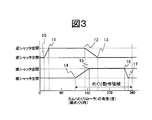
この動作を横軸をカム1aの回転角にとってみると,図3に示すようになる。図3を用いて,逆シャッタ動作を説明する。前記回転したカム1aaとローラ状の逆リンク力点1eが接触し(10),シャッタ2bが開き始める。さらに,カム1aaが回転し,該カム1aaの最外周と逆リンク力点1eが接触し始めと(11),該シャッタ2bは最大角開いた状態を保つ。カム1aaのエッジまでくると(12),該シャッタ2bは徐々に閉じ始め,前記カム1aaと逆リンク力点1eが非接触になり(13),該シャッタ2bは閉じる。同様に,回転方向Bに回転したカム1abはローラ状の順リンク力点1dと接触する。これによって,順リンクアーム1bは順リンク支点1fを中心に回動し,順リンク作用点1hが順シャッタ2aと接触しつつ開閉できるように上下動をおこなう。
【0011】
次に図3を用いて,順シャッタ動作を説明する。前記回転したカム1abとローラ状の順リンク力点1dが接触し(14),シャッタ2aが開き始める。さらに,カム1abが回転し,該カム1abの最外周と順リンク力点1dが接触し始めと(15),該シャッタ2aは最大角開いた状態を保つ。カム1abのエッジまでくると(16),該シャッタ2aは徐々に閉じ始め,前記カム1abと順リンク力点1dが非接触になり(17),該シャッタ2aは閉じる。本実施例では,順めくりおよび逆めくり動作を一つの駆動軸より行うため,カム1aの回転角180度を中心に順シャッタ2a,逆シャッタ2bの動きは対称となる。すなわち,順めくりを行う時には,実際のめくり動作領域となる前に逆側のシャッタが開く。実際にはめくり動作領域はおおむねめくりローラ3が通帳と接触する直前,すなわち180度より手前で開いてめくったページがシャッタ2aあるいは2bと接触しなければ良いのだから,逆側のシャッタが前記の動作をしても問題はない。
【0012】
図4を用いて,本発明の一実施例のページ替えガイドとページ替えローラ3の関係について,説明する。ページ替えガイドは順めくり用ページ替えガイド4と逆めくり用ページ替えガイド4cがあり、それらは頁替えローラ3の左右にそれぞれ配置されている(図1(a)参照)。まず図4(a)で順めくり用ページ替えガイド4について説明する。なお,順めくり用ページ替えガイド4と逆めくり用ページ替えガイド4cとは,中心軸20において,左右対称形である。ページ替えローラ3の芯金部の順めくり用突起部3a(本図表面側)は,前記順ページ替えガイド4の側面4a(太線部)に初期状態では接触している。また,初期状態では,端面4bは,シャッタ2aの開閉時の回転範囲内に位置し,該シャッタ2aの開く動作を阻止するように位置している。ページ替えローラ3が回転方向Aに回転し始めると,前記順めくり用突起部3aと側面4aは,一旦非接触状態になる。
【0013】
さらに,該ページ替えローラ3が回転すると,再び,側面4aの一部と前記順めくり用突起部3aが接触し始める。しばらく,回転すると,前記順ページ替えガイド4は,回転軸21を回転中心として,回転方向Cに回転し始める。これにより,前記順ページ替えガイド4の一部である端面4bが横方向に移動する。該端面4bは,前記シャッタ2aが開くことを防止していたが,該移動により,該シャッタ2aが開くことが可能となる。図4(b)は逆めくり用頁替えガイド4cの作用を示す。頁替えローラ3が回転方向Bに回転する事で逆めくり用突起部3b(本図裏面側)が逆めくり用ページ替えガイド4cの側面4aを押して回転方向C'に移動させて,逆めくり用シャッタ2bが開くことを可能にしている。
【0014】
また、ページ替えローラ3が回転方向Bに回転する時、すなわち逆めくり起動時、図4(a)において順めくり用突起部3aは やはり順めくり用ページ替えガイド4の側面4aに即、接し、順めくり用ページ替えガイド4は回転方向Cに回転する事で端面4bが上記同様の横方向に移動し、順めくり用シャッタ2aの押えを解除、結果順めくり用シャッタ2aは逆めくり時に本来開く事が必須である逆めくり用シャッタよりいち早く開く事になる。また、頁替えローラ3が回転方向Aに回転するときすなわち順めくり起動時は図4(b)において逆めくり用突起部3bは逆めくり用頁替えガイド4cの側面4aに即、接し、逆めくり用頁替えガイド4cは回転方向C'に回転する事で端面4bが上記同様横方向に移動し逆めくり用シャッタ2bの押えを解除、結果逆めくり用シャッタ2bは順めくり時に本来開く事が必須である順めくり用シャッタ2aよりいち早く開く事になる。このことは前記図3のシャッタ開閉のタイミングチャートを説明したように一つの駆動軸で順めくり用と逆めくり用のシャッタ開閉を行わせる為、駆動軸は回転方向に関わらず360°回転すれば、それぞれのシャッタは必要とするめくりの用途に関わらず前記図3タイミングチャートのごとき必ず1回は開閉動作を行う事になる。そこで、順逆頁めくり用ガイド4と4cは、頁替えローラ3の回転方向ABいずれにおいてもシャッタ開閉の動きに連動してシャッタの押え解除を行う動きを必要とする訳である。
【0015】
図5から図7を用いて,本発明における順めくり動作を説明する。通帳8は,搬送ローラによって,搬送路6内を搬送され,所定の位置で挟持されている(図5(a))。ページ替えローラ3が回転し始めると,リンク機構1のカム1aaも同様に回転し始める。該カム1aaが逆リンク力点1eに接触し始める。すると,逆リンク支点1gを中心に逆リンク1cが回転方向Dに回転し始め,逆リンク作用点1iが逆シャッタ2bを押し上げ,該逆シャッタ2bは,回転方向Eに回転し始める(図5(b))。さらに,前記ページ替えローラ3が回転すると,前記逆シャッタ2bは最大角度開く(図5(c))。引き続き,該ページ替えローラ3が回転すると,カム1abが順リンク力点1dに接触し始める。すると,順リンク支点1fを中心に順リンク1bが回転方向Fに回転し始め,順リンク作用点1hが順シャッタ2aを押し上げ,該順シャッタ2aは,回転方向Gに回転し始める(図6(d))。ここで,ページ替えローラ3の芯金部が通帳8に接触し始め,該通帳8は,ペーパパン7の突起部7aを支点に曲げの1次モードで曲げられる。
【0016】
該ページ替えローラ3が回転を続けると,前記順シャッタ2aはその最大開き角度まで開く(図6(e))。該ページ替えローラ3のゴム等の高摩擦弾性部材の中空構造した摩擦部が,前記通帳8の表面のページ8aに接触し,めくりあがり始める(図6(f))。その際,逆シャッタ2bは閉じ始める。さらに,該ページ替えローラ3が回転すると,逆シャッタ2bは閉じる(図7(g))。ページ8aは大きくめくれあがり,前記カム1abは順リンク力点1dと非接触となり,順リンクアーム1bは,回転方向Hに回転し始める。同時に,該順シャッタ2aは回転方向Iに閉じ始める(図7(h))。ページ替えローラ3が初期角度に戻ると,順リンク1bは,初期位置に戻り,前記シャッタ2aを押し上げている順リンク作用点1hから開放されるが,めくり上がったページ8aにより,前記シャッタ2aは開いたの状態を保つ。そして,通帳8を搬送方向Jに搬送することで,ページ替えが終了する(図7(i))。以上が順めくり動作であるが、逆めくり動作においては頁替えローラ3の中心を左右鏡面対称形にした動作となるものである。
【0017】
【発明の効果】
本発明によれば、低コストで高性能なページ替え装置提供できるという効果がある。
【0018】
【図面の簡単な説明】
【図1】本発明を適用したページ替え装置の平面図および側面図。
【図2】本発明のリンク機構の平面図および側面図。
【図3】本発明のシャッタ動作を示すタイミングチャート
【図4】本発明を適用したページ替えローラとページ替えガイドの位置関係図
【図5】本発明を適用したページ替え装置の動作図。
【図6】本発明を適用したページ替え装置の動作図。
【図7】本発明を適用したページ替え装置の動作図。
【符号の説明】
1…リンク機構、2…シャッタ、3…ページ替えローラ、4…順ページ替えガイド、4a…ページ替えガイド側面、5…搬送ローラ、6…搬送路、7…ペーパパン、7a…突起部、8…通帳、8a…めくったページ[0001]
BACKGROUND OF THE INVENTION
The present invention relates to an apparatus for turning a page of a booklet-shaped medium composed of a plurality of sheets such as a passbook.
[0002]
[Prior art]
In the conventional page changing device, as described in JP-A-7-81271, the shutter has a rotation center in the page changing roller and the conveying roller, and due to the deformation behavior of the paper at the time of page changing, It was a lifting structure.
[0003]
[Problems to be solved by the invention]
In the above prior art, the weight of the shutter becomes a factor that hinders the deformation behavior of the paper at the time of page change, causing a page change error.
[0004]
An object of the present invention is to provide a low-cost and high-performance page change device that reduces page change mistakes.
[0005]
[Means for Solving the Problems]
The above object of the present invention can be achieved by providing a structure in which the shutter is opened linked to the rotation of the page turning roller.
[0006]
DETAILED DESCRIPTION OF THE INVENTION
Hereinafter, an embodiment of the present invention will be described in detail with reference to the drawings.
[0007]
FIG. 1A is a plan view of the page changing apparatus of the present invention. The page changing device includes a
[0008]
FIG.1 (b) is a side view of the page change apparatus of this invention. In the page changing device, the
[0009]
FIG. 2 shows a link mechanism according to an embodiment of the present invention. When the turning operation is performed, the turning roller 3 (not shown) and the cam 1a rotate in synchronization. The cam 1aa rotated in the rotation direction A comes into contact with the roller-shaped reverse
[0010]
FIG. 3 shows this operation when the horizontal axis is taken with respect to the rotation angle of the cam 1a. The reverse shutter operation will be described with reference to FIG. The rotated cam 1aa contacts the roller-like reverse
[0011]
Next, the forward shutter operation will be described with reference to FIG. The rotated cam 1ab contacts the roller-like forward
[0012]
The relationship between the page change guide and the
[0013]
Furthermore, when the
[0014]
Further, when the
[0015]
The turning operation in the present invention will be described with reference to FIGS. The
[0016]
When the
[0017]
【The invention's effect】
According to the present invention, it is possible to provide a low-cost and high-performance page changing device.
[0018]
[Brief description of the drawings]
FIG. 1 is a plan view and a side view of a page changing apparatus to which the present invention is applied.
FIG. 2 is a plan view and a side view of the link mechanism of the present invention.
FIG. 3 is a timing chart showing the shutter operation of the present invention. FIG. 4 is a positional relationship diagram of a page changing roller and a page changing guide to which the present invention is applied. FIG. 5 is an operation diagram of a page changing apparatus to which the present invention is applied.
FIG. 6 is an operation diagram of the page changing apparatus to which the present invention is applied.
FIG. 7 is an operation diagram of the page changing apparatus to which the present invention is applied.
[Explanation of symbols]
DESCRIPTION OF
Claims (3)
該ローラを駆動するアクチュエータ等からなるページめくり手段と、
冊子を搬送する搬送ローラと、搬送路を構成する上下の固定された搬送ガイドと、ページめくり挙動に必要な空間を確保するために開閉可能なシャッタと、該シャッタの開閉手段とで構成される搬送手段と
を有するページ替え装置において、
前記ページめくりローラの回転駆動源を上記シャッタの開閉手段の開閉駆動源として共用し、前記ページめくりローラと連動して前記シャッタを開閉する構成を有するものであって、
通帳搬送路上の通帳がページめくり時に狭持される位置であり前記ページめくりローラの冊子搬送方向前後に2個の突起部を設け、ページめくり時は該突起部を支点に通帳が曲げられ、
前記下側搬送ガイドにおける2個の突起部の間を、該2個の突起部の外側よりも凹ませて構成し、
前記ページめくりローラと同一の駆動源にてシャッタの開閉動作を行うリンク機構を有し、該リンク機構は前記ページめくりローラがページをめくり上げる前に前記シャッタが開動作するよう作用し、ページがめくり上がった状態で当該開動作の作用を解放することを特徴とするページ替え装置。A booklet page turning roller,
Page turning means comprising an actuator or the like for driving the roller;
Consists of a conveyance roller for conveying a booklet, fixed upper and lower conveyance guides constituting a conveyance path, a shutter that can be opened and closed to secure a space necessary for page turning behavior, and an opening / closing means for the shutter In a page changing apparatus having a conveying means,
The rotation driving source of the page turning roller is shared as the opening / closing driving source of the shutter opening / closing means, and the shutter is opened and closed in conjunction with the page turning roller.
The passbook on the passbook conveyance path is a position that is sandwiched when turning pages , and is provided with two protrusions before and after the page turning direction of the page turning roller, and when turning pages, the passbook is bent with the protrusion as a fulcrum,
Between the two protrusions in the lower conveyance guide, is configured to be recessed from the outside of the two protrusions,
A link mechanism that opens and closes a shutter with the same drive source as the page turning roller, and the link mechanism acts to open the shutter before the page turning roller turns the page; A page changing apparatus, wherein the action of the opening operation is released in a state of being turned up.
Priority Applications (4)
| Application Number | Priority Date | Filing Date | Title |
|---|---|---|---|
| JP2001021026A JP4366021B2 (en) | 2001-01-30 | 2001-01-30 | Page change device |
| KR10-2001-0049675A KR100417270B1 (en) | 2001-01-30 | 2001-08-17 | Auto Page Turn Apparatus |
| DE10140790A DE10140790B4 (en) | 2001-01-30 | 2001-08-20 | flipper |
| CNB011257067A CN1196603C (en) | 2001-01-30 | 2001-08-20 | Leaf turner |
Applications Claiming Priority (1)
| Application Number | Priority Date | Filing Date | Title |
|---|---|---|---|
| JP2001021026A JP4366021B2 (en) | 2001-01-30 | 2001-01-30 | Page change device |
Publications (3)
| Publication Number | Publication Date |
|---|---|
| JP2002225461A JP2002225461A (en) | 2002-08-14 |
| JP2002225461A5 JP2002225461A5 (en) | 2005-06-16 |
| JP4366021B2 true JP4366021B2 (en) | 2009-11-18 |
Family
ID=18886646
Family Applications (1)
| Application Number | Title | Priority Date | Filing Date |
|---|---|---|---|
| JP2001021026A Expired - Lifetime JP4366021B2 (en) | 2001-01-30 | 2001-01-30 | Page change device |
Country Status (4)
| Country | Link |
|---|---|
| JP (1) | JP4366021B2 (en) |
| KR (1) | KR100417270B1 (en) |
| CN (1) | CN1196603C (en) |
| DE (1) | DE10140790B4 (en) |
Cited By (1)
| Publication number | Priority date | Publication date | Assignee | Title |
|---|---|---|---|---|
| JP5815152B1 (en) * | 2015-07-01 | 2015-11-17 | 株式会社新興製作所 | Page turning device |
Families Citing this family (5)
| Publication number | Priority date | Publication date | Assignee | Title |
|---|---|---|---|---|
| JP3491616B2 (en) * | 2001-02-27 | 2004-01-26 | 株式会社日立製作所 | Page turning apparatus and page turning method |
| JP4523295B2 (en) * | 2004-01-30 | 2010-08-11 | 富士通株式会社 | Page turning device |
| JP4784331B2 (en) * | 2006-02-20 | 2011-10-05 | 沖電気工業株式会社 | Automatic page break mechanism |
| CN106113982B (en) * | 2016-08-23 | 2018-02-23 | 江西伊贝基科技有限公司 | A kind of page page turning catching robot |
| CN109466205A (en) * | 2018-12-24 | 2019-03-15 | 佛山科学技术学院 | A kind of automatic leaf turner |
Family Cites Families (3)
| Publication number | Priority date | Publication date | Assignee | Title |
|---|---|---|---|---|
| JPH0796347B2 (en) * | 1988-12-07 | 1995-10-18 | 富士通株式会社 | Page turning mechanism |
| JPH0796351B2 (en) * | 1990-07-19 | 1995-10-18 | ジューキ株式会社 | Passbook page breaker |
| JPH09156255A (en) * | 1995-12-07 | 1997-06-17 | Hitachi Ltd | Page turning-over apparatus |
-
2001
- 2001-01-30 JP JP2001021026A patent/JP4366021B2/en not_active Expired - Lifetime
- 2001-08-17 KR KR10-2001-0049675A patent/KR100417270B1/en active IP Right Grant
- 2001-08-20 DE DE10140790A patent/DE10140790B4/en not_active Expired - Lifetime
- 2001-08-20 CN CNB011257067A patent/CN1196603C/en not_active Expired - Lifetime
Cited By (2)
| Publication number | Priority date | Publication date | Assignee | Title |
|---|---|---|---|---|
| JP5815152B1 (en) * | 2015-07-01 | 2015-11-17 | 株式会社新興製作所 | Page turning device |
| WO2017002726A1 (en) * | 2015-07-01 | 2017-01-05 | 株式会社新興製作所 | Page turning device |
Also Published As
| Publication number | Publication date |
|---|---|
| CN1368435A (en) | 2002-09-11 |
| KR20020063789A (en) | 2002-08-05 |
| JP2002225461A (en) | 2002-08-14 |
| DE10140790A1 (en) | 2002-08-22 |
| DE10140790B4 (en) | 2008-07-10 |
| KR100417270B1 (en) | 2004-02-05 |
| CN1196603C (en) | 2005-04-13 |
Similar Documents
| Publication | Publication Date | Title |
|---|---|---|
| US5278677A (en) | Device for removing document jamming generated at a transmitter of a facsimile using a contact image sensor | |
| JP3840365B2 (en) | Paper sheet transport direction switching device | |
| WO2013112140A1 (en) | Curl control assemblies | |
| JP4366021B2 (en) | Page change device | |
| JP5419206B2 (en) | Printer transfer / printing mechanism opening / closing device | |
| JPS63208460A (en) | Paper resupply device of image formation device | |
| JP2006213528A (en) | Paper sheet carrying direction changing device | |
| JPH09156255A (en) | Page turning-over apparatus | |
| JPH1059555A (en) | Paper supply device and printing device | |
| JPH1120340A (en) | Page turning-over apparatus | |
| JP6147975B2 (en) | Page turning mechanism | |
| JPS6141436B2 (en) | ||
| JP3104615B2 (en) | Paper separation mechanism | |
| JP2017019155A (en) | Page turning unit and booking device | |
| JP2728800B2 (en) | Printing device | |
| JP2514374Y2 (en) | Passbook page break mechanism | |
| JP2925774B2 (en) | Recording material transport device | |
| JP4784331B2 (en) | Automatic page break mechanism | |
| JPH0698855B2 (en) | Booklet page turning device | |
| JP4905218B2 (en) | Printer device | |
| JPH07329381A (en) | Medium attraction mechanism | |
| JPH04216996A (en) | Passbook page-turning device | |
| JP2014065186A (en) | Turnover mechanism | |
| JP2001199118A (en) | Printer | |
| JPH11157251A (en) | Automatic page feed device for booklet-like medium |
Legal Events
| Date | Code | Title | Description |
|---|---|---|---|
| A521 | Written amendment |
Free format text: JAPANESE INTERMEDIATE CODE: A523 Effective date: 20040916 |
|
| A621 | Written request for application examination |
Free format text: JAPANESE INTERMEDIATE CODE: A621 Effective date: 20040916 |
|
| A711 | Notification of change in applicant |
Free format text: JAPANESE INTERMEDIATE CODE: A712 Effective date: 20050223 |
|
| RD02 | Notification of acceptance of power of attorney |
Free format text: JAPANESE INTERMEDIATE CODE: A7422 Effective date: 20060510 |
|
| RD04 | Notification of resignation of power of attorney |
Free format text: JAPANESE INTERMEDIATE CODE: A7424 Effective date: 20060510 |
|
| A131 | Notification of reasons for refusal |
Free format text: JAPANESE INTERMEDIATE CODE: A131 Effective date: 20060829 |
|
| A02 | Decision of refusal |
Free format text: JAPANESE INTERMEDIATE CODE: A02 Effective date: 20070227 |
|
| A521 | Written amendment |
Free format text: JAPANESE INTERMEDIATE CODE: A523 Effective date: 20070420 |
|
| A521 | Written amendment |
Free format text: JAPANESE INTERMEDIATE CODE: A523 Effective date: 20070328 |
|
| A911 | Transfer to examiner for re-examination before appeal (zenchi) |
Free format text: JAPANESE INTERMEDIATE CODE: A911 Effective date: 20070502 |
|
| A912 | Re-examination (zenchi) completed and case transferred to appeal board |
Free format text: JAPANESE INTERMEDIATE CODE: A912 Effective date: 20070615 |
|
| A521 | Written amendment |
Free format text: JAPANESE INTERMEDIATE CODE: A523 Effective date: 20090723 |
|
| A01 | Written decision to grant a patent or to grant a registration (utility model) |
Free format text: JAPANESE INTERMEDIATE CODE: A01 |
|
| A61 | First payment of annual fees (during grant procedure) |
Free format text: JAPANESE INTERMEDIATE CODE: A61 Effective date: 20090824 |
|
| FPAY | Renewal fee payment (event date is renewal date of database) |
Free format text: PAYMENT UNTIL: 20120828 Year of fee payment: 3 |
|
| R150 | Certificate of patent or registration of utility model |
Ref document number: 4366021 Country of ref document: JP Free format text: JAPANESE INTERMEDIATE CODE: R150 Free format text: JAPANESE INTERMEDIATE CODE: R150 |
|
| FPAY | Renewal fee payment (event date is renewal date of database) |
Free format text: PAYMENT UNTIL: 20130828 Year of fee payment: 4 |
|
| EXPY | Cancellation because of completion of term |