JP4366006B2 - Sheet conveying apparatus and sheet processing apparatus - Google Patents
Sheet conveying apparatus and sheet processing apparatus Download PDFInfo
- Publication number
- JP4366006B2 JP4366006B2 JP2000327175A JP2000327175A JP4366006B2 JP 4366006 B2 JP4366006 B2 JP 4366006B2 JP 2000327175 A JP2000327175 A JP 2000327175A JP 2000327175 A JP2000327175 A JP 2000327175A JP 4366006 B2 JP4366006 B2 JP 4366006B2
- Authority
- JP
- Japan
- Prior art keywords
- sheet
- sheet conveying
- document
- adhesive
- cover member
- Prior art date
- Legal status (The legal status is an assumption and is not a legal conclusion. Google has not performed a legal analysis and makes no representation as to the accuracy of the status listed.)
- Expired - Fee Related
Links
Images


Landscapes
- Feeding Of Articles By Means Other Than Belts Or Rollers (AREA)
- Sheets, Magazines, And Separation Thereof (AREA)
Description
【0001】
【発明の属する技術分野】
本発明は、例えば、スキャナ、複写機、プリンタ、あるいは、ファクシミリ装置などの、原稿の画像を読み取ったり、シート上に画像を形成する、シート処理装置に関し、特に、これらの装置に備えられる、シートを搬送するためのシート搬送装置に関するものである。
【0002】
【従来の技術】
従来、この種のシート処理装置として、たとえば画像読取装置には、シートである原稿を画像読取装置に自動給紙するため、シート自動搬送装置の一例である原稿処理装置を開閉自在に備えたものがある。そして、画像読取装置においては、この原稿処理装置により自動給紙された原稿に対して露光を行って原稿の画像を読み取るようにしている。
【0003】
ここで、この露光方法としては、プラテンガラス上に原稿処理装置により原稿を搬送した後原稿を一旦停止させ、この後、露光装置を移動させることにより露光動作を行う方法(以下固定読みという)と、露光読み取り位置で露光装置を固定すると共に、原稿をプラテンガラス上で所定の速度で移動させることにより露光動作を行う方法(以下流し読みという)とがある。
【0004】
この流し読みは原稿停止時間を短縮できるので、原稿交換速度を速くできるという利点があり多くの製品で用いられている技術である。
【0005】
【発明が解決しようとする課題】
しかしながら、上記のような従来技術の場合には、下記のような問題が生じていた。
【0006】
原稿を搬送中に原稿の画像面とガイドの摺擦によりトナー紛や紙紛などのゴミが生じる。このゴミが搬送ローラ対Rに付着すると従動コロにゴミが溜まっていき、溜まったゴミは原稿との摺擦により再び搬送パス内に落ちて原稿と一緒に搬送されていくことがある。
【0007】
また、上記のゴミ付着を防止する為に従動コロにスクレーパを設ける方法が知られているが、スクレーパは従動コロ表面の清掃効果はあるが、スクレーパにより掻き落とされてその近傍に溜まったゴミは、原稿処理装置の開閉動作や開閉カバーの開閉動作のショックで再び搬送パス内に落ちて原稿と一緒に搬送されていくことがある。
【0008】
これらのゴミが流し読みを行う画像読取装置の読み取り部に搬送され、プラテンガラスの読み取り位置上にゴミが滞留あるいは付着した場合、流し読みを行う画像読取装置では露光装置が固定されているため、その位置に線があると認識され出力された画像の原稿搬送方向にスジが発生してしまうという問題が生じる。
【0009】
本発明は上記の従来技術の課題を解決するためになされたもので、その目的とするところは、異物による画像品質の低下やシートの汚れを防止することが可能な高品質のシート搬送装置及びシート処理装置を提供することにある。
【0010】
【課題を解決するための手段】
上記目的を達成するために本発明にあっては、
シート搬送経路に沿ってシートを搬送する第1シート搬送回転部材と、
前記第1シート搬送回転部材よりもシート搬送方向の下流側に設けられ、前記シート搬送経路に沿ってシートを搬送する第2シート搬送回転部材と、
上部カバー部材と、前記上部カバー部材に対して空間を隔てて配置された下部カバー部材とで構成され、開閉可能な開閉カバーと、
を備え、
前記上部カバー部材と前記下部カバー部材との間の前記空間から、前記第1シート搬送回転部材の一部および前記第2シート搬送回転部材の一部が、前記下部カバー部材に形成された穴を介して前記シート搬送経路内に突出するように、前記第1シート搬送回転部材および前記第2シート搬送回転部材が配置されたシート搬送装置であって、
前記シート搬送装置は、
前記第1シート搬送回転部材に当接して該第1シート搬送回転部材に付着した異物を掻き落とす第1当接部材と、
前記第2シート搬送回転部材に当接して該第2シート搬送回転部材に付着した異物を掻き落とす第2当接部材と、
前記第1当接部材および前記第2当接部材により掻き落とされた異物を付着させるための粘着部材と、
を備え、
前記粘着部材は、前記下部カバー部材における前記空間に対向する面のうち、前記第1シート搬送回転部材と前記第2シート搬送回転部材との間に亘って設けられていることを特徴とする。
【0014】
前記粘着部材は、強い粘着力を有して異物を付着させる異物付着部と、該粘着部材が設けられる下部カバー部材に弱い力で貼り付く貼付部と、を備えることも好適である。
前記粘着部材は更に、前記下部カバー部材における前記空間に対向する面のうち、前記第1シート搬送回転部材よりも前記シート搬送方向上流側の領域に設けられていることも好適である。
前記粘着部材は更に、前記上部カバー部材における前記空間に対向する面に設けられていることも好適である。
【0015】
前記シート搬送回転部材は、シートを前記シート搬送経路の所定の位置まで搬送するものであり、
前記シート搬送回転部材により搬送されるシートを積載するシート積載手段と、
前記シート搬送回転部材により前記所定の位置まで搬送されたシートを排出・積載するシート排出積載手段と、
を備えることも好適である。
【0016】
シート処理装置にあっては、上記記載のシート搬送装置と、
シートに画像を形成する画像形成手段及びシートの画像情報を読取る画像読取手段のうち少なくともいずれか一方と、
を備えることを特徴とする。
【0017】
前記所定の位置とは、前記画像読取手段がシートの画像情報を読み取る読み取り位置であることも好適である。
【0018】
【発明の実施の形態】
以下に図面を参照して、この発明の好適な実施の形態を例示的に詳しく説明する。ただし、この実施の形態に記載されている構成部品の寸法、材質、形状それらの相対配置などは、発明が適用される装置の構成や各種条件により適宜変更されるべきものであり、この発明の範囲を以下の実施の形態に限定する趣旨のものではない。
【0019】
本実施の形態では、シート処理装置としての画像読取装置に備えられるシート(自動)搬送装置として原稿処理装置を例に挙げ、図1に原稿処理装置と画像読取装置の概略図を示す。
【0020】
原稿処理装置101は画像読取装置102の上方にヒンジ部104を介して設置されており、画像読取装置102の読み取り位置(所定の位置)eにシートとしての原稿を搬送する。画像読取装置102はプラテンガラス(小)8とプラテンガラス(大)15、及びジャンプ台10、露光装置103を有し、露光装置103により原稿処理装置101から搬送された原稿の露光動作を行う。
【0021】
次に本発明を適用したシート搬送装置としての原稿処理装置101の概略断面図を図2に示し、片面原稿の搬送方法を説明する。
【0022】
原稿積載部Aは、シート積載手段としての積載トレイ1を有し、積載トレイ1の面上に原稿を積載する。
【0023】
原稿給紙部Bでは、ピックアップローラ2が積載トレイ1上に積載された原稿束を分離部(給紙ローラ3aと摩擦分離パッド3bで構成される)へ引き込み、給紙ローラ3aと摩擦分離パッド3bにより原稿束の最上紙を1枚ずつ分離し、シート搬送回転部材としての第1レジストローラ4a(従動回転部材、第1シート搬送回転部材),4b(駆動回転部材)へと搬送する。
【0024】
第1レジストローラ4a,4bは原稿先端の到着時には停止しており、給紙ローラ3aの搬送によりループを形成して斜行補正をした後に、原稿を原稿搬送部Cへと搬送する。
【0025】
原稿搬送部Cでは、原稿給紙部Bより搬送された原稿をリードローラ6(駆動回転部材、シート搬送回転部材)と第2レジローラ5(従動回転部材、第2シート搬送回転部材),リードコロI7,リードコロII12によって、プラテンガラス(小)8と白色板9の間を所定の速度で原稿排紙部Dへと搬送していく。このとき、プラテンガラス(小)8上の読み取り位置eの下に露光装置103が固定されており露光動作を行う。
【0026】
原稿排紙部Dでは、読み取り位置eで露光動作が行われている間はシート排出積載手段としての排反ローラ13a,13bは離間しているが、読み取り位置eを原稿後端が通過し読み取りが終了した後、排反ローラ13bが上方に移動し、原稿を排反ローラ13aと排反ローラ13bとでニップし、排紙積載部Eのシート排出積載手段としての排紙トレイ14上へ裏面排出する。
【0027】
次に、本実施の形態における両面原稿の搬送方法を説明する。
【0028】
まず、原稿積載部Aに積載された原稿は、原稿給紙部Bにより1枚ずつ分離され原稿搬送部Cへと搬送される。
【0029】
原稿搬送部Cでは、片面時と同様にプラテンガラス(小)8と白色板9との間を所定速度で原稿排紙部Dへと搬送していく。この時、読み取り位置eの下に露光装置103が固定されており、1面目の露光動作が行われる。
【0030】
原稿排紙部Dでは、原稿後端が排反センサS1を通過した後、排反ローラ13a,13bが逆転して反転パス20を通過させて、排紙方向とは逆方向に位置する原稿搬送部Cの第2レジストローラ5へ原稿をスイッチバックして搬送する。
【0031】
第2レジストローラ5は原稿先端の到着時には停止しており、排反ローラ13a,13bの駆動によりループを形成し、両面時の斜行補正を行うとともに、1面目と同様にして原稿搬送部Cで2面目の露光動作を行ったのち、原稿排紙部Dへ搬送する。
【0032】
原稿排紙部Dでは、本実施の形態の原稿処理装置101の構成上、2面目を読み込んだ後に原稿がフェースアップの状態になり、排紙される原稿の順序が狂ってしまうため再反転を行う必要がある。
【0033】
そのため原稿排紙部Dでは、排反センサS1を原稿後端が通過後、排反ローラ13a,13bが逆転し、再び原稿を原稿搬送部Cの方向へ搬送する。この時、原稿搬送部Cでは裏面排紙を行うために原稿面の反転動作しか行わないため、第2レジストローラ5は斜行補正を行わない。
【0034】
原稿搬送部Cを通過した原稿は、再度原稿排紙部Dへ搬送され、排反ローラ13a,13bにニップされて排紙積載部Eの排紙トレイ14上に裏面排紙される。
【0035】
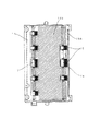
次に、本実施の形態における粘着シートの構成を図3、図4を用いて説明する。
【0036】
本実施の形態において、課題の項の搬送ローラ対Rに相当するシート搬送回転部材としてのローラは、第1レジストローラ4a,4bと、第2レジストローラ5及びその対向側のリードローラ6になる。これら2つの搬送ローラ対の従動回転部材としての従動コロにあたる第1レジストローラ4a,第2レジストローラ5には、当接部材(第1,第2当接部材)としてのスクレーパ18がローラの回転方向に対しカウンター方向で先端が当接するように設けられており、ローラ表面に付着したゴミ(異物)を掻き落とす構成になっている。
【0037】
粘着部材としての粘着シート19はこの2つの従動コロ(4a,5)を覆っている開閉カバー(カバー部材)下17の裏面のうち、図4に示す様に貼り付け可能な部分を覆って貼り付けられており、スクレーパ18で掻き落とされたゴミを開閉カバー(16(上部カバー部材),17(下部カバー部材))内に閉じ込める構成になっている。
【0038】
具体的には、開閉カバー下17の裏面に粘着シート19a、開閉カバー下17の側面に粘着シート19b、開閉カバー上16の裏面(第1レジストローラ4aの中央ローラの真上)に粘着シート19c、が貼られており、これにより原稿処理装置の開閉動作及び開閉カバー16,17の開閉動作時のショックで開閉カバー下17のコロ穴から溜まったゴミがシート搬送経路としての搬送パス内に落下するのを防止している。また、粘着シート19はスクレーパ18に設けられていてもよい。
【0039】
本実施の形態によれば、搬送ローラ対の従動コロ(4a,5)にスクレーパ18を当接させ、スクレーパ18またはスクレーパ18近傍に粘着シート19を設ける構成をとることにより、従動コロ(4a,5)を常にきれいな状態に保ち、更にスクレーパ18で掻き落とされてカバー内に溜まったゴミが原稿処理装置101や開閉カバー16,17の開閉動作で再び搬送パス内に入りこむことを防止することができる。
【0040】
これにより、画像読取装置102の読み取り位置eに搬送されるゴミの量を減らし、黒スジの発生を減少させると共に、低コストでありかつ簡易なメンテナンスで常に原稿処理装置内部をきれいな状態に保つ効果が得られる。
【0041】
さらに、粘着シート19は貼付部としての貼り付け面側の粘着力を弱く、異物付着部としてのゴミ付着面側の粘着力を強く設けられているため容易に剥がすことができ、サービスマンがメンテナンスする際の交換性を良くしている。
【0042】
本実施の形態においては、画像読取装置102の読み取り位置eに原稿を搬送するシート搬送回転部材について説明したが、これに限らず、画像形成装置や画像読取装置などに備えられるシート搬送装置に適用することができ、シートを搬送するシート搬送回転部材に付着した異物を確実に除去することができる。
【0043】
【発明の効果】
以上説明したように、本発明によれば、シート搬送回転部材を常にきれいな状態に保つことができ、さらに、従来のように異物がシート搬送経路内に入り込んでしまうことを防止することができるので、装置内部をきれいな状態に保つことができ、異物による画像品質の低下やシートの汚れを防止することが可能となる。
【0044】
また、前記粘着部材は、強い粘着力を有して異物を付着させる異物付着部と、該粘着部材が設けられる配設部に弱い力で貼付く貼付部と、を備えることにより、メンテナンス時における交換性の向上を図ることができる。
【図面の簡単な説明】
【図1】本実施の形態に係る画像読取装置の概略図である。
【図2】本実施の形態に係る原稿処理装置の概略断面図である。
【図3】本実施の形態に係る粘着シートの例を示した開閉カバーの概略側面図である。
【図4】本実施の形態に係る粘着シートの例を示した開閉カバー下の概略上視図である。
【符号の説明】
1 積載トレイ
2 ピックアップローラ
3a 給紙ローラ
3b 摩擦分離パッド
4a 第1レジストローラ(上)
4b 第1レジストローラ(下)
5 第2レジストローラ
6 リードローラ
7 リードコロI
8 プラテンガラス(小)
9 白色板
10 ジャンプ台
11 高さ基準部材
12 リードコロII
13a 排反ローラ(上)
13b 排反ローラ(下)
14 排紙トレイ
15 プラテンガラス(大)
16 開閉カバー上
17 開閉カバー下
18 スクレーパ
19 粘着シート
20 反転パス
101 原稿処理装置
102 画像読取装置
103 露光装置
104 ヒンジ部
A 原稿積載部
B 原稿給紙部
C 原稿搬送部
D 原稿排紙部
E 排紙積載部
S1 排反センサ[0001]
BACKGROUND OF THE INVENTION
The present invention relates to a sheet processing apparatus that reads an image of a document or forms an image on a sheet, such as a scanner, a copier, a printer, or a facsimile machine, and particularly, a sheet provided in these apparatuses. The present invention relates to a sheet conveying apparatus for conveying a sheet.
[0002]
[Prior art]
2. Description of the Related Art Conventionally, as this type of sheet processing apparatus, for example, an image reading apparatus is provided with an original processing apparatus that is an example of an automatic sheet conveying apparatus that can be opened and closed in order to automatically feed a document as a sheet to the image reading apparatus. There is. In the image reading apparatus, the document automatically fed by the document processing apparatus is exposed to read the image of the document.
[0003]
Here, as this exposure method, there is a method (hereinafter referred to as “fixed reading”) in which an exposure operation is performed by temporarily stopping the original after the original is conveyed on the platen glass by the original processing apparatus and then moving the exposure apparatus. There is a method of performing an exposure operation by fixing an exposure apparatus at an exposure reading position and moving an original on a platen glass at a predetermined speed (hereinafter referred to as “flow-reading”).
[0004]
Since this scanning can shorten the document stop time, there is an advantage that the document replacement speed can be increased, and this technique is used in many products.
[0005]
[Problems to be solved by the invention]
However, in the case of the prior art as described above, the following problems have occurred.
[0006]
While the document is being conveyed, dust such as toner dust or paper dust is generated due to the rubbing between the image surface of the document and the guide. When this dust adheres to the conveyance roller pair R, the dust accumulates on the driven roller, and the accumulated dust may fall into the conveyance path again due to sliding friction with the document and be conveyed along with the document.
[0007]
In addition, there is known a method of providing a scraper on the driven roller to prevent the above-mentioned dust adhesion, but the scraper has a cleaning effect on the surface of the driven roller, but the dust collected by the scraper is collected in the vicinity. The document processing apparatus may fall into the transport path again due to a shock of the opening / closing operation of the document processing apparatus or the opening / closing operation of the opening / closing cover, and may be transported together with the document.
[0008]
When these dusts are conveyed to the reading unit of the image reading device that performs the flow reading and the dust stays or adheres on the reading position of the platen glass, the exposure device is fixed in the image reading device that performs the flow reading, There is a problem that streaks occur in the document transport direction of an image that is recognized and output as a line at that position.
[0009]
The present invention has been made in order to solve the above-described problems of the prior art, and an object of the present invention is to provide a high-quality sheet conveying apparatus capable of preventing image quality deterioration and sheet contamination due to foreign matter and It is to provide a sheet processing apparatus.
[0010]
[Means for Solving the Problems]
In the present onset Akira In order to achieve the above object,
A first sheet transport rotating member that transports the sheet along the sheet transport path;
A second sheet conveying rotating member that is provided downstream of the first sheet conveying rotating member in the sheet conveying direction and conveys the sheet along the sheet conveying path;
An upper cover member, and a lower cover member disposed with a space with respect to the upper cover member, and an openable and closable cover,
With
From the space between the upper cover member and the lower cover member, a part of the first sheet transport rotating member and a part of the second sheet transport rotating member have holes formed in the lower cover member. A sheet conveying apparatus in which the first sheet conveying rotating member and the second sheet conveying rotating member are arranged so as to protrude into the sheet conveying path via
The sheet conveying apparatus is
A first abutment member for scraping off foreign matter adhering to the first sheet conveying rotary member in contact with said first sheet conveying rotary member,
A second abutting member that abuts on the second sheet conveying rotating member and scrapes off foreign matter adhering to the second sheet conveying rotating member;
An adhesive member for adhering foreign matter scraped off by the first contact member and the second contact member ;
Equipped with a,
The adhesive member, of the surface facing the space in the lower cover member, characterized that you have provided over between the second sheet conveying rotary member and the first sheet conveying rotary member.
[0014]
The adhesive member, it is also suitable with strong and adhesion have foreign matter adhering portion Ru is adhered foreign matter, and a sticking part sticking with a small force to the lower cover member PSA member is provided, the.
It is also preferable that the adhesive member is further provided in a region on the upstream side in the sheet conveyance direction with respect to the first sheet conveyance rotation member in a surface of the lower cover member facing the space.
It is also preferable that the adhesive member is further provided on a surface of the upper cover member that faces the space.
[0015]
The sheet conveying rotation member conveys a sheet to a predetermined position in the sheet conveying path,
Sheet stacking means for stacking sheets conveyed by the sheet conveying rotation member;
Sheet discharge stacking means for discharging and stacking the sheet transported to the predetermined position by the sheet transport rotating member;
It is also suitable to provide.
[0016]
In the sheet processing apparatus, the sheet conveying apparatus described above,
At least one of an image forming unit that forms an image on a sheet and an image reading unit that reads image information of the sheet;
It is characterized by providing.
[0017]
The predetermined position is preferably a reading position at which the image reading unit reads image information on a sheet.
[0018]
DETAILED DESCRIPTION OF THE INVENTION
Exemplary embodiments of the present invention will be described in detail below with reference to the drawings. However, the dimensions, materials, shapes, and relative arrangements of the components described in this embodiment should be appropriately changed according to the configuration of the apparatus to which the invention is applied and various conditions. It is not intended to limit the scope to the following embodiments.
[0019]
In the present embodiment, a document processing apparatus is taken as an example of a sheet (automatic) conveying apparatus provided in an image reading apparatus as a sheet processing apparatus, and FIG. 1 shows a schematic diagram of the document processing apparatus and the image reading apparatus.
[0020]
The
[0021]
Next, a schematic sectional view of a
[0022]
The document stacking unit A has a stacking tray 1 as a sheet stacking unit, and stacks documents on the surface of the stacking tray 1.
[0023]
In the document feeder B, the
[0024]
The
[0025]
In the document conveying section C, the document conveyed from the document feeding section B is fed with a lead roller 6 (drive rotation member, sheet conveyance rotation member), a second registration roller 5 (driven rotation member, second sheet conveyance rotation member), and a lead roller I7. The lead roller II12 conveys the platen glass (small) 8 and the
[0026]
In the document discharge section D, while the exposure operation is performed at the reading position e, the
[0027]
Next, a method for conveying a double-sided document in the present embodiment will be described.
[0028]
First, the originals stacked on the original stacking part A are separated one by one by the original feeding part B and conveyed to the original conveying part C.
[0029]
In the document conveying section C, the sheet is conveyed between the platen glass (small) 8 and the
[0030]
In the document discharge section D, after the document trailing edge passes through the discharge sensor S1, the
[0031]
The
[0032]
Due to the configuration of the
[0033]
Therefore, in the document discharge section D, after the trailing edge of the document passes through the discharge sensor S1, the
[0034]
The document that has passed through the document transport unit C is transported again to the document discharge unit D, nipped by the
[0035]
Next, the structure of the adhesive sheet in this Embodiment is demonstrated using FIG. 3, FIG.
[0036]
In the present embodiment, the rollers as sheet conveyance rotating members corresponding to the conveyance roller pair R in the problem section are the
[0037]
The
[0038]
Specifically, the pressure-
[0039]
According to the present embodiment, the
[0040]
As a result, the amount of dust conveyed to the reading position e of the
[0041]
Furthermore, since the
[0042]
In the present exemplary embodiment, the sheet conveying rotation member that conveys the document to the reading position e of the
[0043]
【The invention's effect】
As described above, according to the present invention, always sheet conveying rotary member can be kept clean, further, it is possible to prevent the foreign matter as in the prior art intrudes into the sheet transport path Therefore, the inside of the apparatus can be kept clean, and it is possible to prevent image quality deterioration and sheet contamination due to foreign matter.
[0044]
Further, the adhesive member has a strong adhesive force and the foreign matter adhering portion Ru deposited foreign matter have a sticking part rather sticking with a small force to the arrangement portion where the adhesive member is provided, by providing a maintenance It is possible to improve exchangeability in
[Brief description of the drawings]
FIG. 1 is a schematic diagram of an image reading apparatus according to an embodiment.
FIG. 2 is a schematic cross-sectional view of the document processing apparatus according to the present embodiment.
FIG. 3 is a schematic side view of an opening / closing cover showing an example of an adhesive sheet according to the present embodiment.
FIG. 4 is a schematic top view below an opening / closing cover showing an example of an adhesive sheet according to the present embodiment.
[Explanation of symbols]
DESCRIPTION OF SYMBOLS 1
4b First registration roller (bottom)
5
8 Platen glass (small)
9
13a Discharge roller (top)
13b Ejection roller (bottom)
14
16 Opening and closing
Claims (7)
前記第1シート搬送回転部材よりもシート搬送方向の下流側に設けられ、前記シート搬送経路に沿ってシートを搬送する第2シート搬送回転部材と、
上部カバー部材と、前記上部カバー部材に対して空間を隔てて配置された下部カバー部材とで構成され、開閉可能な開閉カバーと、
を備え、
前記上部カバー部材と前記下部カバー部材との間の前記空間から、前記第1シート搬送回転部材の一部および前記第2シート搬送回転部材の一部が、前記下部カバー部材に形成された穴を介して前記シート搬送経路内に突出するように、前記第1シート搬送回転部材および前記第2シート搬送回転部材が配置されたシート搬送装置であって、
前記シート搬送装置は、
前記第1シート搬送回転部材に当接して該第1シート搬送回転部材に付着した異物を掻き落とす第1当接部材と、
前記第2シート搬送回転部材に当接して該第2シート搬送回転部材に付着した異物を掻き落とす第2当接部材と、
前記第1当接部材および前記第2当接部材により掻き落とされた異物を付着させるための粘着部材と、
を備え、
前記粘着部材は、前記下部カバー部材における前記空間に対向する面のうち、前記第1シート搬送回転部材と前記第2シート搬送回転部材との間に亘って設けられていることを特徴とするシート搬送装置。A first sheet transport rotating member that transports the sheet along the sheet transport path;
A second sheet conveying rotating member that is provided downstream of the first sheet conveying rotating member in the sheet conveying direction and conveys the sheet along the sheet conveying path;
An upper cover member, and a lower cover member disposed with a space with respect to the upper cover member, and an openable and closable cover,
With
From the space between the upper cover member and the lower cover member, a part of the first sheet transport rotating member and a part of the second sheet transport rotating member have holes formed in the lower cover member. A sheet conveyance device in which the first sheet conveyance rotation member and the second sheet conveyance rotation member are arranged so as to protrude into the sheet conveyance path through
The sheet conveying apparatus is
A first abutment member for scraping off foreign matter adhering to the first sheet conveying rotary member in contact with said first sheet conveying rotary member,
A second abutting member that abuts on the second sheet conveying rotating member and scrapes off foreign matter adhering to the second sheet conveying rotating member;
An adhesive member for adhering foreign matter scraped off by the first contact member and the second contact member ;
Equipped with a,
The adhesive member, of the surface facing the space in the lower cover member, characterized that you have provided over between the first sheet conveying rotary member and the second sheet conveying rotary member sheet Conveying device.
強い粘着力を有して異物を付着させる異物付着部と、
該粘着部材が設けられる前記下部カバー部材に弱い力で貼り付く貼付部と、
を備えることを特徴とする請求項1に記載のシート搬送装置。The adhesive member is
And foreign matter adhesion portion Ru deposited foreign matter has a strong adhesive force,
An affixing part that adheres to the lower cover member provided with the adhesive member with a weak force;
The sheet conveying apparatus according to claim 1, further comprising:
前記第1及び第2シート搬送回転部材により搬送されるシートが積載されるシート積載手段と、
前記第1及び第2シート搬送回転部材により前記所定の位置へ搬送されたシートを排出して積載するシート排出積載手段と、
を備えることを特徴とする請求項1乃至4のいずれかに記載のシート搬送装置。It said first and second sheet conveying rotary member is adapted to convey the sheet to a predetermined position of the sheet conveying path,
A sheet stacking means the sheet is stacked to be transported by said first and second sheet conveying rotary member,
A sheet discharge stacking means for stacking and discharging the sheet that has been conveyed to the predetermined position by the first and second sheet conveying rotary member,
The sheet conveying apparatus according to any one of claims 1 to 4, further comprising:
シートに画像を形成する画像形成手段及びシートの画像情報を読取る画像読取手段のうち少なくともいずれか一方と、
を備えることを特徴とするシート処理装置。A sheet conveying device according to claim 5 ;
At least one of an image forming unit that forms an image on a sheet and an image reading unit that reads image information of the sheet;
A sheet processing apparatus comprising:
Priority Applications (1)
| Application Number | Priority Date | Filing Date | Title |
|---|---|---|---|
| JP2000327175A JP4366006B2 (en) | 2000-10-26 | 2000-10-26 | Sheet conveying apparatus and sheet processing apparatus |
Applications Claiming Priority (1)
| Application Number | Priority Date | Filing Date | Title |
|---|---|---|---|
| JP2000327175A JP4366006B2 (en) | 2000-10-26 | 2000-10-26 | Sheet conveying apparatus and sheet processing apparatus |
Publications (3)
| Publication Number | Publication Date |
|---|---|
| JP2002128306A JP2002128306A (en) | 2002-05-09 |
| JP2002128306A5 JP2002128306A5 (en) | 2007-12-13 |
| JP4366006B2 true JP4366006B2 (en) | 2009-11-18 |
Family
ID=18804251
Family Applications (1)
| Application Number | Title | Priority Date | Filing Date |
|---|---|---|---|
| JP2000327175A Expired - Fee Related JP4366006B2 (en) | 2000-10-26 | 2000-10-26 | Sheet conveying apparatus and sheet processing apparatus |
Country Status (1)
| Country | Link |
|---|---|
| JP (1) | JP4366006B2 (en) |
Families Citing this family (1)
| Publication number | Priority date | Publication date | Assignee | Title |
|---|---|---|---|---|
| JP7501073B2 (en) | 2020-04-23 | 2024-06-18 | セイコーエプソン株式会社 | Recording device |
-
2000
- 2000-10-26 JP JP2000327175A patent/JP4366006B2/en not_active Expired - Fee Related
Also Published As
| Publication number | Publication date |
|---|---|
| JP2002128306A (en) | 2002-05-09 |
Similar Documents
| Publication | Publication Date | Title |
|---|---|---|
| JP2004048184A (en) | Image reader | |
| JP4366006B2 (en) | Sheet conveying apparatus and sheet processing apparatus | |
| JP3571288B2 (en) | Automatic document feeder having image reading means and image reading apparatus | |
| JP4413790B2 (en) | Image reading apparatus and image forming apparatus | |
| JP3949474B2 (en) | Sheet conveying apparatus and image forming apparatus | |
| JP4597408B2 (en) | Automatic document feeder and image reading apparatus | |
| JP5219629B2 (en) | Sheet conveying apparatus and image forming apparatus | |
| JP4011394B2 (en) | Automatic document feeder | |
| JP2000151913A (en) | Image reader | |
| JP2000029253A (en) | Image forming device | |
| JP2014047067A (en) | Document feeding device, image reading apparatus, and image forming apparatus | |
| JP4416717B2 (en) | Document reader | |
| JP2001309118A (en) | Original carrying device | |
| JP2010095388A (en) | Image reading apparatus and image forming apparatus | |
| JP4186948B2 (en) | Image forming apparatus | |
| JP2005343668A (en) | Image reading device | |
| JP6579437B2 (en) | Document conveying apparatus and image forming apparatus | |
| JP5274108B2 (en) | Sheet conveying apparatus and image forming apparatus | |
| JP3638496B2 (en) | Paper transport device | |
| JP3727237B2 (en) | Image reading device | |
| JP2002218166A (en) | Image reader | |
| JP2002145475A (en) | Sheet feeding device and image reading device having the paper feeding device and image forming device | |
| JP4526347B2 (en) | Automatic document feeder and image forming apparatus | |
| JP2009105830A (en) | Image reader and image forming apparatus | |
| JP2002354191A (en) | Image reader and image forming device |
Legal Events
| Date | Code | Title | Description |
|---|---|---|---|
| A521 | Written amendment |
Free format text: JAPANESE INTERMEDIATE CODE: A523 Effective date: 20071025 |
|
| A621 | Written request for application examination |
Free format text: JAPANESE INTERMEDIATE CODE: A621 Effective date: 20071025 |
|
| A977 | Report on retrieval |
Free format text: JAPANESE INTERMEDIATE CODE: A971007 Effective date: 20090513 |
|
| A131 | Notification of reasons for refusal |
Free format text: JAPANESE INTERMEDIATE CODE: A131 Effective date: 20090519 |
|
| A521 | Written amendment |
Free format text: JAPANESE INTERMEDIATE CODE: A523 Effective date: 20090721 |
|
| TRDD | Decision of grant or rejection written | ||
| A01 | Written decision to grant a patent or to grant a registration (utility model) |
Free format text: JAPANESE INTERMEDIATE CODE: A01 Effective date: 20090818 |
|
| A01 | Written decision to grant a patent or to grant a registration (utility model) |
Free format text: JAPANESE INTERMEDIATE CODE: A01 |
|
| A61 | First payment of annual fees (during grant procedure) |
Free format text: JAPANESE INTERMEDIATE CODE: A61 Effective date: 20090824 |
|
| FPAY | Renewal fee payment (event date is renewal date of database) |
Free format text: PAYMENT UNTIL: 20120828 Year of fee payment: 3 |
|
| R150 | Certificate of patent or registration of utility model |
Ref document number: 4366006 Country of ref document: JP Free format text: JAPANESE INTERMEDIATE CODE: R150 Free format text: JAPANESE INTERMEDIATE CODE: R150 |
|
| FPAY | Renewal fee payment (event date is renewal date of database) |
Free format text: PAYMENT UNTIL: 20120828 Year of fee payment: 3 |
|
| FPAY | Renewal fee payment (event date is renewal date of database) |
Free format text: PAYMENT UNTIL: 20130828 Year of fee payment: 4 |
|
| LAPS | Cancellation because of no payment of annual fees |