JP4365954B2 - Belt and image forming apparatus having the same - Google Patents
Belt and image forming apparatus having the same Download PDFInfo
- Publication number
- JP4365954B2 JP4365954B2 JP30167599A JP30167599A JP4365954B2 JP 4365954 B2 JP4365954 B2 JP 4365954B2 JP 30167599 A JP30167599 A JP 30167599A JP 30167599 A JP30167599 A JP 30167599A JP 4365954 B2 JP4365954 B2 JP 4365954B2
- Authority
- JP
- Japan
- Prior art keywords
- belt
- foam
- meandering prevention
- transfer
- prevention member
- Prior art date
- Legal status (The legal status is an assumption and is not a legal conclusion. Google has not performed a legal analysis and makes no representation as to the accuracy of the status listed.)
- Expired - Fee Related
Links
Images


Classifications
-
- G—PHYSICS
- G03—PHOTOGRAPHY; CINEMATOGRAPHY; ANALOGOUS TECHNIQUES USING WAVES OTHER THAN OPTICAL WAVES; ELECTROGRAPHY; HOLOGRAPHY
- G03G—ELECTROGRAPHY; ELECTROPHOTOGRAPHY; MAGNETOGRAPHY
- G03G15/00—Apparatus for electrographic processes using a charge pattern
- G03G15/75—Details relating to xerographic drum, band or plate, e.g. replacing, testing
- G03G15/754—Details relating to xerographic drum, band or plate, e.g. replacing, testing relating to band, e.g. tensioning
- G03G15/755—Details relating to xerographic drum, band or plate, e.g. replacing, testing relating to band, e.g. tensioning for maintaining the lateral alignment of the band
-
- G—PHYSICS
- G03—PHOTOGRAPHY; CINEMATOGRAPHY; ANALOGOUS TECHNIQUES USING WAVES OTHER THAN OPTICAL WAVES; ELECTROGRAPHY; HOLOGRAPHY
- G03G—ELECTROGRAPHY; ELECTROPHOTOGRAPHY; MAGNETOGRAPHY
- G03G15/00—Apparatus for electrographic processes using a charge pattern
- G03G15/14—Apparatus for electrographic processes using a charge pattern for transferring a pattern to a second base
- G03G15/16—Apparatus for electrographic processes using a charge pattern for transferring a pattern to a second base of a toner pattern, e.g. a powder pattern, e.g. magnetic transfer
- G03G15/1605—Apparatus for electrographic processes using a charge pattern for transferring a pattern to a second base of a toner pattern, e.g. a powder pattern, e.g. magnetic transfer using at least one intermediate support
- G03G15/1615—Apparatus for electrographic processes using a charge pattern for transferring a pattern to a second base of a toner pattern, e.g. a powder pattern, e.g. magnetic transfer using at least one intermediate support relating to the driving mechanism for the intermediate support, e.g. gears, couplings, belt tensioning
-
- G—PHYSICS
- G03—PHOTOGRAPHY; CINEMATOGRAPHY; ANALOGOUS TECHNIQUES USING WAVES OTHER THAN OPTICAL WAVES; ELECTROGRAPHY; HOLOGRAPHY
- G03G—ELECTROGRAPHY; ELECTROPHOTOGRAPHY; MAGNETOGRAPHY
- G03G2215/00—Apparatus for electrophotographic processes
- G03G2215/00135—Handling of parts of the apparatus
- G03G2215/00139—Belt
- G03G2215/00143—Meandering prevention
- G03G2215/00151—Meandering prevention using edge limitations
-
- G—PHYSICS
- G03—PHOTOGRAPHY; CINEMATOGRAPHY; ANALOGOUS TECHNIQUES USING WAVES OTHER THAN OPTICAL WAVES; ELECTROGRAPHY; HOLOGRAPHY
- G03G—ELECTROGRAPHY; ELECTROPHOTOGRAPHY; MAGNETOGRAPHY
- G03G2215/00—Apparatus for electrophotographic processes
- G03G2215/01—Apparatus for electrophotographic processes for producing multicoloured copies
- G03G2215/0103—Plural electrographic recording members
- G03G2215/0119—Linear arrangement adjacent plural transfer points
Landscapes
- Physics & Mathematics (AREA)
- General Physics & Mathematics (AREA)
- Electrostatic Charge, Transfer And Separation In Electrography (AREA)
- Delivering By Means Of Belts And Rollers (AREA)
- Fixing For Electrophotography (AREA)
- Discharging, Photosensitive Material Shape In Electrophotography (AREA)
- Structure Of Belt Conveyors (AREA)
Description
【0001】
【発明の属する技術分野】
本発明は、ベルト及びこれを備える画像形成装置に関し、特に無端状のベルトの内周面に設けられた蛇行防止部材に関する。
【0002】
【従来の技術】
従来の電子写真装置等の画像形成装置においては、ベルト状感光体、中間転写ベルト、転写ベルト、紙搬送ベルト、定着ベルト等としてエンドレスベルトが使用されている。
【0003】
ここで、このようなエンドレスベルトは、一般に2本以上のローラにより支持され、任意の張力を与えられながら回転駆動されているが、支持するローラの真直度あるいは真円度、各々のローラの軸線の平行度、エンドレスベルトそのものの真円度等に僅かな誤差やばらつきがあるため、回転駆動中に左右に蛇行する場合がある。そして、このようなエンドレスベルトを精度が要求されるフルカラー電子写真装置等の転写ベルトに用いた場合、この転写ベルトの蛇行により、転写ベルト上での色重ね時に各色の作像位置がずれ、色ズレを生じてしまう。
【0004】
そこで、このような蛇行を防止するため、転写ベルトの内周面に蛇行防止部材を全周にわたって設けると共に、転写ベルトが張架されるローラに溝を設け、この溝に蛇行防止部材を係止させながらローラを回転させることにより、転写ベルトを蛇行させることなくスムーズに走行させることができ、これにより色ズレのない良好な画像の形成が可能となる。
【0005】
【発明が解決しようとする課題】
ところが、この構成の転写ベルトでは、蛇行防止部材がローラ等で変形することによる応力により転写ベルトから蛇行防止部材が剥離したり、場合によっては転写ベルトに亀裂を生じることがあった。
【0006】
このため、例えば特開平08−099706号公報のようにベルト補強基材にアクリル発泡体を用い、その上に硬度を規定したポリウレタンシートを粘着することにより、蛇行防止効果とベルトヘの応力緩和効果を奏するようにしたものがある。
【0007】
しかし、このような構成の場合、蛇行防止部材の厚みの大部分を非発泡体が占めるため、ベルト屈曲部で蛇行防止部材が大きく変形し、多大な応力を受けることから、長期間使用した場合、蛇行防止部材が剥離することがある。
【0008】
そして、この現象は、特に転写ベルトを張架しているローラの直径が小さく、転写ベルトのローラに対する巻付角が大きい場合に顕著であった。つまり、転写ベルトの寿命を満たすためには転写ベルトを張架しているローラの直径を太くし、転写ベルトのローラヘの巻付角を小さくする、つまりローラを多軸にする必要があり、このことは画像形成装置の小型化の大きな障壁となる。
【0009】
そこで、本発明は、このような現状に鑑みてなされたものであり、耐久寿命の長いベルト及びこれを備える画像形成装置を提供することを目的とするものである。
【0010】
【課題を解決するための手段】
本発明は、無端状のベルト本体と、前記ベルト本体の内周面に設けられている蛇行防止部材を有し、前記ベルト本体は張架部材に張架され、前記ベルト本体と前記蛇行防止部材は移動可能であり、前記蛇行防止部材が前記張架部材に接触して前記ベルト本体及び前記蛇行防止部材の移動方向に直交する方向の移動を規制するベルトにおいて、前記蛇行防止部材は発泡体であり、前記蛇行防止部材の前記ベルト本体と接合する面及び前記張架部材と接する面に前記発泡体よりも空隙率が低い割合で空隙を有する層が形成されており、前記蛇行防止部材は前記ベルトの移動方向と垂直な方向の断面形状が正方形又は長方形であり、前記正方形又は長方形の4辺全てに前記発泡体よりも空隙率が低い割合で空隙を有する層が形成されており、前記発泡体の空隙率が20%以上80%以下であり、前記発泡体よりも空隙率が低い割合で空隙を有する層の空隙率が20%未満であることを特徴とするものである。
【0012】
また本発明は、前記蛇行防止部材は、前記張架部材の側端によって前記ベルト本体及び前記蛇行防止部材の移動方向に直交する方向の移動が規制されることを特徴とするものである。
【0013】
また本発明は、前記発泡体の平均発泡径が10μm以上300μm以下であることを特徴とするものである。
【0017】
また本発明は、前記発泡体よりも空隙率が低い割合で空隙を有する層の厚みが100μm以下であることを特徴とするものである。
【0018】
また本発明は、前記ベルト本体は、つなぎ目を有さないシームレスベルトであることを特徴とするものである。
【0019】
また本発明は、トナー像を担持する像担持体と、前記像担持体上に形成されたトナー像が転写される中間転写ベルトとを備え、前記中間転写ベルト上のトナー像は転写材に転写される画像形成装置において、前記中間転写ベルトは、上記のいずれかに記載のベルトであることを特徴とするものである。
【0020】
また本発明は、トナー像を担持する像担持体と、転写材を担持する転写搬送ベルトと、前記像担持体上のトナー像を前記転写搬送ベルト上の転写材へ転写する画像形成装置において、前記転写搬送ベルトは、上記のいずれかに記載のベルトであることを特徴とするものである。
【0021】
また本発明のように構成することにより、外周面に像担持体に形成されたトナー像が転写される無端状のベルト本体の内周面の少なくとも一側部に設けられ、ローラに形成された係止溝に係止される蛇行防止部材を発泡体により形成することにより、蛇行防止部材のベルト本体からの剥離及びベルト本体の破損を防止するようにする。
【0022】
【発明の実施の形態】
以下、本発明の実施の形態について図面を用いて詳細に説明する。
【0023】
図1は、本発明の実施の形態に係るベルトの一例である中間転写ベルトを用いるレーザーカラープリンタ(画像形成装置)の概略構成を示す図である。
【0024】
同図において、1は第1の画像担持体としてのドラム状の電子写真感光体(以下、感光ドラムという)であり、矢印の方向に所定の周速度(プロセススピード)で回転駆動されるようになっている。
【0025】
また、2は感光ドラム1の表面を所定の極性、電位に一様に帯電処理するコロナチャージャ、41〜44は不図示の画像露光手段によって露光3を受けることにより感光ドラム上に形成された静電潜像をM(マゼンタ)、C(シアン)、Y(イエロー)、B(ブラック)のトナーによりそれぞれ現像する現像器である。なお、画像露光手段としては、カラー原稿の色分解・結像露光光学系、画像情報の時系列電気デジタル画素信号に対応して変調されたレーザービームを出力するレーザースキャナによる走査露光光学系等を使用する。
【0026】
また、6は中間転写ベルト、8は中間転写ベルト6を感光ドラム1に押し付けながら回転する一次転写ローラであり、感光ドラム1上に形成担持されたトナー画像は、中間転写ベルト6が感光ドラム1に圧接しながら通過する過程で、電源15から一次転写ローラ8に印加されるトナーとは逆の極性の一次転写バイアスにより形成される電界と圧力とにより、中間転写ベルト6の外周面上に転写されるようになっている。
【0027】
なお、この中間転写ベルト6は、駆動ローラ9、テンションローラ10、二次転写対向ローラ11及び一次転写ローラ8に張架されると共に、駆動ローラ9により矢印の方向に所定の周速度をもって回転駆動されるようになっている。
【0028】
また、12は中間転写ベルト6に当接する二次転写ローラであり、中間転写ベルト6上に転写されたフルカラー画像は、給紙カセット14から所定のタイミングでピックアップローラ13a等により給送された第2の担持体である転写材13が、中間転写ベルト6と二次転写ローラ12との当接ニップを通過する際、バイアス電源16から二次転写ローラ12に印加される二次転写バイアスによって転写材13に転写されるようになっている。
【0029】
また、17は転写されたトナー画像を転写材13に加熱定着する定着器、7は転写材13への画像転写終了後、中間転写ベルト6上の転写残トナーをクリーニングする中間転写ベルトクリーニング部材、5は感光ドラム1のクリーニング部材である。
【0030】
次に、このような構成の画像形成装置の画像形成動作について説明する。
【0031】
画像形成の際は、まず感光ドラム1の表面を、感光ドラム1の回転過程においてコロナチャージャ2により所定の極性、電位に一様に帯電処理する。次に、不図示の画像露光手段からの露光3により感光ドラム1の表面に目的のカラー画像の第1の色成分(例えばマゼンタ成分像)に対応した静電潜像を形成する。
【0032】
次に、その静電潜像を第1の現像器41(マゼンタ現像器)によって現像し、この後、この感光ドラム1上に形成担持された第1色のマゼンタトナー画像を、矢印の方向に所定の周速度をもって感光ドラム1に圧接しながら回転駆動している中間転写ベルト6の外周面上に、電源15から一次転写ローラ8に印加される一次転写バイアスによって一次転写する。
【0033】
以下、同様に第2色のシアントナー画像、第3色のイエロートナー画像及び第4色のブラックトナー画像を順次中間転写ベルト6上に重畳転写し、これにより目的のフルカラー画像を形成する。なお、この一次転写行程においては、二次転写ローラ12及び中間転写ベルトクリーニング部材7は中間転写ベルト6から離間している。
【0034】
次に、中間転写ベルト6上に重畳転写されたフルカラー画像を、所定のタイミングで給紙カセット14から給送され、中間転写ベルト6と二次転写ローラ12との当接ニップを通過する転写材13に、このときには既に中間転写ベルト6に当接した状態となっている二次転写ローラ12にバイアス電源16から印加される二次転写バイアスによって転写する。
【0035】
そして、このようにトナー画像が二次転写された転写材13を、定着器17へ導入し、この定着器17においてトナー画像を転写材13に加熱定着する。なお、転写材13への画像転写終了後、中間転写ベルト6上の転写残トナーは、このときには既に中間転写ベルト6に当接した状態となっている中間転写ベルトクリーニング部材7により除去される。
【0036】
一方、図2は本発明の実施の形態に係るベルトの一例である転写搬送ベルトを用いる画像形成装置の概略構成を示す図である。なお、同図において、図1と同一符号は、同一又は相当部分を示している。また、この画像形成装置は、複数色(例えばイエロー、マゼンタ、シアン及びブラック)の作像ステーションを配列したタンデム方式のレーザーカラープリンタである。
【0037】
同図において、20Y、20M、20C、20Kは第1〜第4作像ステーションであり、これら各作像ステーション20Y,20M,20C,20Kは、それぞれ矢印の方向に所定の周速度(プロセススピード)で回転駆動される感光ドラム1Y,1M,1C,1Kと、感光ドラム1Y,1M,1C,1Kの表面を所定の極性、電位に一様に帯電処理する一次帯電ローラ2Y,2M,2C,2Kと、不図示の画像露光手段によって露光3Y,3M,3C,3Kを受けることにより感光ドラム上に形成された静電潜像をM、C、Y、Bのトナーによりそれぞれ現像する現像器4Y,4M,4C,4Kとを備えている。
【0038】
また、61は駆動ローラ9と従動ローラ91に張架され、駆動ローラ9により矢印の方向に所定の周速度をもって回転駆動される転写搬送ベルト、8Y、8M、8C、8Kは転写シートであり、感光ドラム1Y,1M,1C,1K上に形成担持されたトナー画像は、転写材13が感光ドラム1Y,1M,1C,1Kと転写搬送ベルト61とのニップ部を通過する過程で、バイアス電源15Y,15M,15C,15Kから転写シート8Y,8M,8C,8Kに印加される転写バイアスにより転写材13上に転写されるようになっている。
【0039】
また、18は転写搬送ベルト61に転写材13を吸着させるため吸着ローラ18に所定の吸着バイアスを印加するための吸着ローラであり、19は転写材13を転写搬送ベルト61から分離するための分離バイアスを印加する分離チャージャである。
【0040】
次に、このような構成の画像形成装置の画像形成動作について説明する。
【0041】
画像形成の際は、まず帯電行程として第1作像ステーション20Yの感光ドラム1Yの表面を、感光ドラム1Yの回転過程において一次帯電ローラ2Yにより所定の極性、電位に一様に帯電処理する。次に、露光行程として不図示の画像露光手段からの露光3Yにより感光ドラム1Yの表面に目的のカラー画像の第1の色成分(イエロー)に対応した静電潜像を形成する。
【0042】
次に、現像行程として静電潜像を第1の現像器4Y(イエロー現像器)により現像する。この後、転写行程として、この感光ドラム1Y上に形成担持された第1色のイエロートナー画像を、所定のタイミングで給紙カセット14から給送された後、駆動ローラ9により矢印の方向に所定の周速度をもって回転駆動している転写搬送ベルト61に担持されて移動する転写材13が、転写搬送ベルト61と感光ドラム1Yとの当接ニップを通過する際、この転写材13に、バイアス電源15Yから転写シート8Yに印加される転写バイアスによって静電的に転写する。なお、要すれば、転写搬送ベルト61に転写材13を吸着させるために吸着ローラ18に所定の吸着バイアスを印加する。
【0043】
次に、クリーニング行程として感光ドラム1Yから転写材13上に転写されなかった残トナーは感光ドラムクリーナ5Yにより除去される。以後、上記の帯電、露光、現像、転写及びクリーニングの各作像行程を繰り返す。
【0044】
さらに、第2〜第4作像ステーション20M,20C,20Kにおいても、所定のタイミングで第1作像ステーション20Yと同様の作像行程を経ることにより転写材13上にイエロー、マゼンタ、シアン及びブラックトナーを重畳転写し、目的とするフルカラー画像を形成する。
【0045】
その後、トナー画像が転写された転写材13を、転写搬送ベルト61から分離した後、定着器17へ導入し、この定着器17においてトナー画像を転写材13に加熱定着する。さらに、転写材13への画像転写終了後、転写搬送ベルト61上の紙粉、トナー等をベルトクリーニング部材71により除去する。なお、転写材13を転写搬送ベルト61から分離する際、分離チャージャ19を使用することもある。
【0046】
ところで、蛇行に関して精度を要求されるベルトである中間転写ベルト6及び転写搬送ベルト61(以下、中間転写ベルト6等という)は、図3の(a)〜(c)に示すように外周面にトナー像が転写される無端状のベルト本体6a,61aと、このベルト本体6a,61aの内周面の片端部あるいは両端部に設けられた蛇行防止部材6b,61bとを有している。
【0047】
ところが、中間転写ベルト6等は、2本以上のローラ(図1及び図2参照)に張架されて回転駆動されるため、単に蛇行防止部材6b,61bを配設しただけでは、既述したように蛇行防止部材6b,61bがローラ部で変形することによる応力によりベルト本体6a,61aから蛇行防止部材6b,61bが剥離したり、場合によってはベルト本体6a,61aに亀裂を生じる。
【0048】
そこで、本実施の形態において、この蛇行防止部材6b,61bとして発泡体を用いるようにしている。そして、このように発泡体を用いることにより、蛇行防止部材6b,61bがローラ部等での変形に追従することができるようになる。これにより、蛇行防止部材6b,61bに加わる応力を軽減することができ、蛇行防止部材6b,61bのベルト本体6a,61aからの剥離及びベルト本体6a,61aの破損を防止することが可能となる。
【0049】
ここで、発泡体の平均発泡径は10μm以上300μm以下であることが好ましい。なお、平均発泡径が10μm未満の場合には蛇行防止部材6b,61bが変形に対して追従し難くなることからベルト本体6a,61aからの剥離が発生し易くなり、平均発泡径が300μmを超える場合には蛇行防止部材6b,61bの真直度が低くなることから蛇行防止効果が低下する場合がある。
【0050】
また、発泡体の空隙率は20%以上80%以下であることが好ましい。なお、空隙率が20%未満である場合には、蛇行防止部材6b,61bが変形に対して追従し難くなることからベルト本体6a,61aからの剥離が発生し易くなり、80%を超える場合には蛇行防止部材6b,61bの剛性が低下してしまい蛇行防止効果が低下する場合がある。
【0051】
さらに、蛇行防止部材6b,61bとベルト本体6a,61aとが接合する面及び蛇行防止部材6b,61bとローラ部材とが接する面の少なくとも一方には、即ち発泡体のベルト本体6a,61aと接合する面及びローラと接する面の少なくとも一方には、図3の(b)に示すように空隙率が他の部分よりも明らかに低い表層であるスキン層6c,61cを有していることが好ましい。
【0052】
そして、このようなスキン層6c,61cを有することにより、蛇行防止部材6b,61bとベルト本体6a,61aを接合(接着、粘着等)する場合の接合強度を高めることが可能となる。また、蛇行防止部材6b,61bとローラとの摺動性が向上し、蛇行防止効果が高くなる。
【0053】
ここで、このような効果はスキン層6c,61cの空隙率が20%未満である場合に著しく発揮される。また、スキン層6c,61cの厚みは100μm以下であることが好ましい。なお、スキン層が100μmを越えると、蛇行防止部材6b,61bの柔軟性が低下し、変形に対して追従し難くなることからベルト本体6a,61aからの剥離が発生し易くなる。
【0054】
また、蛇行防止部材6b,61bを有するベルト本体6a,61aは、つなぎめを有さないシームレスベルトであることが好ましい。そして、このようにつなぎめを有さないことにより膜厚ムラを小さくすることが可能となり、ローラ部での屈曲によるベルト本体6a,61aヘの応力の集中を抑えられることから、ベルト本体6a,61aの寿命を更に長くすることができる。
【0055】
ところで、蛇行防止部材6b,61bを構成する発泡体の材質としては特に限定されるものではなく公知の発泡体が使用できるが、圧縮永久歪みが小さく各種の接着剤、粘着剤でのベルト本体6a,61aヘの接合が可能であるという点から、ウレタン系発泡体、アクリル系発泡体が好ましい。
【0056】
また、蛇行防止部材6b,61bの断面形状は、既述した図3の(c)に示すように中間転写ベルト6等を張架するローラRの外周面に形成された蛇行防止用の溝R1に係止されるような断面形状であるが、一般に加工の容易さ等の理由から断面形状は正方形又は長方形のものが使用される。具体的には、幅1〜5mm、厚さ0.3〜0.5mmの正方形又は長方形の断面形状のものが好ましいが、この範囲に限定されるものではない。
【0057】
なお、本実施の形態においては、蛇行防止部材6b,61bをローラRの外周面に形成された蛇行防止用の溝R1に係止する場合について述べているが、蛇行防止部材6b,61bを図3の(d)に示すようにローラRの側端に係止するようにしてもよい。そして、このような場合でも、蛇行防止部材6b,61bの断面形状は上記のようにするのが好ましい。
【0058】
一方、可撓性を有するベルト本体6a,61aとしては、ベルト形状であればフィルム状のものや、メッシュ状のもの等、特に何ら限定されるものではない。また、その材質としては、熱硬化性樹脂、熱可塑性樹脂、金属及びゴム等、種々の材料からなるものを挙げることができるが、特に成型のし易さ、コスト等の面から、熱可塑性樹脂からなるものが好ましい。
【0059】
具体的には、ポリエチレン(高密度、中密度、低密度、直鎖状低密度等)、ポリプロピレン、ポリスチレン、エチレン−ビニルアルコール共重合体(EVOH)、ポリカボネート、ポリアミド、ポリアセタール、ポリアリレート、ポリフェニレンエーテル、変性ポリフェニレンエーテル、ポリイミド、液晶性ポリマー、ポリサルホン、ポリエーテルサルフォン、ポリフェニレンサルファイト、ポリビスアミドトリアゾール、ポリエーテルイミド、ポリアミドイミド、ポリエーテルエーテルケトン、脂肪族ポリケトン、ポリメチルペンテン、ポリブチレンテレフタレート、ポリエチレンテレフタレート、ポリエチレンナフタレート、ポリフッ化ビニル、ポリフッ化ビニリデン(PVdF)、クロロトリフルオロエチレン、エチレン四フッ化エチレン共重合体(ETFE)、ヘキサフルオロプロピレン、パーフルオロアルキルビニルエーテル共重合体、メタクリル樹脂、その他各種共重合体などから選ばれる1種類あるいは2種類以上を使用することができる。
【0060】
特に、これらに限定されるものではないが、ベルトの機械特性、成型性等を考慮してポリカーボネート、ポリフッ化ビニリデン(PVdF)、ポリサルホン、ポリイミド、ポリフェニレンサルファイド、ポリアリレート、エチレン四フッ化エチレン共重合体(ETFE)が好ましい。
【0061】
また、これらの樹脂に導電性を付与する目的で、例えばアセチレンブラック、ファーネスブラック、チャンネルブラック等のカーボンブラック、酸化チタン、チタン酸カリウム、酸化錫、リチウム塩、四級アンモニウム塩等の各種導電剤を添加しても良い。
【0062】
更に、タルク、マイカ、炭酸カルシウム等の充填剤、水酸化マグネシウム、三酸化アンチモン等の難燃剤、酸化防止剤(フェノール系、硫黄系等)等の添加剤を添加しても何ら差し支えない。もちろん、添加剤は上記物質に限定されるものではなく、その他任意の添加剤を使用することができる。
【0063】
ここで、上記樹脂に添加剤を添加する方法として、予備混合を行った後、一軸押出機、二軸押出機、バンバリーミキサー、ローラ、ニーダー等の公知の混練機を用いて混練、分散する方法が挙げられる。通常は、押出機等で各成分を各々に混練してベレット状のコンパウンドにした後に成型加工するが、特殊な場合は各成分を直接成形機に供給し、成形機で本組成物を混練しながら成形することもできる。
【0064】
一方、ベルト本体6a,61aの製造方法としては、遠心成形法、連続溶融押出成形法、射出成形法あるいはブロー成形法、インフレーションフィルム成形法等公知の方法を採用することができるが、連続溶融押出成型法あるいはインフレーション成型法が低コストで製造できることから好ましい。なお、この様にして成型されたエンドレスベルトは、延伸等の操作を行っても良い。
【0065】
ここで、ベルト本体6a,61aの厚みは、50μm以上1000μm以下が好ましく、100μm以上700μm以下が更に好ましい。なお、50μm未満になるとベルト本体6a,61aが伸び易くなり、また、1000μmを越えると柔軟な変形が困難になるため、小径ローラによる均一な速度の駆動ができず、装置の大型化の問題が生ずる。
【0066】
さらに、ベルト本体6a,61aは単層からなるものでもよいし、複数の層により構成されるものでもよい。また、複数の層からなるベルト本体6a,61aを得る場合、予め複数の層で形成した熱可塑性樹脂部材を多層ダイスからの押出しによって得てもよいし、単層の熱可塑性樹脂部材から単層の円筒状フィルムを得て、その後、この単層エンドレスベルトの表面あるいは裏面に、例えば塗料等のスプレー、ディッピング等により新たな層を設けることにより複数の層からなるベルト本体6a,61aを得るようにしてもよい。
【0067】
一方、蛇行防止部材6b,61bとベルト本体6a,61aの接合方法は特に限定されるものではなく公知の接合(接着、粘着)方法により接合することができるが、取り扱いのし易さ、接合強度からアクリル系粘着剤を有する両面テープを使用するのが好ましい。
【0068】
また、補強あるいはベルト本体6a,61aと蛇行防止部材6b,61bの接合強度の向上を目的として、ベルト本体6a,61aの端部に不図示の帯状の部材を設けてもよい。なお、この帯状部材の材質としては各種材料を使用することができるが、ベルトの補強効果、取り扱いのし易さ等からPET(ポリエチレンテレフタレート)テープが好ましい。
【0069】
さらに、ベルト本体6a,61aと蛇行防止部材6b,61bの接合強度の向上を目的として蛇行防止部材6b,61bとベルト本体6a,61aの接合面にコロナ処理等の各種表面処理を施すことも可能である。
【0070】
次に、発泡体の平均発泡径及び空隙率の測定方法について説明する。
【0071】
測定を行う際、まず蛇行防止部材6b,61bを任意の箇所で鋭利な刃物(かみそり等)を用いて、発泡体(セル)をつぶさないように切断する。
【0072】
次に、顕微鏡(光学顕微鏡、走査電子顆微鏡等)を使用して拡大し、任意の計測範囲S(μm2 )当たりのセル数Nをカウントし、それぞれのセルの直径R(μm)を測定する。ここで、セルの形状が不定形である場合にはセルの外周を測定し、実測した外局と同等の外周を有する円とセルを仮定してセルの直径とする。拡大倍率や計測範囲は、セルの大きさ等を考慮して測定し易い条件を選ぶことができるが、カウントするセル数は50個以上となるように計測範囲を設定する。
【0073】
【数式1】

【0074】
【数式2】
【0075】
次に、本実施の形態の実施例について説明する。
【0076】
【実施例1】
<エンドレスベルトの作製>
3種類の材料を下記のように配合する。
【0077】
ポリカーボネート樹脂 100 重量部
カーボンブラック 15 重量部
酸化防止剤 0.5 重量部
上記のように配合された3種類の材料を2軸の押し出し混練機で混練せしめ、カーボンブラック等添加剤を充分にバインダー中に均一分散させ、成型用原料を得た。更にこれを1〜2mmの粒径の混練物とした後、一軸押し出し機のホッパーヘ投入し、温度を270〜290℃の範囲に調節して押し出すことにより、溶融体とした。
【0078】
次に、この溶融体を直径100mm、ダイギャップ900μmの円筒状単層用押し出しダイスに導いた後、空気導入路より空気を吹き込んで拡大膨張させ、最終的な形状寸法として直径140mm、厚み150μmとした。更にベルト巾250mmで切断し、シームレスベルトを得た。
【0079】
一方、補強部材として、ポリエチレンテレフタレート樹脂からなる補強テープを用いて、シームレスベルトの内周面の両端部に貼着して、内周面に補強部材を有するシームレスベルトを得た。
<エンドレスベルトヘの蛇行防止部材の接合>
次に、このようにして得られたシームレスベルトの補強部材内周面上に厚さ2mm、幅3mmの断面形状が長方形で、断面の4辺にスキン層を有するポリウレタン発泡体をアクリル系粘着剤を有する両面テープで貼着して蛇行防止部材を有するエンドレスベルトを得た。ここで、スキン層の厚みは約3μmでスキン層の空隙率は10%であった。また、発泡体の平均発泡径は50μmで発泡体の空隙率は50%であった。
【0080】
そして、このようにして得られた蛇行防止部材を有するエンドレスベルトを図1の構成のカラーレーザープリンタの中間転写ベルト6として組込み、中間転写ベルト6の4万回転に相当するフルカラー1万枚の耐久試験を行った。その結果、蛇行防止部材の剥離及びベルト端部に割れや欠けなどの不具合は発生せず、十分な耐久性を有していた。また、色ズレ量も平均で約50μmと良好であった。
【0081】
なお、色ズレ量の平均値は、図4に示すようなライン画像(ライン幅200μm以下の画像)を出力して、一番ズレ量が大きい2色間の値を100サンプル測定後、平均することにより求めた。
【0082】
更に、同様にして作製した蛇行防止部材を有する未耐久エンドレスベルトにおける蛇行防止部材のエンドレスベルトヘの接合強度と、耐久試験後における蛇行防止部材のエンドレスベルトヘの接合強度を比較したところ、未耐久ベルトの約90%の接合強度を保持していた。ここで、ベルトの接合強度の測定は、90°剥離強度を測定して接合強度とした。
【0083】
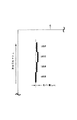
さらに、図1において中間転写ベルト6を張架している各ローラ8,9,10,11の直径と各ローラ8,9,10,11ヘの中間転写ベルト6の巻付角は以下に示す通りであった。なお、巻付角とは図5に示す部分である。また、中間転写ベルト6はテンションローラ10により総圧49Nで張架されていた。
【0084】
【0085】
【実施例2】
<エンドレスベルトの作製>
3種類の材料を下記のように配合する。
【0086】
ポリカーボネート樹脂 100 重量部
カーボンブラック 12 重量部
酸化防止剤 0.5 重量部
上記のように配合された3種類の材料を2軸の押し出し混練機で混練せしめ、カーボンブラック等添加剤を充分にバインダー中に均一分散させ、成型用原料を得た。更にこれを1〜2mmの粒径の混練物とした後、一軸押し出し機のホッパーヘ投入し、温度を270〜290℃の範囲に調節して押し出すことにより、溶融体とした。
【0087】
次に、この溶融体を直径200mm、ダイギャップ900μmの円筒状単層用押し出しダイスに導いた後、そこで空気導入路より空気を吹き込んで拡大膨張させ、最終的な形状寸法として直径250mm、厚み150μmとした。更にベルト巾350mmで切断し、シームレスベルトを得た。
【0088】
一方、補強部材として、ポリエチレンテレフタレート樹脂からなる補強テープを用いて、シームレスベルトの外局面の両端部に貼着して、外周面に補強部材を有するシームレスベルトを得た。
<エンドレスベルトヘの蛇行防止部材の接合>
実施例1と同様の蛇行防止部材を、上記のようにして得られた補強部材を有するエンドレスベルトの内周面にアクリル系粘着剤を有する両面テープで貼着して蛇行防止部材を有するエンドレスベルトを得た。
【0089】
得られた蛇行防止部材を有するエンドレスベルトを図2の構成のカラーレーザープリンタの転写搬送ベルト61として組込み、転写搬送ベルト61の4万回転に相当するフルカラー10万枚の耐久試験を行った。その結果、蛇行防止部材の剥離及びベルト端部に割れや欠けなどの不具合は発生せず、十分な耐久性を有していた。また色ズレ量も平均で約50μmと良好であった。
【0090】
更に、同様にして作製した蛇行防止部材を有する未耐久エンドレスベルトにおける蛇行防止部材のエンドレスベルトヘの接合強度と、耐久試験後における蛇行防止部材のエンドレスベルトヘの接合強度を比較したところ、未耐久ベルトの約80%の接合強度を保持していた。ここで、ベルトの接合強度の測定は、90°剥離強度を測定して接合強度とした。
【0091】
図2において転写搬送ベルト61を張架している各ローラ9,91,10の直径と各ローラヘの転写搬送ベルト61の巻付角は以下に示す通りであった。また、転写搬送ベルト61はテンションローラ10により総圧68.6Nで張架されていた。
【0092】
【0093】
【実施例3】
<エンドレスベルトの作製>
実施例1と同様の方法で内周面に補強部材を有するシームレスベルトを得た。<エンドレスベルトヘの蛇行防止部材の接合>
上記のようにして得られたシームレスベルトの補強部材内周面上に厚さ2mm、幅3mmの断面形状が長方形で、断面の4辺にスキン層を有するポリウレタン発泡体を、アクリル系粘着剤を有する両面テープで貼着して、蛇行防止部材を有するエンドレスベルトを得た。ここで、スキン層の厚みは2μmでスキン層の空隙率は8%であった。また、発泡体の平均発泡径は12μmで発泡体の空隙率は25%であった。
【0094】
得られた蛇行防止部材を有するエンドレスベルトを図1の構成のカラーレーザープリンタの中間転写ベルト6として組込み、中間転写ベルト6の4万回転に相当するフルカラー1万枚の耐久試験を行った。その結果、蛇行防止部材の剥離及びベルト端部に割れや欠けなどの不具合は発生せず、十分な耐久性を有していた。また色ズレ量も平均で約40μmと良好であった。
【0095】
更に、同様にして作製した蛇行防止部材を有する未耐久エンドレスベルトにおける蛇行防止部材のエンドレスベルトヘの接合強度と、耐久試験後における蛇行防止部材のエンドレスベルトヘの接合強度を比較したところ、未耐久ベルトの約50%の接合強度を保持していた。ここで、ベルトの接合強度の測定は、90°剥離強度を測定して接合強度とした。
【0096】
【実施例4】
<エンドレスベルトの作製>
実施例1と同様の方法で内周面に補強部材を有するシームレスベルトを得た。
<エンドレスベルトヘの蛇行防止部材の接合>
上記のようにして得られたシームレスベルトの補強部材内周面上に厚さ2mm、幅3mmの断面形状が長方形で、断面の4辺にスキン層を有するポリウレタン発泡体を、アクリル系粘着剤を有する両面テープで貼着して、蛇行防止部材を有するエンドレスベルトを得た。ここで、スキン層の厚みは8μmでスキン層の空隙率は25%であった。また、発泡体の平均発泡径は270μmで発泡体の空隙率は70%であった。
【0097】
得られた蛇行防止部材を有するエンドレスベルトを図1の構成のカラーレーザープリンタの中間転写ベルト6として組込み、中間転写ベルト6の4万回転に相当するフルカラー1万枚の耐久試験を行った。その結果、蛇行防止部材の剥離及びベルト端部に割れや欠けなどの不具合は発生せず、十分な耐久性を有していた。色ズレ量は平均で約90μmと良好であった。
【0098】
更に、同様にして作製した蛇行防止部材を有する未耐久エンドレスベルトにおける蛇行防止部材のエンドレスベルトヘの接合強度と、耐久試験後における蛇行防止部材のエンドレスベルトヘの接合強度を比較したところ、未耐久ベルトの約90%の接合強度を保持していた。ここで、ベルトの接合強度の測定は、90°剥離強度を測定して接合強度とした。
【0099】
【実施例5】
<エンドレスベルトの作製>
実施例1と同様の方法で内周面に補強部材を有するシームレスベルトを得た。
<エンドレスベルトヘの蛇行防止部材の接合>
上記のようにして得られたシームレスベルトの補強部材内周面上に厚さ2mm、幅3mmの断面形状が長方形で、スキン層を有さないポリウレタン発泡体を、アクリル系粘着剤を有する両面テープで貼着して、蛇行防止部材を有するエンドレスベルトを得た。ここで、発泡体の平均発泡径は50μmで発泡体の空隙率は50%であった。
【0100】
得られた蛇行防止部材を有するエンドレスベルトを図1の構成のカラーレーザープリンタの中間転写ベルト6として組込み、中間転写ベルト6の4万回転に相当するフルカラー1万枚の耐久試験を行った。その結果、蛇行防止部材の剥離及びベルト端部に割れや欠けなどの不具合は発生せず、十分な耐久性を有していた。色ズレ量は平均で約80μmと良好であった。
【0101】
更に、同様にして作製した蛇行防止部材を有する未耐久エンドレスベルトにおける蛇行防止部材のエンドレスベルトヘの接合強度と、耐久試験後における蛇行防止部材のエンドレスベルトヘの接合強度を比較したところ、未耐久ベルトの約75%の接合強度を保持していた。ここで、ベルトの接合強度の測定は、90°剥離強度を測定して接合強度とした。
【0102】
【実施例6】
<エンドレスベルトの作製>
実施例1と同様の方法で内周面に補強部材を有するシームレスベルトを得た。
<エンドレスベルトヘの蛇行防止部材の接合>
上記のようにして得られたシームレスベルトの補強部材内周面上に厚さ2mm、幅3mmの断面形状が長方形で、断面の4辺にスキン層を有するポリウレタン発泡体を、アクリル系粘着剤を有する両面テープで貼着して、蛇行防止部材を有するエンドレスベルトを得た。ここで、スキン層の厚みは1μmでスキン層の空隙率は5%であった。また、発泡体の平均発泡径は10μmで発泡体の空隙率は15%であった。
【0103】
得られた蛇行防止部材を有するエンドレスベルトを図1の構成のカラーレーザープリンタの中間転写ベルト6として組込み、中間転写ベルト6の4万回転に相当するフルカラー1万枚の耐久試験を行った。その結果、蛇行防止部材の剥離及びベルト端部に割れや欠けなどの不具合は発生せず、十分な耐久性を有していた。色ズレ量は平均で約40μmと良好であった。
【0104】
更に、同様にして作製した蛇行防止部材を有する未耐久エンドレスベルトにおける蛇行防止部材のエンドレスベルトヘの接合強度と、耐久試験後における蛇行防止部材のエンドレスベルトヘの接合強度を比較したところ、未耐久ベルトの約30%の接合強度を保持していた。ここで、ベルトの接合強度の測定は、90°剥離強度を測定して接合強度とした。
【0105】
【実施例7】
<エンドレスベルトの作製>
実施例1と同様の方法で内周面に補強部材を有するシームレスベルトを得た。
<エンドレスベルトヘの蛇行防止部材の接合>
上記のようにして得られたシームレスベルトの補強部材内周面上に厚さ2mm、幅3mmの断面形状が長方形で、スキン層を有さないポリウレタン発泡体を、アクリル系粘着剤を有する両面テープで貼着して、蛇行防止部材を有するエンドレスベルトを得た。ここで、発泡体の平均発泡径は330μmで発泡体の空隙率は82%であった。
【0106】
得られた蛇行防止部材を有するエンドレスベルトを図1の構成のカラーレーザープリンタの中間転写ベルト6として組込み、中間転写ベルト6の4万回転に相当するフルカラー1万枚の耐久試験を行った。その結果、蛇行防止部材の剥離及びベルト端部に割れや欠けなどの不具合は発生せず、十分な耐久性を有していた。色ズレ量は平均で約120μmと大き目であったが、十分実用に耐え得るレベルであった。
【0107】
更に、同様にして作製した蛇行防止部材を有する未耐久エンドレスベルトにおける蛇行防止部材のエンドレスベルトヘの接合強度と、耐久試験後における蛇行防止部材のエンドレスベルトヘの接合強度を比較したところ、未耐久ベルトの約90%の接合強度を保持していた。ここで、ベルトの接合強度の測定は、90°剥離強度を測定して接合強度とした。
【0108】
次に、比較例について説明する。
【0109】
【比較例1】
<エンドレスベルトの作製>
既述した実施例1と同様の方法で内周面に補強部材を有するシームレスベルトを得た。
【0110】
そして、この補強部材を有するシームレスベルトを蛇行防止部材を設けずに図1の構成のカラーレーザープリンタの中間転写ベルト6として組込み、フルカラー耐久試験を行った。その結果、蛇行によりローラの一方向にベルトが寄ってしまったことによる応力のため、約50枚画像を出力したところでベルト端部に割れが発生したので耐久試験を中止した。
【0111】
【比較例2】
<エンドレスベルトの作製>
既述した実施例2と同様の方法で外周面に補強部材を有するシームレスベルトを得た。
<エンドレスベルトヘの蛇行防止部材の接合>
上記のようにして得られた補強部材を有するシームレスベルトの内周面上に厚さ2mm、幅3mmの断面形状が長方形のポリウレタンエラストマーよりなる蛇行防止部材を、アクリル系粘着剤を有する両面テープで貼着して、蛇行防止部材を有するエンドレスベルトを得た。
【0112】
得られた蛇行防止部材を有するエンドレスベルトを図2の構成のカラーレーザープリンタの転写搬送ベルト61として組込み、フルカラー耐久試験を行った。その結果、約5万枚耐久(転写搬送ベルト約2万回転)した時点で蛇行防止部材が剥離したことにより、画像形成装置が脱調し、画像出力不可能となったので耐久試験を中止した。また、その時点で耐久ベルトを目視により確認したところ、ベルト端部に微少な亀裂が多数見られた。
【0113】
【発明の効果】
以上説明したように本発明のように、無端状のベルト本体の内周面の少なくとも一側部に設けられる蛇行防止部材を発泡体によって形成することにより、蛇行防止部材の剥離及びベルトの破損を防止することができ、これにより耐久寿命の長いベルトを得ることができる。また、蛇行防止部材を発泡体によって形成することにより、ベルトを張架するローラの直径が小さく、また巻付角が大きい場合でも、蛇行防止部材の剥離及びベルトの破損を防止することができ、これにより画像形成装置の小型化を図ることができる。
【図面の簡単な説明】
【図1】本発明の実施の形態に係るベルトの一例である中間転写ベルトを用いる画像形成装置の概略構成を示す図。
【図2】本発明の実施の形態に係るベルトの一例である転写搬送ベルトを用いる画像形成装置の概略構成を示す図。
【図3】上記ベルト(中間転写ベルト及び転写搬送ベルト)の構造を示す図。
【図4】上記ベルト(中間転写ベルト及び転写搬送ベルト)における色ズレを求める方法を説明する図。
【図5】上記ベルト(中間転写ベルト及び転写搬送ベルト)のローラヘの巻付角を示す図。
【符号の説明】
1,1Y,1M,1C,1K
感光ドラム
2 コロナチャージャ
2Y,2M,2C,2K
一次帯電ローラ
41〜44,4Y,4M,4C,4K
現像器
6 中間転写ベルト
6a ベルト本体
6b 蛇行防止部材
6c スキン層
8 一次転写ローラ
8Y,8M,8C,8K
転写シート
9,91 駆動ローラ
10 テンションローラ
11 二次転写対向ローラ
12 二次転写ローラ
13 転写材
61 転写搬送ベルト
61a ベルト本体
61b 蛇行防止部
61c スキン層
R ローラ
R1 溝[0001]
BACKGROUND OF THE INVENTION
The present invention relates to a belt and an image forming apparatus including the belt, and more particularly to a meandering prevention member provided on an inner peripheral surface of an endless belt.
[0002]
[Prior art]
In an image forming apparatus such as a conventional electrophotographic apparatus, an endless belt is used as a belt-like photoreceptor, an intermediate transfer belt, a transfer belt, a paper conveyance belt, a fixing belt, or the like.
[0003]
Here, such an endless belt is generally supported by two or more rollers and is driven to rotate while being given an arbitrary tension. The straightness or roundness of the supporting rollers depends on the axis of each roller. The parallelism of the belt and the roundness of the endless belt itself have slight errors and variations, and therefore may meander to the left and right during rotational driving. When such an endless belt is used as a transfer belt for a full-color electrophotographic apparatus or the like where accuracy is required, the image forming position of each color shifts when the color is superimposed on the transfer belt due to the meandering of the transfer belt. Deviation occurs.
[0004]
Therefore, in order to prevent such meandering, a meandering prevention member is provided on the entire inner circumference of the transfer belt, and a groove is provided on a roller on which the transfer belt is stretched, and the meandering prevention member is locked in this groove. By rotating the roller while rotating, the transfer belt can be smoothly run without meandering, whereby a good image without color misregistration can be formed.
[0005]
[Problems to be solved by the invention]
However, in the transfer belt having this configuration, the meandering prevention member may be peeled off from the transfer belt due to the stress caused by the deformation of the meandering prevention member by a roller or the like, or the transfer belt may be cracked in some cases.
[0006]
For this reason, for example, an acrylic foam is used for a belt reinforcing base as in JP-A-08-099706, and a polyurethane sheet having a prescribed hardness is adhered thereon, thereby providing a meandering prevention effect and a stress relaxation effect on the belt. There is something to play.
[0007]
However, in such a configuration, since the non-foam occupies most of the thickness of the meandering prevention member, the meandering prevention member is greatly deformed at the belt bending portion and receives a great deal of stress. The meandering-preventing member may peel off.
[0008]
This phenomenon is particularly remarkable when the diameter of the roller that stretches the transfer belt is small and the winding angle of the transfer belt with respect to the roller is large. In other words, in order to satisfy the life of the transfer belt, it is necessary to increase the diameter of the roller on which the transfer belt is stretched and to reduce the winding angle of the transfer belt on the roller, that is, to make the roller multi-axial. This is a great barrier to downsizing the image forming apparatus.
[0009]
Therefore, the present invention has been made in view of such a situation, and an object thereof is to provide a belt having a long durability life and an image forming apparatus including the belt.
[0010]
[Means for Solving the Problems]
The present invention has an endless belt body and a meandering prevention member provided on an inner peripheral surface of the belt body, the belt body is stretched by a tension member, and the belt body and the meandering prevention member Is movable, and the meander-preventing member is in contact with the stretching member and restricts movement of the belt body and the meander-preventing member in a direction perpendicular to the moving direction of the belt. The meander-preventing member is a foam. And a layer having voids at a rate lower than that of the foam is formed on the surface of the meandering prevention member that is joined to the belt body and the surface that is in contact with the tension member. The meandering prevention member is a layer having a square or rectangular cross-sectional shape in a direction perpendicular to the moving direction of the belt, and having voids at a ratio lower than that of the foam on all four sides of the square or rectangle. The porosity of the foam is 20% or more and 80% or less, and the porosity of the layer having voids at a rate lower than the foam is less than 20%. It is characterized by this.
[0012]
In the present invention, the meandering prevention member is Tension member On the side edge Therefore, the movement of the belt body and the meandering prevention member in the direction orthogonal to the moving direction is restricted. It is characterized by that.
[0013]
In the present invention, the foam has an average foam diameter of 10 μm or more and 300 μm or less.
[0017]
The present invention also provides Layer having voids at a lower porosity than the foam The thickness is 100 μm or less.
[0018]
According to the present invention, the belt body is a seamless belt having no joints.
[0019]
The present invention also provides Carrying a toner image An image carrier; Above An intermediate transfer belt to which a toner image formed on an image carrier is transferred, and the toner image on the intermediate transfer belt is transferred to a transfer material. It is a belt as described in the above.
[0020]
The present invention also provides Carrying a toner image With image carrier , Roll Assisting the photocopying material Hold Transfer transfer belt The toner image on the image carrier is transferred to a transfer material on the transfer conveyance belt. In the image forming apparatus, the transfer conveyance belt is any one of the above-described belts.
[0021]
Further, by configuring as in the present invention, the toner image formed on the image carrier on the outer peripheral surface is provided on at least one side of the inner peripheral surface of the endless belt body, and is formed on the roller. By forming the meandering prevention member to be locked in the locking groove from a foam, peeling of the meandering prevention member from the belt main body and damage to the belt main body are prevented.
[0022]
DETAILED DESCRIPTION OF THE INVENTION
Hereinafter, embodiments of the present invention will be described in detail with reference to the drawings.
[0023]
FIG. 1 is a diagram showing a schematic configuration of a laser color printer (image forming apparatus) using an intermediate transfer belt which is an example of a belt according to an embodiment of the present invention.
[0024]
In the figure, reference numeral 1 denotes a drum-shaped electrophotographic photosensitive member (hereinafter referred to as a photosensitive drum) as a first image bearing member, which is driven to rotate at a predetermined peripheral speed (process speed) in the direction of an arrow. It has become.
[0025]
Reference numeral 2 denotes a corona charger that uniformly charges the surface of the photosensitive drum 1 to a predetermined polarity and potential, and
[0026]
[0027]
The
[0028]
[0029]
Reference numeral 17 denotes a fixing device that heats and fixes the transferred toner image on the
[0030]
Next, an image forming operation of the image forming apparatus having such a configuration will be described.
[0031]
When forming an image, first, the surface of the photosensitive drum 1 is uniformly charged to a predetermined polarity and potential by the corona charger 2 during the rotation of the photosensitive drum 1. Next, an electrostatic latent image corresponding to a first color component (for example, a magenta component image) of a target color image is formed on the surface of the photosensitive drum 1 by exposure 3 from an image exposure unit (not shown).
[0032]
Next, the electrostatic latent image is developed by a first developing device 41 (magenta developing device), and then the first color magenta toner image formed and supported on the photosensitive drum 1 is moved in the direction of the arrow. A primary transfer is applied to the
[0033]
Similarly, the second color cyan toner image, the third color yellow toner image, and the fourth color black toner image are successively superimposed and transferred onto the
[0034]
Next, the full color image superimposed and transferred on the
[0035]
Then, the
[0036]
On the other hand, FIG. 2 is a diagram showing a schematic configuration of an image forming apparatus using a transfer conveyance belt which is an example of a belt according to an embodiment of the present invention. In the figure, the same reference numerals as those in FIG. 1 denote the same or corresponding parts. The image forming apparatus is a tandem laser color printer in which image forming stations of a plurality of colors (for example, yellow, magenta, cyan, and black) are arranged.
[0037]
In the figure, 20Y, 20M, 20C, and 20K are first to fourth image forming stations, and these
[0038]
[0039]
[0040]
Next, an image forming operation of the image forming apparatus having such a configuration will be described.
[0041]
When forming an image, first, as a charging process, the surface of the
[0042]
Next, the electrostatic latent image is developed by the first developing
[0043]
Next, the residual toner that has not been transferred from the
[0044]
Further, in the second to fourth
[0045]
Thereafter, the
[0046]
By the way, the
[0047]
However, since the
[0048]
Therefore, in the present embodiment, a foam is used as the meandering preventing
[0049]
Here, the average foam diameter of the foam is preferably 10 μm or more and 300 μm or less. When the average foam diameter is less than 10 μm, the meandering
[0050]
The porosity of the foam is preferably 20% or more and 80% or less. When the porosity is less than 20%, the
[0051]
Further, at least one of the surface where the
[0052]
And by having
[0053]
Here, such an effect is remarkably exhibited when the porosity of the skin layers 6c and 61c is less than 20%. Moreover, it is preferable that the thickness of the skin layers 6c and 61c is 100 micrometers or less. If the skin layer exceeds 100 μm, the flexibility of the meandering preventing
[0054]
Moreover, it is preferable that the belt
[0055]
By the way, the material of the foam constituting the meandering preventing
[0056]
Further, the cross-sectional shape of the meandering preventing
[0057]
In the present embodiment, the case where the
[0058]
On the other hand, the flexible belt
[0059]
Specifically, polyethylene (high density, medium density, low density, linear low density, etc.), polypropylene, polystyrene, ethylene-vinyl alcohol copolymer (EVOH), polycarbonate, polyamide, polyacetal, polyarylate, polyphenylene ether , Modified polyphenylene ether, polyimide, liquid crystalline polymer, polysulfone, polyethersulfone, polyphenylene sulfite, polybisamide triazole, polyetherimide, polyamideimide, polyetheretherketone, aliphatic polyketone, polymethylpentene, polybutylene terephthalate, Polyethylene terephthalate, polyethylene naphthalate, polyvinyl fluoride, polyvinylidene fluoride (PVdF), chlorotrifluoroethylene, ethylene tetrafluoride Emissions copolymer (ETFE), hexafluoropropylene, perfluoroalkyl vinyl ether copolymer, it is possible to use a methacrylic resin, one kind or two kinds or more selected from such various other copolymers.
[0060]
In particular, but not limited to these, polycarbonate, polyvinylidene fluoride (PVdF), polysulfone, polyimide, polyphenylene sulfide, polyarylate, ethylene tetrafluoride ethylene copolymer, considering the mechanical properties and moldability of the belt Combined (ETFE) is preferred.
[0061]
For the purpose of imparting conductivity to these resins, various conductive agents such as carbon black such as acetylene black, furnace black and channel black, titanium oxide, potassium titanate, tin oxide, lithium salt, quaternary ammonium salt and the like. May be added.
[0062]
Furthermore, fillers such as talc, mica and calcium carbonate, flame retardants such as magnesium hydroxide and antimony trioxide, and additives such as antioxidants (phenolic and sulfur based) may be added. Of course, the additive is not limited to the above-mentioned substances, and any other additive can be used.
[0063]
Here, as a method of adding an additive to the resin, after premixing, a method of kneading and dispersing using a known kneader such as a single screw extruder, a twin screw extruder, a Banbury mixer, a roller, or a kneader Is mentioned. Normally, each component is kneaded in an extruder or the like to form a beret-like compound and then molded, but in special cases, each component is directly supplied to the molding machine and the composition is kneaded with the molding machine. It can also be molded.
[0064]
On the other hand, as a manufacturing method of the belt
[0065]
Here, the thickness of the
[0066]
Furthermore, the
[0067]
On the other hand, the joining method of the meandering preventing
[0068]
Further, for the purpose of reinforcing or improving the joining strength between the belt
[0069]
Furthermore, various surface treatments such as corona treatment can be applied to the joint surfaces of the
[0070]
Next, a method for measuring the average foam diameter and porosity of the foam will be described.
[0071]
When performing the measurement, first, the meandering
[0072]
Next, it is enlarged using a microscope (optical microscope, scanning electron condyle microscope, etc.), and an arbitrary measurement range S (μm 2 ) Count the number of cells per cell, and measure the diameter R (μm) of each cell. Here, when the shape of the cell is indefinite, the outer periphery of the cell is measured, and a circle and a cell having the same outer periphery as the actually measured external station are assumed to be the cell diameter. Conditions for easy measurement can be selected for the enlargement magnification and the measurement range in consideration of the cell size and the like, but the measurement range is set so that the number of cells to be counted is 50 or more.
[0073]
[Formula 1]
[0074]
[Formula 2]
[0075]
Next, examples of the present embodiment will be described.
[0076]
[Example 1]
<Production of endless belt>
Three kinds of materials are blended as follows.
[0077]
100 parts by weight of polycarbonate resin
15 parts by weight of carbon black
Antioxidant 0.5 parts by weight
The three types of materials blended as described above were kneaded with a biaxial extrusion kneader, and additives such as carbon black were sufficiently uniformly dispersed in a binder to obtain a molding material. Further, this was made into a kneaded product having a particle diameter of 1 to 2 mm, and then charged into a hopper of a single screw extruder, and adjusted to a temperature of 270 to 290 ° C. and extruded to obtain a melt.
[0078]
Next, this melt was introduced into a cylindrical single-layer extrusion die having a diameter of 100 mm and a die gap of 900 μm, and then expanded by blowing air from an air introduction path, resulting in a final shape of 140 mm in diameter and 150 μm in thickness. did. Further, the belt was cut at a width of 250 mm to obtain a seamless belt.
[0079]
On the other hand, a reinforcing tape made of polyethylene terephthalate resin was used as the reinforcing member and adhered to both end portions of the inner peripheral surface of the seamless belt to obtain a seamless belt having the reinforcing member on the inner peripheral surface.
<Join the meandering prevention member to the endless belt>
Next, a polyurethane foam having a rectangular cross-section of 2 mm in thickness and 3 mm in width on the inner peripheral surface of the reinforcing member of the seamless belt thus obtained and having a skin layer on four sides of the cross-section is an acrylic pressure-sensitive adhesive. An endless belt having a meandering-preventing member was obtained by sticking with a double-sided tape having Here, the thickness of the skin layer was about 3 μm, and the porosity of the skin layer was 10%. The average foam diameter of the foam was 50 μm, and the porosity of the foam was 50%.
[0080]
The endless belt having the meander-preventing member thus obtained is incorporated as an
[0081]
Note that the average value of the color misregistration amount is obtained by outputting a line image (image having a line width of 200 μm or less) as shown in FIG. Was determined by
[0082]
Furthermore, when the joining strength of the meandering prevention member to the endless belt in the non-durable endless belt having the meandering prevention member produced in the same manner was compared with the joining strength of the meandering prevention member to the endless belt after the durability test, The joint strength of about 90% of the belt was maintained. Here, the bonding strength of the belt was measured by measuring the 90 ° peel strength as the bonding strength.
[0083]
Further, in FIG. 1, the diameters of the
[0084]
[0085]
[Example 2]
<Production of endless belt>
Three kinds of materials are blended as follows.
[0086]
100 parts by weight of polycarbonate resin
12 parts by weight of carbon black
Antioxidant 0.5 parts by weight
The three types of materials blended as described above were kneaded with a biaxial extrusion kneader, and additives such as carbon black were sufficiently uniformly dispersed in a binder to obtain a molding material. Further, this was made into a kneaded product having a particle diameter of 1 to 2 mm, and then charged into a hopper of a single screw extruder, and adjusted to a temperature of 270 to 290 ° C. and extruded to obtain a melt.
[0087]
Next, this melt was introduced into an extrusion die for a cylindrical single layer having a diameter of 200 mm and a die gap of 900 μm, and then expanded and expanded by blowing air from an air introduction path, with a final shape dimension of 250 mm in diameter and 150 μm in thickness. It was. Furthermore, it cut | disconnected with the belt width 350mm, and obtained the seamless belt.
[0088]
On the other hand, a reinforcing tape made of polyethylene terephthalate resin was used as the reinforcing member, and was stuck to both ends of the outer surface of the seamless belt to obtain a seamless belt having a reinforcing member on the outer peripheral surface.
<Join the meandering prevention member to the endless belt>
An endless belt having a meandering prevention member obtained by sticking the same meandering prevention member as in Example 1 to the inner peripheral surface of an endless belt having a reinforcing member obtained as described above with a double-sided tape having an acrylic adhesive. Got.
[0089]
The obtained endless belt having the meandering preventing member was incorporated as a
[0090]
Furthermore, when the joining strength of the meandering prevention member to the endless belt in the non-durable endless belt having the meandering prevention member produced in the same manner was compared with the joining strength of the meandering prevention member to the endless belt after the durability test, The joint strength of about 80% of the belt was maintained. Here, the bonding strength of the belt was measured by measuring the 90 ° peel strength as the bonding strength.
[0091]
In FIG. 2, the diameters of the
[0092]
[0093]
[Example 3]
<Production of endless belt>
A seamless belt having a reinforcing member on the inner peripheral surface was obtained in the same manner as in Example 1. <Join the meandering prevention member to the endless belt>
A polyurethane foam having a rectangular cross section with a thickness of 2 mm and a width of 3 mm on the inner peripheral surface of the reinforcing member of the seamless belt obtained as described above, and having a skin layer on the four sides of the cross section, an acrylic adhesive The endless belt which has a meandering prevention member was obtained by sticking with a double-sided adhesive tape. Here, the thickness of the skin layer was 2 μm, and the porosity of the skin layer was 8%. The average foam diameter of the foam was 12 μm, and the porosity of the foam was 25%.
[0094]
The obtained endless belt having the meandering preventing member was incorporated as an
[0095]
Furthermore, when the joining strength of the meandering prevention member to the endless belt in the non-durable endless belt having the meandering prevention member produced in the same manner was compared with the joining strength of the meandering prevention member to the endless belt after the durability test, The joint strength of about 50% of the belt was maintained. Here, the bonding strength of the belt was measured by measuring the 90 ° peel strength as the bonding strength.
[0096]
[Example 4]
<Production of endless belt>
A seamless belt having a reinforcing member on the inner peripheral surface was obtained in the same manner as in Example 1.
<Join the meandering prevention member to the endless belt>
A polyurethane foam having a rectangular cross section with a thickness of 2 mm and a width of 3 mm on the inner peripheral surface of the reinforcing member of the seamless belt obtained as described above, and having a skin layer on the four sides of the cross section, an acrylic adhesive The endless belt which has a meandering prevention member was obtained by sticking with a double-sided adhesive tape. Here, the thickness of the skin layer was 8 μm, and the porosity of the skin layer was 25%. The average foam diameter of the foam was 270 μm, and the porosity of the foam was 70%.
[0097]
The obtained endless belt having the meandering preventing member was incorporated as an
[0098]
Furthermore, when the joining strength of the meandering prevention member to the endless belt in the non-durable endless belt having the meandering prevention member produced in the same manner was compared with the joining strength of the meandering prevention member to the endless belt after the durability test, The joint strength of about 90% of the belt was maintained. Here, the bonding strength of the belt was measured by measuring the 90 ° peel strength as the bonding strength.
[0099]
[Example 5]
<Production of endless belt>
A seamless belt having a reinforcing member on the inner peripheral surface was obtained in the same manner as in Example 1.
<Join the meandering prevention member to the endless belt>
A double-sided tape having a polyurethane foam having an acrylic adhesive and a polyurethane foam having a rectangular cross section with a thickness of 2 mm and a width of 3 mm on the inner peripheral surface of the reinforcing member of the seamless belt obtained as described above. The endless belt having a meandering prevention member was obtained. Here, the average foam diameter of the foam was 50 μm, and the porosity of the foam was 50%.
[0100]
The obtained endless belt having the meandering preventing member was incorporated as an
[0101]
Furthermore, when the joining strength of the meandering prevention member to the endless belt in the non-durable endless belt having the meandering prevention member produced in the same manner was compared with the joining strength of the meandering prevention member to the endless belt after the durability test, The joint strength of about 75% of the belt was maintained. Here, the bonding strength of the belt was measured by measuring the 90 ° peel strength as the bonding strength.
[0102]
[Example 6]
<Production of endless belt>
A seamless belt having a reinforcing member on the inner peripheral surface was obtained in the same manner as in Example 1.
<Join the meandering prevention member to the endless belt>
A polyurethane foam having a rectangular cross section with a thickness of 2 mm and a width of 3 mm on the inner peripheral surface of the reinforcing member of the seamless belt obtained as described above, and having a skin layer on the four sides of the cross section, an acrylic adhesive The endless belt which has a meandering prevention member was obtained by sticking with a double-sided adhesive tape. Here, the thickness of the skin layer was 1 μm, and the porosity of the skin layer was 5%. The average foam diameter of the foam was 10 μm, and the porosity of the foam was 15%.
[0103]
The obtained endless belt having the meandering preventing member was incorporated as an
[0104]
Furthermore, when the joining strength of the meandering prevention member to the endless belt in the non-durable endless belt having the meandering prevention member produced in the same manner was compared with the joining strength of the meandering prevention member to the endless belt after the durability test, The joint strength of about 30% of the belt was maintained. Here, the bonding strength of the belt was measured by measuring the 90 ° peel strength as the bonding strength.
[0105]
[Example 7]
<Production of endless belt>
A seamless belt having a reinforcing member on the inner peripheral surface was obtained in the same manner as in Example 1.
<Join the meandering prevention member to the endless belt>
A double-sided tape having a polyurethane foam having an acrylic adhesive and a polyurethane foam having a rectangular cross section with a thickness of 2 mm and a width of 3 mm on the inner peripheral surface of the reinforcing member of the seamless belt obtained as described above. The endless belt having a meandering prevention member was obtained. Here, the average foam diameter of the foam was 330 μm, and the porosity of the foam was 82%.
[0106]
The obtained endless belt having the meandering preventing member was incorporated as an
[0107]
Furthermore, when the joining strength of the meandering prevention member to the endless belt in the non-durable endless belt having the meandering prevention member produced in the same manner was compared with the joining strength of the meandering prevention member to the endless belt after the durability test, The joint strength of about 90% of the belt was maintained. Here, the bonding strength of the belt was measured by measuring the 90 ° peel strength as the bonding strength.
[0108]
Next, a comparative example will be described.
[0109]
[Comparative Example 1]
<Production of endless belt>
A seamless belt having a reinforcing member on the inner peripheral surface was obtained in the same manner as in Example 1 described above.
[0110]
Then, a seamless belt having this reinforcing member was incorporated as an
[0111]
[Comparative Example 2]
<Production of endless belt>
A seamless belt having a reinforcing member on the outer peripheral surface was obtained in the same manner as in Example 2 described above.
<Join the meandering prevention member to the endless belt>
A meandering prevention member made of polyurethane elastomer having a cross section of 2 mm in thickness and 3 mm in width on the inner peripheral surface of a seamless belt having a reinforcing member obtained as described above is a double-sided tape having an acrylic adhesive. By sticking, an endless belt having a meandering prevention member was obtained.
[0112]
The obtained endless belt having the meandering prevention member was incorporated as a
[0113]
【The invention's effect】
As described above, as in the present invention, the meandering prevention member provided on at least one side portion of the inner peripheral surface of the endless belt body is formed of a foam, so that the meandering prevention member is peeled off and the belt is damaged. Thus, a belt having a long durability life can be obtained. Further, by forming the meandering prevention member with a foam, the diameter of the roller for stretching the belt is small, and even when the winding angle is large, peeling of the meandering prevention member and damage to the belt can be prevented. This can reduce the size of the image forming apparatus.
[Brief description of the drawings]
FIG. 1 is a diagram showing a schematic configuration of an image forming apparatus using an intermediate transfer belt which is an example of a belt according to an embodiment of the invention.
FIG. 2 is a diagram illustrating a schematic configuration of an image forming apparatus using a transfer conveyance belt which is an example of a belt according to an embodiment of the invention.
FIG. 3 is a diagram illustrating a structure of the belt (intermediate transfer belt and transfer conveyance belt).
FIG. 4 is a diagram illustrating a method for obtaining a color shift in the belt (intermediate transfer belt and transfer conveyance belt).
FIG. 5 is a view showing a winding angle of the belt (intermediate transfer belt and transfer conveyance belt) around a roller.
[Explanation of symbols]
1,1Y, 1M, 1C, 1K
Photosensitive drum
2 Corona charger
2Y, 2M, 2C, 2K
Primary charging roller
41-44, 4Y, 4M, 4C, 4K
Developer
6 Intermediate transfer belt
6a Belt body
6b Meander prevention member
6c Skin layer
8 Primary transfer roller
8Y, 8M, 8C, 8K
Transfer sheet
9,91 Drive roller
10 Tension roller
11 Secondary transfer counter roller
12 Secondary transfer roller
13 Transfer material
61 Transfer conveyor belt
61a Belt body
61b Meander prevention part
61c Skin layer
R roller
R1 groove
Claims (6)
前記蛇行防止部材は発泡体であり、前記蛇行防止部材の前記ベルト本体と接合する面及び前記張架部材と接する面に前記発泡体よりも空隙率が低い割合で空隙を有する層が形成されており、前記蛇行防止部材は前記ベルトの移動方向と垂直な方向の断面形状が正方形又は長方形であり、前記正方形又は長方形の4辺全てに前記発泡体よりも空隙率が低い割合で空隙を有する層が形成されており、前記発泡体の空隙率が20%以上80%以下であり、前記発泡体よりも空隙率が低い割合で空隙を有する層の空隙率が20%未満であることを特徴とするベルト。An endless belt body and a meandering prevention member provided on an inner peripheral surface of the belt body, the belt body is stretched by a tension member, and the belt body and the meandering prevention member are movable. Yes, in the belt where the meandering prevention member is in contact with the tension member and restricts the movement of the belt body and the meandering prevention member in the direction perpendicular to the movement direction,
The meander-preventing member is a foam, and a layer having voids at a ratio lower than that of the foam is formed on the surface of the meandering-preventing member that is joined to the belt body and the surface that is in contact with the stretching member. The meandering prevention member has a square or rectangular cross-sectional shape in a direction perpendicular to the moving direction of the belt, and a layer having voids on all four sides of the square or rectangle at a lower porosity than the foam. The porosity of the foam is 20% or more and 80% or less, and the porosity of the layer having voids at a rate lower than that of the foam is less than 20%. To belt.
前記中間転写ベルトは、請求項1ないし4のいずれか1項に記載のベルトであることを特徴とする画像形成装置。An image forming apparatus comprising: an image carrier that carries a toner image; and an intermediate transfer belt to which the toner image formed on the image carrier is transferred, wherein the toner image on the intermediate transfer belt is transferred to a transfer material In
The intermediate transfer belt, an image forming apparatus which is a belt according to any one of 請 Motomeko 1-4.
前記転写搬送ベルトは、請求項1ないし4のいずれか1項に記載のベルトであることを特徴とする画像形成装置。In an image carrier that carries a toner image, a transfer conveyance belt that carries a transfer material, and an image forming apparatus that transfers a toner image on the image carrier to a transfer material on the transfer conveyance belt,
The transfer conveyor belt, an image forming apparatus which is a belt according to any one of 請 Motomeko 1-4.
Priority Applications (4)
| Application Number | Priority Date | Filing Date | Title |
|---|---|---|---|
| JP30167599A JP4365954B2 (en) | 1999-10-22 | 1999-10-22 | Belt and image forming apparatus having the same |
| CN00802370.0A CN1210196C (en) | 1999-10-22 | 2000-10-23 | Belt and image forming device with the belt |
| PCT/JP2000/007364 WO2001028897A1 (en) | 1999-10-22 | 2000-10-23 | Belt and image forming device with the belt |
| US09/722,548 US6674989B1 (en) | 1999-10-22 | 2000-11-28 | Endless belt with serpentine motion preventing member and image forming apparatus including same |
Applications Claiming Priority (1)
| Application Number | Priority Date | Filing Date | Title |
|---|---|---|---|
| JP30167599A JP4365954B2 (en) | 1999-10-22 | 1999-10-22 | Belt and image forming apparatus having the same |
Related Child Applications (1)
| Application Number | Title | Priority Date | Filing Date |
|---|---|---|---|
| JP2009107981A Division JP4845994B2 (en) | 2009-04-27 | 2009-04-27 | Belt and image forming apparatus having the same |
Publications (3)
| Publication Number | Publication Date |
|---|---|
| JP2001122417A JP2001122417A (en) | 2001-05-08 |
| JP2001122417A5 JP2001122417A5 (en) | 2006-12-07 |
| JP4365954B2 true JP4365954B2 (en) | 2009-11-18 |
Family
ID=17899788
Family Applications (1)
| Application Number | Title | Priority Date | Filing Date |
|---|---|---|---|
| JP30167599A Expired - Fee Related JP4365954B2 (en) | 1999-10-22 | 1999-10-22 | Belt and image forming apparatus having the same |
Country Status (4)
| Country | Link |
|---|---|
| US (1) | US6674989B1 (en) |
| JP (1) | JP4365954B2 (en) |
| CN (1) | CN1210196C (en) |
| WO (1) | WO2001028897A1 (en) |
Families Citing this family (15)
| Publication number | Priority date | Publication date | Assignee | Title |
|---|---|---|---|---|
| JP5057623B2 (en) * | 2001-09-27 | 2012-10-24 | 株式会社ブリヂストン | Conductive endless belt and image forming apparatus using the same |
| US6778802B2 (en) | 2002-03-20 | 2004-08-17 | Ricoh Company, Ltd. | Image transferring and sheet separating device and image forming apparatus including the same |
| JP2004094177A (en) | 2002-04-26 | 2004-03-25 | Canon Inc | Electrophotographic endless belt, process cartridge, and electrophotographic system |
| US6928256B2 (en) * | 2002-09-30 | 2005-08-09 | Canon Kabushiki Kaisha | Electrophotographic endless belt, process cartridge, and electrophotographic apparatus |
| JP4439355B2 (en) * | 2004-08-06 | 2010-03-24 | シャープ株式会社 | Image forming apparatus |
| JP5477797B2 (en) * | 2005-11-02 | 2014-04-23 | 日東電工株式会社 | Endless belt with meander prevention guide |
| JP2007233167A (en) * | 2006-03-02 | 2007-09-13 | Fuji Xerox Co Ltd | Endless belt and image forming apparatus |
| US7681717B2 (en) * | 2006-03-14 | 2010-03-23 | Thermodrive Llc | Conveyor belt with attached strips of teeth |
| JP4858770B2 (en) * | 2006-10-04 | 2012-01-18 | 富士ゼロックス株式会社 | Conveying apparatus and image forming apparatus |
| JP5129030B2 (en) * | 2007-06-11 | 2013-01-23 | 京セラドキュメントソリューションズ株式会社 | Belt body, belt conveying device, and image forming apparatus |
| US20090226224A1 (en) * | 2008-03-10 | 2009-09-10 | Kabushiki Kaisha Toshiba | Image forming apparatus and transfer belt turning method for image forming apparatus |
| JP5277744B2 (en) * | 2008-06-12 | 2013-08-28 | 株式会社リコー | Image forming apparatus, intermediate transfer belt drive control method, computer program, and recording medium |
| JP2016057502A (en) * | 2014-09-10 | 2016-04-21 | 富士ゼロックス株式会社 | Endless belt, fixing device, and image forming apparatus |
| JP2017107027A (en) | 2015-12-09 | 2017-06-15 | 富士ゼロックス株式会社 | Belt-like body, image conveyance device, and image forming apparatus |
| JP6866733B2 (en) * | 2017-04-04 | 2021-04-28 | 横浜ゴム株式会社 | Conveyor belt |
Family Cites Families (15)
| Publication number | Priority date | Publication date | Assignee | Title |
|---|---|---|---|---|
| JPS59140206U (en) * | 1983-03-11 | 1984-09-19 | 昭和電工建材株式会社 | belt conveyor |
| JPS6332816U (en) * | 1986-08-18 | 1988-03-03 | ||
| DE69414047T2 (en) * | 1993-07-30 | 1999-04-22 | Canon K.K., Tokio/Tokyo | Charging part, charging device and process cassette removable from an image forming device |
| US5369477A (en) * | 1993-12-07 | 1994-11-29 | Hewlett-Packard Company | Liquid electrophotography fluid containment and belt tracking device |
| JP3104547B2 (en) * | 1994-09-30 | 2000-10-30 | 三菱化学株式会社 | Meandering prevention guide |
| EP0740221B1 (en) | 1995-04-26 | 2001-10-10 | Canon Kabushiki Kaisha | Image forming apparatus and intermediate transfer member |
| JPH09114266A (en) * | 1995-10-18 | 1997-05-02 | Minolta Co Ltd | Image forming device |
| US5995794A (en) | 1997-02-28 | 1999-11-30 | Canon Kabushiki Kaisha | Image forming apparatus and intermediate transfer belt |
| US6038415A (en) * | 1997-07-18 | 2000-03-14 | Minolta Co., Ltd. | Image forming apparatus and image-carrier cartridge device which is employed in the same |
| TW405064B (en) * | 1997-11-29 | 2000-09-11 | Fuji Xerox Co Ltd | Image formation apparatus using endless belt |
| JPH11202643A (en) * | 1998-01-16 | 1999-07-30 | Toshiba Corp | Image forming device |
| JPH11249450A (en) * | 1998-03-03 | 1999-09-17 | Bridgestone Corp | Intermediate transfer belt and intermediate transfer device |
| EP1003261B1 (en) * | 1998-11-18 | 2008-11-05 | CCS Technology, Inc. | Sealing insert for cable fittings |
| JP2000155478A (en) * | 1998-11-24 | 2000-06-06 | Minolta Co Ltd | Belt driving device |
| JP2000337464A (en) * | 1999-05-27 | 2000-12-05 | Fuji Xerox Co Ltd | Endless belt and image forming device |
-
1999
- 1999-10-22 JP JP30167599A patent/JP4365954B2/en not_active Expired - Fee Related
-
2000
- 2000-10-23 CN CN00802370.0A patent/CN1210196C/en not_active Expired - Fee Related
- 2000-10-23 WO PCT/JP2000/007364 patent/WO2001028897A1/en active Application Filing
- 2000-11-28 US US09/722,548 patent/US6674989B1/en not_active Expired - Lifetime
Also Published As
| Publication number | Publication date |
|---|---|
| CN1327430A (en) | 2001-12-19 |
| WO2001028897A1 (en) | 2001-04-26 |
| US6674989B1 (en) | 2004-01-06 |
| JP2001122417A (en) | 2001-05-08 |
| CN1210196C (en) | 2005-07-13 |
Similar Documents
| Publication | Publication Date | Title |
|---|---|---|
| JP4365954B2 (en) | Belt and image forming apparatus having the same | |
| JP4845994B2 (en) | Belt and image forming apparatus having the same | |
| KR100506437B1 (en) | Electrophotographic endless belt, process cartridge and electrophotographic apparatus | |
| JP2010217530A (en) | Image forming apparatus | |
| JP2004094177A (en) | Electrophotographic endless belt, process cartridge, and electrophotographic system | |
| JP2010189109A (en) | Endless belt, belt support device and image forming device | |
| JP2000003100A (en) | Belt for image forming device, and intermediate transfer belt, transfer material carrying belt, transfer belt and image forming device using the same | |
| JP2000275980A (en) | Intermediate transfer medium, production of intermediate transfer medium and image forming device | |
| US10698346B2 (en) | Image forming apparatus | |
| JP2021086092A (en) | Image forming apparatus | |
| JP2005014440A (en) | Endless belt of polyimide and its production method, and image forming apparatus | |
| JP4027167B2 (en) | Manufacturing method of belt-shaped transfer member | |
| JP2001097521A (en) | Endless belt and image forming device | |
| US20230168610A1 (en) | Endless belt, belt unit, and image forming apparatus | |
| US20240288799A1 (en) | Endless belt, transfer unit, and image forming apparatus | |
| US20240103406A1 (en) | Recording medium transport and transfer belt, belt unit, and image forming apparatus | |
| JP6743639B2 (en) | Intermediate transfer belt, transfer unit, and image forming apparatus | |
| JP2002301764A (en) | Transfer/conveyance seamless belt and manufacturing method therefor | |
| JP6859664B2 (en) | Belt member, belt member unit, and image forming apparatus | |
| JP2006098851A (en) | Endless belt for electrophotographic device | |
| JP2003316099A (en) | Endless belt, intermediate transfer belt, process cartridge using belts, and image forming method and image forming apparatus using them | |
| JP6079424B2 (en) | Fixing belt, fixing device, and image forming apparatus | |
| JP2009244743A (en) | Image forming apparatus belt, belt stretching device, and image forming apparatus | |
| JP2006133472A (en) | Electrophotographic seamless belt, method for manufacturing electrophotographic seamless belt, and image forming apparatus having electrophotographic seamless belt | |
| JP2009109577A (en) | Endless belt for image forming apparatus, device for laying belt in tensioned condition for image forming apparatus and image forming apparatus |
Legal Events
| Date | Code | Title | Description |
|---|---|---|---|
| A521 | Request for written amendment filed |
Free format text: JAPANESE INTERMEDIATE CODE: A523 Effective date: 20061020 |
|
| A621 | Written request for application examination |
Free format text: JAPANESE INTERMEDIATE CODE: A621 Effective date: 20061020 |
|
| A131 | Notification of reasons for refusal |
Free format text: JAPANESE INTERMEDIATE CODE: A131 Effective date: 20080819 |
|
| A521 | Request for written amendment filed |
Free format text: JAPANESE INTERMEDIATE CODE: A523 Effective date: 20081020 |
|
| A02 | Decision of refusal |
Free format text: JAPANESE INTERMEDIATE CODE: A02 Effective date: 20090224 |
|
| A521 | Request for written amendment filed |
Free format text: JAPANESE INTERMEDIATE CODE: A523 Effective date: 20090427 |
|
| A911 | Transfer to examiner for re-examination before appeal (zenchi) |
Free format text: JAPANESE INTERMEDIATE CODE: A911 Effective date: 20090521 |
|
| TRDD | Decision of grant or rejection written | ||
| A01 | Written decision to grant a patent or to grant a registration (utility model) |
Free format text: JAPANESE INTERMEDIATE CODE: A01 Effective date: 20090804 |
|
| A01 | Written decision to grant a patent or to grant a registration (utility model) |
Free format text: JAPANESE INTERMEDIATE CODE: A01 |
|
| A61 | First payment of annual fees (during grant procedure) |
Free format text: JAPANESE INTERMEDIATE CODE: A61 Effective date: 20090824 |
|
| FPAY | Renewal fee payment (event date is renewal date of database) |
Free format text: PAYMENT UNTIL: 20120828 Year of fee payment: 3 |
|
| R150 | Certificate of patent or registration of utility model |
Free format text: JAPANESE INTERMEDIATE CODE: R150 |
|
| FPAY | Renewal fee payment (event date is renewal date of database) |
Free format text: PAYMENT UNTIL: 20120828 Year of fee payment: 3 |
|
| FPAY | Renewal fee payment (event date is renewal date of database) |
Free format text: PAYMENT UNTIL: 20130828 Year of fee payment: 4 |
|
| LAPS | Cancellation because of no payment of annual fees |