JP4365009B2 - Packet communication monitor - Google Patents
Packet communication monitor Download PDFInfo
- Publication number
- JP4365009B2 JP4365009B2 JP2000197337A JP2000197337A JP4365009B2 JP 4365009 B2 JP4365009 B2 JP 4365009B2 JP 2000197337 A JP2000197337 A JP 2000197337A JP 2000197337 A JP2000197337 A JP 2000197337A JP 4365009 B2 JP4365009 B2 JP 4365009B2
- Authority
- JP
- Japan
- Prior art keywords
- packet
- time
- flag
- field strength
- electric field
- Prior art date
- Legal status (The legal status is an assumption and is not a legal conclusion. Google has not performed a legal analysis and makes no representation as to the accuracy of the status listed.)
- Expired - Fee Related
Links
Images


Landscapes
- Mobile Radio Communication Systems (AREA)
- Small-Scale Networks (AREA)
- Maintenance And Management Of Digital Transmission (AREA)
- Monitoring And Testing Of Transmission In General (AREA)
Description
【0001】
【産業上の利用分野】
本発明は無線によるパケット通信を行う際に、パケットを受信しているときの受信電界強度と、パケット長およびパケットの正誤との関係をわかりやすく表示するパケット通信モニターに関する。
【0002】
【従来の技術】
近年の無線によるパケット通信においては、例えば基本的なパケット通信方式であるALOHA方式によるものから無線LANへの応用まで、その技術の進歩には著しいものがある。ところで、この無線によるパケット通信では、有線回線と違った、無線回線がもつ固有の特徴がその伝送特性に大きな影響を与えることが常に問題となっている。その問題の一つが、通信状態が良好でパケットのエラーが少ない時間とエラーが頻繁に発生する時間が交互に存在する現象である。この主な原因はフェージングによるものであるが、これは信号強度が時間とともに不規則に変化する現象である。
【0003】
すなわち、信号強度が大きく(山)、通信状態が良好なときと、逆に信号強度が小さく(谷)、通信状態が悪いときが不規則に存在するのである。そこで、その信号強度が大きいときと小さいときの平均的な変化の割合とパケットの長さとの関係が無線によるパケット通信の伝送特性上に大きく影響する。
【0004】
つまり、フェージングの平均的な変化、の割合に比べて、パケットの長さが長ければ、一つのパケットを送る間に必ず一度はフェージングの谷に含まれることになり、その部分で必ずパケットがエラーとなってしまう。一方、パケットの長さが短いとフェージングの谷に遭遇しないパケットの数が多くなり、通信が可能となる。
【0005】
従来、上記したようなパケットのエラー発生状況とフェージングの関係を調査するためには、まずパケットのエラー発生状況については、例えばラインモニター等で分析し、そしてパケットの信号強度変化については、例えば受信信号強度測定器(Sメータ)等によって信号の受信電界強度を測定してから両者の分析および測定結果を比較することが一般的におこなわれている。
【0006】
すなわち、ラインモニター等の機能を使用してパケットのエラー発生状況をモニターし、Sメータ等によってパケットの受信電界強度を観察しながら、パケットがエラーをおこしやすくなる信号強度のレベルを認識したり、信号強度の大きいときと小さいときの平均的な周期を測定して最適なパケット長を推定するのである。
【0007】
【発明が解決しようとする課題】
しかしながら、上記した従来の調査方法では、パケットのエラー発生状況と受信電界強度の関係をビジュアルな表示、例えばグラフ等によって表しにくいため、パケットのエラー発生状況と受信電界強度の関係を明確に認識するのに曖昧さがあった。
【0008】
本発明の目的は、上記したようなパケットのエラー発生状況と受信電界強度の関係を調査する際に、パケットのエラー発生状況と受信電界強度の状態がビジュアルに表示できるようにして、従来の方法における受信状態の認識の曖昧さを解消し、受信状態を容易に的確に判断できるパケット通信モニターを提供することを目的とする。
【0009】
【課題を解決するための手段】
上記目的を達成するために、本発明は、ディスプレイを含むコンピュータを備えた無線パケット通信システムにおいて使用するパケット通信モニターであって、無線によって送信されるパケットを受信する際に受信電界強度を時系列に記憶する手段と、前記パケットの受信開始時刻および受信終了時刻を記憶する手段と、前記パケットの正誤を時系列に記憶する手段と、コンピュータのディスプレイ上に前記受信電界強度の波形と前記パケットの長さおよび正誤とをグラフの形で同時系列に表示する手段と,を備えたことを特徴とするパケット通信モニターを提供するものである。
【0010】
上記したパケット通信モニターによれば、パケットの時間長およびパケットの正誤を、前記パケットを受信したときの受信電界強度の波形と同時に一つの時間軸上にディスプレイにおいて表示できるため、パケットのエラー発生状況と受信電界強度の関係を簡単に認識することができる。
【0011】
【発明の実施の形態】
以下に、添付図面を参照して本発明の一実施形態について説明する。なお、本発明の詳細な説明において用いる記号m、nは自然数の値をとる変数である。また、コンピュータとあるのは、パーソナルコンピュータ等の汎用コンピュータを意味する。
【0012】
図1は、本発明によるパケット通信モニターを含むパケット通信システム全体の構成を示している。すなわち、前記パケット通信システムは無線部1と、TNC(ターミナルノードコントローラ)2と、モニターAと、ディスプレイを含むコンピュータ7とを備えるものである。前記パケット通信システムにおいて使用する通信プロトコルは、例えばHDLCのようなフレーム同期方式のものを採用している。また,送信側と受信側の通信速度は一致している。
【0013】
前記パケット通信システムにおいて、無線部1は無線による信号を受信する手段を具備する受信部1aと、無線による信号を送信する手段を具備する送信部1bとを備えている。TNC2はモデム3と、パケット処理部6とを含むものであり、モデム3は復調器4と、変調器5とを備えており、パケット処理部6は例えばPADのようなパケット組立・分解手段(図示せず)と、パケット検査手段(図示せず)と、パケット制御手段(図示せず)とを備えている。また、モニターAは図2に示すように、電界強度検出器21、フラグ検出器22、パケット判定器23、制御回路(D)24、制御回路(E)25、カウンタ26(時計カウンタ)、メモリ27、28、29を備えて構成される。
【0014】
前記電界強度検出器21は、受信部1aに入力した受信信号の受信電界強度を所定のサンプリングタイミングあるいは所定のサンプリング間隔で測定し、例えばA/D変換器によって、該受信電界強度の測定データをディジタル値で検出できる手段を具備している。前記フラグ検出器22は、パケットフレームの受信信号が復調器4によってディジタル復調されたシリアルデータを、フレーム同期制御をおこないながら取り込み、フレームの開始フラグと終了フラグ(終結フラグ)とを判定し、検出する手段を具備している。前記制御回路(D)24は、前記電界強度検出器21によって測定され、検出された受信電界強度データと、該受信電界強度データが測定あるいは検出された時刻におけるカウンタ26のカウント値とをメモリ27に格納する手段を具備している。前記制御回路(E)25は、前記フラグ検出器22が、開始フラグおよび終了フラグを判定あるいは検出した時刻におけるカウンタ26のカウント値をメモリ28に格納する手段を具備している。ここで、前記カウンタ26は所定の時間毎に所定のカウント数を増していくような、時計手段を備えるものである。従って、前記カウンタ26が出力するカウント値は時間または時刻を示すものである。前記パケット判定器23は、パケット処理部6でおこなわれるパケットの検査の結果に基づき、パケットが到着した順番であるパケット到着番号と、該パケットの正誤データとをメモリ29に格納する手段を備えている。
【0015】
図3は本発明のパケット通信システムで使用するフレームの一例を示す図である。図3に示すように、情報を送るIフレーム30は、▲1▼開始フラグ、▲2▼アドレス、▲3▼制御、▲4▼PID、▲5▼情報、▲6▼FCS、▲7▼終了フラグ(終結フラグ)からなり、情報は可変長である。Iフレーム以外に前記Iフレーム30の構成において、情報をもたないSフレームおよびUフレームがあり、リンクの制御や誤りの再送要求に用いる。パケット通信は、このフレームというデータの集まり、すなわちパケットを伝送単位として情報の送受信をおこなうものである。一般に、パケットは前記Iフレーム30において、情報の部分を意味するが、本発明の詳細な説明においては、パケットの意味を広範囲にとらえ、特別に注釈をしない限り、”パケット”は全ての種類のフレームを含む意味の語句として用いる。
【0016】
なお、前記パケット通信システムにおいては、データの透過性は保証されており、フレームチェックシーケンス(FCS)に採用する誤り検出符号はCRC符号方式等を用いる。また、前記フラグ検出器22におけるフレームのフラグ検出に係る処理は、フレームが着信する次第、連続的に逐次一定の処理速度でおこなわれるものであり、受信部1aから復調器4を経てフラグ検出器22までの回路間にフレームの受信信号を蓄積するバッファは設けていない。
【0017】
次に、本発明によるパケット通信モニターを含むパケット通信システムにおける送受信の動作について、以下に説明する。まず、送信側の前記パケット通信システムにおいて、コンピュータ7に入力されたデータはTNC2に備えられたパケット処理部6によってパケットに組み立てられた後、変調器5によって変調され、無線部1に備えられた送信部1bによって無線で送信される。
【0018】
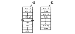
無線によって送信された前記パケットの信号は受信側の前記パケット通信システムにおいて、無線部1に備えられた受信部1aによって受信される。そこで、この受信された信号の受信電界強度S(n)が、電界強度検出器21によって、所定のサンプリング間隔(受信するパケットの時間長より十分短い時間間隔)で測定され、ディジタル値として検出される。そして、前記受信電界強度S(n)の値と、この受信電界強度S(n)が測定あるいは検出された時刻におけるカウンタ26のカウント値C1(n)とが制御回路(D)24によって、例えば図4の41あるいは42に示したようなデータ配列で連続的にメモリ27に格納され、記憶される。
【0019】
また、受信部1aによって受信されたパケットの受信信号は、復調器4によってディジタル復調された後、フラグ検出器22によってフラグの検出がおこなわれる。そして、フラグ検出器22がフレームの開始フラグを検出した時刻におけるカウンタ26のカウント値であるフレーム開始カウント値C2(m)と、フレームの終了フラグを検出した時刻におけるカウンタ26のカウント値であるフレーム終了カウント値C3(m)とが制御回路(E)25によって、C1(n)およびS(n)と同様のデータ配列で順次メモリ28に格納され、記憶される。
【0020】
以上に述べた通り、受信電界強度S(n)が測定あるいは検出された時刻と、フレームの開始フラグおよびフレームの終了フラグを検出した時刻とが、カウンタ26すなわち同じ一つの時計カウンタによって測定されるため、受信電界強度S(n)と1単位毎のパケット(フレーム)における受信開始時刻および受信終了時刻の各データが、同じ基準の時間測定によって時系列にメモリ27、28に記憶されることになるのである。
【0021】
一方、復調器4からパケット処理部6へ送られたパケットの受信信号は、1単位のパケット毎に正誤の検査が行われる。この検査結果に基づき、パケット判定器23によって、パケット到着番号rと、このパケットの正誤データN(r)とがメモリ29に格納され、記憶される。パケットの正誤データN(r)は例えばパケットが正しければ”1”、誤り(エラー)であれば”0”で表す。誤り(エラー)には、例えばフレームの長さが最小フレーム長より短かくて、無効フレームとなるような場合も含む。なお、パケット到着番号rはパケットが到着した順番に連続的に付されるシリアル番号である。
【0022】
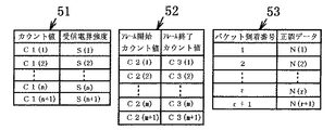
以上のようにして、メモリ27、28、29に記憶された各データは、所定のデータ量が蓄積された時点で、コンピュター7の記憶装置に転送される。コンピュータ7の記憶装置において、各データはカウント値C1(n)と受信電界強度S(n)とからなるレコード、フレーム開始カウント値C2(m)とフレーム終了カウント値C3(m)とからなるレコード、そしてパケット到着番号rとこのパケットの正誤データN(r)とからなるレコードに分類され、各レコードは例えば図5に示すテーブル51、テーブル52およびテーブル53のような構成で記憶されている。
【0023】
以上に述べた手順によって、カウント値C1(n)と受信電界強度S(n)、フレーム開始カウント値C2(m)とフレーム終了カウント値C3(m)、さらにパケット到着番号rとこれに対応するパケットの正誤データN(r)が併せて時系列にコンピュータ7の記憶装置に記憶される。
【0024】
次に、コンピュータ7の記憶装置に記憶された各データに基づきソフトウェアの処理によって、コンピュータ7のディスプレイ上に受信電界強度の波形と、パケットの時間長と、該パケットの正誤とがグラフ化される。以下にフレーム開始カウント値C2(m)、フレーム終了カウント値C3(m)、パケット到着番号rおよびパケットの正誤データN(r)の各データに基づいて、パケットの時間長と、該パケットの正誤とをグラフ化する処理について、図6に示したフローチャートを参照して説明する。
【0025】
まず、最初のデータを読み込むために変数m、パケット到着番号rの初期値を(1→m、1→r)のごとく代入(F1)してから、フレーム開始カウント値C2(m)とフレーム終了カウント値C3(m)とを読み取り、フレーム開始カウント値C2(m)を変数R1へ代入し、フレーム終了カウント値C3(m)を変数R2へ代入する(F2)。
【0026】
次いで、図7に示したように、コンピュータのディスプレイに表示した、カウント値すなわち時間をX軸とし、電界強度をY軸としたXY座標上に、カウント値R1からR2までを線分71として表示する(Y座標は任意とする)。このとき、パケット到着番号rのパケットの正誤をチェックし(F3)、例えば、正しい場合は青色、誤り(エラー)の場合は赤色として線分71の色を変えて表示する(F4、F5)。次にrをインクリメント(F6)した後、mをインクリメント(F7)していき、2番目のパケット(フレーム)、および3番目のパケット(フレーム)と、順次に前記した手順と同様に処理していく。以上の処理によって、パケットの時間長を線分71としてディスプレイのXY座標上に表示し、さらに該線分71をパケットの正誤によって色分けすることができるのである。
【0027】
受信電界強度については、図5のテーブル51に基づいて図7に示したように、前記XY座標上にカウント値C1(n)をX座標、受信電界強度S(n)をY座標としてプロットしていくことにより、受信電界強度を波形72として表示する(フローチャートには示さない)。
【0028】
上記のようにして、受信電界強度の波形と、パケットの時間長およびパケットの正誤とを、ディスプレイにおいてXY座標上に表示できるわけであるが、パケットの通信条件によっては、パケットを受信したときの受信電界強度の波形表示位置に対して、前記パケットの時間長の表示位置が、X軸(時間軸)上において、実際よりずれる場合がある。その理由は、パケットフレームのフラグの信号を受信部1aが受信したときの受信電界強度が電界強度検出器21によって測定あるいは検出される時刻と、前記フラグがフラグ検出器22によって検出される時刻との間に時間差が生じるためである。この時間差は、すなわち、フラグの信号が受信部1aに受信されてから、電界強度検出器21によって該フラグの信号の受信電界強度が測定あるいは検出されるまでの処理時間と、一方、フラグの信号が受信部1aに受信されてから、該フラグの信号が復調器4によって復調され、フラグ検出器22によってフラグとして検出されるまでの処理時間との差である。そして、この時間差分だけ、パケットが受信部1aに受信されたときにおける受信電界強度の波形と、前記パケットの時間長とが時間軸(X軸)上において、ずれて表示されるのである。
【0029】
従って、上記したような時間差が生じる場合には、この時間差分だけ補正して表示することにより、時間軸(X軸)上における受信電界強度の波形表示位置とパケットの時間長の表示位置とのずれをなくすことができる。
【0030】
上記した補正の具体的な方法は、例えば、パケットフレームのフラグの信号を受信部1aが受信したときの受信電界強度が、電界強度検出器21によって測定あるいは検出される時刻と、前記フラグがフラグ検出器22によって検出される時刻との時間差分に相当する、カウンタ26におけるカウント数を予め理論的あるいは実験的に求めておく。そして、例えば、フラグの信号が受信されたときの受信電界強度が電界強度検出器21によって測定あるいは検出される時刻より、前記フラグがフラグ検出器22によって検出される時刻の方が前記時間差分だけ遅い場合は、フレーム開始カウント値C2(m)とフレーム終了カウント値C3(m)とから前記時間差分に相当するカウント数を減算し、反対にフラグの信号が受信されたときの受信電界強度が電界強度検出器21によって測定あるいは検出される時刻より、前記フラグがフラグ検出器22によって検出される時刻の方が前記時間差分だけ早い場合は、カウント値C1(n)から前記時間差分に相当するカウント数を減算する。
【0031】
以上に記述した手順によって補正したカウント値のデータに基づいて、パケットの受信電界強度の波形と、パケットの時間長とを前述と同様の処理によって表示することにより、両者を一つの時間軸上にずれることなく、正確に、グラフによって表すことができる。
【0032】
なお、本発明のもう一つの実施形態として、前記パケット通信システムの構成において、フラグ検出器22の代わりに、データの透過性を保証したフレーム同期制御手段と、例えばSIO(シリアルインプットアウトプット)のようなLSIとを備えた変換器を用いることも可能である。すなわち、復調器4によりディジタル復調されたシリアルデータを、前記変換器がフレーム同期制御をおこないながら取り込む。次いで、前記シリアルデータをフレームのフラグを含めたまま、バイト単位(オクテット単位)のパラレルデータに変換した受信データとして出力し、該受信データが1単位毎に出力された時刻におけるカウンタ26のカウント値を検知し、該カウント値と前記受信データとを1単位のレコードとして、該レコードを順次、時系列にメモリに格納する。そして、ソフトウェアの処理により、前記レコードを、格納された順にチェックしていき、受信データがフレームのフラグと一致したレコードを判定し、該レコードのカウント値をフレーム開始カウント値またはフレーム終了カウント値と判定することができる。
【0033】
但し、前記変換器で受信データについて透過性を実現した後には、フレームの開始フラグと終了フラグとの間の受信データにフラグのコードと同じデータが存在している可能性があるため、フラグの判定を誤る場合がある。この場合、開始フラグと終了フラグとの間にフラグのコードと同じ受信データが出現した回数をカウントする手段を前記変換器の構成に備え、受信データの透過性を実現する処理(フラグコードと受信データとを区別するために挿入した”0”を除去する処理)をおこなうときに、開始フラグと終了フラグとの間にフラグのコードと同じ受信データが出現した回数を記憶し、前記ソフトウェアの処理において、レコードを順にチェックする際に、上記回数の分だけ、受信データとフラグの一致したレコードを見送ることにより、フラグの判定誤りを防ぐことができる。
【0034】
また、前記パケット通信システムの構成においては、前記変換器がフレーム同期制御をおこないながら取り込んだデータに基づいてフレームの正誤チェックをおこない、その正誤結果をメモリに記憶する機能を有するパケット検査手段を、パケット判定器23の代わりに、前記変換器に接続することも可能である。
【0035】
【発明の効果】
以上に述べてきたとおり、本発明によるパケット通信モニターによれば、受信したパケットの受信電界強度の波形と、パケットの時間長およびパケットの正誤とをグラフ化して一つの時間軸上に同時に表示することにより、パケットのエラー発生状況と受信電界強度を時系列にビジュアルな状態で比較してみることができる。従って、パケットがエラーをおこしやすくなる受信電界強度のレベルを認識したり、信号強度の大きいときと小さいときの平均的な周期を測定して最適なパケット長を推定することが、容易にかつ的確にできるのである。
【図面の簡単な説明】
【図1】本発明による一実施形態の全体の構成を示すブロック図である。
【図2】本発明におけるパケット通信モニター部分の一実施形態を示すブロック図である。
【図3】本発明において使用するフレーム構成の一例を示す図である。
【図4】本発明において各データをメモリに記憶した例を示す図である。
【図5】本発明においてコンピュータの記憶装置に各データを記憶する際のテーブルの例を示す図である。
【図6】本発明におけるパケットの時間長および正誤をグラフ化してディスプレイに表示する処理の流れを示すフローチャートである。
【図7】本発明によるパケット通信用モニターによって時系列に表示された受信電界強度の波形と、パケットの時間長および正誤とを表すグラフを示す図である。
【符号の説明】
1:無線部、1a:受信部、1b:送信部、2:TNC、3:モデム
4:復調器、5:変調器、6:パケット処理部、7:コンピュータ
A:モニター
21:電界強度検出器、22:フラグ検出器、23:パケット判定器
24:制御回路(D)、25:制御回路(E)、26:カウンタ(時計カウンタ)
27、28、29:メモリ、30:Iフレーム
41、42:メモリ内でのデータ配列例
51、52、53:コンピュータの記憶装置に記憶されたテーブル例
71:パケットの時間長を示す線分、72:受信電界強度の波形[0001]
[Industrial application fields]
The present invention relates to a packet communication monitor that displays in an easy-to-understand manner the relationship between the received electric field strength when receiving a packet, the packet length, and the correctness of the packet during wireless packet communication.
[0002]
[Prior art]
In recent wireless packet communications, for example, there is a remarkable progress in technology from the basic ALOHA system which is a basic packet communication system to application to a wireless LAN. By the way, in this wireless packet communication, it is always a problem that the unique characteristics of the wireless line, unlike the wired line, greatly affect the transmission characteristics. One of the problems is a phenomenon in which a communication state is good and a packet error is little and a time when an error frequently occurs alternately. The main cause is due to fading, which is a phenomenon in which the signal intensity changes irregularly with time.
[0003]
That is, when the signal strength is high (mountain) and the communication state is good, there are irregularly when the signal strength is small (valley) and the communication state is bad. Therefore, the relationship between the average rate of change and the packet length when the signal strength is large and small greatly affects the transmission characteristics of wireless packet communication.
[0004]
In other words, if the packet length is longer than the ratio of the average change in fading, it will always be included in the fading valley once during the transmission of one packet, and the packet will always have an error at that part. End up. On the other hand, if the packet length is short, the number of packets that do not encounter fading valleys increases, and communication becomes possible.
[0005]
Conventionally, in order to investigate the relationship between the error occurrence status of a packet and the fading as described above, first, the error occurrence status of the packet is analyzed by, for example, a line monitor, and the change in signal strength of the packet is received by, for example, reception. In general, the received electric field strength of a signal is measured by a signal strength measuring device (S meter) or the like, and then the analysis and measurement result of both are compared.
[0006]
That is, by monitoring the error occurrence status of the packet using a function such as a line monitor and observing the received electric field strength of the packet with an S meter or the like, the signal strength level at which the packet is likely to cause an error is recognized, The optimum packet length is estimated by measuring the average period when the signal strength is high and low.
[0007]
[Problems to be solved by the invention]
However, in the conventional investigation method described above, the relationship between the packet error occurrence status and the received electric field strength is difficult to represent by a visual display such as a graph, so the relationship between the packet error occurrence status and the received electric field strength is clearly recognized. There was ambiguity.
[0008]
An object of the present invention is to make it possible to visually display the error occurrence status of a packet and the state of the received electric field strength when investigating the relationship between the error occurrence status of the packet as described above and the received electric field strength. It is an object of the present invention to provide a packet communication monitor that can eliminate the ambiguity of the recognition of the reception state and can easily determine the reception state.
[0009]
[Means for Solving the Problems]
In order to achieve the above object, the present invention provides a packet communication monitor for use in a wireless packet communication system having a computer including a display, wherein the received electric field strength is time-series when receiving a packet transmitted wirelessly. , Means for storing the reception start time and reception end time of the packet, means for storing the correctness of the packet in time series, a waveform of the received electric field strength on the display of the computer and the packet there is provided a packet communication monitor characterized by comprising a means for displaying simultaneously sequence length and the correctness in the form of a graph.
[0010]
According to the packet communication monitor described above, the packet time length and the correctness of the packet can be displayed on the display on one time axis simultaneously with the waveform of the received electric field strength when the packet is received. And the received electric field strength can be easily recognized.
[0011]
DETAILED DESCRIPTION OF THE INVENTION
Hereinafter, an embodiment of the present invention will be described with reference to the accompanying drawings. The symbols m and n used in the detailed description of the present invention are variables that take natural numbers. The term “computer” means a general-purpose computer such as a personal computer.
[0012]
FIG. 1 shows the overall configuration of a packet communication system including a packet communication monitor according to the present invention. That is, the packet communication system includes a
[0013]
In the packet communication system, the
[0014]
The electric field strength detector 21 measures the received electric field strength of the received signal input to the receiving unit 1a at a predetermined sampling timing or a predetermined sampling interval, and the measurement data of the received electric field strength is obtained by, for example, an A / D converter. Means capable of detecting digital values are provided. The
[0015]
FIG. 3 is a diagram showing an example of a frame used in the packet communication system of the present invention. As shown in FIG. 3, the
[0016]
In the packet communication system, data transparency is guaranteed, and an error detection code employed in a frame check sequence (FCS) uses a CRC code system or the like. Further, the processing relating to the flag detection of the frame in the
[0017]
Next, the transmission / reception operation in the packet communication system including the packet communication monitor according to the present invention will be described below. First, in the packet communication system on the transmission side, data input to the computer 7 is assembled into a packet by the
[0018]
The signal of the packet transmitted by radio is received by the receiving unit 1a provided in the
[0019]
The received signal of the packet received by the receiving unit 1a is digitally demodulated by the
[0020]
As described above, the time when the received electric field strength S (n) is measured or detected and the time when the frame start flag and the frame end flag are detected are measured by the
[0021]
On the other hand, the received signal of the packet sent from the
[0022]
As described above, each data stored in the
[0023]
According to the above-described procedure, the count value C1 (n), the received electric field strength S (n), the frame start count value C2 (m), the frame end count value C3 (m), and the packet arrival number r and corresponding to this. The correct / incorrect data N (r) of the packet is also stored in the storage device of the computer 7 in time series.
[0024]
Next, the received electric field strength waveform, the packet time length, and the correctness of the packet are graphed on the display of the computer 7 by software processing based on each data stored in the storage device of the computer 7. . Hereinafter, based on each data of the frame start count value C2 (m), the frame end count value C3 (m), the packet arrival number r, and the packet correct / incorrect data N (r), the packet time length and the packet correct / incorrect The process of graphing the above will be described with reference to the flowchart shown in FIG.
[0025]
First, in order to read the first data, the variable m and the initial value of the packet arrival number r are substituted (F1) as (1 → m, 1 → r), then the frame start count value C2 (m) and the frame end The count value C3 (m) is read, the frame start count value C2 (m) is substituted into the variable R1, and the frame end count value C3 (m) is substituted into the variable R2 (F2).
[0026]
Next, as shown in FIG. 7, the count values R1 to R2 are displayed as
[0027]
As for the received electric field strength, as shown in FIG. 7 based on the table 51 of FIG. 5, the count value C1 (n) is plotted on the XY coordinates as the X coordinate and the received electric field strength S (n) is plotted as the Y coordinate. By doing so, the received electric field strength is displayed as a waveform 72 (not shown in the flowchart).
[0028]
As described above, the waveform of the received electric field intensity, the time length of the packet, and the correctness of the packet can be displayed on the XY coordinates on the display. However, depending on the communication conditions of the packet, The display position of the time length of the packet may deviate from the actual display position on the X axis (time axis) with respect to the waveform display position of the received electric field strength. The reason is that the received field strength when the reception unit 1a receives the flag signal of the packet frame is measured or detected by the field strength detector 21, and the time when the flag is detected by the
[0029]
Therefore, when the time difference as described above occurs, by correcting and displaying this time difference, the waveform display position of the received electric field intensity on the time axis (X axis) and the display position of the packet time length are displayed. Misalignment can be eliminated.
[0030]
The specific method of the correction described above includes, for example, the time when the reception field strength when the reception unit 1a receives the flag signal of the packet frame is measured or detected by the field strength detector 21, and the flag is the flag. The number of counts in the
[0031]
Based on the count value data corrected by the procedure described above, the waveform of the received electric field strength of the packet and the time length of the packet are displayed by the same processing as described above, so that both are on one time axis. It can be accurately represented by a graph without deviation.
[0032]
As another embodiment of the present invention, in the configuration of the packet communication system, instead of the
[0033]
However, after the transparency of the received data is realized by the converter, the same data as the flag code may exist in the received data between the start flag and the end flag of the frame. The judgment may be wrong. In this case, the converter is provided with means for counting the number of times the same received data as the flag code appears between the start flag and the end flag, and processing for realizing the transparency of the received data (flag code and reception The number of times that the received data that is the same as the code of the flag appears between the start flag and the end flag is stored between the start flag and the end flag when the “0” inserted to distinguish the data is performed. In this case, when checking the records in order, it is possible to prevent a flag determination error by seeing off the record in which the received data and the flag are matched by the number of times described above.
[0034]
Further, in the configuration of the packet communication system, a packet inspection unit having a function of performing a frame correctness check based on data captured by the converter while performing frame synchronization control, and storing a result of the correctness in a memory, Instead of the
[0035]
【The invention's effect】
As described above, according to the packet communication monitor of the present invention, the waveform of the received electric field strength of the received packet, the packet time length, and the packet correctness / incorrectness are graphed and displayed simultaneously on one time axis. Thus, it is possible to compare the error occurrence state of the packet and the received electric field strength in a visual state in time series. Therefore, it is easy and accurate to recognize the level of received field strength at which packets are prone to error, and to estimate the optimal packet length by measuring the average period when the signal strength is high and low. It can be done.
[Brief description of the drawings]
FIG. 1 is a block diagram showing the overall configuration of an embodiment according to the present invention.
FIG. 2 is a block diagram showing an embodiment of a packet communication monitor portion in the present invention.
FIG. 3 is a diagram showing an example of a frame configuration used in the present invention.
FIG. 4 is a diagram showing an example in which each data is stored in a memory in the present invention.
FIG. 5 is a diagram showing an example of a table when each data is stored in a storage device of a computer in the present invention.
FIG. 6 is a flowchart showing the flow of processing for graphing and displaying on a display the time length and correctness of a packet in the present invention.
FIG. 7 is a graph showing a waveform of a received electric field intensity displayed in time series by a packet communication monitor according to the present invention, and a packet time length and correctness.
[Explanation of symbols]
1: wireless unit, 1a: receiving unit, 1b: transmitting unit, 2: TNC, 3: modem 4: demodulator, 5: modulator, 6: packet processing unit, 7: computer A: monitor 21: electric field strength detector 22: Flag detector 23: Packet determiner 24: Control circuit (D) 25: Control circuit (E) 26: Counter (clock counter)
27, 28, 29: Memory, 30: I
Claims (1)
無線によって送信されるパケットを受信する際に受信電界強度を時系列に記憶する手段と、
前記パケットの受信開始時刻および受信終了時刻を記憶する手段と、
前記パケットの正誤を時系列に記憶する手段と、
コンピュータのディスプレイ上に前記受信電界強度の波形と前記パケットの長さおよび正誤とをグラフの形で同時系列に表示する手段と、
前記パケットのフラグの信号を受信したときの受信電界強度が検出される時刻と、前記フラグが検出される時刻との時間差分を補正し、前記受信電界強度の波形表示位置と前記パケットの時間長の表示位置との時間軸上のずれをなくす手段と、を備えたことを特徴とするパケット通信モニター。A packet communication monitor for use in a wireless packet communication system with a computer including a display,
Means for storing received electric field strength in time series when receiving a packet transmitted by radio;
Means for storing a reception start time and a reception end time of the packet;
Means for storing the correctness of the packet in time series;
Means for simultaneously displaying the waveform of the received electric field intensity and the length and correctness of the packet in the form of a graph on a computer display;
The time difference between the time when the received electric field strength when the packet flag signal is received and the time when the flag is detected is corrected, and the waveform display position of the received electric field strength and the time length of the packet are corrected. And a means for eliminating a shift on the time axis with respect to the display position of the packet communication monitor.
Priority Applications (2)
| Application Number | Priority Date | Filing Date | Title |
|---|---|---|---|
| JP2000197337A JP4365009B2 (en) | 2000-03-24 | 2000-05-27 | Packet communication monitor |
| US09/858,453 US6985495B2 (en) | 2000-05-27 | 2001-05-17 | Packet communication monitor |
Applications Claiming Priority (3)
| Application Number | Priority Date | Filing Date | Title |
|---|---|---|---|
| JP2000128614 | 2000-03-24 | ||
| JP2000-128614 | 2000-03-24 | ||
| JP2000197337A JP4365009B2 (en) | 2000-03-24 | 2000-05-27 | Packet communication monitor |
Publications (3)
| Publication Number | Publication Date |
|---|---|
| JP2001339473A JP2001339473A (en) | 2001-12-07 |
| JP2001339473A5 JP2001339473A5 (en) | 2006-08-10 |
| JP4365009B2 true JP4365009B2 (en) | 2009-11-18 |
Family
ID=26591037
Family Applications (1)
| Application Number | Title | Priority Date | Filing Date |
|---|---|---|---|
| JP2000197337A Expired - Fee Related JP4365009B2 (en) | 2000-03-24 | 2000-05-27 | Packet communication monitor |
Country Status (1)
| Country | Link |
|---|---|
| JP (1) | JP4365009B2 (en) |
Families Citing this family (4)
| Publication number | Priority date | Publication date | Assignee | Title |
|---|---|---|---|---|
| JP4683359B2 (en) | 2007-11-24 | 2011-05-18 | 健 星子 | Packet communication system |
| JP5121480B2 (en) * | 2008-02-01 | 2013-01-16 | 三菱電機株式会社 | Communication analysis apparatus and communication analysis method |
| ES2547408T3 (en) | 2008-02-01 | 2015-10-06 | Mitsubishi Electric Corporation | Communication analysis device and communication analysis method |
| JP6012510B2 (en) * | 2013-02-28 | 2016-10-25 | 株式会社日立製作所 | Wireless network system |
-
2000
- 2000-05-27 JP JP2000197337A patent/JP4365009B2/en not_active Expired - Fee Related
Also Published As
| Publication number | Publication date |
|---|---|
| JP2001339473A (en) | 2001-12-07 |
Similar Documents
| Publication | Publication Date | Title |
|---|---|---|
| US10083149B2 (en) | Method for serially transmitting a frame from a transmitter to at least one receiver and participants of a bus system via a bus system | |
| JPH02295323A (en) | Method and circuit equipment for detecting cell lacking and/or cell insersion when signal structured into cell form runs in cell adaptive transmitter | |
| CN108390752B (en) | Signal receiving method | |
| US20090292965A1 (en) | Method for transmitting wireless data and recording medium storing program for executing the method | |
| JP4365009B2 (en) | Packet communication monitor | |
| US11677581B2 (en) | Subscriber station for a serial bus system and method for communicating in a serial bus system | |
| WO2008004616A1 (en) | Estimation method, device, and program, and network measuring system | |
| CN116633813A (en) | Baud rate self-adaptive detection method and system for CAN bus | |
| CN101582738A (en) | Device and method for measuring frame error rate in transmission link | |
| US6985495B2 (en) | Packet communication monitor | |
| CN106941396A (en) | A kind of method of test Modbus communication qualities and slave station response performance | |
| JP4683359B2 (en) | Packet communication system | |
| JP5798383B2 (en) | Wireless communication method and apparatus | |
| JP3125756B2 (en) | Bit error rate measurement method | |
| JP4983435B2 (en) | Packet communication quality measuring apparatus and method | |
| US11581907B2 (en) | System and method for reception of wireless local area network packets with bit errors | |
| CN111158300B (en) | Data acquisition and reduction method | |
| JP2546370B2 (en) | Packet transfer characteristic measurement method | |
| JPH01132249A (en) | Start-stop synchronous system mode automatic setting system | |
| JP2667302B2 (en) | Cell synchronization method and packet communication device | |
| CN101123482A (en) | A device and method for testing sliding index in digital communication network | |
| CN115567939A (en) | Data integrity detection method, device, equipment and medium | |
| JP2669314B2 (en) | Data transfer device | |
| KR100528410B1 (en) | Synchronization Signal and Packet Status Information Control Device in High Level Data Link Control Communication | |
| KR100286757B1 (en) | Apparatus and method for acknowledging cell transfer between processors in an asynchronous transfer mode switch network |
Legal Events
| Date | Code | Title | Description |
|---|---|---|---|
| A521 | Written amendment |
Free format text: JAPANESE INTERMEDIATE CODE: A523 Effective date: 20060304 |
|
| A621 | Written request for application examination |
Free format text: JAPANESE INTERMEDIATE CODE: A621 Effective date: 20060304 |
|
| A521 | Written amendment |
Free format text: JAPANESE INTERMEDIATE CODE: A523 Effective date: 20060520 |
|
| A977 | Report on retrieval |
Free format text: JAPANESE INTERMEDIATE CODE: A971007 Effective date: 20080626 |
|
| A131 | Notification of reasons for refusal |
Free format text: JAPANESE INTERMEDIATE CODE: A131 Effective date: 20080708 |
|
| A521 | Written amendment |
Free format text: JAPANESE INTERMEDIATE CODE: A523 Effective date: 20080811 |
|
| A711 | Notification of change in applicant |
Free format text: JAPANESE INTERMEDIATE CODE: A711 Effective date: 20080811 |
|
| A521 | Written amendment |
Free format text: JAPANESE INTERMEDIATE CODE: A821 Effective date: 20080811 |
|
| A131 | Notification of reasons for refusal |
Free format text: JAPANESE INTERMEDIATE CODE: A131 Effective date: 20090127 |
|
| A521 | Written amendment |
Free format text: JAPANESE INTERMEDIATE CODE: A523 Effective date: 20090423 |
|
| A711 | Notification of change in applicant |
Free format text: JAPANESE INTERMEDIATE CODE: A711 Effective date: 20090423 |
|
| A521 | Written amendment |
Free format text: JAPANESE INTERMEDIATE CODE: A821 Effective date: 20090423 |
|
| TRDD | Decision of grant or rejection written | ||
| A01 | Written decision to grant a patent or to grant a registration (utility model) |
Free format text: JAPANESE INTERMEDIATE CODE: A01 Effective date: 20090804 |
|
| A01 | Written decision to grant a patent or to grant a registration (utility model) |
Free format text: JAPANESE INTERMEDIATE CODE: A01 |
|
| A61 | First payment of annual fees (during grant procedure) |
Free format text: JAPANESE INTERMEDIATE CODE: A61 Effective date: 20090820 |
|
| FPAY | Renewal fee payment (event date is renewal date of database) |
Free format text: PAYMENT UNTIL: 20120828 Year of fee payment: 3 |
|
| R150 | Certificate of patent or registration of utility model |
Free format text: JAPANESE INTERMEDIATE CODE: R150 |
|
| FPAY | Renewal fee payment (event date is renewal date of database) |
Free format text: PAYMENT UNTIL: 20130828 Year of fee payment: 4 |
|
| R250 | Receipt of annual fees |
Free format text: JAPANESE INTERMEDIATE CODE: R250 |
|
| R250 | Receipt of annual fees |
Free format text: JAPANESE INTERMEDIATE CODE: R250 |
|
| R250 | Receipt of annual fees |
Free format text: JAPANESE INTERMEDIATE CODE: R250 |
|
| R250 | Receipt of annual fees |
Free format text: JAPANESE INTERMEDIATE CODE: R250 |
|
| R250 | Receipt of annual fees |
Free format text: JAPANESE INTERMEDIATE CODE: R250 |
|
| LAPS | Cancellation because of no payment of annual fees |