JP4360471B2 - Cylinder head gasket - Google Patents
Cylinder head gasket Download PDFInfo
- Publication number
- JP4360471B2 JP4360471B2 JP2007036488A JP2007036488A JP4360471B2 JP 4360471 B2 JP4360471 B2 JP 4360471B2 JP 2007036488 A JP2007036488 A JP 2007036488A JP 2007036488 A JP2007036488 A JP 2007036488A JP 4360471 B2 JP4360471 B2 JP 4360471B2
- Authority
- JP
- Japan
- Prior art keywords
- bead
- cylinder head
- plate
- head gasket
- annular
- Prior art date
- Legal status (The legal status is an assumption and is not a legal conclusion. Google has not performed a legal analysis and makes no representation as to the accuracy of the status listed.)
- Expired - Fee Related
Links
Images


Description
本発明は、内燃機関のシリンダヘッドとシリンダブロック等の2部材の間に挟持されて、燃焼ガス等をシールするシリンダヘッドガスケットに関するものである。 The present invention relates to a cylinder head gasket that is sandwiched between two members such as a cylinder head and a cylinder block of an internal combustion engine and seals combustion gas and the like.
内燃機関のシリンダヘッドとシリンダブロックの間をシールするシリンダヘッドガスケットにおいては、シリンダボアに生じる高温・高圧の燃焼ガスのシールを行う必要があり、このシリンダボア用孔周りには、折り返し部、グロメット、ビード、ヘタリ防止部材、板厚調整部材等が配置された機械的強度及び耐久性に優れた金属製の積層型ガスケットが用いられている。 In a cylinder head gasket that seals between a cylinder head and a cylinder block of an internal combustion engine, it is necessary to seal high-temperature and high-pressure combustion gas generated in the cylinder bore. Around the cylinder bore hole, a folded portion, a grommet, a bead In addition, a metal laminated gasket having excellent mechanical strength and durability in which a settling prevention member, a plate thickness adjusting member, and the like are arranged is used.
このシリンダヘッドガスケットの一つとして、シリンダボア用孔の周りには、高温ガスが積層された金属基板の間に入り込まないように、金属基板(第1表面板)においてシリンダボア用孔の周縁部に折り返し部を設け、この折り返し部内に、シリンダボア用孔をシールするためのビード(内周側ビード)を有した円環状(リング状)のビードプレート(ビード板:中間板)を配置したり、板厚調整用の金属基板(第2表面板)を配置したりしているシリンダヘッドガスケットが提案されている(例えば、特許文献1参照。)。 As one of the cylinder head gaskets, the metal substrate (first surface plate) is folded around the cylinder bore hole around the cylinder bore hole so as not to enter between the stacked metal substrates. An annular (ring-shaped) bead plate (bead plate: intermediate plate) having a bead (inner peripheral side bead) for sealing the cylinder bore hole is disposed in the folded portion, and the plate thickness A cylinder head gasket in which an adjustment metal substrate (second surface plate) is arranged has been proposed (for example, see Patent Document 1).
このシリンダヘッドガスケットでは、ビードプレートに設けたビード(内周側ビード)によりシール面圧を高めてシリンダボア用孔の周囲にシールラインを形成し、また、板厚調整用の金属基板(第2表面板)を配置して折り返し部内の厚みを増加している。この厚み増加により折り返し部の曲げ部の曲率を大きくすることにより、この曲げ部の亀裂の発生を防止している。 In this cylinder head gasket, the seal surface pressure is increased by a bead (inner circumference side bead) provided on the bead plate to form a seal line around the cylinder bore hole, and a metal substrate for adjusting the plate thickness (Table 2). (Face plate) is arranged to increase the thickness in the folded portion. By increasing the curvature of the bent portion of the folded portion by increasing the thickness, the occurrence of cracks in the bent portion is prevented.
しかしながら、従来技術のビードプレートは、円環状に形成された一枚板の部品であり、シリンダヘッドガスケットの種類にもよるが、その板厚は0.2mm程度の比較的薄く、全体としては剛性も比較的小さいものである。そのため、取り扱いに細心の注意が必要な上に、シリンダボア用孔の周縁部に正確に配置する必要があるという問題がある。 However, the bead plate of the prior art is a single-plate component formed in an annular shape, and the plate thickness is relatively thin, about 0.2 mm, depending on the type of cylinder head gasket. Is relatively small. For this reason, there is a problem in that careful handling is required and it is necessary to arrange the cylinder bore hole accurately at the peripheral edge.
また、このビードブレートのビード周辺に、ヘタリ防止板や板厚調整板を配置する場合には、シリンダボア用孔の周縁部の折り返し部内に、これらの幾つかの部品を精度良く配置する必要があり、高い組付け技術が必要となるという問題がある。そのため、従来技術においては、ビードのヘタリ防止用のヘタリ防止板は配置されず、また、板厚調整は、表面板(金属基板)を折り返し部内に挿入して行うことが多く、金属基板の枚数の増加や重量の増加の要因の一つになっていた。
本発明は以上の問題点を解決するためになされたものであり、本発明の目的は、シリンダヘッドガスケットにおいて、シリンダボア用孔の周縁部の折り返し部内に配置される円環状のビード部材をヘタリ防止部材や板厚調整部材等との積層構造とすることにより、良好なシール性能を発揮できると共に、組み付け時の部品点数を減少して、軽量化と組み付け作業の簡便化を図ることができるシリンダヘッドガスケットを提供することにある。 The present invention has been made to solve the above-described problems, and an object of the present invention is to prevent an annular bead member disposed in a folded portion of a peripheral portion of a cylinder bore hole in a cylinder head gasket from being sticky. Cylinder head that can achieve good sealing performance by reducing the number of parts during assembly by reducing the number of parts during assembly by simplifying the assembly work by adopting a laminated structure with members, plate thickness adjustment members, etc. It is to provide a gasket.
上記の目的を達成するための本発明に係るシリンダヘッドガスケットは、内燃機関のシリンダヘッドとシリンダブロックの間に挟持されてシール機能を発揮し、金属基板と、該
金属基板のシリンダボア用孔の周縁部の折り返し部内に配置される円環状のビード部材とを有して構成されるシリンダヘッドガスケットにおいて、前記円環状のビード部材と円環状のヘタリ防止部材若しくは板厚調整部材若しくはビード板を一体化して形成した積層構造で構成される。
In order to achieve the above object, a cylinder head gasket according to the present invention is sandwiched between a cylinder head and a cylinder block of an internal combustion engine to exhibit a sealing function, and has a metal substrate and a peripheral edge of a cylinder bore hole in the metal substrate. In the cylinder head gasket configured to include an annular bead member disposed in the folded portion of the part, the annular bead member and the annular settling prevention member, the plate thickness adjusting member, or the bead plate are integrated. It is composed of a laminated structure formed by
従来技術においては、単に一枚板にビードを設けただけの円環状のビード部材を、本発明では、ヘタリ防止部材や板厚調整部材等との積層構造とすることにより、このビード部材に設けたビードのシール機能だけでなく、このビードのヘタリ防止やビード部材を配置した部位における板厚調整等の機能を持たせることができる。 In the prior art, an annular bead member in which a bead is simply provided on a single plate is provided in this bead member by adopting a laminated structure with a settling prevention member, a plate thickness adjusting member, etc. in the present invention. In addition to the function of sealing the bead, it is possible to provide functions such as prevention of settling of the bead and adjustment of the plate thickness at the portion where the bead member is disposed.
また、このビード部材はシリンダボア用孔の近傍のみに配置される円環状であるため、他の面積の広い金属基板に比べて、部品の大きさが小さく、剛性も比較的小さくなるため、比較的変形し易く取り扱いに注意が必要であったが、積層構造としているため、各金属基板の組み付け前に接着等により一体化したり、予め接着剤等で積層した板を加工することにより一体化した積層構造とすれば、部品点数も少なくなり、剛性が増し取り扱いが容易となる。そのため、組み付け作業も容易となり位置決めもより正確にできるようになる。 In addition, since this bead member is an annular shape disposed only in the vicinity of the cylinder bore hole, the size of the parts is small and the rigidity is relatively small compared to other metal substrates having a large area. It is easy to deform and care was required for handling, but because it has a laminated structure, it is integrated by bonding etc. before assembling each metal substrate, or integrated lamination by processing plates previously laminated with adhesive etc. With the structure, the number of parts is reduced, the rigidity is increased, and handling is facilitated. Therefore, the assembling work is facilitated and positioning can be performed more accurately.
上記のシリンダヘッドガスケットにおいて、前記円環状のビード部材を、該ビード部材に設けたビードの内周側又は外周側の一方又は両方に該ビード部材を折り曲げて形成した円環状のヘタリ防止部材、又は、該ビード部材に一体化された円環状のヘタリ防止部材を配設して形成すると、ビード部材のビードの片側又は両側にシム等のヘタリ防止部材が設けられるので、ビードに大きな押圧力が加わっても、このヘタリ防止部材が押圧力を負担してビードの平坦化を防止することができる。そのため、ビードのヘタリを防止し、ガスケットの耐久性を向上することができる。 In the above cylinder head gasket, the annular bead member is formed by bending the bead member on one or both of the inner peripheral side and the outer peripheral side of the bead provided on the bead member, or If an annular settling prevention member integrated with the bead member is disposed, a settling prevention member such as a shim is provided on one side or both sides of the bead of the bead member, so that a large pressing force is applied to the bead. However, the anti-sticking member can bear the pressing force and prevent the bead from being flattened. For this reason, it is possible to prevent the beads from becoming loose and to improve the durability of the gasket.
上記のシリンダヘッドガスケットにおいて、前記円環状のビード部材を、該ビード部材に設けたビードの凹側に該ビード部材を折り曲げて形成した板厚調整部材、又は、該ビード部材に一体化された円環状の板厚調整部材を配設して形成すると、この構成によりビードの凹側に板厚調整部材を配置することができるので、ビード部材1個でシール機能と板厚調整の機能を合せ持つことになる。この板厚調整は、従来技術では、折り返し部を有する金属基盤ともビード部材とも異なる別の金属基板を用いていたので、本発明では、部品点数を減少でき、軽量化にも寄与することができる。 In the above cylinder head gasket, the annular bead member is formed by bending the bead member on the concave side of the bead provided on the bead member, or a circle integrated with the bead member. If an annular plate thickness adjusting member is provided and formed, this configuration allows the plate thickness adjusting member to be disposed on the concave side of the bead, so that one bead member has both a sealing function and a plate thickness adjusting function. It will be. In the prior art, this metal thickness adjustment uses another metal substrate that is different from the metal substrate having the folded portion and the bead member. Therefore, in the present invention, the number of parts can be reduced and the weight can be reduced. .
上記のシリンダヘッドガスケットにおいて、前記円環状のビード部材を、外側に凸となるビードを該ビード部材を折り曲げて表裏の両側に形成するか、又は、外側に凸となるビードを有する円環状のビード板を一体化して形成すると、この構成により、1個のビード部材でビードを2つ設けられるので、強いシールラインを形成できる。なお、これらのビードは、互いに重なり合う位置関係で形成すると強い面圧を発生でき、互いに重なり合わない位置関係で形成すると二重のシールラインを形成できる。 In the above cylinder head gasket, the annular bead member is formed on both sides of the front and back by bending the bead member to be outwardly convex, or the annular bead having an outwardly convex bead. When the plates are integrated and formed, two beads can be provided by one bead member by this configuration, so that a strong seal line can be formed. These beads can generate a strong surface pressure when they are formed so as to overlap each other, and a double seal line can be formed when they are formed so as not to overlap each other.
そして、上記のシリンダヘッドガスケットにおいて、ビード部材を、一枚の板を折り返して積層構造に形成すると、積層構造を構成する板がバラバラになることが無いので、取り扱いが非常に簡便になる。また、積層構造内での各部材間の位置決めが不要になるので工作性が著しく向上する。 In the cylinder head gasket, when the bead member is formed in a laminated structure by folding a single plate, the plates constituting the laminated structure do not fall apart, so that handling becomes very simple. Further, since the positioning between the members in the laminated structure is not necessary, the workability is remarkably improved.
本発明のシリンダヘッドガスケットによれば、シリンダボア用孔の周縁部の折り返し部内に配置されるビード部材を積層構造で形成したので、ビードのシール性能の他に、各積層部分の面圧調整や板厚調整等の作用効果を発揮できるようになり、また、軽量化を図ることができる。更に、ビード部材の積層構造を組み付け前に一体化すると、組み付け時の部品点数が減少すると共に、ビード部材の剛性が増すので組み付け作業を簡便化でき、製造コストを低く抑えることができる。 According to the cylinder head gasket of the present invention, since the bead member disposed in the folded portion at the peripheral edge of the cylinder bore is formed in a laminated structure, in addition to the bead sealing performance, the surface pressure adjustment and plate of each laminated portion The effects such as thickness adjustment can be exhibited, and the weight can be reduced. Further, when the laminated structure of the bead members is integrated before assembling, the number of parts at the time of assembling is reduced and the rigidity of the bead members is increased, so that the assembling work can be simplified and the manufacturing cost can be kept low.
また、ビード部材の積層構造を一枚の板を折り返して形成すると、ビード部材における積層に際しての位置決めが不要になるので、工作性が著しく向上する。 Further, if the laminated structure of the bead members is formed by folding a single plate, positioning during the lamination of the bead members is not necessary, so that the workability is remarkably improved.
次に、図面を参照して本発明の実施の形態のシリンダヘッドガスケットについて説明する。なお、図1〜図11は、模式的な説明図であり、理解し易いように、各金属基板の板厚やビードの寸法及び縦横比も実際のものとは異ならせて表示している。 Next, a cylinder head gasket according to an embodiment of the present invention will be described with reference to the drawings. 1 to 11 are schematic explanatory diagrams, and for easy understanding, the plate thickness, bead size, and aspect ratio of each metal substrate are displayed differently from the actual ones.
図1〜図8に示すように、本発明の実施の形態のシリンダヘッドガスケット1A〜1Hは、エンジン(内燃機関)のシリンダヘッドとシリンダブロック(シリンダボディ)との間に挟まれて、燃焼ガスや冷却水や潤滑オイル等をシールするガスケットである。 As shown in FIGS. 1 to 8, cylinder head gaskets 1 </ b> A to 1 </ b> H according to an embodiment of the present invention are sandwiched between a cylinder head of an engine (internal combustion engine) and a cylinder block (cylinder body), and combustion gas It is a gasket that seals cooling water and lubricating oil.
このシリンダヘッドガスケット1A〜1Hは、第1金属基板(第1表面板)10と第2金属基板(第2表面板)20とビード部材30A〜30Hと中間板40(,50)を有して構成される。この第1金属基板(第1表面板)10と第2金属基板(第2表面板)20は、比較的柔らかくてなじみ易い材料である軟鋼板やステンレス焼鈍材等で形成され、ビード部材30A〜30Hと中間板40(,50)は硬質で比較的強いバネ鋼板(スプリング鋼板)などで形成される。
The
この第1表面板10のシリンダボア用孔2の周縁部において、第2表面板20側に折り返して曲がり部11を介して折り返し部(フランジ部)12を設ける。この第1折り返し部12の内側、即ち、この折り返し部12と第1表面板10との間に、ビード(フルビード)31(,35)を有すると共に積層構造を持つ円環状のビード部材30A〜30Hを配置し、このビード部材30A〜30Hに設けたビード31(,35)により、シリンダボア用孔2の周囲にシール面圧が高いシールラインを形成する。
At the peripheral edge portion of the
一方、この第1金属基板10の折り返し部12の外周側に内周縁を有する第2金属基板20を配置する。この第2金属基板20と第1金属基板10との間に、ハーフビード41(,51)を有する中間板40(,50)を配置する。これにより、シリンダヘッド又はシリンダブロックに当接する側において、第1金属基板10の折り返し部12側の表面と第2金属基板20の表面とを略同じレベルにする。このハーフビード41(,51)は、ビード部材30A〜30Hの外周側を囲む第1平坦部と、この第1平坦部の外周側に隣接する斜面部と、この斜面部の外周側に隣接する第2平坦部を有して形成される。
On the other hand, a
そして、図1〜図3に示すように、第1の実施の形態のシリンダヘッドガスケット1A〜1Cにおいては、ビード部材30A〜30Cを、ビード31の両側又は内周側又は外周側に板状のヘタリ防止部材32,33を設けて形成する。このヘタリ防止部材32,33は大きな押圧力が加わってビード31が大きく変形する時に、ビード31に加わる押圧力を分担して、ビードの平坦化を防止する。これにより、ビード31のヘタリを防止することができるので、シリンダヘッドガスケット1A〜1Cの耐久性を向上することができる。
As shown in FIGS. 1 to 3, in the cylinder head gaskets 1 </ b> A to 1 </ b> C according to the first embodiment, the bead members 30 </ b> A to 30 </ b> C are plate-like on both sides, the inner peripheral side, or the outer peripheral side of the
この積層構造は、図1〜図3では、一枚の円環状のビード部材30A〜30Cの内周側と外周側の両方又は一方を折り返して形成しているが、図9〜図11に示すように、ヘタリ防止板(面圧調整板)32’,33’をビード31の板30A’〜30C’とは別体で形成してこれらを積層することにより積層構造としてもよい。この場合は、シリンダヘッドガスケット1A〜1Cの組み付け前に、ヘタリ防止板32’,33’とビード31を有する板30A’〜30C’とを接着剤等で張り付けて一体化して、ビード部材30A〜30Cを積層構造にしておくことが、部品点数の減少の面と位置決め精度の面と作業性の面等から好ましい。
1 to 3, the laminated structure is formed by folding back one or both of the inner peripheral side and the outer peripheral side of one
次に第2の実施の形態について説明する。この第2の実施の形態のシリンダヘッドガスケット1D〜1Fは、ビード31の凹側に平坦部である板厚調整部材34を設けてビード部材30D〜30Fを形成する。この板厚調整部材34は、図4に示すように、ビード部材30Dの外周側を折り返して形成したり、図5に示すように、ビード部材30Eの内周側を折り返して形成したりする。また、図6に示すように、更に、ヘタリ防止部材32を有してビード部材30Fを形成してもよい。
Next, a second embodiment will be described. In the
なお、この板厚調整部材34は、図4〜図6では、一枚の円環状のビード部材の内周側と外周側の両方又は一方を折り返して形成しているが、板厚調整部材34をビード31の板とは別体の板等で形成してこれらを積層することにより積層構造(図示しない)としてもよい。この場合は、シリンダヘッドガスケット1D〜1Fの組み付け前に、この別体の板厚調整部材34とビード31を有する板とを接着剤等で張り付けて一体化して、ビード部材30D〜30Fを積層構造にしておくことが、部品点数の減少の面等から好ましい。
4 to 6, the plate
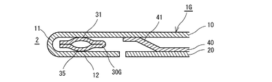
次に第3の実施の形態について説明する。図7に示すように、この第3の実施の形態のシリンダヘッドガスケット1Gは、外側に凸となるビード31,35を表裏の両側に設けてビード部材30Gを形成する。この構成の場合には、1個のビード部材30Gで外側に凸となるビードが2つ設けられるので、より強いシールラインを形成できる。これらのビードは、図7及び図8に示すように、互いに重なり合う位置関係で形成すると強いシール面圧を発生でき、また、図示しないが、互いに重なり合わない位置関係で形成すると二重のシールラインを形成できる。なお、図示していないが、図1〜図3のヘタリ防止部材31,32を設ける構成を追加すれば、ヘタリ防止部材31,32による作用効果も同時に発揮することができるようになる。
Next, a third embodiment will be described. As shown in FIG. 7, in the
図7では、これらのビード31,35を、一枚の円環状のビード部材の外周側を折り返して形成しているが、内周側を折り返して形成してもよく、また、第2のビード35をビード31の板とは別の板で形成してこれらを積層することにより積層構造(図示しない)としてもよい。この場合は、シリンダヘッドガスケット1Gの組み付け前に、この別体の第2のビード35を有する板とビード31を有する板とを接着剤等で張り付けて一体化して、ビード部材30Gを積層構造にしておくことが、部品点数の減少の面から好ましい。
In FIG. 7, these
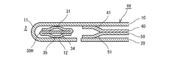
次に第4の実施の形態について説明する。図8に示すように、この第4の実施の形態のシリンダヘッドガスケット1Hは、外側に凸となるビード31,35を表裏の両側に設けると共に、このビード31,35の間に平坦部で形成される板厚調整部材34を設けてビード部材30Hを形成する。この構成の場合には、1個のビード部材30Hで外側に凸となるビード31,35が2つ設けられるので、より強いシールラインを形成できると共に、板厚調整部材34により、シリンダヘッドガスケット1Hの板厚を調整できる。
Next, a fourth embodiment will be described. As shown in FIG. 8, the
また、このように表裏の両側にビード31,35を備えると、シリンダヘッドガスケット1Hの全体の板厚が大きくなるので、ハーフビード51を持つ中間板50を、中間板40と第2表面板20の間に配置してこの部分の板厚を調整する。なお、図示していないが、図1〜図3のヘタリ防止部材32,33を設ける構成を追加すれば、ヘタリ防止部材32,33による作用効果も同時に発揮することができるようになる。
In addition, when the
この積層構造のビード部材30Hは、板厚調整部材となる平坦部の内周側と外周側において折り返し後に外側に凸となるビード31,35をそれぞれ設けて、それぞれ折り返して互いに逆の面に積層することで形成することができる。また、第2のビード35、板厚調整部材34、ビード31の板とをそれぞれ別の板で形成してこれらを積層することにより積層構造(図示しない)としてもよい。この場合は、シリンダヘッドガスケット1Hの組み付け前に、この別体の第2のビード35を有する板と板厚調整部分34となる板と、ビード31を有する板とを接着剤等で張り付けて一体化して、ビード部材30Hを積層構造にしておくことが、部品点数の減少の面等から好ましい。
The
上記の構造の第1から第3の実施の形態のシリンダヘッドガスケット1A〜1Hによれば、従来技術においては、単にビードを設けただけの一枚板の円環状のビード部材を、本発明では積層構造とすることにより、ビードのシール機能に加えて、このビードのヘタリを防止する機能やガスケットの板厚を調整する機能を持たせることができる。
According to the
更に、この積層構造のビード部材を、各金属基板を組み合わせる前に、複数枚の板状部材を接着等によって一個のビード部材に一体化しておくと、剛性が増すので取り扱いが容易となる上に更に部品点数が減少するので組みつけが容易となる。また、一枚板を折り返し加工して積層構造のビード部材を形成すると、分離することが無いのでより取り扱いが容易となる。 In addition, if a plurality of plate-like members are integrated into one bead member by bonding or the like before combining the metal substrates, the laminated structure of the bead member can be handled easily because the rigidity is increased. Furthermore, since the number of parts is reduced, assembly becomes easy. Further, when a single-plate is folded to form a bead member having a laminated structure, it is easier to handle because it is not separated.
これらのシリンダヘッドガスケット1A〜1Hの具体的な寸法は、エンジンによって異なるが、例えば、第1金属基板10と第2金属基板20の板厚は、それぞれ0.2〜0.8mm程度と0.2〜0.4mm程度であり、ビード部材30A〜30Hを折り返し構造で形成する時の一枚の板厚と中間板40(,50)の板厚は、それぞれ0.2〜0.4mm程度と0.2〜0.4mm程度である。また、ビード31、35とハーフビード41,51の高さは0.1〜0.5mm程度であるが、シールすべき燃焼ガスの圧力等の要因によって、ビード31,35やハーフビード41,51の形状や寸法等は適切なシール面圧や耐久性が得られるように調整して設計される。
Although the specific dimensions of these
1A〜1H シリンダヘッドガスケット
2 シリンダボア用孔
11 曲げ部
12 折り返し部(フランジ部)
10 第1金属基板(第1表面板)
20 第2金属基板(第2表面板)
30A〜30H ビード部材
31,35 ビード
32,33 ヘタリ防止部材(面圧調整部材)
32’,33’ ヘタリ防止板(面圧調整板)
34 板厚調整部材
40,50 中間板
41,51 ハーフビード
1A to 1H
10 First metal substrate (first surface plate)
20 Second metal substrate (second surface plate)
30A-
32 ', 33' Anti-sticking plate (surface pressure adjusting plate)
34 Plate
Claims (5)
Priority Applications (1)
| Application Number | Priority Date | Filing Date | Title |
|---|---|---|---|
| JP2007036488A JP4360471B2 (en) | 2007-02-16 | 2007-02-16 | Cylinder head gasket |
Applications Claiming Priority (1)
| Application Number | Priority Date | Filing Date | Title |
|---|---|---|---|
| JP2007036488A JP4360471B2 (en) | 2007-02-16 | 2007-02-16 | Cylinder head gasket |
Publications (2)
| Publication Number | Publication Date |
|---|---|
| JP2008202422A JP2008202422A (en) | 2008-09-04 |
| JP4360471B2 true JP4360471B2 (en) | 2009-11-11 |
Family
ID=39780199
Family Applications (1)
| Application Number | Title | Priority Date | Filing Date |
|---|---|---|---|
| JP2007036488A Expired - Fee Related JP4360471B2 (en) | 2007-02-16 | 2007-02-16 | Cylinder head gasket |
Country Status (1)
| Country | Link |
|---|---|
| JP (1) | JP4360471B2 (en) |
Families Citing this family (1)
| Publication number | Priority date | Publication date | Assignee | Title |
|---|---|---|---|---|
| JP5801080B2 (en) | 2011-03-30 | 2015-10-28 | ニチアス株式会社 | Cylinder head gasket |
-
2007
- 2007-02-16 JP JP2007036488A patent/JP4360471B2/en not_active Expired - Fee Related
Also Published As
| Publication number | Publication date |
|---|---|
| JP2008202422A (en) | 2008-09-04 |
Similar Documents
| Publication | Publication Date | Title |
|---|---|---|
| JP2007139177A (en) | Gasket | |
| JP2009097528A (en) | Metal gasket | |
| JP2008202625A (en) | Laminated gasket | |
| EP1108925A2 (en) | Metallic Gasket | |
| JPH0536136Y2 (en) | ||
| KR20060096304A (en) | Steel laminate cylinder head gasket | |
| KR100917805B1 (en) | Steel laminate gasket | |
| JP2008202751A (en) | Cylinder head gasket | |
| JP2587785Y2 (en) | Metal laminated gasket with embossed part | |
| JP5077436B2 (en) | Cylinder head gasket | |
| JP4360471B2 (en) | Cylinder head gasket | |
| JP3811700B2 (en) | Metal laminated gasket | |
| JP2005226806A (en) | Cylinder head gasket | |
| US8342537B2 (en) | Metal laminate gasket | |
| JP4056503B2 (en) | Metal gasket | |
| JP4541399B2 (en) | Metal gasket | |
| JP2007309344A (en) | Cylinder head gasket | |
| JP2009191870A (en) | Metal gasket | |
| JP5729353B2 (en) | Cylinder head gasket | |
| JP2010203509A (en) | Metal laminate type cylinder head gasket | |
| JP3840475B2 (en) | Cylinder head gasket | |
| JP2005133815A (en) | Metal laminated type gasket | |
| JP2000227047A (en) | Metallic gasket | |
| JP2973118B2 (en) | Metal plate laminated gasket | |
| JP2017190834A (en) | gasket |
Legal Events
| Date | Code | Title | Description |
|---|---|---|---|
| A977 | Report on retrieval |
Free format text: JAPANESE INTERMEDIATE CODE: A971007 Effective date: 20090108 |
|
| A131 | Notification of reasons for refusal |
Free format text: JAPANESE INTERMEDIATE CODE: A131 Effective date: 20090203 |
|
| A521 | Written amendment |
Free format text: JAPANESE INTERMEDIATE CODE: A523 Effective date: 20090406 |
|
| A131 | Notification of reasons for refusal |
Free format text: JAPANESE INTERMEDIATE CODE: A131 Effective date: 20090512 |
|
| A521 | Written amendment |
Free format text: JAPANESE INTERMEDIATE CODE: A523 Effective date: 20090618 |
|
| TRDD | Decision of grant or rejection written | ||
| A01 | Written decision to grant a patent or to grant a registration (utility model) |
Free format text: JAPANESE INTERMEDIATE CODE: A01 Effective date: 20090728 |
|
| A01 | Written decision to grant a patent or to grant a registration (utility model) |
Free format text: JAPANESE INTERMEDIATE CODE: A01 |
|
| A61 | First payment of annual fees (during grant procedure) |
Free format text: JAPANESE INTERMEDIATE CODE: A61 Effective date: 20090804 |
|
| R150 | Certificate of patent or registration of utility model |
Ref document number: 4360471 Country of ref document: JP Free format text: JAPANESE INTERMEDIATE CODE: R150 Free format text: JAPANESE INTERMEDIATE CODE: R150 |
|
| FPAY | Renewal fee payment (event date is renewal date of database) |
Free format text: PAYMENT UNTIL: 20120821 Year of fee payment: 3 |
|
| FPAY | Renewal fee payment (event date is renewal date of database) |
Free format text: PAYMENT UNTIL: 20130821 Year of fee payment: 4 |
|
| R250 | Receipt of annual fees |
Free format text: JAPANESE INTERMEDIATE CODE: R250 |
|
| FPAY | Renewal fee payment (event date is renewal date of database) |
Free format text: PAYMENT UNTIL: 20130821 Year of fee payment: 4 |
|
| FPAY | Renewal fee payment (event date is renewal date of database) |
Free format text: PAYMENT UNTIL: 20130821 Year of fee payment: 4 |
|
| FPAY | Renewal fee payment (event date is renewal date of database) |
Free format text: PAYMENT UNTIL: 20130821 Year of fee payment: 4 |
|
| R250 | Receipt of annual fees |
Free format text: JAPANESE INTERMEDIATE CODE: R250 |
|
| R250 | Receipt of annual fees |
Free format text: JAPANESE INTERMEDIATE CODE: R250 |
|
| R250 | Receipt of annual fees |
Free format text: JAPANESE INTERMEDIATE CODE: R250 |
|
| R250 | Receipt of annual fees |
Free format text: JAPANESE INTERMEDIATE CODE: R250 |
|
| R250 | Receipt of annual fees |
Free format text: JAPANESE INTERMEDIATE CODE: R250 |
|
| R250 | Receipt of annual fees |
Free format text: JAPANESE INTERMEDIATE CODE: R250 |
|
| LAPS | Cancellation because of no payment of annual fees |