JP2017190834A - gasket - Google Patents
gasket Download PDFInfo
- Publication number
- JP2017190834A JP2017190834A JP2016080867A JP2016080867A JP2017190834A JP 2017190834 A JP2017190834 A JP 2017190834A JP 2016080867 A JP2016080867 A JP 2016080867A JP 2016080867 A JP2016080867 A JP 2016080867A JP 2017190834 A JP2017190834 A JP 2017190834A
- Authority
- JP
- Japan
- Prior art keywords
- seal plate
- bead
- plate
- hole
- gasket
- Prior art date
- Legal status (The legal status is an assumption and is not a legal conclusion. Google has not performed a legal analysis and makes no representation as to the accuracy of the status listed.)
- Pending
Links
Images
Landscapes
- Gasket Seals (AREA)
Abstract
【課題】ガスケットのシール性を効果的に向上させる。【解決手段】下側シールプレート11と、下側シールプレート11の上面に積層された中間プレート13と、中間プレート13の上面に積層されたシム部材14と、シム部材14の上面から下側シールプレート11の下面に折り返されて、下側シールプレート11の貫通孔11Aの周縁、中間プレート13の貫通孔13Aの周縁及び、シム部材14の貫通孔の周縁を覆うグロメット構造20を有する上側シールプレート12と、下側シールプレート11に中間プレート13とは反対側に突出して形成された下側ビード16と、上側シールプレート12に下側ビード16と同方向に突出して形成された上側ビード15とを備える。【選択図】図2An object of the present invention is to effectively improve the sealing performance of a gasket. A lower seal plate, an intermediate plate laminated on the upper surface of the lower seal plate, a shim member laminated on the upper surface of the intermediate plate, and a lower seal from the upper surface of the shim member. An upper seal plate having a grommet structure 20 that is folded back to the lower surface of the plate 11 and covers the periphery of the through hole 11A of the lower seal plate 11, the periphery of the through hole 13A of the intermediate plate 13, and the periphery of the through hole of the shim member 14. 12, a lower bead 16 formed on the lower seal plate 11 so as to protrude on the opposite side of the intermediate plate 13, and an upper bead 15 formed on the upper seal plate 12 so as to protrude in the same direction as the lower bead 16. Is provided. [Selection] Figure 2
Description
本発明は、ガスケットに関し、特に、複数枚のシールプレートを備える積層型のガスケットに関する。 The present invention relates to a gasket, and more particularly to a laminated gasket including a plurality of seal plates.
従来より、エンジンのシリンダブロックとシリンダヘッドとの間に介装されて、これらシリンダブロックとシリンダヘッドとの隙間をシールする積層型のシリンダヘッドガスケットが実用化されている。 2. Description of the Related Art Conventionally, a laminated cylinder head gasket that is interposed between an engine cylinder block and a cylinder head and seals a gap between the cylinder block and the cylinder head has been put into practical use.
シリンダブロックとシリンダヘッドとの隙間は燃焼室内の爆発力等の影響により変化するため、高いシール性を維持するには、シールプレートの所定箇所にシリンダブロックやシリンダヘッドの動きに追従して変形するビードを設ける必要がある。また、燃焼ガスが各シールプレートの層間から漏出することを防止するには、各シールプレートの燃焼室を形成する部位を覆うグロメットを設ける必要がある。 Since the gap between the cylinder block and the cylinder head changes due to the impact of the explosive force in the combustion chamber, in order to maintain high sealing performance, the cylinder plate and cylinder head are deformed following the movement of the cylinder block and cylinder head in order to maintain high sealing performance. It is necessary to provide a bead. Further, in order to prevent the combustion gas from leaking out between the layers of each seal plate, it is necessary to provide a grommet that covers a portion of each seal plate that forms the combustion chamber.
例えば、特許文献1には、積層された三枚のシールプレートのうち、最上層シールプレートの先端側を最下層シールプレートの下面に折り返してグロメットを形成すると共に、最下層シールプレートに下方に突出する下側ビードを設け、さらに中間層シールプレートに上方に突出する上側ビードを設けた構造が開示されている。
For example, in
一般的に、シリンダヘッドはシリンダブロックの上部に複数本のヘッドボルトを強く締め付けることにより固定される。このため、例えば、特許文献1記載の構造では、上側ビードがシリンダヘッドに強く押圧されて全屈することになる。その結果、上側ビードにへたりが生じて復元力を失うと、特にシリンダブロックとシリンダヘッドとの隙間が大きくなる最高筒内圧時は、上側ビードがシリンダブロックやシリンダヘッドの動きに追従できなくなり、シール性を十分に確保できなくなる可能がある。
Generally, the cylinder head is fixed by strongly tightening a plurality of head bolts on the upper part of the cylinder block. For this reason, for example, in the structure described in
開示の技術は、ガスケットのシール性を効果的に向上させることを目的とする。 The disclosed technique aims to effectively improve the sealing performance of the gasket.
開示の技術は、第1貫通孔を有する下側シールプレートと、前記第1貫通孔と同心の第2貫通孔を有すると共に、前記下側シールプレートの上面に積層された中間プレートと、前記第1及び前記第2貫通孔と同心の第3貫通孔を有すると共に、前記中間プレートの上面に積層されたシム部材と、前記シム部材の上面から前記下側シールプレートの下面に折り返されて、前記第1貫通孔の周縁、前記第2貫通孔の周縁及び、前記第3貫通孔の周縁を覆うグロメット構造を有する上側シールプレートと、前記下側シールプレートに前記中間プレートとは反対側に突出して形成された下側ビードと、前記上側シールプレートに前記下側ビードと同方向に突出して形成された上側ビードと、を備えることを特徴とする。 The disclosed technology includes a lower seal plate having a first through hole, a second through hole concentric with the first through hole, an intermediate plate stacked on an upper surface of the lower seal plate, 1 and a third through hole concentric with the second through hole, a shim member stacked on the upper surface of the intermediate plate, and folded back from the upper surface of the shim member to the lower surface of the lower seal plate, An upper seal plate having a grommet structure covering the periphery of the first through hole, the periphery of the second through hole, and the periphery of the third through hole, and the lower seal plate projecting to the opposite side of the intermediate plate And a lower bead formed on the upper seal plate so as to protrude in the same direction as the lower bead.
前記下側ビードが前記グロメット構造よりも外側の前記下側シールプレートに形成され、前記上側ビードが前記シム部材よりも外側の前記上側シールプレートに形成されてもよい。 The lower bead may be formed on the lower seal plate outside the grommet structure, and the upper bead may be formed on the upper seal plate outside the shim member.
前記上側シールプレートが前記シム部材を介することなく前記中間プレートの上面に積層され、前記グロメット構造が前記上側シールプレートと別体に形成されると共に、前記上側シールプレートの上面から前記下側シールプレートの下面に折り返され、前記上側ビードが前記上側シールプレートに前記下側ビードとは反対側に突出して形成されてもよい。 The upper seal plate is laminated on the upper surface of the intermediate plate without the shim member, and the grommet structure is formed separately from the upper seal plate, and from the upper surface of the upper seal plate to the lower seal plate The upper bead may be formed on the upper seal plate so as to protrude to the opposite side of the lower bead.
開示の技術によれば、ガスケットのシール性を効果的に向上させることができる。 According to the disclosed technology, the sealing performance of the gasket can be effectively improved.
以下、添付図面に基づいて、本発明の一実施形態に係るガスケットについて説明する。同一の部品には同一の符号を付してあり、それらの名称および機能も同じである。したがって、それらについての詳細な説明は繰返さない。 Hereinafter, a gasket according to an embodiment of the present invention will be described with reference to the accompanying drawings. The same parts are denoted by the same reference numerals, and their names and functions are also the same. Therefore, detailed description thereof will not be repeated.
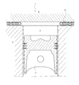
図1は、本実施形態のガスケット10が適用されたエンジン1の一部を示す模式的な縦断面図である。シリンダブロック2のシリンダボア3内には、ピストン4が往復移動可能に収容されている。シリンダブロック2の上部には、シリンダヘッド5が本実施形態のガスケット10を介して図示しない複数本のヘッドボルトにより締結固定されている。
FIG. 1 is a schematic longitudinal sectional view showing a part of an
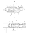
次に、図2に基づいて、本実施形態に係るガスケット10の詳細構成について説明する。図2(A)はガスケット10の締め付け前の状態、図2(B)はガスケット10の締め付け後の状態を示す模式的な断面図である。
Next, based on FIG. 2, the detailed structure of the
図2に示すように、本実施形態のガスケット10は、三枚のプレート部材を積層したもので、シリンダブロック2側の下側シールプレート11と、シリンダヘッド5側の上側シールプレート12と、これら下側及び上側シールプレート11,12の間に設けられた中間プレート13と、シリンダボア3よりも大径の円環状に形成されたシム部材14とを備えている。
As shown in FIG. 2, the
下側シールプレート11及び、中間プレート13には、シリンダボア3よりも大径且つ、シム部材14の内径と略同径の燃焼室孔11A,13Aがそれぞれ貫通形成されている。シム部材14は、中間プレート13の燃焼室孔13A側の上面に設けられている。中間プレート13は、ビード等が形成されていない略平板状の部材であり、その厚みT1はシリンダブロック2の上面からのピストン4の出代の測定結果により、シリンダヘッド5とのクリアランスと圧縮比を最適な値にするために調整される。これら各プレート11〜13は、例えばリベットやカシメ等によって積層状態を保たれている。また、中間プレート13及びシム部材14は、例えばレーザー溶接によって互いに接合されている。
In the
上側シールプレート12の貫通孔周囲(先端側)は、シム部材14の内周縁、中間プレート13の燃焼室孔13Aの内周縁及び、下側シールプレート11の燃焼室孔11Aの内周縁を囲むように縦断面略U字状に折り返されてグロメット構造20を形成する。また、上側シールプレート12の折り返し部12Aを下側シールプレート11の燃焼室孔11A側の下面に配置することで、当該折り返し部12A及びシム部材14によりストッパー構造30が形成されている。
The periphery (front end side) of the
上側シールプレート12のストッパー構造30よりも外周側には、下方(中間プレート13側)に突出する上側ビード15が形成されている。上側ビード15の突出高さT2は、好ましくは、シム部材14の厚みT3よりも高く設定され、シム部材14の厚みT3は、好ましくは、上側ビード15がシリンダヘッド5の下面に押圧されても全屈しない量で設定されている。
An
下側シールプレート11のストッパー構造30よりも外側には、下方(シリンダブロック2側)に突出する下側ビード16が形成されている。下側ビード16の突出量T4は、好ましくは、上側シールプレート12の折り返し部12Aの厚みT5よりも高く設定され、折り返し部12Aの厚みT5は、好ましくは、下側ビード16がシリンダブロック2の上面に押圧されても全屈しない量で設定されている。
A
以上詳述したように、本実施形態のガスケット10によれば、上側シールプレート12の先端側を下方に屈曲させて折り返し部12Aを設けることで、シム部材14の内周縁、中間プレート13の燃焼室孔13Aの周縁及び、下側シールプレート11の燃焼室孔11Aの周縁を覆うグロメット構造20が形成されている。これにより、燃焼ガスの各プレート11〜13の層間からの漏出が効果的に防止されるようになり、シール性を確実に向上することができる。
As described in detail above, according to the
また、シム部材14を中間プレート13の上面に配置し、さらに上側シールプレート12の折り返し部12Aを下側シールプレート11の下面に配置してストッパー構造30を形成したことにより、上側ビード15及び下側ビード16の全屈が効果的に抑止されるようになる。これにより、各ビード15,16のへたりが抑止され、各ビード15,16をシリンダブロック2やシリンダヘッド5の動きに追従して変形させることが可能となり、特に最高筒内圧時における燃焼ガスの漏出を効果的に防止することができる。
Further, the
また、上側シールプレート12によってシム部材14がシリンダヘッド5の下面に直接的に接触しない非接触構造にしたことで、例えば、シリンダヘッド5をアルミニウム合金で鋳造した場合等に、シム部材14のエッジによるシリンダヘッド5の損傷を効果的に回避することができる。また、非接触構造にしたことで、ガスケット10がシリンダヘッド5に与える面圧を緩和することも可能になる。
Further, since the
なお、本発明は、上述の実施形態に限定されるものではなく、本発明の趣旨を逸脱しない範囲で、適宜変形して実施することが可能である。 In addition, this invention is not limited to the above-mentioned embodiment, In the range which does not deviate from the meaning of this invention, it can change suitably and can implement.
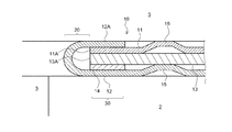
例えば、図3に示すように、シリンダブロック2とシリンダヘッド5との間に上記実施形態のガスケット10を上下反転させて介装してもよい。この場合も、上記実施形態と同様の作用効果を奏することができる。
For example, as shown in FIG. 3, the
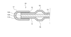
また、図4に示すように、上記実施形態のシム部材14に替えて、断面略U字状のグロメット部材17を別個に備えて構成してもよい。この場合は、各プレート11〜13に略同径の燃焼室孔(貫通孔)11A〜13Aを形成すると共に、各プレート11〜13の貫通孔11A〜13Aの周縁をグロメット部材17で覆い、さらに、下側シールプレート11に下方に突出する下側ビード16を、上側シールプレート12に上方に突出する上側ビード15をそれぞれ設ければよい。
Moreover, as shown in FIG. 4, it may replace with the
また、ガスケット10の各ビード15,16はフルビードに限定されず、例えばハーフビードであってもよい。この場合も、上記実施形態と同様の作用効果を奏することができる。
Moreover, each
また、簡易のためプレートの積層枚数は3枚で説明したが、本発明の趣旨の構造をとるものは適宜積層枚数を変更して実施することが可能である。 For simplicity, the number of stacked plates has been described as three. However, the plate having the structure of the gist of the present invention can be implemented by appropriately changing the number of stacked plates.
また、ガスケット10は、シリンダヘッドガスケットに限定されず、排気マニホールドのシリンダヘッドへの取付け面やターボチャージャの取付け面等の他の部位に用いられるガスケットにも広く適用することが可能である。
Further, the
1 エンジン
2 シリンダブロック
3 シリンダボア
4 ピストン
5 シリンダヘッド
10 ガスケット
11 下側シールプレート
12 上側シールプレート
12A 折り返し部
13 中間プレート
14 シム部材
15 上側ビード
16 下側ビード
17 グロメット部材
20 グロメット構造
30 ストッパー構造
DESCRIPTION OF
Claims (3)
前記第1貫通孔と同心の第2貫通孔を有すると共に、前記下側シールプレートの上面に積層された中間プレートと、
前記第1及び前記第2貫通孔と同心の第3貫通孔を有すると共に、前記中間プレートの上面に積層されたシム部材と、
前記シム部材の上面から前記下側シールプレートの下面に折り返されて、前記第1貫通孔の周縁、前記第2貫通孔の周縁及び、前記第3貫通孔の周縁を覆うグロメット構造を有する上側シールプレートと、
前記下側シールプレートに前記中間プレートとは反対側に突出して形成された下側ビードと、
前記上側シールプレートに前記下側ビードと同方向に突出して形成された上側ビードと、を備える
ことを特徴とするガスケット。 A lower seal plate having a first through hole;
An intermediate plate having a second through hole concentric with the first through hole and laminated on an upper surface of the lower seal plate;
A shim member having a third through hole concentric with the first and second through holes and laminated on the upper surface of the intermediate plate;
An upper seal having a grommet structure that is folded back from the upper surface of the shim member to the lower surface of the lower seal plate and covers the periphery of the first through hole, the periphery of the second through hole, and the periphery of the third through hole Plates,
A lower bead formed on the lower seal plate so as to protrude on the opposite side of the intermediate plate;
An upper bead formed on the upper seal plate so as to protrude in the same direction as the lower bead.
請求項1に記載のガスケット。 The gasket according to claim 1, wherein the lower bead is formed on the lower seal plate outside the grommet structure, and the upper bead is formed on the upper seal plate outside the shim member.
請求項1に記載のガスケット。 The upper seal plate is laminated on the upper surface of the intermediate plate without the shim member, and the grommet structure is formed separately from the upper seal plate, and from the upper surface of the upper seal plate to the lower seal plate The gasket according to claim 1, wherein the upper bead is formed on the upper seal plate so as to protrude to the opposite side of the lower bead.
Priority Applications (1)
| Application Number | Priority Date | Filing Date | Title |
|---|---|---|---|
| JP2016080867A JP2017190834A (en) | 2016-04-14 | 2016-04-14 | gasket |
Applications Claiming Priority (1)
| Application Number | Priority Date | Filing Date | Title |
|---|---|---|---|
| JP2016080867A JP2017190834A (en) | 2016-04-14 | 2016-04-14 | gasket |
Publications (1)
| Publication Number | Publication Date |
|---|---|
| JP2017190834A true JP2017190834A (en) | 2017-10-19 |
Family
ID=60085138
Family Applications (1)
| Application Number | Title | Priority Date | Filing Date |
|---|---|---|---|
| JP2016080867A Pending JP2017190834A (en) | 2016-04-14 | 2016-04-14 | gasket |
Country Status (1)
| Country | Link |
|---|---|
| JP (1) | JP2017190834A (en) |
Cited By (1)
| Publication number | Priority date | Publication date | Assignee | Title |
|---|---|---|---|---|
| KR20190118011A (en) * | 2018-04-09 | 2019-10-17 | 동아공업 주식회사 | Gasket for turo charger |
-
2016
- 2016-04-14 JP JP2016080867A patent/JP2017190834A/en active Pending
Cited By (2)
| Publication number | Priority date | Publication date | Assignee | Title |
|---|---|---|---|---|
| KR20190118011A (en) * | 2018-04-09 | 2019-10-17 | 동아공업 주식회사 | Gasket for turo charger |
| KR102102401B1 (en) * | 2018-04-09 | 2020-04-29 | 동아공업 주식회사 | Gasket for turo charger |
Similar Documents
| Publication | Publication Date | Title |
|---|---|---|
| JP2007139177A (en) | Gasket | |
| US8042815B2 (en) | Cylinder head gasket and engine | |
| JPH0581796B2 (en) | ||
| US8016296B2 (en) | Metal laminate gasket | |
| JP5992032B2 (en) | Multilayer metal gasket with beads on stopper | |
| JP2008202625A (en) | Laminated gasket | |
| JP3949690B2 (en) | Metal laminated gasket | |
| US9869271B2 (en) | Cylinder head gasket | |
| JP4056503B2 (en) | Metal gasket | |
| JP2017190834A (en) | gasket | |
| JP5729353B2 (en) | Cylinder head gasket | |
| JP4541399B2 (en) | Metal gasket | |
| JP4541400B2 (en) | Metal gasket | |
| JP5975357B2 (en) | Cylinder head gasket | |
| JP2009156061A (en) | Cylinder head gasket | |
| JP2009191870A (en) | Metal gasket | |
| JP4008002B2 (en) | Metal laminated gasket | |
| US7014194B2 (en) | Cylinder head gasket | |
| CN104246320B (en) | Plate gasket and sealing structure | |
| JP5753315B2 (en) | Metal gasket | |
| JP2010038299A (en) | Metal gasket | |
| JP2008202422A (en) | Cylinder head gasket | |
| JP6007932B2 (en) | Cylinder head gasket | |
| JP2001200755A (en) | gasket | |
| JP2002031237A (en) | Metal gasket |