JP4357806B2 - Brake warning device and brake warning switch device - Google Patents
Brake warning device and brake warning switch device Download PDFInfo
- Publication number
- JP4357806B2 JP4357806B2 JP2002206969A JP2002206969A JP4357806B2 JP 4357806 B2 JP4357806 B2 JP 4357806B2 JP 2002206969 A JP2002206969 A JP 2002206969A JP 2002206969 A JP2002206969 A JP 2002206969A JP 4357806 B2 JP4357806 B2 JP 4357806B2
- Authority
- JP
- Japan
- Prior art keywords
- brake
- brake pedal
- vehicle
- driver
- braking
- Prior art date
- Legal status (The legal status is an assumption and is not a legal conclusion. Google has not performed a legal analysis and makes no representation as to the accuracy of the status listed.)
- Expired - Lifetime
Links
Images


Landscapes
- Lighting Device Outwards From Vehicle And Optical Signal (AREA)
Description
【0001】
【産業上の利用分野】
本願の発明は、自動車の制動予告装置および制動予告スイッチ装置に関し、特に従来の制動警告灯が点灯する前に、後続車に対し、制動状態に移行したことを予告して、追突事故を未然に防止するようにした自動車の制動予告装置および該制動予告装置に使用されて好適な制動予告スイッチ装置に関する。
【0002】
【従来の技術】
従来、市販の自動車の制動警告灯は、ブレーキペダルを踏み込むことにより、車体後部に取り付けられた赤色のブレーキランプ(制動警告灯)が点灯して、後続車の注意を喚起し、追突事故を防ぐようになっている。この場合に、ブレーキランプを、後続車が見易いように、車体後部の高い所(ハイマウント)に取り付けたものもある。
【0003】
このように、従来の市販の自動車のブレーキランプは、ブレーキペダルを踏まなければ、点灯しないようになっていて、ブレーキ操作の決断からブレーキランプの点灯までの間に”遊び”が設けられている。自動車は、自然減速によりスムースに流れることが一番重要なことであり、この”遊び”は、このような自動車のスムースな流れを可能にする。また、不要な急ブレーキを解消して、運転者を衝撃から守る上で重要であるが、後続車に対しては、それだけ制動警告が遅れて、追突事故の危険性が増大することになる。
【0004】
走行中の自動車が、自然減速の状態にはあるが、運転者の足が、アクセルペダ ルからブレーキペダルに軽く移動して、制動状態に移行する状態にあることを後続車に知らせることができれば、後続車の運転者は、それだけ早く、前方車が制動状態に移行することを事前に察知することができ、追突事故の危険性を大きく低減することができる。
【0005】
このような、前方車が制動状態に移行する状態にあることを後続車に予告することができる装置を開示したものとして、特開2000−159008号公報がある。この公報においては、そのような装置が4例、紹介されている。
【0006】
第1のものは、ブレーキペダルに移動した運転者の足を距離設定型の反射型センサーが検出すると、予告灯が点灯するようになっている。しかしながら、この方法によると、検出物体の検出点における形状の如何によっては、反射する光の帰りが少ないものがあり、このような場合には、反射光を捕捉し得ず、検出物体を検出することに失敗する事態が生ずる虞がある。例えば、光を吸収する物、白い物、白や黒色のエナメルの靴や長靴等の表面がつるつるした物では、そのような事態が生ずる可能性が高い。
【0007】
また、第2のものは、ブレーキペダルの上面にタッチセンサーを設けて、運転者の足が該タッチセンサーに接触すると、予告灯が点灯するようになっている。しかしながら、従来、ブレーキペダルの素材は、ゴムや金属であり、滑り止めが付いたものとされており、その上面にタッチセンサーを設けることは、好ましいことではない。しかも、ブレーキペダルの上面には、水、土、ごみ等が付着して、反応が正確には得られない虞がある。さらに、タッチセンサーの強度の点からも、好ましいものではない。
【0008】
また、第3のものは、アクセルペダルの後側床面にセンサーを設け、運転者がアクセルペダルからブレーキペダルに踏み替える際、運転者の踵が該センサーから離れることを該センサーが感知すると、予告灯が点灯するようになっている。しかしながら、このものにおいては、運転者がアクセルペダルから足を離したからといって、ブレーキペダルを踏むとは限らず、そのような場合にも制動灯が点灯することは、後続車の運転手に紛らわしく、かえって、後続車の安全運転を損なうことにもなりかねない。
【0009】
さらに、第4のものは、アクセルペダルと連結したスロットルレバーに近接させてセンサーを設け、運転者の足がアクセルペダルから離れると、該センサーが作動して、予告灯が点灯するようになっている。しかしながら、このものにあっても、前記した、アクセルペダルの後側床面にセンサーを設けた場合と同様の欠点がある。
【0010】
これらの4例に示された制動予告装置は、いずれも、それぞれが備える反射型センサー、タッチセンサー、床面設置センサー、スロットルレバー位置検出センサーの出力がリレーに入力され、リレーが作動して、予告灯に直列に配されたスイッチを開閉動するようになっているものであり、これら各センサーとリレーとスイッチとにより、制動予告スイッチ装置が構成されている。
【0011】
【発明が解決しようとする課題】
本願の発明は、従来の自動車の制動予告装置および制動予告スイッチ装置が有する前記のような問題点を解決して、走行中の自動車が、自然減速の状態にはあるが、運転者の足が、アクセルペダルからブレーキペダルに軽く移動して、制動状態に移行する状態にあることを後続車に知らせるのに、確実に知らせることができ、自動車の関連部品の構造を大きく変更することなく、安価に実施することができて、これらにより、追突事故の危険性を大きく低減することができる自動車の制動予告装置および制動予告スイッチ装置を提供することを課題とする。
【0012】
【課題を解決するための手段および効果】
前記のような課題は、本願の各請求項に記載された発明が備える次のような手段により解決される。
本願の請求項1に記載された発明は、自動車のブレーキペダルを踏む運転者の足によりそのビームが遮られるようにして、透過型センサーを設け、車体後部の後続車の視認可能な位置に、制動予告灯を設け、前記透過型センサーと前記制動予告灯とを電気的に接続し、運転者の足が、前記ブレーキペダルを踏もうとして、前記透過型センサーのビームを遮ると、前記透過型センサーが作動して、前記制動予告灯を点灯するようにした自動車の制動予告装置において、前記自動車のブレーキペダルに、前記透過型センサーのビームが通過し得る孔もしくは切欠き凹部を設けて、前記自動車のブレーキペダルを踏む運転者の足によりそのビームが遮られるようにしたことを特徴とする自動車の制動予告装置である。
【0013】
請求項1に記載された発明は、前記のように構成されているので、次のような効果を奏することができる。
運転者の足が、ブレーキペダルを踏もうとして、透過型センサーのビームを遮ると、該透過型センサーが作動して、制動予告灯を点灯するようになっているので、走行中の自動車が、自然減速の状態にはあるが、運転者の足が、アクセルペダルからブレーキペダルに軽く移動して、制動状態に移行する状態にあることを後続車に確実に知らせて、注意を喚起することができ、後続車の運転者は、それだけ早く、前方車が制動状態に移行することを事前に察知して、追突事故の危険性を大きく低減することができる。特に高速運転において、その効果は顕著である。さらに、透過型センサーの部品(投光部、受光部)が土、水等で汚されたり、運転者の靴に接触して破損したりする虞が解消されて、装置の信頼性が向上する。
【0014】
また、この自動車の制動予告装置は、自動車のブレーキペダルを踏む運転者の足によりそのビームが遮られるようにして、透過型センサーを設け、車体後部の後続車の視認可能な位置に制動予告灯を設け、該透過型センサーと該制動予告灯とを電気的に接続するという簡単な構成により得られるので、安価であり、既存の自動車にも容易に応用でき、広く実施可能なものである。
【0015】
加えて、その自動車のブレーキペダルに、透過型センサーのビームが通過し得る孔もしくは切欠き凹部を設けて、自動車のブレーキペダルを踏む運転者の足によりそのビームが遮られるようにしているので、自動車のブレーキペダルを踏む運転者の足により透過型センサーのビームが遮られるようにするのに、自動車のブレーキペダルに、透過型センサーのビームが通過し得る孔もしくは切欠き凹部を設けるだけで済み、ブレーキペダルに加えられる構造の変更も軽微で、構造が非常に簡単であり、透過型センサーの設置を安価に実施することができる。
【0016】
また、その請求項2に記載された発明は、請求項1に記載の自動車の制動予告装置において、その制動予告灯は、黄色灯とされたことを特徴としている。
【0017】
これにより、走行中の自動車が、自然減速の状態にはあるが、運転者の足が、アクセルペダルからブレーキペダルに軽く移動して、制動状態に移行する状態にある(つまり、ブレーキペダルを踏み込む前の状態にある)場合には、黄色の制動予告灯のみが点灯して、制動状態への移行状態にあることを後続車に示し、急ブレーキを踏んだ場合には、点灯時刻にわずかの差はあるが、黄色の制動予告灯と従来の赤色の制動警告灯とが略同時に点灯して、急ブレーキを掛けたことを後続車に知らせることができ、後続車の注意を一層喚起して、追突事故の危険性をさらに大きく低減することができる。
【0018】
さらに、その請求項3に記載された発明は、自動車のブレーキペダルを踏む運転者の足によりそのビームが遮られるようにして、透過型センサーを設け、前記自動車のブレーキペダルに、前記透過型センサーのビームが通過し得る孔もしくは切欠き凹部を設けて、前記自動車のブレーキペダルを踏む運転者の足によりそのビームが遮られるのを前記透過型センサーが感知して制動予告のための電気回路を閉にするように構成されていることを特徴とする自動車の制動予告スイッチ装置である。
【0019】
請求項3に記載された発明は、前記のように構成されているので、次のような効果を奏することができる。
運転者の足が、ブレーキペダルを踏もうとして、透過型センサーのビームを遮ると、該透過型センサーがこれを感知して制動予告のための電気回路(制動予告電気回路)を閉にするように作動するので、走行中の自動車が、自然減速の状態にはあるが、運転者の足が、アクセルペダルからブレーキペダルに軽く移動して、制動状態に移行する状態にあることを予告することが可能になり、例えば、この制動予告電気回路に制動予告灯が接続される場合には、後続車の運転者は、それだけ早く、前方車が制動状態に移行することを事前に目視により察知して、追突事故の危険性を大きく低減することができる。特に高速運転において、その効果が顕著である。また、透過型センサーの部品(投光部、受光部)が土、水等で汚されたり、運転者の靴に接触して破損したりする虞が解消されて、スイッチの信頼性が向上する。
【0020】
また、自動車のブレーキペダルを踏む運転者の足により透過型センサーのビームが遮られるようにするのに、自動車のブレーキペダルに、透過型センサーのビームが通過し得る孔もしくは切欠き凹部を設けるだけで済むので、ブレーキペダルに加えられる構造の変更も軽微で、構造が非常に簡単であり、透過型センサーの設置を安価に実施することができる。
【0021】
【発明の実施の形態】
次に、図1ないし図3に図示される本願の請求項1〜3に記載された発明の一実施形態について説明する。
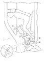
図1は、本実施形態における自動車の制動予告装置および制動予告スイッチ装置が適用された自動車の運転席部の概略側面図、図2は、同自動車の背面図、図3は、同制動予告装置の電気回路図である。
【0022】
図1に図示されるように、本実施形態における自動車の制動予告装置および制動予告スイッチ装置が適用された自動車1のブレーキ操作部2は、運転者の足が直接に触れるブレーキペダル2a と、該ブレーキペダル2a を支え、運転者の足の動作を後続のブレーキ用流体圧発生機構に伝達する支杆(アーム)2b とから成っている。
【0023】
ブレーキペダル2a には、運転席から見てやや手前側で、左右方向略中央部を貫通するようにして、透過型センサー5(図3参照)のビームBが通過し得る孔3が設けられている。この孔3は、自動車1の走行中の振動を考慮しても、ビームBが間違いなくこの孔3を通過し得るように、10mm〜30mmの直径の孔として形成されている。
【0024】
透過型センサー5は、投光部5a と受光部5b とを備えた赤色光センサーであり、その投光部5a は、運転席前方のインスツルメントパネル6の下壁に取り付けられ、その受光部5b は、フロア7の前方部の運転者の足により覆われない位置に取り付けられている。そして、ブレーキ操作部2が操作されないスムースな走行状態においては、投光部5a から発せられた赤色光ビームBは、ブレーキペダル2a に形成された孔3を通過して受光部5b に到達するようになっている。なお、図1において、4はアクセル操作部、8は操舵ハンドルである。
【0025】
また、自動車1の車体後部の後続車の視認可能な位置には、車体下方左右にそれぞれ設けられた方向指示灯9、制動警告灯10、後退灯11に加えて、車体上方中央部に、制動予告灯12が設けられている。これら方向指示灯9、制動警告灯10、後退灯11は、従来と同じものであり、従来通りに作動して、方向指示灯9は黄色の灯光を、制動警告灯10と後退灯11とは赤色の灯光を、それぞれ発するようになっている。
【0026】
制動予告灯12は、後述するように、走行中の自動車1が、自然減速の状態にはあるが、運転者の足が、アクセル操作部4のペダルからブレーキペダル2a に軽く移動して、制動状態に移行する状態にある(つまり、ブレーキペダル2a を踏み込む前の状態にある)場合に、黄色に点灯して、自動車1が制動状態への移行状態にあることを後続車に知らせるものである。
【0027】
透過型センサー5と制動予告灯12とは、図3に図示されるように、電気的に接続されている。
図3において、バッテリー14に並列に制動予告灯12、制動警告灯10、その他図示されない方向指示灯9、後退灯11等が接続されており、これらに対して直列にリレー13が接続されている。また、透過型センサー5も、バッテリー14に並列に接続され、これより電源を得るようにされている。
【0028】
そこで、今、走行中の自動車1の運転者の足が、ブレーキペダル2a を踏もうとして、透過型センサー5のビームBを遮ると、透過型センサー5がこれを感知して作動して、その出力がリレー13に入力される。そうすると、リレー13は、制動予告灯12のスイッチをオンして、これを点灯させる。孔3が形成されたブレーキペダル2a 、透過型センサー5、リレー13、制動予告灯12のスイッチ等は、制動予告灯12が接続された制動予告のための電気回路(制動予告電気回路)を開閉するスイッチ装置(制動予告スイッチ装置)を構成している。
【0029】
運転者の足の動作がさらに進んで、ブレーキペダル2a を実際に踏み込むと、リレー13は、制動警告灯10のスイッチをオンして、これを点灯させる。したがって、急ブレーキを踏んだ場合には、点灯時刻にわずかの差はあるが、黄色の制動予告灯12と赤色の制動警告灯10とが略同時に点灯して、急ブレーキを掛けたことを後続車に知らせることができ、後続車の注意を一層喚起して、追突事故の危険性を大きく低減することができる。
【0030】
ブレーキペダル2a に形成された孔3は、図4に図示されるように、ブレーキペダル2a の周縁の1個所に形成された半円状の切欠き凹部15によって代えられてもよい。この場合にあっても、ブレーキ操作部2が操作されないスムースな走行状態において、透過型センサー5の投光部5a から発せられたビームBが、この切欠き凹部15を通過して受光部5b に到達するようにされれば、透過型センサー5は、前記と同様に作動することができ、ブレーキペダル2a に施す加工も比較的簡単になる。なお、この切欠き凹部15は、ブレーキペダル2a の運転席に近い側の周縁部に設けられるのがよい。
【0031】
本実施形態の自動車の制動予告装置および制動予告スイッチ装置は、前記のように構成されているので、次のような効果を奏することができる。
運転者の足が、ブレーキペダル2a を踏もうとして、透過型センサー5のビームBを遮ると、透過型センサー5がこれを感知して作動して、制動予告灯12を点灯するようになっているので、走行中の自動車1が、自然減速の状態にはあるが、運転者の足が、アクセルペダルからブレーキペダル2a に軽く移動して、制動状態に移行する状態にあることを後続車に確実に知らせて、注意を喚起することができ、後続車の運転者は、それだけ早く、前方車が制動状態に移行することを事前に察知して、追突事故の危険性を大きく低減することができる。特に高速運転において、その効果が顕著に発揮される。さらに、透過型センサー5の部品(投光部5a 、受光部5b )が土、水等で汚されたり、運転者の靴に接触して破損したりする虞が解消されて、装置の信頼性が向上する。
【0032】
また、このような自動車の制動予告装置は、自動車1のブレーキペダル2a に透過型センサー5のビームBが通過し得る孔3もしくは切欠き凹部15を設け、車体後部の後続車の視認可能な位置に制動予告灯12を設け、透過型センサー5と制動予告灯12とを電気的に接続するという簡単な構成により得られるので、ブレーキペダル2a に加えられる構造の変更も軽微で済み、構造が非常に簡単であり、安価に実施することができ、既存の自動車にも容易に応用でき、広く実施可能なものである。
【0033】
さらに、制動予告灯12は、黄色灯とされているので、走行中の自動車1が、自然減速の状態にはあるが、運転者の足が、アクセルペダルからブレーキペダル2a に軽く移動して、制動状態に移行する状態にある場合には、黄色の制動予告灯12のみが点灯して、制動状態への移行状態にあることを後続車に示し、急ブレーキを踏んだ場合には、点灯時刻にわずかの差はあるが、黄色の制動予告灯12と従来の赤色の制動警告灯10とが略同時に点灯して、急ブレーキを掛けたことを後続車に知らせることができ、後続車の注意を一層喚起して、追突事故の危険性をさらに大きく低減することができる。
【0034】
なお、本願の発明の応用として、以下のような変形例(変形例1、2)も考えられる。
図5は、本変形例1における自動車の制動予告装置および制動予告スイッチ装置が適用された自動車のブレーキの概略部分側面図である。
【0035】
本変形例1における自動車の制動予告装置および制動予告スイッチ装置は、先の本願の発明の実施形態における自動車の制動予告装置および制動予告スイッチ装置と比較すると、その自動車1のブレーキ操作部2が、次のように異なっている。すなわち、実施形態1においては、ブレーキペダル2a に孔3が設けられたが、本実施形態2においては、これが設けられておらず、代わりに、図5に図示されるように、支杆伸長部2c が設けられている。
【0036】
この支杆伸長部2c は、ブレーキペダル2a の支杆2b を、運転席から見てブレーキペダル2a よりも手前側に、上方に屈曲させつつ、わずかに伸長させて形成されるたものである。そして、その先端部には、透過型センサーの受光部5b が取り付けられている。なお、この支杆伸長部2c は、支杆2b の手前側端部に溶着等により取り付けられてもよい。
【0037】
ブレーキペダル2a は、支柱2d により、支杆2b から離反して上方に変位させられており、これにより、足の踏み込み方向に見て、ブレーキペダル2a の位置が支杆伸長部2c の先端部より上位にあるようにされている。このようにすることにより、ブレーキペダル2a の踏込み時、足が受光部5b に接触するのを防止することができる。
【0038】
以上のような構成において、インスツルメントパネル6の下壁に取り付けられた透過型センサー5の投光部5a から発せられたビームBは、ブレーキペダル2a の直近を通過して支杆伸長部2c の先端部に設けられた受光部5b に到達することができ、走行中の自動車1の運転者の足が、ブレーキペダル2a を踏もうとして、このビームBを遮ると、透過型センサー5が作動して、実施形態1におけると同様に、制動予告灯12を点灯させることができる。
【0039】
なお、以上のような構成において、支柱2d を設ける代わりに、支杆伸長部2c をU字状の屈曲杆とし、屈曲部が下方に突出するように配置構成して、前記と同様の、ブレーキペダル2a と支杆伸長部2c の先端部との位置関係を得るようにしてもよい。また、支杆2b の形状が、元々、支柱2d を含む程度に湾曲して形成されている場合には、特に支柱2d を設ける必要はない。この場合には、支杆伸長部2c は、支杆2b の手前側端部近傍から分岐され、ブレーキペダル2a よりも手前側にまで伸長させられて形成されることになる。支杆伸長部2c の先端部に取り付けられる受光部5b は、投光部5a に代えられてもよい。
【0040】
本変形例1における自動車の制動予告装置および制動予告スイッチ装置は、以上の点において先の実施形態における自動車の制動予告装置および制動予告スイッチ装置と異なっているが、その他の点において異なるところはないので、詳細な説明を省略する。
【0041】
本変形例1は、前記のように構成されているので、先の実施形態と同様の制動予告効果を奏することができる。
また、自動車1のブレーキペダル2a を踏む運転者の足により透過型センサー1のビームBが遮られるようにするのに、自動車1のブレーキペダル2a の支杆2b を、運転席から見てブレーキペダル2a よりも手前側にわずかに伸長させて、その先端部に、透過型センサー5の投光部5a もしくは受光部5b を取り付けるだけで済むので、ブレーキ操作部2に加えられる構造の変更も軽微で済み、構造が簡単で、透過型センサー5の設置を安価に実施することができる。
【0042】
次に、図6に図示される変形例2について説明する。
図6は、本変形例2における自動車の制動予告装置および制動予告スイッチ装置が適用された自動車のブレーキの概略部分側面図である。
【0043】
本変形例2における自動車の制動予告装置および制動予告スイッチ装置は、変形例1における自動車の制動予告装置および制動予告スイッチ装置と比較すると、その自動車1のブレーキ操作部2が、支杆伸長部2c に代えて、図6に図示されるように、屈曲支片2e を備えている点において異なっている。
【0044】
この屈曲支片2e は、自動車1のブレーキペダル2a の下面から伸長させられ、その先端部が、運転席から見てブレーキペダル2a よりもわずかに手前側で、ブレーキペダル2a を踏む運転者の足が接触しない高さ位置にあるようにして、ブレーキペダル2a と溶着等により一体に設けられたものであり、その先端部には、透過型センサーの投光部5a もしくは受光部5b が取り付けられている。
【0045】
本変形例2における自動車の制動予告装置および制動予告スイッチ装置は、以上の点において変形例1における自動車の制動予告装置および制動予告スイッチ装置と異なっているが、その他の点において異なるところはないので、詳細な説明を省略する。
【0046】
本変形例2は、前記のように構成されているので、先の実施形態及び変形例1と同様の制動予告効果を奏することができる。
また、自動車1のブレーキペダル2a を踏む運転者の足により透過型センサー5のビームBが遮られるようにするのに、自動車1のブレーキペダル2a の下面から屈曲支片2eを伸長させ、その先端部が、運転席から見てブレーキペダル2a よりもわずかに手前側で、ブレーキペダル2a を踏む運転者の足が接触しない位置にあるようにし、その先端部に、透過型センサーの投光部5a もしくは受光部5b を取り付けるだけで済むので、ブレーキペダル2a に加えられる構造の変更も軽微で済み、構造が簡単で、透過型センサー5の設置を安価に実施することができる。
【0047】
本願の発明は、以上に説明したような実施形態に限定されず、その発明の要旨を逸脱しない範囲において、種々の実施の形態が可能である。
【図面の簡単な説明】
【図1】 本願の請求項1〜3に記載された発明の一実施形態における自動車の制動予告装置および制動予告スイッチ装置が適用された自動車の運転席部の概略側面図である。
【図2】 同自動車の背面図である。
【図3】 同制動予告装置の電気回路図である。
【図4】 同自動車のブレーキペダルの変形例を示す図である。
【図5】 本願の発明の応用としての変形例1における自動車の制動予告装置および制動予告スイッチ装置が適用された自動車のブレーキの概略部分側面図である。
【図6】 本願の発明の応用としての変形例2における自動車の制動予告装置および制動予告スイッチ装置が適用された自動車のブレーキの概略部分側面図である。
【符号の説明】
1…自動車、2…ブレーキ操作部、2a …ブレーキペダル、2b …支杆、2c …支杆伸長部、2d …支柱、2e …屈曲支片、3…孔、4…アクセル操作部、5…透過型センサー、5a …投光部、5b …受光部、6…インスツルメントパネル、7…フロア、8…操舵ハンドル、9…方向指示灯、10…制動警告灯、11…後退灯、12…制動予告灯、13…リレー、14…バッテリー、15…切欠き凹部。[0001]
[Industrial application fields]
The invention of the present application relates to a brake warning device and a brake warning switch device for an automobile, and in particular, before a conventional brake warning light is turned on, a rear-end vehicle is informed in advance of a transition to a braking state, and a rear-end collision is caused in advance. The present invention relates to a braking notice device for an automobile which is prevented and a braking notice switch device suitable for use in the braking notice device.
[0002]
[Prior art]
Conventionally, the brake warning light of a commercially available car lights up the red brake lamp (brake warning light) attached to the rear of the vehicle body by depressing the brake pedal, alerting the following vehicle, and preventing rear-end collisions. It is like that. In this case, there is a brake lamp mounted at a high position (high mount) at the rear of the vehicle body so that the following vehicle can be easily seen.
[0003]
In this way, the brake lamps of conventional commercial vehicles are not turned on unless the brake pedal is depressed, and "play" is provided between the decision of the brake operation and the turning on of the brake lamp. . It is most important that the car flows smoothly by natural deceleration, and this “play” enables such a smooth flow of the car. In addition, it is important to eliminate unnecessary sudden braking and protect the driver from impact, but for the following vehicle, the braking warning is delayed and the risk of a rear-end accident increases.
[0004]
If the car in motion is in a state of natural deceleration, but the driver's foot can be moved lightly from the accelerator pedal to the brake pedal to inform the following vehicle that it is in a state of shifting to the braking state, The driver of the succeeding vehicle can detect in advance that the preceding vehicle will shift to the braking state, and the risk of a rear-end collision can be greatly reduced.
[0005]
Japanese Patent Application Laid-Open No. 2000-159008 discloses an apparatus that can notify a subsequent vehicle that a preceding vehicle is in a state of shifting to a braking state. In this publication, four examples of such devices are introduced.
[0006]
In the first case, when the distance setting type reflective sensor detects the driver's foot that has moved to the brake pedal, a warning light is turned on. However, according to this method, depending on the shape of the detection point of the detection object, there is a thing with little return of the reflected light. In such a case, the reflected light cannot be captured and the detection object is detected. There is a risk of failure. For example, such a situation is likely to occur in an object that absorbs light, a white object, or an object having a smooth surface such as white or black enamel shoes or boots.
[0007]
In the second type, a touch sensor is provided on the upper surface of the brake pedal, and when a driver's foot touches the touch sensor, a warning light is turned on. Conventionally, however, the brake pedal is made of rubber or metal and is provided with a non-slip material, and it is not preferable to provide a touch sensor on the upper surface of the brake pedal. In addition, water, dirt, dust, etc. may adhere to the upper surface of the brake pedal, and the reaction may not be obtained accurately. Furthermore, it is not preferable from the viewpoint of the strength of the touch sensor.
[0008]
Further, the third one is provided with a sensor on the rear floor of the accelerator pedal, and when the driver switches from the accelerator pedal to the brake pedal, when the sensor detects that the driver's heel is separated from the sensor, A warning light comes on. However, in this case, just because the driver removes his / her foot from the accelerator pedal, the brake pedal is not necessarily depressed. However, it can also impair safe driving of the following cars.
[0009]
Furthermore, the fourth one is provided with a sensor close to the throttle lever connected to the accelerator pedal, and when the driver's foot is separated from the accelerator pedal, the sensor is activated and the warning light is turned on. Yes. However, even in this case, there are the same disadvantages as in the case where the sensor is provided on the rear floor of the accelerator pedal.
[0010]
In each of the four examples of the brake notice device, the output of the reflective sensor, the touch sensor, the floor installation sensor, and the throttle lever position detection sensor included in each is input to the relay, the relay is activated, A switch arranged in series with the warning light is opened and closed, and a brake warning switch device is constituted by these sensors, relays and switches.
[0011]
[Problems to be solved by the invention]
The invention of the present application solves the above-mentioned problems of the conventional automobile brake warning device and brake warning switch device, and the running vehicle is in a state of natural deceleration, but the driver's feet By moving lightly from the accelerator pedal to the brake pedal, it is possible to reliably notify the following vehicle that it is in the state of shifting to the braking state, and it is inexpensive without significantly changing the structure of the related parts of the car Therefore, it is an object of the present invention to provide a braking notice device and a braking notice switch device for an automobile that can greatly reduce the risk of a rear-end collision accident.
[0012]
[Means for solving the problems and effects]
The above problems are solved by the following means included in the invention described in each claim of the present application.
The invention described in
[0013]
Since the invention described in
When the driver's foot tries to step on the brake pedal and blocks the beam of the transmission sensor, the transmission sensor is activated and the brake warning light is turned on. Although it is in the state of natural deceleration, the driver's foot can move lightly from the accelerator pedal to the brake pedal, and can surely notify the following vehicle that it is in the state of shifting to the braking state, and call attention. The driver of the following vehicle can detect in advance that the preceding vehicle will shift to the braking state in advance, and can greatly reduce the risk of a rear-end collision accident. The effect is particularly remarkable in high-speed operation. Furthermore, the possibility of the parts of the transmission sensor (light projecting part, light receiving part) being soiled with soil, water, etc. or being damaged by contact with the driver's shoes is eliminated, thereby improving the reliability of the device. .
[0014]
In addition, this vehicle brake warning device is provided with a transmissive sensor so that the beam is blocked by the foot of a driver who steps on the brake pedal of the vehicle, and a brake warning light is provided at a visible position of the following vehicle at the rear of the vehicle body. And the transmission type sensor and the brake warning light are electrically connected to each other, so that it is inexpensive, can be easily applied to existing automobiles, and can be widely implemented.
[0015]
In addition, the brake pedal of the car is provided with a hole or notch recess through which the beam of the transmission sensor can pass, so that the beam is blocked by the foot of the driver who steps on the brake pedal of the car. To ensure that the beam of the transmission sensor is blocked by the foot of the driver who steps on the brake pedal of the vehicle, it is only necessary to provide a hole or notch recess in the vehicle brake pedal through which the beam of the transmission sensor can pass. The change of the structure applied to the brake pedal is also slight, the structure is very simple, and the transmission type sensor can be installed at low cost.
[0016]
The invention described in
[0017]
As a result, the running vehicle is in a state of natural deceleration, but the driver's feet are lightly moved from the accelerator pedal to the brake pedal and are in a state of shifting to the braking state (that is, the brake pedal is depressed). In the previous state), only the yellow brake warning light is lit, indicating to the following vehicle that it is in the state of transition to the braking state. Although there is a difference, the yellow braking warning light and the conventional red braking warning light are lit almost simultaneously to notify the following vehicle that the sudden braking has been applied, further raising the attention of the following vehicle In addition, the risk of rear-end collision can be further reduced.
[0018]
Further , the invention described in claim 3 is provided with a transmission sensor so that the beam is blocked by a foot of a driver who steps on a brake pedal of an automobile, and the transmission sensor is provided on the brake pedal of the automobile. A hole or notch recess through which the beam of the vehicle can pass is provided, and the transmission sensor senses that the beam is blocked by the foot of the driver who steps on the brake pedal of the automobile, and an electric circuit for warning of braking is provided. A braking notice switch device for an automobile characterized by being configured to be closed.
[0019]
Since the invention described in claim 3 is configured as described above, the following effects can be obtained.
When the driver's feet try to step on the brake pedal and block the beam of the transmission type sensor, the transmission type sensor detects this and closes the electric circuit for braking warning (braking warning electric circuit). The vehicle that is running is in a state of natural deceleration, but the driver's feet are lightly moved from the accelerator pedal to the brake pedal and are in a state of shifting to the braking state. For example, when a braking warning light is connected to this braking warning electric circuit, the driver of the following vehicle visually recognizes in advance that the preceding vehicle will shift to the braking state as soon as possible. Therefore, the risk of rear-end collision can be greatly reduced. The effect is particularly remarkable in high-speed operation. Also, the reliability of the switch is improved by eliminating the possibility that parts of the transmission sensor (light projecting part, light receiving part) will be soiled with soil, water, etc., or damaged by contact with the driver's shoes. .
[0020]
In addition, in order to block the beam of the transmission sensor by the foot of the driver who steps on the brake pedal of the automobile, only a hole or a notch recess through which the beam of the transmission sensor can pass is provided in the brake pedal of the automobile. Therefore, the change of the structure applied to the brake pedal is slight, the structure is very simple, and the transmission type sensor can be installed at low cost.
[0021]
DETAILED DESCRIPTION OF THE INVENTION
Next, a description will be given of one exemplary form state of the invention described in
Figure 1 is a schematic side view of a driver's seat of the vehicle brake warning device and the braking warning switch device of a vehicle definitive in this embodiment shaped condition is applied, FIG. 2 is a rear view of the motor vehicle, FIG. 3, the braking It is an electric circuit diagram of a notice device.
[0022]
As illustrated in Figure 1, the
[0023]
The
[0024]
The transmissive sensor 5 is a red light sensor including a
[0025]
In addition to the
[0026]
As will be described later, the
[0027]
The transmissive sensor 5 and the
In FIG. 3, a
[0028]
Therefore, when the driver's foot of the
[0029]
When the driver's foot moves further and the
[0030]
As shown in FIG. 4, the hole 3 formed in the
[0031]
Braking warning device and the braking warning switch device of an automobile of the present embodiment forms condition, which is configured as described above, can be obtained the following effects.
When the driver's foot tries to step on the
[0032]
In addition, such a vehicle brake warning device is provided with a hole 3 or a
[0033]
Furthermore, since the
[0034]
Note that the following modifications (
FIG. 5 is a schematic partial side view of a brake of an automobile to which the automobile brake notice device and the brake notice switch device according to the first modification are applied.
[0035]
Braking warning device and the braking warning switch device of an automobile in the
[0036]
The
[0037]
The
[0038]
In the configuration as described above, the beam B emitted from the
[0039]
In the configuration as described above, instead of providing the
[0040]
The vehicle brake warning device and the brake warning switch device in the first modification are different from the vehicle brake warning device and the brake warning switch device in the previous embodiment in the above points, but there is no difference in other points. Therefore, detailed description is omitted.
[0041]
Since the first modification example is configured as described above, the same brake notice effect as that of the previous embodiment can be obtained.
Further, in order to block the beam B of the
[0042]
Next,
FIG. 6 is a schematic partial side view of a vehicle brake to which the vehicle brake notification device and the brake notification switch device according to the second modification are applied.
[0043]
Braking warning device and the braking warning switch device of an automobile in this modified example 2, when compared with the vehicle brake warning device and the braking warning switch device in
[0044]
The
[0045]
The vehicle brake notice device and the brake notice switch device according to the second modification are different from the vehicle brake notice device and the brake notice switch device according to the first modification in the above points, but there is no difference in other points. Detailed description will be omitted.
[0046]
Since the present modified example 2 is configured as described above, it is possible to achieve the same brake notice effect as the previous embodiment and modified example 1 .
Further, in order to block the beam B of the transmission type sensor 5 by the foot of the driver who steps on the
[0047]
The invention of the present application is not limited to the embodiment described above, and various embodiments are possible without departing from the gist of the invention.
[Brief description of the drawings]
1 is a schematic side view of a driver's seat of the vehicle brake warning device and the braking warning switch device is applied for automobile definitive to an exemplary shaped condition of the invention described in
FIG. 2 is a rear view of the vehicle.
FIG. 3 is an electric circuit diagram of the braking notice device.
FIG. 4 is a view showing a modification of the brake pedal of the vehicle.
FIG. 5 is a schematic partial side view of an automobile brake to which a braking notice device and a braking notice switch device for an automobile according to
FIG. 6 is a schematic partial side view of a vehicle brake to which a vehicle brake warning device and a brake warning switch device according to a second modification as an application of the invention of the present application are applied.
[Explanation of symbols]
DESCRIPTION OF
Claims (3)
車体後部の後続車の視認可能な位置に、制動予告灯を設け、
前記透過型センサーと前記制動予告灯とを電気的に接続し、
運転者の足が、前記ブレーキペダルを踏もうとして、前記透過型センサーのビームを遮ると、前記透過型センサーが作動して、前記制動予告灯を点灯するようにした自動車の制動予告装置において、
前記自動車のブレーキペダルに、前記透過型センサーのビームが通過し得る孔もしくは切欠き凹部を設けて、前記自動車のブレーキペダルを踏む運転者の足によりそのビームが遮られるようにしたことを特徴とする自動車の制動予告装置。A transmission sensor is provided so that the beam is blocked by the foot of the driver who steps on the brake pedal of the car,
A braking warning light is provided at a position where the vehicle behind the vehicle can be seen,
Electrically connecting the transmission type sensor and the brake warning light;
In a braking notice device for an automobile in which a driver's foot tries to step on the brake pedal and interrupts the beam of the transmission sensor, the transmission sensor is activated and the braking warning light is turned on .
The vehicle brake pedal is provided with a hole or a notch recess through which the beam of the transmission type sensor can pass, and the beam is blocked by a driver's foot stepping on the vehicle brake pedal. Car brake warning device.
前記自動車のブレーキペダルに、前記透過型センサーのビームが通過し得る孔もしくは切欠き凹部を設けて、
前記自動車のブレーキペダルを踏む運転者の足によりそのビームが遮られるのを前記透過型センサーが感知して制動予告のための電気回路を閉にするように構成されていることを特徴とする自動車の制動予告スイッチ装置。A transmission sensor is provided so that the beam is blocked by the foot of the driver who steps on the brake pedal of the car,
The brake pedal of the automobile is provided with a hole or notch recess through which the beam of the transmission type sensor can pass,
An automobile characterized in that the transmission type sensor senses that the beam is blocked by a driver's foot stepping on the brake pedal of the automobile and the electric circuit for warning of braking is closed. Braking warning switch device.
Priority Applications (1)
| Application Number | Priority Date | Filing Date | Title |
|---|---|---|---|
| JP2002206969A JP4357806B2 (en) | 2002-07-16 | 2002-07-16 | Brake warning device and brake warning switch device |
Applications Claiming Priority (1)
| Application Number | Priority Date | Filing Date | Title |
|---|---|---|---|
| JP2002206969A JP4357806B2 (en) | 2002-07-16 | 2002-07-16 | Brake warning device and brake warning switch device |
Publications (3)
| Publication Number | Publication Date |
|---|---|
| JP2004050864A JP2004050864A (en) | 2004-02-19 |
| JP2004050864A5 JP2004050864A5 (en) | 2004-12-16 |
| JP4357806B2 true JP4357806B2 (en) | 2009-11-04 |
Family
ID=31931549
Family Applications (1)
| Application Number | Title | Priority Date | Filing Date |
|---|---|---|---|
| JP2002206969A Expired - Lifetime JP4357806B2 (en) | 2002-07-16 | 2002-07-16 | Brake warning device and brake warning switch device |
Country Status (1)
| Country | Link |
|---|---|
| JP (1) | JP4357806B2 (en) |
Families Citing this family (1)
| Publication number | Priority date | Publication date | Assignee | Title |
|---|---|---|---|---|
| CN106696925B (en) * | 2015-08-28 | 2020-08-28 | 北京宝沃汽车有限公司 | Brake pedal assembly, brake control system and vehicle |
-
2002
- 2002-07-16 JP JP2002206969A patent/JP4357806B2/en not_active Expired - Lifetime
Also Published As
| Publication number | Publication date |
|---|---|
| JP2004050864A (en) | 2004-02-19 |
Similar Documents
| Publication | Publication Date | Title |
|---|---|---|
| JP5972332B2 (en) | Approach notification device for saddle riding type vehicles | |
| EP2534009B1 (en) | Vehicle notification sound emitting apparatus | |
| US6388580B1 (en) | Automobile unsafe following distance warning system | |
| US8768566B2 (en) | Vehicle having active blind spot lighting and method | |
| JP6400215B2 (en) | Vehicle control apparatus and vehicle control method | |
| EP2534008B1 (en) | Vehicle notification sound emitting apparatus | |
| JP2010073134A (en) | Vehicle surrounding recognition support system | |
| JP2009501105A (en) | Flashing switch for automobile with adaptive speed controller | |
| US20120296520A1 (en) | Vehicle notification sound emitting apparatus | |
| JP2009040236A (en) | Vehicular notification device | |
| WO2005025936A2 (en) | Steering wheel for vehicle, vehicle, and direction indication device | |
| US7400237B2 (en) | Signaling system for use in a vehicle to provide a signal indicative of a change in a vehicle speed | |
| US20100265057A1 (en) | Attentive device applied to vehicles | |
| JP4357806B2 (en) | Brake warning device and brake warning switch device | |
| JP5935348B2 (en) | Vehicle control device | |
| US6356190B1 (en) | Brake early warning system and method of use | |
| JP2004050864A5 (en) | ||
| JP2005193799A (en) | Braking notice switching device of automobile | |
| JP5949217B2 (en) | Electric vehicle | |
| JP6056990B2 (en) | Electric vehicle | |
| JPH11301348A (en) | Road surface lighting device of vehicle | |
| JP2008150011A (en) | Alarm device for preventing improper operation of accelerator of automobile | |
| JPH11334464A (en) | Display device for automobile | |
| KR100789674B1 (en) | Automotive covering safety distance alarm system | |
| JP2003335172A (en) | Safety system |
Legal Events
| Date | Code | Title | Description |
|---|---|---|---|
| A521 | Request for written amendment filed |
Free format text: JAPANESE INTERMEDIATE CODE: A523 Effective date: 20040106 |
|
| A621 | Written request for application examination |
Free format text: JAPANESE INTERMEDIATE CODE: A621 Effective date: 20050621 |
|
| A977 | Report on retrieval |
Free format text: JAPANESE INTERMEDIATE CODE: A971007 Effective date: 20080305 |
|
| A131 | Notification of reasons for refusal |
Free format text: JAPANESE INTERMEDIATE CODE: A131 Effective date: 20080401 |
|
| A521 | Request for written amendment filed |
Free format text: JAPANESE INTERMEDIATE CODE: A523 Effective date: 20080530 |
|
| A02 | Decision of refusal |
Free format text: JAPANESE INTERMEDIATE CODE: A02 Effective date: 20080715 |
|
| A01 | Written decision to grant a patent or to grant a registration (utility model) |
Free format text: JAPANESE INTERMEDIATE CODE: A01 |
|
| A61 | First payment of annual fees (during grant procedure) |
Free format text: JAPANESE INTERMEDIATE CODE: A61 Effective date: 20090805 |
|
| FPAY | Renewal fee payment (event date is renewal date of database) |
Free format text: PAYMENT UNTIL: 20120814 Year of fee payment: 3 |
|
| R150 | Certificate of patent or registration of utility model |
Ref document number: 4357806 Country of ref document: JP Free format text: JAPANESE INTERMEDIATE CODE: R150 Free format text: JAPANESE INTERMEDIATE CODE: R150 |
|
| FPAY | Renewal fee payment (event date is renewal date of database) |
Free format text: PAYMENT UNTIL: 20120814 Year of fee payment: 3 |
|
| FPAY | Renewal fee payment (event date is renewal date of database) |
Free format text: PAYMENT UNTIL: 20150814 Year of fee payment: 6 |
|
| R250 | Receipt of annual fees |
Free format text: JAPANESE INTERMEDIATE CODE: R250 |
|
| R250 | Receipt of annual fees |
Free format text: JAPANESE INTERMEDIATE CODE: R250 |
|
| R250 | Receipt of annual fees |
Free format text: JAPANESE INTERMEDIATE CODE: R250 |
|
| R250 | Receipt of annual fees |
Free format text: JAPANESE INTERMEDIATE CODE: R250 |
|
| R250 | Receipt of annual fees |
Free format text: JAPANESE INTERMEDIATE CODE: R250 |
|
| R250 | Receipt of annual fees |
Free format text: JAPANESE INTERMEDIATE CODE: R250 |
|
| EXPY | Cancellation because of completion of term |