JP4357430B2 - Loader working machine - Google Patents

Loader working machine Download PDF

Info

Publication number
JP4357430B2
JP4357430B2 JP2005022001A JP2005022001A JP4357430B2 JP 4357430 B2 JP4357430 B2 JP 4357430B2 JP 2005022001 A JP2005022001 A JP 2005022001A JP 2005022001 A JP2005022001 A JP 2005022001A JP 4357430 B2 JP4357430 B2 JP 4357430B2
Authority
JP
Japan
Prior art keywords
main frame
frame
boss portion
side frame
boss
Prior art date
Legal status (The legal status is an assumption and is not a legal conclusion. Google has not performed a legal analysis and makes no representation as to the accuracy of the status listed.)
Active
Application number
JP2005022001A
Other languages
Japanese (ja)
Other versions
JP2006207293A5 (en
JP2006207293A (en
Inventor
寛樹 福留
正 中尾
修一 竹下
Current Assignee (The listed assignees may be inaccurate. Google has not performed a legal analysis and makes no representation or warranty as to the accuracy of the list.)
Kubota Corp
Original Assignee
Kubota Corp
Priority date (The priority date is an assumption and is not a legal conclusion. Google has not performed a legal analysis and makes no representation as to the accuracy of the date listed.)
Filing date
Publication date
Application filed by Kubota Corp filed Critical Kubota Corp
Priority to JP2005022001A priority Critical patent/JP4357430B2/en
Publication of JP2006207293A publication Critical patent/JP2006207293A/en
Publication of JP2006207293A5 publication Critical patent/JP2006207293A5/ja
Application granted granted Critical
Publication of JP4357430B2 publication Critical patent/JP4357430B2/en
Active legal-status Critical Current
Anticipated expiration legal-status Critical

Links

Images

Description

本発明は、トラクタ等の走行車体の前部に装着されるフロントローダ等のローダ作業機に関するものである。   The present invention relates to a loader working machine such as a front loader attached to a front portion of a traveling vehicle body such as a tractor.

従来、ローダ作業機には、走行車体に取り付けられるメインフレームと、ブームを支持するサイドフレームとを備え、メインフレームとサイドフレームとにそれぞれボス部が設けられ、メインフレームに対してサイドフレームが揺動自在に係合され、メインフレームのボス部とサイドフレームのボス部とが一致するサイドフレームの揺動位置でサイドフレームのメインフレームに対する揺動を規制するように、メインフレーム又はサイドフレームの一方に、他方のボス部に接当するストッパーが設けられ、メインフレームとサイドフレームとに前記一致したボス部を介してマウントピンを挿通することにより、メインフレームにサイドフレームを着脱自在に固定するようにしたものがあり、この種の従来のローダ作業機では、ボス部とストッパーとを互いに別体に構成して、ボス部とストッパーとをメインフレーム又はサイドフレームの一方に、それぞれ別々に溶接等により固着していた(例えば特許文献1、特許文献2)。
特開2001−132006号 特開2000−309940公報
Conventionally, a loader work machine includes a main frame attached to a traveling vehicle body and a side frame that supports a boom, and a boss portion is provided on each of the main frame and the side frame, and the side frame swings with respect to the main frame. One of the main frame or the side frame is movably engaged so as to regulate the swing of the side frame relative to the main frame at the swing position of the side frame where the boss portion of the main frame coincides with the boss portion of the side frame. In addition, a stopper that comes into contact with the other boss portion is provided, and the side frame is detachably fixed to the main frame by inserting a mount pin through the matched boss portion into the main frame and the side frame. In this type of conventional loader work machine, the boss part and the stop are Constitute the over to separate members, and a boss portion and the stopper on one of the main frame or side frames, has been fixed by each separately welding (for example, Patent Document 1, Patent Document 2).
JP 2001-132006 A JP 2000-309940 A

従来のローダ作業機では、メインフレーム又はサイドフレームの一方に、ストッパーを溶接等により固着する際に、メインフレーム又はサイドフレームの他方のボス部に対応するように位置決めすることが難しく、このため、ストッパーのメインフレーム又はサイドフレームの一方への固着が面倒であるという問題があった。
そこで、本発明は、前記問題点に鑑み、ストッパーをメインフレーム又はサイドフレームに対して簡単に位置決めしてストッパーを容易かつ確実に固着することができるようにしたものである。
In the conventional loader work machine, when fixing the stopper to one of the main frame or the side frame by welding or the like, it is difficult to position the stopper so as to correspond to the other boss part of the main frame or the side frame. There has been a problem that the fixing of the stopper to either the main frame or the side frame is troublesome.
Therefore, in view of the above problems, the present invention is configured so that the stopper can be easily and surely fixed by easily positioning the stopper with respect to the main frame or the side frame.

この技術的課題を解決するための本発明の技術的手段は、走行車体に取り付けられるメインフレームと、ブームを支持するサイドフレームとを備え、メインフレームとサイドフレームとにそれぞれボス部が設けられ、メインフレームに対してサイドフレームが揺動自在に係合され、メインフレームのボス部とサイドフレームのボス部とが一致するサイドフレームの揺動位置でサイドフレームのメインフレームに対する揺動を規制するように、メインフレーム又はサイドフレームの一方に、他方のボス部に接当するストッパーが設けられ、メインフレームとサイドフレームとに前記一致したボス部を介してマウントピンを挿通することにより、メインフレームにサイドフレームを着脱自在に固定するようにしたローダ作業機において、
前記メインフレーム又はサイドフレームの一方のボス部とストッパーとが、一体に形成されて、メインフレーム又はサイドフレームの一方に固着され
前記メインフレーム又はサイドフレームの一方に、該一方のボス部を内嵌固着するための取付孔が設けられ、ストッパーを、メインフレーム又はサイドフレームの他方のボス部に対応させるべくボス部廻りの回転方向に位置決めするように、前記ボス部と取付孔との間に位置決め機構が設けられている点にある。
The technical means of the present invention for solving this technical problem includes a main frame attached to the traveling vehicle body and a side frame that supports the boom, and a boss portion is provided on each of the main frame and the side frame, The side frame is slidably engaged with the main frame, and the swing of the side frame with respect to the main frame is regulated at the swing position of the side frame where the boss portion of the main frame and the boss portion of the side frame coincide. In addition, one of the main frame and the side frame is provided with a stopper that comes into contact with the other boss part, and the main frame and the side frame are inserted into the main frame by inserting the mount pin through the matched boss part. In the loader work machine which fixed the side frame detachably,
The one boss part and the stopper of the main frame or side frame are integrally formed and fixed to one of the main frame or side frame ,
One of the main frame or the side frame is provided with an attachment hole for internally fitting and fixing the one boss, and the stopper is rotated around the boss so as to correspond to the other boss of the main frame or the side frame. A positioning mechanism is provided between the boss portion and the mounting hole so as to be positioned in the direction .

また、本発明の他の技術的手段は、前記メインフレーム又はサイドフレームの一方に、該一方のボス部を内嵌固着するための取付孔が設けられ、ストッパーを、メインフレーム又はサイドフレームの他方のボス部に対応させるべく位置決めするように、前記ボス部と取付孔との間に位置決め機構が設けられている点にある。
また、本発明の他の技術的手段は、前記位置決め機構は、互いに嵌合する嵌合凸部と嵌合凹部により構成され、嵌合凸部は、ボス部側又は取付孔側の一方に設けられ、嵌合凹部は、ボス部側又は取付孔側の他方に設けられている点にある。
Further, according to another technical means of the present invention, an attachment hole for internally fitting and fixing the one boss portion is provided on one of the main frame or the side frame, and the stopper is provided on the other side of the main frame or the side frame. A positioning mechanism is provided between the boss portion and the mounting hole so as to be positioned so as to correspond to the boss portion.
According to another technical means of the present invention, the positioning mechanism includes a fitting convex portion and a fitting concave portion that are fitted to each other, and the fitting convex portion is provided on one of the boss portion side or the mounting hole side. The fitting recess is provided on the other side of the boss portion side or the attachment hole side.

また、本発明の他の技術的手段は、前記メインフレームのボス部とサイドフレームのボス部とは、互いに同一径の円筒状に形成され、前記ストッパーに、メインフレーム又はサイドフレームの他方のボス部を嵌合する嵌合溝が設けられている点にある。
また、本発明の他の技術的手段は、前記メインフレームのボス部及びサイドフレームのボス部は、マウントピンを挿通するための挿通孔を有する円筒状に形成され、メインフレームとサイドフレームとに、それぞれボス部を挿通するための取付孔が設けられ、各ボス部は取付孔を介してメインフレーム又はサイドフレームにそれぞれ挿通されて、溶接等により固着されている点にある。
According to another technical means of the present invention, the boss portion of the main frame and the boss portion of the side frame are formed in a cylindrical shape having the same diameter, and the other boss of the main frame or the side frame is provided on the stopper. This is in that a fitting groove for fitting the portion is provided.
According to another technical means of the present invention, the boss portion of the main frame and the boss portion of the side frame are formed in a cylindrical shape having an insertion hole for inserting the mount pin. Each has a mounting hole for inserting a boss portion, and each boss portion is inserted through the mounting hole into the main frame or the side frame and fixed by welding or the like.

また、本発明の他の技術的手段は、前記サイドフレームは、左右一対の側壁を備え、この一対の側壁に左右に対応して取付孔がそれぞれ設けられ、側壁の左右方向内方側にストッパーを位置させて、取付孔にボス部が挿通されて、ボス部の挿入端部が側壁の左右方向外方側に突出され、一対の側壁の左右方向内面に、ストッパーが接当又は接近した状態とされ、
メインフレームの上部側は、サイドフレームの左右一対の側壁間に挿入され、メインフレームのボス部は、メインフレームの上部側に、左右一対の側壁に向けて突出するように固着されている点にある。
Further, according to another technical means of the present invention, the side frame includes a pair of left and right side walls, mounting holes are respectively provided on the pair of side walls corresponding to the left and right sides, and a stopper is provided on the inner side in the left and right direction of the side walls. The boss part is inserted through the mounting hole, the insertion end of the boss part protrudes outward in the left-right direction of the side wall, and the stopper is in contact with or close to the inner surface in the left-right direction of the pair of side walls. And
The upper side of the main frame is inserted between the pair of left and right side walls of the side frame, and the boss portion of the main frame is fixed to the upper side of the main frame so as to protrude toward the pair of left and right side walls. is there.

本発明によれば、ストッパーと一体に形成したボス部によって、ストッパーが他方のボス部に接当してサイドフレームの揺動を規制する位置が、サイドフレームのボス部とメインフレームのボス部とが一致する位置になるように、ストッパーの固着位置を、簡単に設定することができ、ストッパーをメインフレーム又はサイドフレームに位置決めして、ストッパーを容易かつ確実にメインフレーム又はサイドフレームに取り付けることができる。   According to the present invention, the position where the stopper comes into contact with the other boss portion by the boss portion formed integrally with the stopper and restricts the swing of the side frame is the boss portion of the side frame and the boss portion of the main frame. The position where the stopper is fixed can be easily set so that the positions match each other, and the stopper can be positioned on the main frame or side frame so that the stopper can be easily and reliably attached to the main frame or side frame. it can.

以下、本発明の実施の形態を図面を参照して説明する。
図1において、1は、作業車(荷役車両)として例示する、トラクタ(走行車体)2の前部にフロントローダ3を装着してなるトラクタ装着式のローダ作業機である。
トラクタ2は左右一対の前後輪4,5を有する2軸4輪形トラクタで、前部にエンジン、ラジエータ等を覆うボンネット6が設けられており、このボンネット6は上面等が湾曲状に形成されている。
フロントローダ3は、トラクタ2に設けられた取付フレーム7に着脱自在に取り付けられるサイドフレーム13と、このサイドフレーム13に基部側が枢支連結されたブーム8と、この左右ブーム8の先端側に取り付けられた作業具としてのバケット9とを有する。
Hereinafter, embodiments of the present invention will be described with reference to the drawings.
In FIG. 1, reference numeral 1 denotes a tractor-mounted loader working machine, which is exemplified as a work vehicle (loading vehicle) and has a front loader 3 mounted on the front portion of a tractor (traveling vehicle body) 2.
The tractor 2 is a two-shaft four-wheel tractor having a pair of left and right front and rear wheels 4, 5. A bonnet 6 that covers an engine, a radiator, and the like is provided at the front, and the bonnet 6 is formed with a curved upper surface. Yes.
The front loader 3 is attached to a side frame 13 detachably attached to a mounting frame 7 provided on the tractor 2, a boom 8 whose base side is pivotally connected to the side frame 13, and a front load side of the left and right booms 8. And a bucket 9 as a working tool.

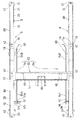
取付フレーム7は、図10及び図11に示すように、トラクタ2の前部の下部(ボンネット6の後端側の下方側)に、該トラクタ2から左右方向外方突出状に設けられた支持台11と、この支持台11に、該支持台11から上方突出状に設けられたメインフレーム12と、この支持台11の左右方向内端側に固定されていてトラクタ2に取付固定された取付板10とを左右一対備える。従って、メインフレーム12は走行車体2に取り付けられ、サイドフレーム13はブーム8を支持している。
図2に示すように、ブーム8及びサイドフレーム13は左右一対設けられていて、ボンネット6の左右両側に配置されており、左右のブーム8はその前部側において、円筒状のブーム連結体14によって相互に連結されており、サイドフレーム13は左右方向で同じ側にあるメインフレーム12に取り付けられる。
As shown in FIGS. 10 and 11, the mounting frame 7 is a support provided on the lower part of the front portion of the tractor 2 (below the rear end side of the bonnet 6) so as to protrude in the left-right direction from the tractor 2. A base 11, a main frame 12 provided on the support base 11 so as to project upward from the support base 11, and an attachment fixed to the tractor 2 by being fixed to the inner side in the left-right direction of the support base 11 A pair of left and right plates 10 are provided. Therefore, the main frame 12 is attached to the traveling vehicle body 2, and the side frame 13 supports the boom 8.
As shown in FIG. 2, the boom 8 and the side frame 13 are provided in a pair on the left and right sides of the bonnet 6, and the left and right booms 8 have a cylindrical boom connector 14 on the front side thereof. The side frames 13 are attached to the main frame 12 on the same side in the left-right direction.

左右各ブーム8は、その基端側(後端側)が左右方向で同じ側にあるサイドフレーム13の上部に枢軸36によって左右方向の軸心回りに回動自在に枢支連結されていて上下揺動自在とされている。
また、左右各ブーム8の長手方向中途部と、左右各サイドフレーム13の上下方向中途部とにわたって複動式油圧シリンダからなるブームシリンダ15が介装され、この左右ブームシリンダ15の伸縮によって左右のブーム8が上下に揺動可能とされている。
また、バケット9の背面下部には、ブラケット38が左右一対設けられ、左右方向で同じ側にあるブーム8の先端側(前端側)が枢軸37を介して枢支連結され、バケット9の背面の左右方向中央部と前記ブーム連結体14の左右方向中央部との間には、複動式油圧シリンダからなる一本のバケットシリンダ16が介装され、このバケットシリンダ16の伸縮によってバケット9が揺動可能(スクイ・ダンプ動作可能)とされている。
Each of the left and right booms 8 is pivotally connected to the upper part of the side frame 13 whose base end side (rear end side) is on the same side in the left-right direction by a pivot 36 so as to be pivotable about a horizontal axis. It can be swung freely.
In addition, a boom cylinder 15 composed of a double-acting hydraulic cylinder is interposed between the middle part in the longitudinal direction of each left and right boom 8 and the middle part in the vertical direction of each left and right side frame 13. The boom 8 can swing up and down.
In addition, a pair of left and right brackets 38 are provided at the lower rear portion of the bucket 9, and the front end side (front end side) of the boom 8 on the same side in the left and right direction is pivotally connected via a pivot 37. A single bucket cylinder 16 composed of a double-acting hydraulic cylinder is interposed between the central portion in the left-right direction and the central portion in the left-right direction of the boom coupling body 14, and the bucket 9 is shaken by the expansion and contraction of the bucket cylinder 16. It can be operated (squeeze dump operation is possible).

前記左右各ブーム8は、図1〜図3に示すように、長手方向中央部で屈曲されて上側に凸となる山形状に形成されていると共に、前後の端部から長手方向中央部に行くに従って上下幅が漸次幅広となるように形成されている。
また、このブーム8は、長手方向中央部から前側の前ブーム構成体8Aと、長手方向中央部から後側の後ブーム構成体8Bと、これら前後のブーム構成体8A,8Bをブーム8の長手方向中央側で連結する中央連結板17と、ブーム8の長手方向中央側の左右両側に配置されたサイドプレート18とから主構成されている。
Each of the left and right booms 8 is formed in a mountain shape that is bent at the center in the longitudinal direction and protrudes upward as shown in FIGS. 1 to 3, and goes from the front and rear ends to the center in the longitudinal direction. Accordingly, the upper and lower widths are formed so as to gradually become wider.
Further, the boom 8 includes a front boom constituent body 8A from the front in the longitudinal direction, a rear boom constituent 8B from the rear in the longitudinal center, and the front and rear boom constituents 8A and 8B. It is mainly composed of a central connecting plate 17 connected on the center side in the direction and side plates 18 arranged on both left and right sides on the center side in the longitudinal direction of the boom 8.

前後のブーム構成体8A,8Bは、本体19と底板20とから構成されていると共に、前後のブーム構成体8A,8Bは同一形状に形成されていて、部材の兼用化が図られている。
本体19は、左右一対の側板21と、該左右側板21の上側縁部同志を連結する天板22とから下側に開放状の断面コ字形に形成されていると共に、上側に凸となる湾曲状に形成されている。
この前後のブーム構成体8A,8Bの本体19は、一枚の板材を折曲することで断面コ字形に形成されており、且つコ字形に曲げ加工した後に、上側に凸となる湾曲状に曲げ加工されている。
The front and rear boom constituent bodies 8A and 8B are composed of a main body 19 and a bottom plate 20, and the front and rear boom constituent bodies 8A and 8B are formed in the same shape so that the members can be shared.
The main body 19 is formed in a U-shaped cross-section that is open downward from a pair of left and right side plates 21 and a top plate 22 that connects the upper edge portions of the left and right side plates 21, and is curved to be convex upward. It is formed in a shape.
The main body 19 of the front and rear boom constituent bodies 8A and 8B is formed in a U-shaped cross-section by bending a single plate material, and is bent into a U-shape and then curved upward. It is bent.

また、この前後のブーム構成体8A,8Bの本体19の上面(天板22の上面)及び下縁(左右側板21の下側縁部21a)は一定の曲率半径の円弧面に曲げ加工されている。
これによって、ブーム8の上面は前端から後端にかけて湾曲状に形成されており、ボンネット6の湾曲形状にデザイン的にマッチした形状とされている。
また、前ブーム構成体8Aの前端側には、左右側板21に亘って貫通すると共に該側板21に溶接固定された筒体からなる前枢支部23が設けられ、この前枢支部23及びバケット9の背面に設けられたブラケット38とにわたって前記枢軸37を挿通することによりバケット9が左右軸回りに回動自在に枢支連結されている。
Further, the upper surface (the upper surface of the top plate 22) and the lower edge (the lower edge portion 21a of the left and right side plates 21) of the main body 19 of the front and rear boom constituent bodies 8A and 8B are bent into circular arc surfaces having a constant radius of curvature. Yes.
As a result, the upper surface of the boom 8 is formed in a curved shape from the front end to the rear end, and has a shape that matches the curved shape of the bonnet 6 in design.
Further, a front pivot support portion 23 is provided on the front end side of the front boom structural body 8A. The front pivot support portion 23 is formed of a cylindrical body that penetrates the left and right side plates 21 and is fixed to the side plates 21 by welding. By inserting the pivot shaft 37 through the bracket 38 provided on the back surface of the bucket 9, the bucket 9 is pivotally connected so as to be rotatable about the left and right axes.

また、後ブーム構成体8Bの後端側には、左右側板21に亘って貫通すると共に該側板21に溶接固定された筒体からなる後枢支部24が設けられ、この後枢支部24及びサイドフレーム13とにわたって前記枢軸36を挿通することによりブーム8がサイドフレーム13に左右軸回りに回動自在に枢支連結されている。
左右の前ブーム構成体8Aの左右方向内方側の側板21の後部側が前記ブーム連結体14によって連結されている。
底板20は、平板で構成されており、天板22の下側で且つ左右側板21間に配置され、前後のブーム構成体8A,8Bの、ブーム8の長手方向中央側の端部から前後枢支部23,24に至るように設けられており、本体19を曲げ加工した後に、該底板20の左右の側縁部を左右側板21の内面に溶接固定している。
Further, a rear pivot portion 24 is provided on the rear end side of the rear boom constituent body 8B. The rear pivot portion 24 is formed of a cylindrical body that penetrates the left and right side plates 21 and is welded and fixed to the side plates 21. The boom 8 is pivotally connected to the side frame 13 so as to be rotatable about the left and right axes by inserting the pivot 36 through the frame 13.
The rear side of the side plate 21 on the inner side in the left-right direction of the left and right front boom components 8A is connected by the boom connector 14.
The bottom plate 20 is configured by a flat plate, and is disposed below the top plate 22 and between the left and right side plates 21, and the front and rear boom constituent bodies 8 </ b> A and 8 </ b> B are pivoted forward and backward from the end of the boom 8 in the longitudinal direction center side. It is provided so as to reach the support portions 23, 24, and after bending the main body 19, the left and right side edge portions of the bottom plate 20 are welded and fixed to the inner surfaces of the left and right side plates 21.

また、この底板20は、前後方向一端側が前後の枢支部23,24に当接し、前後方向他端側が、ブーム8の長手方向中央部の上下幅方向中途部(側板21の、ブーム8の長手方向中央側の端縁の上下方向中途部)に位置していて、底板20は、該底板20の長手方向中途部において側板21の下側の縁部に最も近接しており、該底板20中途部からブーム8の長手方向中央部に行くに従って、底板20から側板21の下側縁部21aまでの距離が、漸次大きくなるように形成されており、これによってブーム8の長手方向中央側の、底板20の下側で且つ左右側板21間に配管収容スペース25が形成されている。   The bottom plate 20 has one end in the front-rear direction abutting against the front and rear pivots 23 and 24, and the other end in the front-rear direction is a midway portion in the vertical width direction of the center portion in the longitudinal direction of the boom 8. The bottom plate 20 is located closest to the lower edge of the side plate 21 at the midway portion in the longitudinal direction of the bottom plate 20 and is located in the middle of the bottom plate 20. The distance from the bottom plate 20 to the lower side edge portion 21a of the side plate 21 is formed so as to gradually increase from the portion to the longitudinal center portion of the boom 8, thereby A pipe housing space 25 is formed below the bottom plate 20 and between the left and right side plates 21.

図3及び図4に示すように、左右一方側のブーム8(本実施の形態では右側)の配管収容スペース25に油圧配管26,27が収容されている。
油圧配管26,27はブームシリンダ15用の2本と、バケットシリンダ16用の2本との計4本が、底板20に沿うようにして配設されている。
各油圧配管26,27の後部側は、右側メインフレーム12等に設けられたコントロールバルブに油圧ホースを介して接続される。
ブームシリンダ15用の油圧配管26の前部側はブーム連結体14の下側を該ブーム連結体14に沿って左方に配設され、左側のブームシリンダ15に油圧ホースを介して接続されていると共に、該油圧配管26は右側前部側において、分岐部材28によって分岐されていて該分岐部材28は右側のブームシリンダ15に油圧ホースを介して接続されている。
As shown in FIGS. 3 and 4, hydraulic pipes 26 and 27 are housed in a pipe housing space 25 of the boom 8 on the left and right side (right side in the present embodiment).
The hydraulic pipes 26 and 27 are arranged so that a total of four hydraulic pipes 26 and 27, two for the boom cylinder 15 and two for the bucket cylinder 16, are along the bottom plate 20.
The rear side of each hydraulic pipe 26, 27 is connected to a control valve provided on the right main frame 12 or the like via a hydraulic hose.
The front side of the hydraulic piping 26 for the boom cylinder 15 is disposed on the lower side of the boom coupling body 14 along the boom coupling body 14 and connected to the left boom cylinder 15 via a hydraulic hose. The hydraulic pipe 26 is branched by a branch member 28 on the right front side, and the branch member 28 is connected to the right boom cylinder 15 via a hydraulic hose.

また、バケットシリンダ16用の油圧配管27はブーム連結体14の下側を該ブーム連結体14に沿って左方に配設され、ブーム連結体14の左右方向中央部分で油圧ホースを介してバケットシリンダ16に接続されている。
図5にも示すように、左右のブーム8を連結するブーム連結体14の下面側の左右両側には、該ブーム連結体14の下面側に沿って配設された前記油圧配管26,27を取り付けるクランプ部材39を取り付けるための取付台40が固定されている。
前述したように、ブーム8の左右方向中央側で底板20から側板21の下側縁部21aまでの距離が大きく、しかも、左右側板21間の左右幅が狭いことから、底板20を側板21に溶接するにあたって、ブーム8の長手方向中央側において側板21間に溶接トーチが入りにくく、ブーム8の長手方向中央側において側板21に対する底板20の溶接がし難い。
The hydraulic piping 27 for the bucket cylinder 16 is disposed on the lower side of the boom connection body 14 along the boom connection body 14 to the left. Connected to the cylinder 16.
As shown also in FIG. 5, the hydraulic pipes 26, 27 arranged along the lower surface side of the boom connection body 14 are provided on both the left and right sides of the lower surface side of the boom connection body 14 that connects the left and right booms 8. A mounting base 40 for mounting the clamp member 39 to be mounted is fixed.
As described above, since the distance from the bottom plate 20 to the lower edge 21a of the side plate 21 is large at the center in the left-right direction of the boom 8, and the width between the left and right side plates 21 is narrow, the bottom plate 20 is used as the side plate 21. In welding, it is difficult for a welding torch to enter between the side plates 21 on the center side in the longitudinal direction of the boom 8, and it is difficult to weld the bottom plate 20 to the side plate 21 on the center side in the longitudinal direction of the boom 8.

そこで、前後のブーム構成体8A,8Bの本体19の、ブーム8の長手方向中央側の上部側に、切欠き部29が形成されており、ブーム8の前後の各端部側からブーム8の長手方向中途部にわたっては底板20を下側から側板21に溶接し、ブーム8の長手方向中央側では底板20を上側から側板21に溶接している。
前記切欠き部29は、天板22の、ブーム8の長手方向中央側の端部からブーム長手方向に所定範囲該天板22を切り欠くと共に該切欠部分から左右側板21の上下幅方向中途部に亘って切り欠かれている。
Therefore, a notch 29 is formed on the upper side of the main body 19 of the front and rear boom constituent bodies 8A and 8B on the center side in the longitudinal direction of the boom 8, and the boom 8 The bottom plate 20 is welded to the side plate 21 from the lower side over the middle part in the longitudinal direction, and the bottom plate 20 is welded to the side plate 21 from the upper side at the longitudinal center side of the boom 8.
The notch 29 cuts the top plate 22 in a predetermined range in the boom longitudinal direction from the end of the top side of the boom 8 in the longitudinal direction of the boom 8 and at the midway portion in the vertical width direction of the left and right side plates 21 from the notch. Notched over.

前後のブーム構成体8A,8Bは、本体19に底板20を溶接固定した後、ブーム8の長手方向中央側で付き合わされて、前後の底板20同志が相互に溶接されると共に、中央連結板17及び左右のサイドプレート18をブーム構成体8A,8Bに溶接することによって連結されている。
中央連結板17は、平板を上側に凸となる湾曲状に曲げ加工することにより形成されていて、前後のブーム構成体8A,8Bの天板22にわたって設けられている。
この中央連結板17の曲率半径は、前後のブーム構成体8A,8Bの上面の曲率半径よりも小さく形成されている。
The front and rear boom constituent bodies 8A and 8B are welded and fixed to the main body 19 at the center in the longitudinal direction of the boom 8, the front and rear bottom plates 20 are welded to each other, and the central connecting plate 17 is joined. The left and right side plates 18 are connected to the boom constituent bodies 8A and 8B by welding.
The central connecting plate 17 is formed by bending a flat plate into a curved shape that protrudes upward, and is provided over the top plates 22 of the front and rear boom constituent bodies 8A and 8B.
The radius of curvature of the central connecting plate 17 is formed to be smaller than the radius of curvature of the upper surfaces of the front and rear boom constituent bodies 8A and 8B.

したがって、長手方向中央側と前後両側とでブーム8上面の曲率半径の異なるブーム8を形成するのにあたって、曲率半径の異なる部材を連結することで形成することより、ブーム8の製作が容易に行える。
左右のサイドプレート18は、ブーム8の長手方向中央側で前後ブーム構成体8A,8Bの側板21にわたるように設けられ、左右各サイドプレート18の下部には、ブーム8から下側に突出するシリンダ枢支部30が設けられ、このシリンダ枢支部30に前記ブームシリンダ15が枢支連結されている。
Therefore, when forming the boom 8 having different curvature radii on the upper surface of the boom 8 on the center side in the longitudinal direction and the front and rear sides, the boom 8 can be easily manufactured by connecting the members having different curvature radii. .
The left and right side plates 18 are provided so as to extend over the side plates 21 of the front and rear boom constituent bodies 8A and 8B on the center side in the longitudinal direction of the boom 8, and cylinders projecting downward from the boom 8 to the lower portions of the left and right side plates 18. A pivot portion 30 is provided, and the boom cylinder 15 is pivotally connected to the cylinder pivot portion 30.

なお、左右方向内側のサイドプレート18は、外側のサイドプレート18よりも前方に延出されていると共に、ブーム連結体14を挿通させるための孔41が形成されている。
前ブーム構成体8Aの天板22の前端側及び後端側と、後ブーム構成体8Bの天板22の前端側及び後端側には、それぞれ前後のブーム構成体8A,8Bの本体19を曲げ加工する際の位置決め用のガイド穴42が貫通状に形成されている。
また、前枢支部23及び後枢支部24には、枢軸36,37の外周部にグリスを給脂するためのグリスニップル43が設けられ、このグリスニップル43は、図9に示すように、前ブーム構成体8Aの天板22の前端側、後ブーム構成体8Bの天板22の後端側に形成された前記ガイド穴42に対応する位置に設けられており、ガイド穴42が給脂を行う給脂口に兼用されており、このように構成することにより、前後のブーム構成体8A,8Bの天板22によってグリスニップル43が保護されている。
The side plate 18 on the inner side in the left-right direction extends forward from the outer side plate 18 and has a hole 41 through which the boom connector 14 is inserted.
On the front end side and the rear end side of the top plate 22 of the front boom structural body 8A, and the front end side and the rear end side of the top plate 22 of the rear boom structural body 8B, the main bodies 19 of the front and rear boom structural bodies 8A and 8B are respectively provided. A guide hole 42 for positioning when bending is formed in a penetrating shape.
Further, the front pivot portion 23 and the rear pivot portion 24 are provided with grease nipples 43 for supplying grease to the outer peripheral portions of the pivot shafts 36 and 37. As shown in FIG. It is provided at a position corresponding to the guide hole 42 formed on the front end side of the top plate 22 of the boom structural body 8A and the rear end side of the top plate 22 of the rear boom structural body 8B. The grease nipple 43 is protected by the top plates 22 of the front and rear boom constituent bodies 8A and 8B.

特に、前ブーム構成体8Aの前端側のバケット枢支部分に設けられるグリスニップル43を、前枢支部23の、ブーム長手方向の前端側の面に設けたものにあっては、該グリスニップル43は砂利等によって破損しやすいことから、該グリスニップル43を保護するためにカバー部材が別途設けられるが、そうするとコストアップになるが、本実施の形態の構造では、コストアップにはならない。
図10〜図12に示すように、サイドフレーム13は、左右一対の側壁13aと、この左右側壁13aを連結する連結壁13bとから構成されている。
In particular, in the case where the grease nipple 43 provided at the bucket pivot support portion on the front end side of the front boom structure 8A is provided on the front end side surface in the boom longitudinal direction of the front pivot support portion 23, the grease nipple 43 Is easily damaged by gravel, etc., and a cover member is separately provided to protect the grease nipple 43. However, this increases the cost, but the structure of the present embodiment does not increase the cost.
As shown in FIGS. 10-12, the side frame 13 is comprised from the left-right paired side wall 13a and the connection wall 13b which connects this left-right side wall 13a.

このサイドフレーム13の下端側前部には左右方向の軸心を有する係合ピン45が設けられ、この係合ピン45はサイドフレーム13の左右の側壁13aを貫通して該側壁13aに固着されている。サイドフレーム13の上下方向中途部の後部側にボス部81とストッパー82とが設けられている。ボス部81とストッパー82とは、左右一対の側壁13aにそれぞれ左右に対応して取り付けられている。
メインフレーム12は、厚板材によって形成されて支持台11の左右方向外端側に固定されており、メインフレーム12の上部側は、サイドフレーム13の左右一対の側壁13a間に挿入され、メインフレーム12の上部には左右方向の軸心を有する円筒状のボス部47が左右方向貫通状に設けられている。メインフレーム12の上下方向中途部の前部には上方に開放状の円弧状凹溝48を有する受部材49が固着されている。
An engagement pin 45 having a left and right axial center is provided at the front end on the lower end side of the side frame 13, and the engagement pin 45 passes through the left and right side walls 13a of the side frame 13 and is fixed to the side wall 13a. ing. A boss 81 and a stopper 82 are provided on the rear side of the middle portion of the side frame 13 in the vertical direction. The boss portion 81 and the stopper 82 are attached to the pair of left and right side walls 13a so as to correspond to the left and right, respectively.
The main frame 12 is formed of a thick plate material and is fixed to the left and right outer end sides of the support base 11, and the upper side of the main frame 12 is inserted between a pair of left and right side walls 13 a of the side frame 13. A cylindrical boss portion 47 having a horizontal axis is provided in the upper portion of 12 so as to penetrate in the horizontal direction. A receiving member 49 having an open arcuate groove 48 is fixed to the front part of the middle part of the main frame 12 in the vertical direction.

メインフレーム12の受部材49の凹溝48にサイドフレーム13の係合ピン45を上方から嵌合することにより、メインフレーム12に対してサイドフレーム13が横軸(係合ピン45)廻りに前後に揺動自在に係合され、メインフレーム12に対してサイドフレーム13を横軸廻りに前後に揺動調整することにより、メインフレーム12のボス部47とサイドフレーム13のボス部81とが一致するするようになっている。そして、メインフレーム12とサイドフレーム13とに上記の如く一致したボス部47,81を介してマウントピン46を挿通することにより、メインフレーム12にサイドフレーム13を着脱自在に固定できるように構成されている。   By fitting the engagement pin 45 of the side frame 13 into the concave groove 48 of the receiving member 49 of the main frame 12 from above, the side frame 13 is moved back and forth about the horizontal axis (engagement pin 45) with respect to the main frame 12. The boss portion 47 of the main frame 12 and the boss portion 81 of the side frame 13 coincide with each other by adjusting the side frame 13 to swing back and forth about the horizontal axis with respect to the main frame 12. It is supposed to do. The mount pin 46 is inserted into the main frame 12 and the side frame 13 through the boss portions 47 and 81 that coincide with each other as described above, so that the side frame 13 can be detachably fixed to the main frame 12. ing.

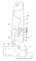
ストッパー82は、ボス部81の後方に配置されており、メインフレーム12のボス部47とサイドフレーム13のボス部81とが一致するサイドフレーム13の揺動位置で、メインフレーム12のボス部47に接当して、サイドフレーム13のメインフレーム12に対する後方揺動を規制するようになっている。
メインフレーム12のボス部47は、マウントピン46を挿通するための挿通孔84を有する円筒状に形成されている。メインフレーム12に、ボス部47を挿通するための取付孔85が設けられ、ボス部47は取付孔85を介してメインフレーム12に左右両側に突出するように挿通されて、溶接等により固着され、これにより、ボス部47は、メインフレーム12の上部側で、サイドフレーム13の左右一対の側壁13aに向けて突出されている。
The stopper 82 is disposed behind the boss portion 81, and the boss portion 47 of the main frame 12 is at the swing position of the side frame 13 where the boss portion 47 of the main frame 12 and the boss portion 81 of the side frame 13 coincide. The side frame 13 is restricted from swinging backward with respect to the main frame 12.
The boss portion 47 of the main frame 12 is formed in a cylindrical shape having an insertion hole 84 for inserting the mount pin 46. An attachment hole 85 for inserting the boss portion 47 is provided in the main frame 12, and the boss portion 47 is inserted into the main frame 12 through the attachment hole 85 so as to protrude on both the left and right sides, and is fixed by welding or the like. As a result, the boss portion 47 protrudes toward the pair of left and right side walls 13 a of the side frame 13 on the upper side of the main frame 12.

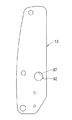
図10、図11及び図16〜図21に示すように、サイドフレーム13のボス部81はマウントピン46を挿通するための挿通孔86を有する円筒状に形成され、ストッパー82は直方体形状に形成され、これらボス部81とストッパー82とは一体に形成され、サイドフレーム13の各側壁13aにそれぞれ固着されている。
一対の側壁13aに、ボス部81を挿通するための取付孔87が左右に対応して設けられ、左右一対の側壁13の左右方向内方側にストッパー82を位置させて、取付孔87にボス部81が挿通されて、ボス部81の挿入端部が側壁13の左右方向外方側に突出され、一対の側壁13aの左右方向内面に、ストッパー82が接当(又は接近)した状態とされ、各ボス部81は取付孔87を介してサイドフレーム13の側壁13aに挿通されて、溶接等により固着されている。
As shown in FIGS. 10, 11, and 16 to 21, the boss portion 81 of the side frame 13 is formed in a cylindrical shape having an insertion hole 86 for inserting the mount pin 46, and the stopper 82 is formed in a rectangular parallelepiped shape. The boss portion 81 and the stopper 82 are integrally formed and fixed to the side walls 13a of the side frame 13, respectively.
Mounting holes 87 for inserting the boss portions 81 are provided in the pair of side walls 13a corresponding to the left and right sides. A stopper 82 is positioned on the inner side in the left and right direction of the pair of left and right side walls 13, and The portion 81 is inserted, the insertion end of the boss portion 81 protrudes outward in the left-right direction of the side wall 13, and the stopper 82 is in contact (or close) with the inner surface in the left-right direction of the pair of side walls 13 a. Each boss 81 is inserted into the side wall 13a of the side frame 13 through the mounting hole 87 and fixed by welding or the like.

ボス部81とストッパー82との境界部分の側壁13a側に、凹溝88が形成されており、これにより、ボス部81とストッパー82との境界部分に生じるアールをなくして、ストッパー82の左右方向の外端面を側壁13aの内面に接当可能にしている。
ストッパー82を、メインフレーム12のボス部47に対応させるべく位置決めするように、ボス部81と取付孔87との間に位置決め機構90が設けられている。位置決め機構90は、互いに嵌合する嵌合凸部91と嵌合凹部92により構成され、嵌合凸部91はボス部81側に形成され、嵌合凹部92は取付孔87側に形成されている。
A concave groove 88 is formed on the side wall 13a side of the boundary portion between the boss portion 81 and the stopper 82, thereby eliminating the rounding that occurs at the boundary portion between the boss portion 81 and the stopper 82, and the horizontal direction of the stopper 82. The outer end surface of the side wall can be brought into contact with the inner surface of the side wall 13a.
A positioning mechanism 90 is provided between the boss portion 81 and the mounting hole 87 so that the stopper 82 is positioned so as to correspond to the boss portion 47 of the main frame 12. The positioning mechanism 90 includes a fitting convex portion 91 and a fitting concave portion 92 that are fitted to each other, the fitting convex portion 91 is formed on the boss portion 81 side, and the fitting concave portion 92 is formed on the mounting hole 87 side. Yes.

サイドフレーム13のボス部81とサイドフレーム13のボス部47とは、互いに同一径の円筒状に形成され、ストッパー82に、メインフレーム12のボス部47を嵌合する嵌合溝93が設けられ、嵌合溝93の内面は、ボス部81の外周面と面一(同一軸心面)となる円弧面に形成されている。
サイドフレーム13の左右方向外側の側壁13a外面のマウントピン46の下方側にはプレート50が設けられ、マウントピン46の左右方向外端側にはマウントピン46よりも径小の抜止めピン51が径方向に貫通され、この抜止めピン51は、図12(a)に示すように、前記プレート50に形成された挿通孔52に挿通されており、これによってマウントピン46がサイドフレーム13及び筒体47に対して抜け止めされ、抜止めピン51を前記プレート50の挿通孔52から上方に抜脱することにより、マウントピン46がサイドフレーム13及び筒体47から抜脱できるように構成されている。
The boss portion 81 of the side frame 13 and the boss portion 47 of the side frame 13 are formed in a cylindrical shape having the same diameter, and the stopper 82 is provided with a fitting groove 93 for fitting the boss portion 47 of the main frame 12. The inner surface of the fitting groove 93 is formed as an arc surface that is flush with the outer peripheral surface of the boss portion 81 (same axis surface).
A plate 50 is provided below the mount pin 46 on the outer surface of the side wall 13a on the outer side in the left-right direction of the side frame 13, and a retaining pin 51 having a smaller diameter than the mount pin 46 is provided on the outer end side in the left-right direction of the mount pin 46. As shown in FIG. 12A, the retaining pin 51 is inserted in the radial direction, and is inserted into an insertion hole 52 formed in the plate 50, whereby the mount pin 46 is inserted into the side frame 13 and the cylinder. The mounting pin 46 is configured to be removed from the side frame 13 and the cylindrical body 47 by being prevented from being detached from the body 47 and by removing the retaining pin 51 upward from the insertion hole 52 of the plate 50. Yes.

前記プレート50に形成された挿通孔52は、マウントピン46を挿通可能な大きさの孔に形成されており、マウントピン46をサイドフレーム13及び筒体47から抜脱したときに、図12(b)に示すように、該マウントピン46をプレート50の挿通孔52に挿通することにより、マウントピン46を保持(収納)できるように構成されている。
前記フロントローダ3には、該フロントローダ3をトラクタ2から取り外したときに、図8に示すように、バケット9を接地させた状態でブーム8を支えるスタンド53を備えている。
The insertion hole 52 formed in the plate 50 is formed to have a size that allows the mount pin 46 to be inserted, and when the mount pin 46 is removed from the side frame 13 and the cylindrical body 47, FIG. As shown in b), the mount pin 46 can be held (stored) by inserting the mount pin 46 into the insertion hole 52 of the plate 50.
The front loader 3 includes a stand 53 that supports the boom 8 in a state where the bucket 9 is grounded as shown in FIG. 8 when the front loader 3 is detached from the tractor 2.

このスタンド53は、図1、図2、図5〜図8に示すように、左右のブーム8に対応して設けられた左右一対のスタンド部材54と、左右のスタンド部材54を連結する連結部材55とから主構成されており、左右のスタンド部材54の前端側が、左右各前ブーム構成体8Aの前部側に設けられた支軸56,57に左右方向の軸心廻りに回動自在に枢支されていて、該支軸56,57回りにスタンド53を回動することにより、図8に示すように、ブーム8から下方側に突出して接地し該ブーム8を支える使用位置と、図1、図5に示すように、左右スタンド部材54がブーム8に沿う非使用位置とに位置変更自在とされている。   As shown in FIGS. 1, 2, and 5 to 8, the stand 53 includes a pair of left and right stand members 54 provided corresponding to the left and right booms 8 and a connecting member that connects the left and right stand members 54. 55, and the front end sides of the left and right stand members 54 are rotatable about the left and right axial centers on the support shafts 56 and 57 provided on the front side of each of the left and right front boom members 8A. As shown in FIG. 8, by pivoting and rotating the stand 53 around the support shafts 56 and 57, as shown in FIG. As shown in FIG. 1 and FIG. 5, the left and right stand members 54 can be freely changed to a non-use position along the boom 8.

左右の各スタンド部材54は、連結部材55よりも前側の前構成部材54Aと、連結部材55よりも後側の後構成部材54Bとに2分割されており、これら前構成部材54Aと後構成部材54Bとは、それぞれ厚さ方向が左右方向となる一枚の帯板材によって形成されており、前構成部材54Aの後端側が連結部材55の前面側に溶接等によって固定され、後構成部材54Bの前端側が連結部材55の後面側に溶接等によって固定されている。
左右スタンド部材54の前構成部材54Aの前端側には、それぞれ支持孔58,59が厚さ方向(左右方向)貫通状に形成され、左右スタンド部材54の後構成部材54Bの後端側には左右方向内方側に折り曲げられて形成された接地部60が設けられている。
Each of the left and right stand members 54 is divided into a front constituent member 54A on the front side of the connecting member 55 and a rear constituent member 54B on the rear side of the connecting member 55. The front constituent member 54A and the rear constituent member 54B is formed of a single strip material whose thickness direction is the left-right direction, and the rear end side of the front component member 54A is fixed to the front side of the connecting member 55 by welding or the like. The front end side is fixed to the rear surface side of the connecting member 55 by welding or the like.
Support holes 58 and 59 are formed in the thickness direction (left and right direction) through the front end side of the front component member 54A of the left and right stand member 54, respectively, and on the rear end side of the rear component member 54B of the left and right stand member 54 A grounding portion 60 formed by being bent inward in the left-right direction is provided.

左側(左右一方側)のスタンド部材54の前構成部材54Aの支持孔58は円形孔に形成され、右側(左右他方側)のスタンド部材54の前構成部材54Aの支持孔59は四角形の角孔に形成されている。
左右のスタンド部材54を支持する左右の支軸56,57は、左右各前ブーム構成体8Aの前部の左右方向内方側の面に、左右方向の軸心を有し且つ同心状に配置されると共に左右方向内方側に突出状として設けられている。
左側の支軸56は円柱状のピンによって構成されている。
The support hole 58 of the front component member 54A of the left (right and left side) stand member 54 is formed in a circular hole, and the support hole 59 of the front component member 54A of the right (right and left side) stand member 54 is a square hole. Is formed.
The left and right support shafts 56 and 57 that support the left and right stand members 54 have a left-right axial center and are concentrically arranged on the inner surface in the left-right direction of the front portion of the left and right front boom structural body 8A. In addition, it is provided as a protruding shape on the inner side in the left-right direction.
The left support shaft 56 is constituted by a cylindrical pin.

右側の支軸57は、四角形の角柱の軸心方向中央側部分を略円柱状に削ってなるピンによって構成されており、軸心方向中央側の円柱状部分が右側スタンド部材54の回動を許容する回動許容部57aとされており、左右方向内端側の角柱部分が右側スタンド部材54の回動を規制する回動規制部57bとされている。
左側のスタンド部材54の支持孔58が左側の支軸56に嵌合し、且つ右側のスタンド部材54の支持孔59が右側の支軸57の回動許容部57aに嵌合した状態で、スタンド53が左右の支軸56,57を中心として回動自在となっていて、該スタンド53が前部側の枢支部分を支点として上下に揺動自在(上げ下げ自在)とされている。
The right support shaft 57 is configured by a pin formed by cutting a central portion of a quadrangular prism in the axial direction in a substantially cylindrical shape, and the cylindrical portion on the central side in the axial direction rotates the right stand member 54. A rotation permission portion 57 a that is allowed is formed, and a prism portion on the inner end side in the left-right direction is a rotation restriction portion 57 b that restricts the rotation of the right stand member 54.
With the support hole 58 of the left stand member 54 fitted into the left support shaft 56 and the support hole 59 of the right stand member 54 fitted into the rotation allowing portion 57a of the right support shaft 57, the stand 53 is rotatable about the left and right support shafts 56, 57, and the stand 53 is swingable up and down (can be raised and lowered) with the pivot portion on the front side as a fulcrum.

このスタンド53は左右のスタンド部材54が連結部材55によって連結されてなるので、スタンド53を使用位置と非使用位置とに位置変更させる操作は、トラクタ2の左右方向一側(右側又は左側)からだけの上げ下げ操作によって可能とされている。
また、左右のスタンド部材54は、ブーム8の左右方向内方側で回動自在とされていて、非使用時において、左右のスタンド部材54は、ブーム8の左右方向内方側に、該ブーム8と左右方向に関してオーバーラップするように位置する。
これにより、スタンド53の非使用時(収納時)において、外側方から見てスタンド部材54はブーム8によって隠されることとなり、スタンド53の非使用時における外観の向上が図られている。
Since the stand 53 has left and right stand members 54 connected by a connecting member 55, the operation of changing the position of the stand 53 between the use position and the non-use position is performed from one side (right side or left side) of the tractor 2 in the left-right direction. It is possible only by raising and lowering operation.
The left and right stand members 54 are rotatable on the inner side in the left and right direction of the boom 8. When not in use, the left and right stand members 54 are located on the inner side in the left and right direction of the boom 8. It is located so as to overlap with 8 in the left-right direction.
Thus, when the stand 53 is not used (stored), the stand member 54 is hidden by the boom 8 when viewed from the outside, and the appearance is improved when the stand 53 is not used.

また、左側のスタンド部材54の前構成部材54Aの前部には、ピン挿通孔61が支持孔58の後方側に形成されており、左側のブーム8の左右方向内方側の面には、左側の支軸56を中心とし、左側の支軸56とピン挿通孔61との軸心間距離を半径とする円弧上に位置する係止ピン62が左右方向内方側に突出状として固定されており、これらピン挿通孔61と係止ピン62とは、図6(d)に示すように、スタンド53が使用位置にある時に左右方向において軸心が略一致し、係止ピン62に対してピン挿通孔61が嵌合可能となる。   Further, a pin insertion hole 61 is formed on the rear side of the support hole 58 in the front portion of the front component member 54A of the left stand member 54, and the left inner side surface of the left boom 8 is A locking pin 62 positioned on an arc whose center is the left support shaft 56 and whose radius is the distance between the shaft centers of the left support shaft 56 and the pin insertion hole 61 is fixed in a projecting manner inward in the left-right direction. As shown in FIG. 6D, the pin insertion hole 61 and the locking pin 62 are substantially aligned with each other in the left-right direction when the stand 53 is in the use position. Thus, the pin insertion hole 61 can be fitted.

また、スタンド53が使用位置にあるときに、図6(b)に示すように、右側のスタンド部材54の支持孔59は右側の支軸57の回動規制部57aに嵌合可能となり、使用位置でスタンド部材54が左右移動可能となる(なお、右側の支持孔59が回動許容部57aに嵌合している状態からのスタンド53の右方への移動は、左側の支軸56に挿通されるベータピン等の抜止め部材によって規制されるように構成されている)。
したがって、スタンド53が使用位置に位置するときにおいて、右側の支持孔59が回動許容部57aに嵌合している状態から、該スタンド53を左方移動させることにより、左側のスタンド部材54のピン挿通孔61が係止ピン62に嵌合し、且つ右側のスタンド部材54の支持孔59が右側の支軸57の回動規制部57bに嵌合することにより、スタンド53の支軸56,57回りの回動が規制され、該スタンド53が使用位置に保持(ロック)される。
Further, when the stand 53 is in the use position, as shown in FIG. 6B, the support hole 59 of the right stand member 54 can be fitted into the rotation restricting portion 57a of the right support shaft 57. The stand member 54 can be moved left and right at the position (Note that the movement of the stand 53 to the right from the state in which the right support hole 59 is fitted to the rotation allowing portion 57a is applied to the left support shaft 56. It is configured to be regulated by a retaining member such as a beta pin to be inserted).
Therefore, when the stand 53 is located at the use position, the stand 53 is moved to the left from the state in which the right support hole 59 is fitted to the rotation allowing portion 57a. When the pin insertion hole 61 is fitted to the locking pin 62 and the support hole 59 of the right stand member 54 is fitted to the rotation restricting portion 57b of the right support shaft 57, the support shaft 56 of the stand 53, The rotation around 57 is restricted, and the stand 53 is held (locked) in the use position.

この状態で、係止ピン62にベータピン等の抜止め部材を挿通することにより、スタンド53の右方への移動が規制される。
なお、右側の支軸57の左右方向外端側の角柱部57cは、スタンド53の着脱用とされており、この角柱部57cに右側のスタンド部材54の支持孔59を嵌合させるようにスタンド53を右方に移動させることにより、左側のスタンド部材54の支持孔58が左側の支軸56から外れるように構成されている。
前記連結部材55は、前壁部63と、後壁部64と、これら前後壁部63,64の下端側同志を連結する底壁部65とを有して、左右及び上側が開放状となる溝形に形成されている。
In this state, by inserting a retaining member such as a beta pin into the locking pin 62, the movement of the stand 53 to the right is restricted.
Note that the prism portion 57c on the right and left outer ends of the right support shaft 57 is used for attaching and detaching the stand 53, and the support hole 59 of the right stand member 54 is fitted into the prism portion 57c. By moving 53 to the right, the support hole 58 of the left stand member 54 is configured to be disengaged from the left support shaft 56.
The connecting member 55 includes a front wall portion 63, a rear wall portion 64, and a bottom wall portion 65 that connects lower end sides of the front and rear wall portions 63 and 64, and the left and right and upper sides are open. It is formed in a groove shape.

また、連結部材55は、スタンド53を非使用位置としたときに、図5に示すように、ブーム連結体14の下側において該ブーム連結体14に沿うように位置して該ブーム連結体14に沿って設けられた油圧配管26,27、取付台40及びクランプ部材39を下側から覆うように構成され、スタンド53の非使用時において該連結部材55が油圧配管26,27等を保護するカバーとなっている。
また、連結部材55の底壁部65の左右方向略中央部にはピン挿通孔66が形成され、ブーム連結体14の下面側の左右方向略中央部には、スタンド53が非使用位置にあるときにおいて、前記ピン挿通孔66が嵌合可能な係止ピン67が下方側に突出状に固定されている。
Further, as shown in FIG. 5, the connecting member 55 is positioned along the boom connecting body 14 below the boom connecting body 14 when the stand 53 is set to the non-use position. The hydraulic pipes 26 and 27, the mounting base 40, and the clamp member 39 provided along the upper and lower sides are covered from below, and the connecting member 55 protects the hydraulic pipes 26 and 27 and the like when the stand 53 is not used. It is a cover.
Further, a pin insertion hole 66 is formed in the substantially central portion of the bottom wall portion 65 of the connecting member 55 in the left-right direction, and the stand 53 is in a non-use position at the substantially central portion in the left-right direction on the lower surface side of the boom connector 14. In some cases, a locking pin 67 into which the pin insertion hole 66 can be fitted is fixed in a projecting manner on the lower side.

したがって、スタンド53を非使用位置にして係止ピン67の抜止め孔68にベータピン等の抜止めピンを挿通することにより、スタンド53を非使用位置に保持できるように構成されている。
この係止ピン67はフロントローダ3の左右方向略中央部にあるので、該係止ピン67に対して抜止めピンを挿脱するのはトラクタ2の左右どちらからでも可能である。
前記構成のフロントローダ3をトラクタ2から取り外すには、例えば、先ずバケット9の底部の先端側を接地させると共にスタンド53を非使用位置から下げて使用位置とした状態でマウントピン46をサイドフレーム13のボス部81及びメインフレーム12のボス部47から抜脱する。取り外したマウントピン46はプレート50の挿通孔52に挿通して保持する。
Therefore, the stand 53 can be held in the non-use position by inserting the retaining pin such as a beta pin into the retaining hole 68 of the locking pin 67 with the stand 53 in the non-use position.
Since the locking pin 67 is located at a substantially central portion in the left-right direction of the front loader 3, the retaining pin can be inserted into and removed from either the left or right of the tractor 2.
In order to remove the front loader 3 having the above-described configuration from the tractor 2, for example, the front end side of the bottom portion of the bucket 9 is first grounded and the mount pin 46 is moved to the side frame 13 with the stand 53 lowered from the non-use position to the use position. The boss portion 81 and the boss portion 47 of the main frame 12 are removed. The removed mount pin 46 is inserted and held in the insertion hole 52 of the plate 50.

次に、バケットシリンダ16を収縮させていくと、ブーム8が下降してスタンド53の接地部60が接地した後、サイドフレーム13が上昇するようにスタンド53の接地部60回りにブーム8が揺動して、メインフレーム12の受部材49の凹溝48からサイドフレーム13の係合ピン45が上方に外れ、図8に示すように、フロントローダ3が、バケット9の底部が接地した状態でブーム8がスタンド53によって支えられたスタンディング状態とされる。
その後、フロントローダ3に配設された油圧配管26,27からコントロールバルブ側に接続された油圧ホースを切り離し、トラクタ2を後退させる。
Next, when the bucket cylinder 16 is contracted, the boom 8 swings around the grounding portion 60 of the stand 53 so that the boom 8 is lowered and the grounding portion 60 of the stand 53 is grounded, and then the side frame 13 is lifted. The engaging pin 45 of the side frame 13 is disengaged upward from the concave groove 48 of the receiving member 49 of the main frame 12, and the front loader 3 is in a state where the bottom of the bucket 9 is grounded as shown in FIG. The boom 8 is in a standing state supported by the stand 53.
After that, the hydraulic hose connected to the control valve side is disconnected from the hydraulic pipes 26 and 27 provided in the front loader 3, and the tractor 2 is moved backward.

フロントローダ3をトラクタ2に取り付ける際には、前記動作と逆の動作によって行われる。この場合、サイドフレーム13を前傾姿勢で下降させて、まず、メインフレーム12の受部材49の凹溝48にサイドフレーム13の係合ピン45を上方から嵌合することにより、メインフレーム12に対してサイドフレーム13を横軸(係合ピン45)廻りに前後に揺動自在に係合し、その後、メインフレーム12に対してサイドフレーム13を横軸廻りに後方に揺動調整して、ストッパー82をメインフレーム12のボス部47に接当させると、ボス部47がストッパー82の嵌合溝93に嵌合し、メインフレーム12のボス部47とサイドフレーム13のボス部81とが一致するサイドフレーム13の揺動位置で、サイドフレーム13のメインフレーム12に対する後方揺動が規制される。その後、メインフレーム12とサイドフレーム13とに前記一致したボス部47,81を介してマウントピン46を挿通すると共に、マウントピン46に抜け止めピン51を挿通すればよく、サイドフレーム13がメインフレーム12に簡単に固定される。   When the front loader 3 is attached to the tractor 2, it is performed by an operation reverse to the above operation. In this case, the side frame 13 is lowered in a forward inclined posture, and first, the engaging pin 45 of the side frame 13 is fitted into the concave groove 48 of the receiving member 49 of the main frame 12 from above, so that the main frame 12 On the other hand, the side frame 13 is engaged so as to be swingable back and forth around the horizontal axis (engagement pin 45), and then the side frame 13 is adjusted to swing back around the horizontal axis with respect to the main frame 12, When the stopper 82 is brought into contact with the boss portion 47 of the main frame 12, the boss portion 47 is fitted into the fitting groove 93 of the stopper 82, and the boss portion 47 of the main frame 12 and the boss portion 81 of the side frame 13 coincide. Backward swinging of the side frame 13 with respect to the main frame 12 is restricted at the swinging position of the side frame 13 to be performed. Thereafter, the mount pin 46 may be inserted into the main frame 12 and the side frame 13 through the matched boss portions 47 and 81, and the retaining pin 51 may be inserted into the mount pin 46. 12 is easily fixed.

そして、実施の形態では、サイドフレーム13のボス部81とストッパー82とが、一体に形成されて、サイドフレーム13に固着されているので、ストッパー82と一体に形成したボス部81の固着によって、ストッパー82がメインフレーム12のボス部47に接当してサイドフレーム13の揺動を規制する位置が、サイドフレーム13のボス部81とメインフレーム12のボス部47とが一致する位置になるように、ストッパー82の固着位置を、簡単かつ高精度に設定することができ、ストッパー82をサイドフレーム13に簡単に位置決めして、ストッパー82を容易かつ確実にサイドフレーム13に取り付けることができる。   In the embodiment, since the boss portion 81 and the stopper 82 of the side frame 13 are integrally formed and fixed to the side frame 13, by fixing the boss portion 81 formed integrally with the stopper 82, The position where the stopper 82 contacts the boss portion 47 of the main frame 12 and restricts the swinging of the side frame 13 is such that the boss portion 81 of the side frame 13 and the boss portion 47 of the main frame 12 coincide with each other. In addition, the fixing position of the stopper 82 can be set easily and with high accuracy, and the stopper 82 can be easily positioned on the side frame 13 and can be easily and reliably attached to the side frame 13.

また、サイドフレーム13に、ボス部81を内嵌固着するための取付孔87が設けられ、ストッパー82を、メインフレーム12のボス部47に対応させるべく位置決めするように、ボス部81と取付孔87との間に位置決め機構90が設けられているので、ボス部81を取付孔87に挿通して固着する際に、嵌合凸部91と嵌合凹部92とが嵌合するように、ボス部81を回転させて、サイドフレーム13の取付孔87に挿通して、溶接等により固着することにより、ストッパー81をメインフレーム12のボス部47に対応する位置に簡単に位置決めして、ボス部81及びストッパー82をサイドフレーム13に簡単かつ確実に取り付けることができる。しかも、ストッパー82を、一対の側壁13aの左右方向内方側に位置させてサイドフレーム13に取り付けるにも拘わらず、ボス部81とストッパー82とを一体に形成しているため、側壁13aに対してボス部81を外面側から溶接等すればよく、ストッパー82をボス部81と共に簡単に固着することができる。   Further, the side frame 13 is provided with an attachment hole 87 for fixing the boss portion 81 internally, and the boss portion 81 and the attachment hole are positioned so that the stopper 82 is positioned so as to correspond to the boss portion 47 of the main frame 12. The positioning mechanism 90 is provided between the boss portion 81 and the boss portion 81 so that the fitting convex portion 91 and the fitting concave portion 92 are fitted when the boss portion 81 is inserted into the mounting hole 87 and fixed. The stopper 81 is easily positioned at a position corresponding to the boss portion 47 of the main frame 12 by rotating the portion 81 and passing through the mounting hole 87 of the side frame 13 and fixing by welding or the like. 81 and the stopper 82 can be easily and reliably attached to the side frame 13. In addition, the boss 81 and the stopper 82 are integrally formed regardless of the fact that the stopper 82 is attached to the side frame 13 while being positioned on the inner side in the left-right direction of the pair of side walls 13a. The boss portion 81 may be welded from the outer surface side, and the stopper 82 can be easily fixed together with the boss portion 81.

なお、前記実施の形態では、サイドフレーム13のボス部81とストッパー82とが、一体に形成されて、これらがサイドフレーム13に固着されているが、これに代え、サイドフレーム13のボス部47とストッパー82とを一体に形成し、ボス部47と共にストッパー82をメインフレーム12に固着し、このストッパー82をサイドフレーム13のボス部81に接当させて、サイドフレーム13の横軸廻りに揺動を規制するようにしてもよい。
また、前記実施の形態では、位置決め機構90は、互いに嵌合する嵌合凸部91と嵌合凹部92により構成され、位置決め機構90の嵌合凸部91はボス部81側に設けられ、嵌合凹部92は取付孔87側に設けられているが、これに代え、位置決め機構90の嵌合凸部91を取付孔87側に設け、嵌合凹部92をボス部81側に設けるようにしてもよいい。また、位置決め機構90は、嵌合凸部91及び嵌合凹部92以外のもので構成するようにしてもよく、例えば、ボス部81及び取付孔87を互いに対応する多角形状に形成することにより、位置決め機構90を構成するようにしてもよい。
In the embodiment described above, the boss portion 81 and the stopper 82 of the side frame 13 are integrally formed and are fixed to the side frame 13. Instead, the boss portion 47 of the side frame 13 is used. And the stopper 82 are integrally formed, and the stopper 82 is fixed to the main frame 12 together with the boss portion 47, and the stopper 82 is brought into contact with the boss portion 81 of the side frame 13 to swing around the horizontal axis of the side frame 13. The movement may be restricted.
Moreover, in the said embodiment, the positioning mechanism 90 is comprised by the fitting convex part 91 and the fitting recessed part 92 which mutually fit, and the fitting convex part 91 of the positioning mechanism 90 is provided in the boss | hub part 81 side, and is fitted. The joint recess 92 is provided on the mounting hole 87 side. Instead, the fitting convex portion 91 of the positioning mechanism 90 is provided on the mounting hole 87 side, and the fitting concave portion 92 is provided on the boss portion 81 side. Also good. Further, the positioning mechanism 90 may be configured by other than the fitting convex portion 91 and the fitting concave portion 92, for example, by forming the boss portion 81 and the mounting hole 87 in a polygonal shape corresponding to each other, The positioning mechanism 90 may be configured.

作業車の側面図である。It is a side view of a work vehicle. 図1の作業車のフロントローダを前斜め上方から見た図である。It is the figure which looked at the front loader of the working vehicle of FIG. 1 from front diagonally upward. ブームの側面断面図である。It is side surface sectional drawing of a boom. 図3のA−A線矢示断面図である。FIG. 4 is a sectional view taken along line AA in FIG. 3. (a)はブーム及び非使用時のスタンドを左右方向中央部からみた側面図、(b)はスタンドの連結部材で油圧配管を覆っている部分の拡大断面である。(A) is the side view which looked at the boom and the stand at the time of non-use from the center part in the left-right direction, (b) is the expanded cross section of the part which has covered hydraulic piping with the connection member of the stand. (a)は右側スタンド部材の非使用位置での枢支部分の側面図、(b)は右側スタンド部材の使用位置での枢支部分の側面図、(c)左側スタンド部材の非使用位置での枢支部分の側面図は、(d)は左側スタンド部材の使用位置での枢支部分の側面図である。(A) is a side view of the pivot portion at the non-use position of the right stand member, (b) is a side view of the pivot portion at the use position of the right stand member, and (c) is a non-use position of the left stand member. (D) is a side view of the pivot part in the use position of the left stand member. (a)はスタンドの平面図、(b)は右側スタンド部材の枢支部分の一部断面拡大図、(c)は左側スタンド部材の枢支部分の一部断面拡大図である。(A) is a top view of a stand, (b) is the partial cross-section enlarged view of the pivot part of the right side stand member, (c) is the partial cross-section enlarged view of the pivot part of the left side stand member. フロントローダを取り外した状態を示す側面図である。It is a side view which shows the state which removed the front loader. (a)ブームの基部の側面断面図、(b)はブームの先端部の側面断面図である。(A) Side surface sectional drawing of the base part of a boom, (b) is side surface sectional drawing of the front-end | tip part of a boom. 取付フレーム及びサイドフレームの側面図である。It is a side view of an attachment frame and a side frame. 取付フレーム及びサイドフレームの正面図である。It is a front view of an attachment frame and a side frame. (a)はメインフレームとサイドフレームとにわたってマウントピンを挿通した状態の側面図、(b)はマウントピンをメインフレーム及びサイドフレームから抜脱してメインフレームに保持した状態の側面図である。(A) is a side view of a state in which the mount pin is inserted through the main frame and the side frame, and (b) is a side view of a state in which the mount pin is removed from the main frame and the side frame and held in the main frame. メインフレーム及び支持台部分の正面図である。It is a front view of a main frame and a support stand part. メインフレーム及び支持台部分の側面図である。It is a side view of a main frame and a support stand part. ボス部等を取り付ける前のメインフレームの側面図である。It is a side view of the main frame before attaching a boss | hub part etc. サイドフレームの正面図である。It is a front view of a side frame. サイドフレームの側面図である。It is a side view of a side frame. ボス部等を取り付ける前のサイドフレームの側面図である。It is a side view of the side frame before attaching a boss | hub part etc. ボス部及びストッパーの正面図である。It is a front view of a boss | hub part and a stopper. ボス部及びストッパーの側面図である。It is a side view of a boss | hub part and a stopper. ボス部及びストッパーの背面図である。It is a rear view of a boss | hub part and a stopper. 図17のB−B線断面図である。It is the BB sectional view taken on the line of FIG.

符号の説明Explanation of symbols

2 トラクタ(走行車体)
8 ブーム
12 メインフレーム
13 サイドフレーム
13a 側壁
46 マウントピン
47 ボス部
81 ボス部
82 ストッパー
84 挿通孔
85 取付孔
86 挿通孔
87 取付孔
90 位置決め機構
91 嵌合凸部
92 嵌合凹部
93 嵌合溝
2 Tractor (vehicle body)
8 Boom 12 Main frame 13 Side frame 13a Side wall 46 Mount pin 47 Boss part 81 Boss part 82 Stopper 84 Insertion hole 85 Installation hole 86 Insertion hole 87 Installation hole 90 Positioning mechanism 91 Fitting convex part 92 Fitting concave part 93 Fitting groove

Claims (5)

走行車体(2)に取り付けられるメインフレーム(12)と、ブーム(8)を支持するサイドフレーム(13)とを備え、メインフレーム(12)とサイドフレーム(13)とにそれぞれボス部(47,81)が設けられ、メインフレーム(12)に対してサイドフレーム(13)が揺動自在に係合され、メインフレーム(12)のボス部(47)とサイドフレーム(13)のボス部(81)とが一致するサイドフレーム(13)の揺動位置でサイドフレーム(13)のメインフレーム(12)に対する揺動を規制するように、メインフレーム(12)又はサイドフレーム(13)の一方に、他方のボス部(81,47)に接当するストッパー(82)が設けられ、メインフレーム(12)とサイドフレーム(13)とに前記一致したボス部(47,81)を介してマウントピン(46)を挿通することにより、メインフレーム(12)にサイドフレーム(13)を着脱自在に固定するようにしたローダ作業機において、
前記メインフレーム(12)又はサイドフレーム(13)の一方のボス部(47,81)とストッパー(82)とが、一体に形成されて、メインフレーム(12)又はサイドフレーム(13)の一方に固着され
前記メインフレーム(12)又はサイドフレーム(13)の一方に、該一方のボス部(47,81)を内嵌固着するための取付孔(85,87)が設けられ、ストッパー(82)を、メインフレーム(12)又はサイドフレーム(13)の他方のボス部(81,47)に対応させるべくボス部廻りの回転方向に位置決めするように、前記ボス部(47,81)と取付孔(85,87)との間に位置決め機構(90)が設けられていることを特徴とするローダ作業機。
A main frame (12) attached to the traveling vehicle body (2) and a side frame (13) that supports the boom (8) are provided, and the bosses (47, 47) are provided on the main frame (12) and the side frame (13), respectively. 81), the side frame (13) is swingably engaged with the main frame (12), and the boss portion (47) of the main frame (12) and the boss portion (81 of the side frame (13)) ) On one side of the main frame (12) or the side frame (13) so as to regulate the swing of the side frame (13) relative to the main frame (12) at the swing position of the side frame (13). A stopper (82) that contacts the other boss portion (81, 47) is provided, and the boss portion that coincides with the main frame (12) and the side frame (13). By inserting the mounting pin (46) via 47,81), the loader work machine as freely to fix releasably the side frame (13) to the main frame (12),
One boss part (47, 81) and the stopper (82) of the main frame (12) or the side frame (13) are integrally formed, and one of the main frame (12) or the side frame (13) is formed. Fastened ,
One of the main frame (12) or the side frame (13) is provided with mounting holes (85, 87) for internally fitting and fixing the one boss portion (47, 81), and the stopper (82), The boss portions (47, 81) and the mounting holes (85) are positioned so as to be positioned in the rotational direction around the boss portions so as to correspond to the other boss portions (81, 47) of the main frame (12) or the side frame (13). , 87) is provided with a positioning mechanism (90) .
前記位置決め機構(90)は、互いに嵌合する嵌合凸部(91)と嵌合凹部(92)により構成され、嵌合凸部(91)は、ボス部(81)側又は取付孔(87)側の一方に設けられ、嵌合凹部(92)は、ボス部(81)側又は取付孔(87)側の他方に設けられていることを特徴とする請求項1に記載のローダ作業機。 The positioning mechanism (90) includes a fitting convex portion (91) and a fitting concave portion (92) that are fitted to each other, and the fitting convex portion (91) is formed on the boss portion (81) side or the mounting hole (87). The loader working machine according to claim 1, wherein the fitting recess (92) is provided on the other side of the boss portion (81) side or the mounting hole (87) side. . 前記メインフレーム(12)のボス部(47)とサイドフレーム(13)のボス部(81)とは、互いに同一径の円筒状に形成され、前記ストッパー(82)に、メインフレーム(12)又はサイドフレーム(13)の他方のボス部(81,47)を嵌合する嵌合溝
(93)が設けられていることを特徴とする請求項1又は2に記載のローダ作業機。
The boss portion (47) of the main frame (12) and the boss portion (81) of the side frame (13) are formed in a cylindrical shape having the same diameter, and the stopper (82) is connected to the main frame (12) or Fitting groove for fitting the other boss part (81, 47) of the side frame (13)
(93) is provided , The loader work machine of Claim 1 or 2 characterized by the above-mentioned.
前記メインフレーム(12)のボス部(47)及びサイドフレーム(13)のボス部(81)は、マウントピン(46)を挿通するための挿通孔(84,86)を有する円筒状に形成され、メインフレーム(12)とサイドフレーム(13)とに、それぞれボス部(47,81)を挿通するための取付孔(85,87)が設けられ、各ボス部(47,81)は取付孔(85,87)を介してメインフレーム(12)又はサイドフレーム(13)にそれぞれ挿通されて、溶接等により固着されていることを特徴とする請求項1〜3のいずれか1項に記載のローダ作業機。 The boss portion (47) of the main frame (12) and the boss portion (81) of the side frame (13) are formed in a cylindrical shape having insertion holes (84, 86) for inserting the mount pins (46). The main frame (12) and the side frame (13) are provided with attachment holes (85, 87) for inserting the boss portions (47, 81), respectively, and each boss portion (47, 81) is provided with an attachment hole. (4) The main frame (12) or the side frame (13) is respectively inserted through (85, 87) and fixed by welding or the like . Loader work machine. 前記サイドフレーム(13)は、左右一対の側壁(13a)を備え、この一対の側壁(13a)に左右に対応して取付孔(87)がそれぞれ設けられ、側壁(13a)の左右方向内方側にストッパー(82)を位置させて、取付孔(87)にボス部(81)が挿通されて、ボス部(81)の挿入端部が側壁(13a)の左右方向外方側に突出され、一対の側壁(13a)の左右方向内面に、ストッパー(82)が接当又は接近した状態とされ、
メインフレーム(12)の上部側は、サイドフレーム(13)の左右一対の側壁(13a)間に挿入され、メインフレーム(12)のボス部(47)は、メインフレーム(12)の上部側に、左右一対の側壁(13a)に向けて突出するように固着されていることを特徴とする請求項1〜4のいずれか1項に記載のローダ作業機。
The side frame (13) includes a pair of left and right side walls (13a), and the pair of side walls (13a) are respectively provided with mounting holes (87) corresponding to the left and right sides. The stopper (82) is positioned on the side, the boss portion (81) is inserted into the mounting hole (87), and the insertion end of the boss portion (81) is projected outward in the left-right direction of the side wall (13a). The stopper (82) is in contact with or close to the inner surface in the left-right direction of the pair of side walls (13a),
The upper side of the main frame (12) is inserted between the pair of left and right side walls (13a) of the side frame (13), and the boss portion (47) of the main frame (12) is located on the upper side of the main frame (12). The loader working machine according to any one of claims 1 to 4, wherein the loader working machine is fixed so as to protrude toward the pair of left and right side walls (13a) .
JP2005022001A 2005-01-28 2005-01-28 Loader working machine Active JP4357430B2 (en)

Priority Applications (1)

Application Number Priority Date Filing Date Title
JP2005022001A JP4357430B2 (en) 2005-01-28 2005-01-28 Loader working machine

Applications Claiming Priority (1)

Application Number Priority Date Filing Date Title
JP2005022001A JP4357430B2 (en) 2005-01-28 2005-01-28 Loader working machine

Publications (3)

Publication Number Publication Date
JP2006207293A JP2006207293A (en) 2006-08-10
JP2006207293A5 JP2006207293A5 (en) 2007-11-08
JP4357430B2 true JP4357430B2 (en) 2009-11-04

Family

ID=36964445

Family Applications (1)

Application Number Title Priority Date Filing Date
JP2005022001A Active JP4357430B2 (en) 2005-01-28 2005-01-28 Loader working machine

Country Status (1)

Country Link
JP (1) JP4357430B2 (en)

Also Published As

Publication number Publication date
JP2006207293A (en) 2006-08-10

Similar Documents

Publication Publication Date Title
JP4233530B2 (en) Work vehicle
JP4688569B2 (en) Tractor-mounted backhoe
JP4357430B2 (en) Loader working machine
JP4440126B2 (en) Work vehicle
JP4671723B2 (en) Loader working machine
JP4542019B2 (en) Cylinder device
JP5388687B2 (en) Working machine
JP4641800B2 (en) boom
JP2007262689A (en) Boss mounting structure of loader
JP6552399B2 (en) Work vehicle and front loader
JP4703528B2 (en) Cylinder mounting structure for excavator
JP6523935B2 (en) Front loader and work vehicle
JP4188779B2 (en) Swivel construction machine
JP2008196275A (en) Attachment connection device and working machine
JP3454725B2 (en) Excavating work machine and boom structure for the work machine
JP6804590B2 (en) Work vehicle and front loader
JP2008082128A (en) Loader working machine
JP4299290B2 (en) Excavator crane hook device
WO2019130819A1 (en) Arm for working machine, bearing member, and method for manufacturing arm for working machine
US20210079619A1 (en) Working machine
JPH06220879A (en) Piping device in rotary part of construction machine
JP4979351B2 (en) Front loader
JP4789779B2 (en) Front loader
WO2010023715A1 (en) Loader
JP4759690B2 (en) Swivel work vehicle

Legal Events

Date Code Title Description
A621 Written request for application examination

Free format text: JAPANESE INTERMEDIATE CODE: A621

Effective date: 20070328

A521 Written amendment

Free format text: JAPANESE INTERMEDIATE CODE: A523

Effective date: 20070921

A977 Report on retrieval

Free format text: JAPANESE INTERMEDIATE CODE: A971007

Effective date: 20090122

A131 Notification of reasons for refusal

Free format text: JAPANESE INTERMEDIATE CODE: A131

Effective date: 20090127

A521 Written amendment

Free format text: JAPANESE INTERMEDIATE CODE: A523

Effective date: 20090310

TRDD Decision of grant or rejection written
A01 Written decision to grant a patent or to grant a registration (utility model)

Free format text: JAPANESE INTERMEDIATE CODE: A01

Effective date: 20090804

A01 Written decision to grant a patent or to grant a registration (utility model)

Free format text: JAPANESE INTERMEDIATE CODE: A01

A61 First payment of annual fees (during grant procedure)

Free format text: JAPANESE INTERMEDIATE CODE: A61

Effective date: 20090804

FPAY Renewal fee payment (event date is renewal date of database)

Free format text: PAYMENT UNTIL: 20120814

Year of fee payment: 3

R150 Certificate of patent or registration of utility model

Ref document number: 4357430

Country of ref document: JP

Free format text: JAPANESE INTERMEDIATE CODE: R150

Free format text: JAPANESE INTERMEDIATE CODE: R150

FPAY Renewal fee payment (event date is renewal date of database)

Free format text: PAYMENT UNTIL: 20120814

Year of fee payment: 3

FPAY Renewal fee payment (event date is renewal date of database)

Free format text: PAYMENT UNTIL: 20130814

Year of fee payment: 4

FPAY Renewal fee payment (event date is renewal date of database)

Free format text: PAYMENT UNTIL: 20130814

Year of fee payment: 4

FPAY Renewal fee payment (event date is renewal date of database)

Free format text: PAYMENT UNTIL: 20140814

Year of fee payment: 5