JP4356576B2 - Railway vehicle wheel shaft support method, railcar bogie, and railcar - Google Patents
Railway vehicle wheel shaft support method, railcar bogie, and railcar Download PDFInfo
- Publication number
- JP4356576B2 JP4356576B2 JP2004290413A JP2004290413A JP4356576B2 JP 4356576 B2 JP4356576 B2 JP 4356576B2 JP 2004290413 A JP2004290413 A JP 2004290413A JP 2004290413 A JP2004290413 A JP 2004290413A JP 4356576 B2 JP4356576 B2 JP 4356576B2
- Authority
- JP
- Japan
- Prior art keywords
- shaft
- wheel
- carriage
- monolink
- distance
- Prior art date
- Legal status (The legal status is an assumption and is not a legal conclusion. Google has not performed a legal analysis and makes no representation as to the accuracy of the status listed.)
- Active
Links
Images


Description
本発明は、鉄道車両における輪軸の前後支持剛性を一定にして、片押し式踏面ブレーキの作用を阻害せずに、曲線通過時における自己操舵機能を付加した鉄道車両の輪軸支持方法、及び、この輪軸支持方法を実施する鉄道車両用台車並びに鉄道車両に関するものである。 The present invention relates to a method for supporting a wheel shaft of a railway vehicle in which the front and rear support rigidity of the wheel shaft in the railway vehicle is made constant, and the self-steering function is added when passing a curve without impeding the action of the one-push type tread brake, and The present invention relates to a railway vehicle carriage and a railway vehicle that implement a wheel shaft support method.
従来から、列車の走行をスムーズに行うため、ボギー台車の輪軸を、軸ばね装荷で支持した台車が用いられている。
輪軸をラジアル方向に自己操舵させ、曲線通過性能を向上するには、軸箱を前後方向に柔支持することが望ましいが、直線高速走行時の蛇行動に対しては、軸箱の前後方向支持力を剛にすることが望ましい。
2. Description of the Related Art Conventionally, in order to smoothly run a train, a bogie that supports a wheel shaft of a bogie bogie with a shaft spring loaded has been used.
In order to improve self-steering in the radial direction and improve the curve passing performance, it is desirable to support the axle box in the front-rear direction. It is desirable to make the force stiff.
これらの相反する問題を解決するために、各台車の軸箱の前後支持剛性を前側の輪軸を柔支持、後側の輪軸を剛支持とし、車両でみたときに、図14に示したように、第1軸1を柔、第2軸2を剛、第3軸3を剛、第4軸4を柔にする技術が開示されている。なお、図14中の5は車体、6は台車を示す。
また、軸箱の前後方向の支持剛性を左右方向の支持剛性よりも大きくしつつ、輪軸がヨーイングし易い台車が開示されている。
しかしながら、前記特許文献1で開示された技術では、車両でみたときの第1軸および第4軸を前後方向に柔支持しているため、図15に示したような片押し式踏面ブレーキ7を採用した台車6の場合、前記踏面ブレーキ7を作用させると、車輪8が台車6の外側(図15では紙面左方向)に押し出されて輪軸が外側に移動するため、ブレーキが正常に動作しなくなるという問題があった。
However, in the technique disclosed in
したがって、前後方向の剛性を柔らかくする台車については、その移動を抑制するために、たとえば図15に示したようなモノリンク式の軸箱支持装置を使用するものでは、図16(a)に示すように、モノリンク11の両端部にゴム9を介在させて形成した弾性支持部11a,11bの、軸箱10及び台車6との結合部10a,6aの両側に隙間11aa,11baを設け、ストッパーとしての機能を別途もたせた構成を採る必要があった。なお、図16(b)は台車枠と軸箱10の間隔が伸びたときに両弾性支持部11a,11bの外側の隙間11aa,11baの壁面に前記結合部10a,6aが当接し、台車枠と軸箱10の前後方向の動きを抑制した状態を示した図である。
Accordingly, for a cart that softens the rigidity in the front-rear direction, in order to suppress the movement, for example, a monolink type axle box support device as shown in FIG. 15 is used, as shown in FIG. As described above, the gaps 11aa and 11ba are provided on both sides of the
また、特許文献2で開示された技術では、軸箱の前後に積層ゴム相当を使用する必要があるため、台車枠に端ばりを設置する必要があり、コスト高となるだけでなく、重量増加の問題がある。
Further, in the technique disclosed in
解決しようとする問題点は、従来の片押し式踏面ブレーキを採用する鉄道車両では、重量増加等を伴うことなく、曲線通過性能と直線高速走行性能をともに高い次元で両立できる技術はないという点である。 The problem to be solved is that there is no technology that can achieve both high-speed and straight-line running performance without increasing weight, etc., in a conventional railway vehicle that employs a one-push tread brake. It is.
本発明の鉄道車両の輪軸支持方法は、
片押し式踏面ブレーキを採用する鉄道車両において、重量増加等を伴うことなく、曲線通過性能と直線高速走行性能をともに高い次元で両立するために、
複数の輪軸を備えた複数の台車で車両を支持する鉄道車両における輪軸の支持方法であって、
前記輪軸のすべてにおいて前後支持剛性を同等とし、
かつ、前記車両の最先端および最後端に位置する輪軸のヨーイング剛性を、これら輪軸の中間に位置する輪軸のヨーイング剛性より柔となるように支持する点を最も主要な特徴としている。
The wheel support method for a railway vehicle according to the present invention includes:
In order to achieve a high level of both curve-passing performance and straight-line high-speed driving performance in a railway vehicle that employs a one-push type tread brake, without accompanying an increase in weight, etc.
A method of supporting a wheel shaft in a railway vehicle that supports a vehicle with a plurality of carriages having a plurality of wheel shafts,
The front and rear support rigidity is the same for all the wheel shafts,
The most important feature is to support the yawing rigidity of the wheel shaft located at the foremost and rearmost ends of the vehicle so as to be more flexible than the yawing rigidity of the wheel shaft located between these wheel shafts.
上記の本発明の鉄道車両の輪軸支持方法は、
複数の輪軸を備えた台車であって、
前記輪軸のすべてにおいて前後支持剛性が同等であり、
かつ、前記複数の輪軸のうち両端に位置する輪軸のいずれかのヨーイング剛性が、その他の輪軸のヨーイング剛性よりも柔となるように支持されていることを特徴とする本発明の鉄道車両用台車を使用することによって実施できる。
The above-described method for supporting a wheel axle of a railway vehicle according to the present invention includes:
A carriage with a plurality of wheel shafts,
The front and rear support rigidity is the same in all of the wheel shafts,
In addition, the bogie for a railway vehicle according to the present invention is characterized in that the yawing rigidity of any of the plurality of wheel shafts located at both ends is softer than the yawing rigidity of the other wheel shafts. Can be implemented by using
具体的には、モノリンク式軸箱支持装置を備えた台車にあっては、
(1)前記複数の輪軸のうち両端に位置する何れかの輪軸を、軸箱を介してそれぞれの車輪の外側で支持するモノリンクが、軸箱側の間隔より台車側の間隔が広くなるように取り付けられていること、
(2)前記複数の輪軸のうち両端に位置する何れかの輪軸以外の輪軸を、軸箱を介してそれぞれの車輪の外側で支持するモノリンクが、軸箱側の間隔より台車側の間隔が狭くなるように取り付けられていること、
(3)輪軸を、軸箱を介してそれぞれの車輪の外側で支持するモノリンクの、軸箱側の間隔と台車側の間隔とを異ならせ、かつ、前記間隔を異ならせることによって発生するモノリンクの傾きが、軸箱側の間隔より台車側の間隔が広くなるように取り付けた場合を正、狭くなるように取り付けた場合を負とした場合、前記複数の輪軸のうち両端に位置する何れかの輪軸を支持するモノリンクの傾きから、その他の輪軸を支持するモノリンクの傾きを差し引いた差が0よりも大きくなるようにモノリンクが取り付けられることによって実施できる。
Specifically, in a cart equipped with a monolink type axle box support device,
(1) A monolink that supports any one of the plurality of wheel shafts located at both ends on the outside of each wheel via a shaft box so that the space on the carriage side is wider than the space on the wheel side. Being attached to the
(2) A monolink that supports a wheel shaft other than one of the plurality of wheel shafts located on both ends of the plurality of wheel shafts on the outside of each wheel via a shaft box has a distance on the cart side from a distance on the wheel box side. It is attached so that it becomes narrow,
(3) A monolink that supports a wheelset on the outside of each wheel via a shaft box, and a thing generated by making the distance on the axle box side different from the distance on the carriage side and making the distance different. When the link is attached so that the distance on the cart side is wider than the distance on the axle box side, and the case where it is attached so as to be narrow is negative, any of the plurality of wheel shafts located at both ends from the slope of the mono-link supporting the Kano wheel sets, mono link such that the difference obtained by subtracting the inclination of mono link supporting the other wheel axis is greater than 0 is attached can be performed by Rukoto.
また、軸はり式軸箱支持装置を備えた台車にあっては、
前記複数の輪軸のうち両端に位置する何れかの輪軸を、軸箱を介してそれぞれの車輪の外側で支持する軸はりの、両軸はり緩衝ゴムの間隔が、
その他の輪軸を、軸箱を介してそれぞれの車輪の外側で支持する軸はりの、両軸はり緩衝ゴムの間隔に比べて、狭くなるように取り付けられていることによって実施できる。
In addition, in a cart equipped with a shaft beam type axle box support device,
Of the plurality of wheel shafts, any one of the wheel shafts located at both ends, the shaft beam that supports the outside of each wheel via a shaft box, the distance between the two beam buffer rubbers,
The other wheel shafts can be implemented by being attached so as to be narrower than the distance between the two shaft beam shock absorbing rubbers of the shaft beam that supports the outer side of each wheel via a shaft box.
また、本発明の鉄道車両用台車の、
前記複数の輪軸のうち両端に位置する何れかの輪軸を、軸箱を介してそれぞれの車輪の外側で支持するモノリンクと、
その他の輪軸を、軸箱を介してそれぞれの車輪の外側で支持する軸はりを備え、
前記モノリンクが、軸箱側の間隔より台車側の間隔が広くなるように取り付けられる一方、前記軸はりは、軸箱側の間隔より台車側の間隔が広くなるように取り付けることによっても実施できる。
Moreover, the railcar bogie of the present invention,
A monolink for supporting any one of the plurality of wheel shafts at both ends of the plurality of wheel shafts on the outside of each wheel via a shaft box;
Axial beams that support other wheel axles on the outside of each wheel via axle boxes,
The monolink is mounted so that the distance on the carriage side is wider than the distance on the axle box side, while the axle beam can also be implemented by attaching the carriage side so that the distance on the carriage side is wider than the distance on the axle box side. .
また、モノリンク式軸箱支持装置を備えた前記本発明台車の、
前記モノリンクと車体をリンクで連結し、輪軸を強制操舵可能に構成した本発明の鉄道車両では、自己操舵機能に加えて強制操舵も行えるので、曲線通過性能の更なる向上が図れるようになる。
In addition, the cart of the present invention provided with a monolink type axle box support device,
In the railway vehicle according to the present invention in which the monolink and the vehicle body are connected by a link so that the wheel shaft can be forcibly steered, forcible steering can be performed in addition to the self-steering function, so that the curve passing performance can be further improved. .
本発明によれば、鉄道車両の輪軸の前後支持剛性を一定にして、輪軸のヨーイング剛性のみを変えることで、車両でみたときの輪軸のヨーイング剛性を、車両の最先端に位置させる輪軸を柔、中間に位置させる輪軸を剛、車両の最後端に位置させる輪軸を柔にして、自己操舵機能を付加して曲線通過性能の向上を図るとともに、片押し式踏面ブレーキの作用を阻害することもない。 According to the present invention, soft and front and rear support rigidity of the wheelset of a railway vehicle constant, by changing only the yawing stiffness wheelset, the yawing stiffness of wheel axis when viewed in the vehicle, a wheel shaft to be at the forefront of the vehicle In addition, the wheel shaft positioned in the middle is rigid, the wheel shaft positioned at the rear end of the vehicle is softened, the self-steering function is added to improve the curve passing performance, and the function of the one-push type tread brake can be inhibited. Absent.
以下、本発明を実施するための形態について図1〜図13を用いて説明する。
図1〜図8はモノリンク式軸箱支持装置を備えた本発明の鉄道車両用台車について説明する図、図9〜図12は軸はり式軸箱支持装置を備えた本発明の鉄道車両用台車について説明する図、図13はモノリンク式軸箱支持装置と軸はり式軸箱支持装置を備えた本発明の鉄道車両用台車について説明する図である。なお、以下の説明は前後2台の2軸操舵台車で車体を支持した車両について説明するが、このような車両に限るものではないことは言うまでもない。
Hereinafter, embodiments for carrying out the present invention will be described with reference to FIGS.
FIGS. 1 to 8 are views for explaining a railcar bogie of the present invention provided with a monolink type axle box support device, and FIGS. 9 to 12 are for a railcar of the present invention provided with a shaft beam type shaft box support device. FIG. 13 is a diagram for explaining a carriage for a railway vehicle according to the present invention provided with a monolink type axle box support device and a shaft beam type axle box support device. In the following description, a vehicle in which the vehicle body is supported by two front and rear two-axis steering carts will be described. However, it goes without saying that the vehicle is not limited to such a vehicle.
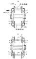
図1において、21は輪軸を車輪8の外側でそれぞれ回転自在に支持する軸箱10を、図15に示したように、モノリンク11を介して台車に支持させたモノリンク式軸箱支持装置を備えた本発明の鉄道車両用台車であり、本発明では、紙面上側に示す車両の最先端および最後端に位置させる輪軸である、たとえば第1軸1および第4軸4を、前述のように軸箱10を介して回転自在に、それぞれ車輪8の外側で支持するモノリンク11が、軸箱10側の間隔より台車21側の間隔が広くなるように、傾斜させて取り付けられている。
In FIG. 1,
このような構成を採用した台車21では、輪軸のヨーイング剛性は以下のようになる。
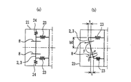
まず、第2軸2と第3軸3のヨーイング剛性K2,3は、従来と同様、図2に示すように、軸箱の前後支持ばね23による前後剛性kxを使用して決定するものであるから、曲線走行時における台車21に対する第2軸2(または第3軸3)の内外軌側の前後変位をx、台車21の中心からモノリンク11と軸箱10(台車21)との取り付け位置までの距離をb0とした場合、
K2,3=2kx・b02
で求めることができる。なお、図2中のθは台車21と第2軸2(または第3軸3)間のヨーイング角を示す。
In the
First, as shown in FIG. 2, the yawing rigidity K2,3 of the
K2,3 = 2kx ・ b0 2
Can be obtained. 2 represents the yawing angle between the
次に、第1軸1と第4軸4のヨーイング剛性K1,4は以下のようになる。
まず、モノリンク11による第1軸1と第4軸4のヨーイング剛性K1m,4mは、図3に示すように、モノリンク11の初期傾斜角をα、台車21の中心からモノリンク11と台車21との取り付け位置までの距離をb1、台車21の中心からモノリンク11と軸箱10との取り付け位置までの距離をb0、モノリンク11の長さをLとした場合、
α=sin{(b1−b0)/L}
であらわすことができる。
Next, the yawing rigidity K1,4 of the
First, the yaw rigidity K1m, 4m of the
α = sin {(b1−b0) / L}
Can be represented.
また、曲線走行時における台車21に対する第1軸1(または第4軸4)の内軌側の左右変位をy1、外軌側の左右変位をy2、曲線走行時における内軌側のモノリンクの傾斜角をβとした場合、
y1=Lsin(α+β)
y2=Lsin(α−β)
であらわすことができる。
In addition, the left-right displacement on the inner rail side of the first shaft 1 (or the fourth shaft 4) with respect to the
y1 = Lsin (α + β)
y2 = Lsin (α-β)
Can be represented.
また、曲線走行時における台車21に対する第1軸1(または第4軸4)の内軌側の前後変位をx1、外軌側の前後変位をx2とした場合、
x1=Lcos(α+β)
x2=Lcos(α−β)
であらわすことができる。
Further, when the longitudinal displacement on the inner rail side of the first shaft 1 (or the fourth shaft 4) with respect to the
x1 = Lcos (α + β)
x2 = Lcos (α-β)
Can be represented.
また、台車21と第1軸1(または第4軸4)間のヨーイング角をθとした場合、
θ=sin〔{(x2−x1)/2}/b0〕≒{(x2−x1)/2}/b0
であらわすことができる。
When the yawing angle between the
θ = sin [{(x2−x1) / 2} / b0] ≈ {(x2−x1) / 2} / b0
Can be represented.
また、台車21と第1軸1(または第4軸4)間の左右変位は(y1−y2)/2であらわすことができる。
したがって、前後支持ばね23の前後剛性をkx、左右支持ばね24の左右剛性をkyとした場合、第1軸1と第4軸4のモノリンク11でのヨーイング剛性K1m,4mは、
K1m,4m=(1/θ)×2ky{(y1−y2)/2}2=2ky・b02・θ/tan2α
であらわすことができる。
Further, the lateral displacement between the
Therefore, when the longitudinal rigidity of the front /
K1m, 4m = (1 / θ) × 2ky {(y1−y2) / 2} 2 = 2ky · b0 2 · θ / tan 2 α
Can be represented.
本発明の第1軸1と第4軸4では、モノリンク11による輪軸ヨーイングと、軸箱10の前後支持ばね23による輪軸ヨーイングが二重に作用する、つまり、直列として作用するため、本発明のモノリンク式軸箱支持装置を備えた台車21における第1軸1と第4軸4の全体としてのヨーイング剛性K1,4は
K1,4=(2kx・b02×2ky・b02/tan2α)/(2kx・b02+2ky・b02/tan2α)=2kx・ky・b02/(kx・tan2α+ky)
となる。
In the
It becomes.
したがって、本発明のモノリンク式軸箱支持装置を備えた台車21における第1軸1と第4軸4の全体としてのヨーイング剛性K1,4は、第2軸2と第3軸3のヨーイング剛性K2,3と比較して、{2kx・ky・b02/(kx・tan2α+ky)}/2kx・b02=kx/(kx・tan2α+ky)倍軟化できることになる。
Therefore, the yawing rigidity K1,4 of the
この第1軸1および第4軸4におけるモノリンク11の傾斜角と、(第1軸1および第4軸4のヨーイング剛性/第2軸2および第3軸3のヨーイング剛性)の関係を図4に示す。この図4より、第1軸1および第4軸4におけるモノリンク11の傾斜角を大きくするほど、ヨーイング剛性が柔らかくなることが分かる。
The relationship between the inclination angle of the
また、図5は、前後剛性を7.5kN/mm、左右剛性を5kN/mm、第1軸および第4軸のモノリンクの傾斜角を50°にした場合に、曲線路の曲率を変化させた場合の曲線通過シミュレーション結果(△印)を示した図である。この図5には同じ前後剛性、左右剛性の台車を使用した場合の従来例の結果(◇印)も併せて示しているが、本発明は全ての曲率において改善されていることが分かる。特に曲率が大きい場合に、外軌横圧低減効果が大きいことが分かる。 In addition, FIG. 5 shows that the curvature of the curved road is changed when the longitudinal rigidity is 7.5 kN / mm, the lateral rigidity is 5 kN / mm, and the inclination angle of the monolink of the first axis and the fourth axis is 50 °. It is the figure which showed the curve passage simulation result (△ mark) in the case of. FIG. 5 also shows the result of the conventional example (marked with ◇) when using the same front and rear rigidity and right and left rigidity carts, and it can be seen that the present invention is improved in all the curvatures. In particular, when the curvature is large, it can be seen that the effect of reducing external lateral pressure is great.
図6および図7はモノリンク式軸箱支持装置を備えた本発明の鉄道車両用台車21の他の例を示したもので、図6(a)は空気ばね座12からモノリンク11を出している例、図6(b)は図6(a)の例において、第1軸1と第4軸4のみならず第2軸2と第3軸3においても、軸箱側の間隔より台車側の間隔が広くなるようにモノリンク11が取り付けられており、かつ、前記間隔を広くすることによって発生するモノリンク11の傾きαが、第1軸1、第4軸4の傾きα1,4を、第2軸2、第3軸3の傾きα2,3よりも大きくなるようにしたものである。
6 and 7 show another example of the
また、図6(c)は第2軸2、第3軸3を回転自在に両側で支持するモノリンク11が、軸箱側の間隔より台車側の間隔が狭くなるように、すなわちモノリンク11の傾きα2,3が負となるように取り付けられている例、図6(d)は第1軸1と第4軸4のモノリンク11の傾きα1,4が正で、第2軸2、第3軸3のモノリンク11の傾きα2,3が負となるように取り付けられている例である。
FIG. 6C shows that the
図7は全ての輪軸1〜4のモノリンク11を同じ角度だけ傾斜させ、第2軸2、第3軸3の左右剛性を、第1軸1、第4軸4の左右剛性よりも大きくすることで、全体としてみた場合、第1軸1と第4軸のヨーイング剛性を柔とした例である。
In FIG. 7, the
以上のように、前後支持剛性が同等の第1軸1〜第4軸4の、車両の最先端および最後端に位置する第1軸1および第4軸4のヨーイング剛性を、これら輪軸の中間に位置する第2軸2および第3軸3のヨーイング剛性より柔となるように支持させることで、片押し式踏面ブレーキを採用する鉄道車両においても、重量増加等を伴わずに、曲線通過性能と直線高速走行性能をともに高い次元で両立することができるようになる。これが本発明の鉄道車両の輪軸支持方法である。
As described above, the yaw rigidity of the
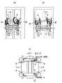
図8は図6(d)の例において、第2軸2、第3軸3のモノリンク11と車体5をリンク22で連結し、輪軸を強制操舵可能に構成した例を示したものである。この本発明の鉄道車両では、自己操舵機能に加えて強制操舵も行えるようになって、曲線通過性能の更なる向上が図れる。
FIG. 8 shows an example in which the
なお、以上のモノリンク式軸箱支持装置を備えた本発明の鉄道車両用台車21の場合、モノリンクゴムブッシュの上下変位に対する耐久性を保つため、モノリンク11の長さLは300mm以上とすることが望ましい。
In the case of the
本発明は前述のモノリンク式軸箱支持装置を備えた本発明の鉄道車両用台車21に限らず、図9に示したような、軸はり32を介して台車に支持させた軸はり式軸箱支持装置を備えた本発明の鉄道車両用台車31であっても良い。
The present invention is not limited to the
この軸はり式軸箱支持装置を備えた本発明の鉄道車両用台車31では、前後支持剛性が同等の第1軸1〜第4軸4の、第1軸1および第4軸4のヨーイング剛性を、第2軸2および第3軸3のヨーイング剛性より柔となるように支持させるためには、図9に示したように、第1軸1および第4軸4を、軸箱10を介してそれぞれの車輪8の外側で支持する軸はり32の、両軸はり緩衝ゴム33の間隔Aが、車両の前記中間に位置させる第2軸2および第3軸3を、軸箱10を介してそれぞれの車輪8の外側で支持する軸はり32の、両軸はり緩衝ゴム33の間隔Bに比べて、狭くなるように取り付ければよい。
In the
このような構成を採用した台車31では、輪軸のヨーイング剛性は以下のようになる。
まず、第1軸1と第4軸4のヨーイング剛性K1,4は、図10に示すように、前後剛性をkx、曲線走行時における台車31に対する第1軸1(または第4軸4)の内外軌側の前後変位をx、軸はり32と軸箱10(台車31)との両取り付け位置間の距離(=前記間隔A)を2b0とした場合、
K1,4=2kx・b02
で求めることができる。
In the
First, as shown in FIG. 10, the yaw stiffness K1,4 of the
K1,4 = 2kx ・ b0 2
Can be obtained.
また、第2軸2と第3軸3のヨーイング剛性K2,3は、図10に示すように、前後剛性をkx、曲線走行時における台車31に対する第2軸2(または第3軸3)の内外軌側の前後変位をx、軸はり32と台車31との両取り付け位置間の距離(=前記間隔B)を2c0とした場合、
K2,3=2kx・c02
で求めることができる。
Further, as shown in FIG. 10, the yawing rigidity K2,3 of the
K2,3 = 2kx ・ c0 2
Can be obtained.
したがって、本発明の軸はり式軸箱支持装置を備えた台車31における第1軸1と第4軸4のヨーイング剛性K1,4と、第2軸2と第3軸3のヨーイング剛性K2,3の比は、(b0/c0)2となる。
Therefore, the yawing stiffness K1,4 of the
軸はり式軸箱支持装置を備えた台車31の第1軸1、第4軸4と第2軸2、第3軸の支持間隔の比(=b0/c0)と、前記ヨーイング剛性の比を図11に示す。この図11より、第1軸1、第4軸4と第2軸2、第3軸の支持間隔の比(=b0/c0)が小さくなるほど、すなわち、第2軸2、第3軸3の軸はり32の、台車31側の間隔が広くなるほど、第2軸2、第3軸3のヨーイング剛性が大きくなることが分かる。
The ratio of the support intervals of the
これより、第1軸1、第4軸4の前後剛性を現状に保ちつつ、第2軸2、第3軸の前後剛性を大きくすることが可能になって、図12に示したように、現状の曲線通過性能を維持しつつ、高速安定性を向上することができることが分かる。
As a result, it is possible to increase the longitudinal rigidity of the
本発明は上記の例に限らず、図13に示したように、軸箱10側の間隔より台車側の間隔が広くなるようにモノリンク11を取り付けたモノリンク式の軸箱支持装置と、軸箱10側の間隔より台車側の間隔が広くなるように軸はり32を取り付けた軸はり式の軸箱支持装置を混在させて使用した台車41でも良いなど、各請求項に記載された技術的思想の範囲内で、適宜実施の形態を変更しても良いことは、言うまでもない。
The present invention is not limited to the above example, and as shown in FIG. 13, a monolink-type axle box support device in which the
以上の本発明は、片押し式踏面ブレーキを備えた鉄道車両用台車に限らず、ディスクブレーキを備えた鉄道車両用台車にも適用できる。 The present invention described above can be applied not only to a railway vehicle carriage provided with a one-push tread brake, but also to a railway vehicle carriage provided with a disc brake.
1 第1軸
2 第2軸
3 第3軸
4 第4軸
5 車体
10 軸箱
11 モノリンク
21、31、41 台車
22 リンク
32 軸はり
33 軸はり緩衝ゴム
DESCRIPTION OF
Claims (8)
前記輪軸のすべてにおいて前後支持剛性を同等とし、
かつ、前記車両の最先端および最後端に位置する輪軸のヨーイング剛性を、これら輪軸の中間に位置する輪軸のヨーイング剛性より柔となるように支持することを特徴とする鉄道車両の輪軸支持方法。 A method of supporting a wheel shaft in a railway vehicle that supports a vehicle with a plurality of carriages having a plurality of wheel shafts,
The front and rear support rigidity is the same for all the wheel shafts,
A method for supporting a wheel shaft of a railway vehicle, comprising: supporting yawing rigidity of a wheel shaft positioned at a forefront and a rear end of the vehicle so as to be softer than a yawing rigidity of a wheel shaft positioned between the wheel shafts.
前記輪軸のすべてにおいて前後支持剛性が同等であり、
かつ、前記複数の輪軸のうち両端に位置する輪軸のいずれかのヨーイング剛性が、その他の輪軸のヨーイング剛性よりも柔となるように支持されていることを特徴とする鉄道車両用台車。 A carriage with a plurality of wheel shafts,
The front and rear support rigidity is the same in all of the wheel shafts,
In addition, the bogie for a railway vehicle is supported such that the yawing rigidity of any of the plurality of wheel shafts located at both ends is more flexible than the yawing rigidity of the other wheel shafts.
該台車がモノリンク式軸箱支持装置を備え、
前記複数の輪軸のうち両端に位置する何れかの輪軸を、軸箱を介してそれぞれの車輪の外側で支持するモノリンクが、軸箱側の間隔より台車側の間隔が広くなるように取り付けられていることを特徴とする鉄道車両用台車。 A carriage for a railway vehicle according to claim 2,
The carriage includes a monolink type axle box support device,
A monolink that supports any one of the plurality of wheel shafts located at both ends on the outside of each wheel via a shaft box is attached so that the distance on the cart side is wider than the distance on the wheel side. A railcar bogie characterized by the above.
該台車がモノリンク式軸箱支持装置を備え、
前記複数の輪軸のうち両端に位置する何れかの輪軸以外の輪軸を、軸箱を介してそれぞれの車輪の外側で支持するモノリンクが、軸箱側の間隔より台車側の間隔が狭くなるように取り付けられていることを特徴とする鉄道車両用台車。 A carriage for a railway vehicle according to claim 2,
The carriage includes a monolink type axle box support device,
The monolink that supports the wheel shafts other than one of the plurality of wheel shafts other than the wheel shafts on the outer side of each wheel via the axle box is configured such that the distance on the carriage side is narrower than the distance on the axle box side. A railcar bogie characterized by being attached to the railcar.
該台車がモノリンク式軸箱支持装置を備え、
輪軸を、軸箱を介してそれぞれの車輪の外側で支持するモノリンクの、軸箱側の間隔と台車側の間隔とを異ならせ、かつ、前記間隔を異ならせることによって発生するモノリンクの傾きが、軸箱側の間隔より台車側の間隔が広くなるように取り付けた場合を正、狭くなるように取り付けた場合を負とした場合、前記複数の輪軸のうち両端に位置する何れかの輪軸を支持するモノリンクの傾きから、その他の輪軸を支持するモノリンクの傾きを差し引いた差が0よりも大きくなるようにモノリンクが取り付けられていることを特徴とする鉄道車両用台車。 A carriage for a railway vehicle according to claim 2,
The carriage includes a monolink type axle box support device,
The inclination of the monolink that occurs when the distance between the axle box side and the carriage side of the monolink that supports the wheel shaft on the outside of each wheel via the axle box is different and the distance is different. However, when the mounting is performed so that the space on the carriage side is wider than the space on the side of the axle box, and when the mounting is performed so that the space is narrower, any of the plurality of wheel shafts is positioned at both ends. A railcar carriage characterized in that the monolink is attached so that a difference obtained by subtracting the inclination of the monolink supporting the other wheel shaft from the inclination of the monolink supporting the wheel is larger than zero.
該台車が軸はり式軸箱支持装置を備え、
前記複数の輪軸のうち両端に位置する何れかの輪軸を、軸箱を介してそれぞれの車輪の外側で支持する軸はりの、両軸はり緩衝ゴムの間隔が、
その他の輪軸を、軸箱を介してそれぞれの車輪の外側で支持する軸はりの、両軸はり緩衝ゴムの間隔に比べて、狭くなるように取り付けられていることを特徴とする鉄道車両用台車。 A carriage for a railway vehicle according to claim 2,
The carriage is provided with a shaft beam type axle box support device,
Of the plurality of wheel shafts, any one of the wheel shafts located at both ends, the shaft beam that supports the outside of each wheel via a shaft box, the distance between the two beam buffer rubbers,
A railcar bogie characterized in that it is mounted so as to be narrower than the distance between the shock-absorbing rubbers of the shaft beams that support the other wheel shafts on the outside of each wheel via a shaft box. .
前記複数の輪軸のうち両端に位置する何れかの輪軸を、軸箱を介してそれぞれの車輪の外側で支持するモノリンクと、
その他の輪軸を、軸箱を介してそれぞれの車輪の外側で支持する軸はりを備え、
前記モノリンクが、軸箱側の間隔より台車側の間隔が広くなるように取り付けられる一方、前記軸はりは、軸箱側の間隔より台車側の間隔が広くなるように取り付けられていることを特徴とする鉄道車両用台車。 A carriage for a railway vehicle according to claim 2,
A monolink for supporting any one of the plurality of wheel shafts at both ends of the plurality of wheel shafts on the outside of each wheel via a shaft box;
Axial beams that support other wheel axles on the outside of each wheel via axle boxes,
The monolink is attached so that the distance on the carriage side is wider than the distance on the axle box side, while the axle beam is attached so that the distance on the carriage side is wider than the distance on the axle box side. A featured railcar bogie.
前記モノリンクと車体をリンクで連結し、輪軸を強制操舵可能に構成したことを特徴とする鉄道車両。
A railway vehicle comprising the carriage according to any one of claims 3 to 5,
A railway vehicle characterized in that the monolink and the vehicle body are connected by a link so that the wheel shaft can be forcibly steered.
Priority Applications (1)
| Application Number | Priority Date | Filing Date | Title |
|---|---|---|---|
| JP2004290413A JP4356576B2 (en) | 2004-10-01 | 2004-10-01 | Railway vehicle wheel shaft support method, railcar bogie, and railcar |
Applications Claiming Priority (1)
| Application Number | Priority Date | Filing Date | Title |
|---|---|---|---|
| JP2004290413A JP4356576B2 (en) | 2004-10-01 | 2004-10-01 | Railway vehicle wheel shaft support method, railcar bogie, and railcar |
Publications (2)
| Publication Number | Publication Date |
|---|---|
| JP2006103424A JP2006103424A (en) | 2006-04-20 |
| JP4356576B2 true JP4356576B2 (en) | 2009-11-04 |
Family
ID=36373621
Family Applications (1)
| Application Number | Title | Priority Date | Filing Date |
|---|---|---|---|
| JP2004290413A Active JP4356576B2 (en) | 2004-10-01 | 2004-10-01 | Railway vehicle wheel shaft support method, railcar bogie, and railcar |
Country Status (1)
| Country | Link |
|---|---|
| JP (1) | JP4356576B2 (en) |
Families Citing this family (5)
| Publication number | Priority date | Publication date | Assignee | Title |
|---|---|---|---|---|
| JP5259999B2 (en) * | 2007-08-03 | 2013-08-07 | 新日鐵住金株式会社 | Axle box support device for bogie for high-speed railway vehicles |
| JP5010629B2 (en) * | 2009-02-20 | 2012-08-29 | 三菱重工業株式会社 | Low floor vehicle |
| JP5562881B2 (en) * | 2011-02-18 | 2014-07-30 | 三菱重工業株式会社 | Railway vehicle |
| JP5562882B2 (en) * | 2011-02-18 | 2014-07-30 | 三菱重工業株式会社 | Railway vehicle |
| JP7406088B2 (en) | 2020-02-13 | 2023-12-27 | 日本製鉄株式会社 | Railway vehicle bogies and railway vehicles equipped with the bogies |
-
2004
- 2004-10-01 JP JP2004290413A patent/JP4356576B2/en active Active
Also Published As
| Publication number | Publication date |
|---|---|
| JP2006103424A (en) | 2006-04-20 |
Similar Documents
| Publication | Publication Date | Title |
|---|---|---|
| KR101297938B1 (en) | Bogie for track-guided vehicle | |
| US10065663B2 (en) | Steering bogie and vehicle | |
| JP5010630B2 (en) | Low floor vehicle | |
| US10131367B2 (en) | Steering bogie, and vehicle for track-based transportation system | |
| JP3448445B2 (en) | Steering device for bogies for railway vehicles | |
| JP4356576B2 (en) | Railway vehicle wheel shaft support method, railcar bogie, and railcar | |
| KR101772606B1 (en) | 3 axle bogie for railway car | |
| JP4838693B2 (en) | Track system | |
| JPS60229860A (en) | Truck for railway rolling stock | |
| JP2021130363A (en) | Link device for railroad vehicle and bogie | |
| JP2738114B2 (en) | Two-axle bogies for railway vehicles | |
| JP4967358B2 (en) | Rail car axle box support device and rail car bogie | |
| JP6275403B2 (en) | Railway vehicle carriage, railway vehicle and railway system | |
| KR101236534B1 (en) | Monorail bogie assay with complex suspension system of coil-spring module | |
| RU2313464C1 (en) | Railway vehicle axle-box | |
| KR101329001B1 (en) | Independence rotating wheels suspension apparatus for low-floor vehicle | |
| JP7212789B2 (en) | Bogie for railway vehicle | |
| JP5836073B2 (en) | Bogie bogie and track system vehicle equipped with the bogie bogie | |
| JP2008230488A (en) | Axle box supporting device of bogie for railway vehicle, and bogie | |
| JPS604460A (en) | Truck for railway rolling stock | |
| JP2008007042A (en) | Axle box supporting device for railroad vehicle | |
| JPH0417814B2 (en) | ||
| JP6985945B2 (en) | Bogie for railroad cars | |
| JP2006151078A (en) | Railway vehicle | |
| JP4742946B2 (en) | Rail car axle box support device |
Legal Events
| Date | Code | Title | Description |
|---|---|---|---|
| A621 | Written request for application examination |
Free format text: JAPANESE INTERMEDIATE CODE: A621 Effective date: 20061018 |
|
| A977 | Report on retrieval |
Free format text: JAPANESE INTERMEDIATE CODE: A971007 Effective date: 20090331 |
|
| A131 | Notification of reasons for refusal |
Free format text: JAPANESE INTERMEDIATE CODE: A131 Effective date: 20090421 |
|
| A521 | Written amendment |
Free format text: JAPANESE INTERMEDIATE CODE: A523 Effective date: 20090615 |
|
| TRDD | Decision of grant or rejection written | ||
| A01 | Written decision to grant a patent or to grant a registration (utility model) |
Free format text: JAPANESE INTERMEDIATE CODE: A01 Effective date: 20090714 |
|
| A01 | Written decision to grant a patent or to grant a registration (utility model) |
Free format text: JAPANESE INTERMEDIATE CODE: A01 |
|
| A61 | First payment of annual fees (during grant procedure) |
Free format text: JAPANESE INTERMEDIATE CODE: A61 Effective date: 20090727 |
|
| FPAY | Renewal fee payment (event date is renewal date of database) |
Free format text: PAYMENT UNTIL: 20120814 Year of fee payment: 3 |
|
| R150 | Certificate of patent or registration of utility model |
Ref document number: 4356576 Country of ref document: JP Free format text: JAPANESE INTERMEDIATE CODE: R150 Free format text: JAPANESE INTERMEDIATE CODE: R150 |
|
| FPAY | Renewal fee payment (event date is renewal date of database) |
Free format text: PAYMENT UNTIL: 20120814 Year of fee payment: 3 |
|
| FPAY | Renewal fee payment (event date is renewal date of database) |
Free format text: PAYMENT UNTIL: 20130814 Year of fee payment: 4 |
|
| FPAY | Renewal fee payment (event date is renewal date of database) |
Free format text: PAYMENT UNTIL: 20130814 Year of fee payment: 4 |
|
| S111 | Request for change of ownership or part of ownership |
Free format text: JAPANESE INTERMEDIATE CODE: R313111 |
|
| FPAY | Renewal fee payment (event date is renewal date of database) |
Free format text: PAYMENT UNTIL: 20130814 Year of fee payment: 4 |
|
| R350 | Written notification of registration of transfer |
Free format text: JAPANESE INTERMEDIATE CODE: R350 |
|
| S533 | Written request for registration of change of name |
Free format text: JAPANESE INTERMEDIATE CODE: R313533 |
|
| R350 | Written notification of registration of transfer |
Free format text: JAPANESE INTERMEDIATE CODE: R350 |