JP4356325B2 - Inkjet recording device - Google Patents
Inkjet recording device Download PDFInfo
- Publication number
- JP4356325B2 JP4356325B2 JP2003016643A JP2003016643A JP4356325B2 JP 4356325 B2 JP4356325 B2 JP 4356325B2 JP 2003016643 A JP2003016643 A JP 2003016643A JP 2003016643 A JP2003016643 A JP 2003016643A JP 4356325 B2 JP4356325 B2 JP 4356325B2
- Authority
- JP
- Japan
- Prior art keywords
- light
- ink
- light source
- film
- platen
- Prior art date
- Legal status (The legal status is an assumption and is not a legal conclusion. Google has not performed a legal analysis and makes no representation as to the accuracy of the status listed.)
- Expired - Fee Related
Links
- 238000004804 winding Methods 0.000 claims description 34
- 238000010538 cationic polymerization reaction Methods 0.000 claims description 8
- 238000001514 detection method Methods 0.000 claims description 5
- 238000007599 discharging Methods 0.000 claims description 3
- 230000001678 irradiating effect Effects 0.000 claims description 3
- 230000005540 biological transmission Effects 0.000 description 34
- 238000001723 curing Methods 0.000 description 20
- 238000006243 chemical reaction Methods 0.000 description 14
- 230000015572 biosynthetic process Effects 0.000 description 11
- 239000003595 mist Substances 0.000 description 5
- 230000007423 decrease Effects 0.000 description 4
- 238000012423 maintenance Methods 0.000 description 4
- 239000000463 material Substances 0.000 description 4
- 238000010586 diagram Methods 0.000 description 3
- 230000000694 effects Effects 0.000 description 3
- 238000007639 printing Methods 0.000 description 3
- 230000035945 sensitivity Effects 0.000 description 3
- 238000003860 storage Methods 0.000 description 3
- 239000002699 waste material Substances 0.000 description 3
- 230000001939 inductive effect Effects 0.000 description 2
- 238000004519 manufacturing process Methods 0.000 description 2
- 238000000034 method Methods 0.000 description 2
- 238000000016 photochemical curing Methods 0.000 description 2
- 230000000704 physical effect Effects 0.000 description 2
- 238000010526 radical polymerization reaction Methods 0.000 description 2
- 239000011358 absorbing material Substances 0.000 description 1
- 238000010894 electron beam technology Methods 0.000 description 1
- 238000007646 gravure printing Methods 0.000 description 1
- 230000020169 heat generation Effects 0.000 description 1
- QSHDDOUJBYECFT-UHFFFAOYSA-N mercury Chemical compound [Hg] QSHDDOUJBYECFT-UHFFFAOYSA-N 0.000 description 1
- 229910052753 mercury Inorganic materials 0.000 description 1
- 229910052751 metal Inorganic materials 0.000 description 1
- 239000002184 metal Substances 0.000 description 1
- 229910052987 metal hydride Inorganic materials 0.000 description 1
- 150000004681 metal hydrides Chemical class 0.000 description 1
- 150000002739 metals Chemical class 0.000 description 1
- 239000005022 packaging material Substances 0.000 description 1
- 238000004806 packaging method and process Methods 0.000 description 1
- 230000000149 penetrating effect Effects 0.000 description 1
- 229920005989 resin Polymers 0.000 description 1
- 239000011347 resin Substances 0.000 description 1
- 230000007723 transport mechanism Effects 0.000 description 1
Images


Landscapes
- Ink Jet (AREA)
Description
【0001】
【発明の属する技術分野】
本発明は、インクジェット記録装置に係り、特に光硬化性のインクを使用したインクジェット記録装置に関する。
【0002】
【従来の技術】
一般に、インクジェット記録装置は印刷時の騒音が比較的小さく、印字の品質が良好であるため、現在、数多く使用されている。
インクジェット記録装置は、例えばピエゾ素子やヒータ素子等を用いて、記録ヘッドのノズルからインクを微小な液滴として紙等の記録媒体に向けて吐出し、記録媒体にインクを浸透若しくは定着させながら、記録ヘッドと記録媒体の相対的な位置を移動させることにより、記録媒体に画像を形成する。
インクジェット記録装置には、例えば、記録媒体上で記録ヘッドを往復移動させ、記録ヘッドの走査方向と直交する方向に記録媒体を搬送させることにより画像を形成するシリアルヘッド方式のものや、記録媒体の記録幅にわたるノズル列を有して固定された記録ヘッドを持ち、記録媒体を記録幅の方向に直交する方向に搬送させることにより画像を形成するラインヘッド方式のものがある。
【0003】
現在、商品や商品の包装材への印刷等の分野では、少量生産のニーズが高まっており、グラビア印刷方式やフレキソ印刷方式など製版を必要とする方式に比して少量を低コストに生産できるインクジェット方式の利用が展開している。
良く知られるように商品や商品の包装材には樹脂や金属などのインク吸収性のない材料が用いられることが少なくない。
このようなインク吸収性のない材料を記録媒体とするとき、記録媒体へのインクの定着を可能とするため、高粘度の光硬化性のインクを記録媒体上に吐出して付着させた後、紫外線等の光を照射することでインクを硬化定着させる光硬化方式のインクジェット記録装置が開発されている。
【0004】
従来、このような光硬化方式のインクジェット記録装置として、ラジカル重合系のインクを用い、多量の紫外線を一括に照射する構成とした紫外線硬化型のインクジェット記録装置が実用化されている(例えば、特許文献1参照)。
【0005】
【特許文献1】
特開2002−144555号公報
【0006】
【発明が解決しようとする課題】
しかしながら、上記したようにラジカル重合系のインクを用いると、比較的多量の紫外線照射が必要となる。そのため、高出力の光源装置を搭載することとなって装置の長大化、装置の製造コストの増大を招くという問題がある。
この問題を解決するため、現在実用化されていないカチオン重合系のインクを採用することが考えられるが、カチオン重合系のインクは湿度依存性等の不安定な物性があるとともに、反射光等の弱い光により硬化反応する物性があるため取り扱いが難しく、実用化を困難にさせている。
【0007】
例えば、装置の小型化等の要請により光源を記録ヘッドに近づければ近づけるほど、インクミストが光源に付着しやすくなる。そして、付着したインクミストは、光源からの光を受けてその位置で硬化してしまう。インクが付着し硬化すると、その分照度が低下するために、付着したインクを除去するか、光源を交換するなどして、インク硬化に必要な照度を確保しなければならない。しかしながら、光源からインクを除去するには、光源上で硬化しているためにメンテナンスに時間がかかってしまう。一方、光源を交換してしまうと、光源自体の寿命がつきる前に交換することになり、その分光源が無駄となってしまう。
【0008】
本発明の課題は、光源に対するインクミストの影響を低減することで、効率的に画像形成が行えるインクジェット記録装置を提供することである。
【0009】
【課題を解決するための手段】
請求項1記載の発明のインクジェット記録装置は、
吐出口から記録媒体に光硬化型のインクを吐出する記録ヘッドと、
前記記録媒体を前記記録ヘッドの吐出面に対向するように支持するプラテンと、
前記記録ヘッドから吐出された前記インクに対して光を照射し、前記インクを硬化させる光源と、
前記光源の前記プラテン側を覆って、前記光源からの光を透過する長尺な光透過フィルムと、
前記光源の一側方でローラ状に巻かれた前記光透過フィルムを、前記プラテンと前記光源との間を搬送経路として間欠的に巻き取るフィルム巻取装置と、
を備え、
前記光透過フィルムは、400nm以下の波長域の光及び740nm以上の波長域の光を透過することを特徴としている。
【0010】
請求項1記載の発明によれば、光透過フィルムが、光源のプラテン側、つまり光源の照射方向の前方を覆っているので、光を透過しながらも光源へのインクの付着を防止できる。このため、光源自体にはインクが付着しにくくなるので、光源が寿命を迎えたときにだけ交換すればよく、光源を無駄にすることがなくなる。
また、光透過フィルムは、フィルム巻取装置によって間欠的に巻き取られているので、光透過フィルムに対するインクの付着によって照度が低下した場合においても、光透過フィルムを巻き取ることで、光透過フィルムのインクの付着していない部分が光源の照射方向の前方に配置されて、硬化反応に必要な照度を確保することができる。このように、光源を交換しなくても照度が確保できるので、メンテナンスにも時間がかからず、効率的に画像形成を行うことができる。
そして、光透過フィルムがローラ状に巻かれているので、長期にわたって光透過フィルムを交換しなくても、硬化反応に必要な照度を維持することができる。
そして、請求項1記載の発明によれば、光透過フィルムが400nm以下の波長域の光を透過するので、インクが紫外線で硬化する紫外線硬化型のインクである場合には、記録媒体にインクを安定して定着させることができる。
ここで、740nm以上の波長域の光は、いわゆる赤外線であるために熱作用が大きい。このため、光透過フィルムが赤外線を透過しないとフィルム巻取装置内に熱がこもり、装置自体の温度上昇を誘発するおそれがある。フィルム巻取装置自体が加熱されると、その近傍に配置された記録ヘッドに対しても熱が伝わることになり、記録ヘッド内のインクも加熱され、安定したインク吐出が困難となる。しかしながら、請求項1記載の発明によれば、光透過フィルムが740nm以上の波長域の光も透過するので、フィルム巻取装置内に熱が篭もることを防止でき、結果として安定したインク吐出を維持することができる。
【0011】
請求項2記載の発明は、請求項1記載のインクジェット記録装置において、
前記光透過フィルムを介して前記光源に対向するように前記プラテンに設けられた光量センサを備え、
前記フィルム巻取装置は、前記光量センサの検出結果に基づいて、前記光透過フィルムの巻き取りを開始させる制御部を備えることを特徴としている。
【0012】
請求項2記載の発明によれば、制御部が、光量センサの検出結果に基づいて、光透過フィルムの巻き取りを開始させるので、硬化反応に必要な照度が得られない値を光量センサが検出した際に、光透過フィルムの巻き取りを開始させれば、硬化反応に必要な照度を維持しながら光透過フィルムを無駄なく使用することが可能となる。
【0017】
請求項3記載の発明は、請求項1又は2記載のインクジェット記録装置において、
前記インクとしてカチオン重合系インクが用いられることを特徴としている。
【0018】
請求項3記載の発明によれば、カチオン重合系インクのような比較的低出力の光源により硬化する硬化感度の高いインクを用いるので、低出力の光源の使用が可能となって、装置の小型化、コストの低減化を図ることができる。
【0019】
【発明の実施の形態】
以下、この発明の実施の形態について、図1〜図4の図面を参照しながら説明する。図1は、本実施形態におけるインクジェット記録装置1の概略構成図である。
【0020】
インクジェット記録装置1は、記録媒体の搬送方向に対して直交する方向に記録ヘッドを走査させながら、カチオン重合系インクにより画像を形成するシリアル方式のインクジェット記録装置である。このインクジェット記録装置1には、記録媒体を下方から支持するプラテン2が設けられており、プラテン2の上方には、記録媒体の搬送方向に対して直交する方向に走査するキャリッジ3が設けられている。
【0021】
キャリッジ3には、各色毎のインク(Y:イエロー、M:マゼンタ、C:シアン、K:ブラック)を吐出する複数の記録ヘッド4が、プラテン2により支持された記録媒体と吐出面41とが対向するように搭載されている。この記録ヘッド4の吐出面41には、インクを吐出する複数の吐出口が、記録媒体の搬送方向に沿って直線状に配列されている。
また、キャリッジ3には、記録ヘッド4の両側方に位置するように、記録媒体に着弾したインクを硬化させるための光照射装置5が設けられている。
【0022】
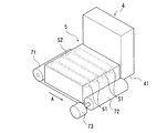
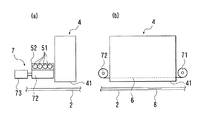
以下、図2及び図3を参照にして、光照射装置5について詳細に説明する。図2は、光照射装置5の概略構成を表す斜視図である。また、図3(a)は、光照射装置5の概略構成を表す正面図であり、図3(b)は側面図である。
光照射装置5には、図2及び図3に示すように、記録媒体に対して光を照射する、例えば指向性のない棒状の光源51が、吐出口の列方向に対して略平行に並ぶように複数列、配置されている。
【0023】
ここで、光源51としては、紫外線、電子線、X線、可視光、赤外光などを照射する様々な光源を用いることが可能であるが、硬化性、コスト等を考慮すると紫外線を照射する光源が好ましい。そして、指向性のない紫外線を照射する光源としては、例えば、蛍光灯、水銀ランプ、メタルハイドランプ等が挙げられる。また指向性のある紫外線を照射する光源としては、例えばLED、紫外線レーザが挙げられる。
【0024】
そして、光照射装置5には、光源51の照射方向の前方を開口した状態で光源51を覆うカバー部材52が設けられている。カバー部材52の内面は、散乱した光が反射して照射方向に向かうように、鏡面加工が施されている。カバー部材52の下方には、カバー部材52の開口を覆うことで、光源51のプラテン2側を覆い、光源51からの光を透過する光透過フィルム6が配置されている。つまり、この光透過部材53により、画像形成中に発生したインクミストが光源51に付着することを防止している。
【0025】
光照射装置5には、長尺な光透過フィルム6をプラテン2と光源51との間を搬送経路として間欠的に巻き取るフィルム巻取装置7が設けられている。
フィルム巻取装置7には、図2及び図3に示すように、カバー部材52に対して記録媒体の搬送方向における後方側でローラ状に巻かれた光透過フィルム6を保持する保持ローラ71が設けられている。また、カバー部材52を介して保持ローラ71と対向する巻取ローラ72が、保持ローラ71で保持された光透過フィルム6を巻き取るように配置されている。この巻取ローラ72には、駆動源となるモータ73が連結されている。
【0026】
また、フィルム巻取装置7には、図3(b)に示すように、光透過フィルム6を透過した光の光量を検出する光量センサ8が、光透過フィルム6を介して光源51と対向するようにプラテン2に設けられている。
【0027】
光透過フィルム6は、光源51からの光を透過し、インクの侵入を遮断できる材料から形成されている。特に、本実施形態のように、光源51が紫外線を照射するものである場合には400nm以下の波長域の光を透過する材料から形成されていることが好ましい。これにより紫外線硬化型のインクを、記録媒体に安定して定着させることができる
さらに、光照射装置5自体の発熱を考慮するのであれば、400nm以下の波長域の光を透過するとともに、740nm以上の波長域の光も透過する材料から形成されていることが好ましく、こうすることで、フィルム巻取装置7内に熱が篭もることを防止でき、結果として安定したインク吐出を維持することができる。
【0028】
次に、図4を参照してインクジェット記録装置1における主制御部分について説明する。図4はインクジェット記録装置1の主制御部分を表すブロック図である。
【0029】
インクジェット記録装置1には、各駆動部を制御する制御部10が設けられている。制御部10には、画像形成時における指示が入力される入力部11、記録媒体の搬送機構9、キャリッジ3のキャリッジ駆動源31、記憶部12、記録ヘッド4、光源51、モータ73、光量センサ8が電気的に接続されている。なお、制御部10には、これら以外にもインクジェット記録装置1の各駆動部などが接続されている。
【0030】
そして、制御部10は、入力部11からの指示に基づいて、記憶部12中に書き込まれている制御プログラムや制御データに従い各種機器を制御するようになっている。
記憶部12には、記録媒体に付着したインクが好適に硬化反応するのに必要で、かつ光透過フィルム6の巻き取り開始の基準となる光量値が記録媒体の種類毎、インクの種類毎に記憶されている。
【0031】
次に、本実施形態に係るインクジェット記録装置1の動作について説明する。
【0032】
先ず、作業者は、画像形成に用いられる記録媒体の種類及びインクの種類を入力部から入力してから、画像形成の開始を入力する。この入力に基づいて、制御部10は、キャリッジ3を走査させて、光源51を点灯させながら、記録ヘッド4からインクを吐出させ、画像形成が完了するまでこの動作を繰り返させる。
画像形成が繰り返し行われる際に、光量センサ8が、光透過フィルム6を透過した光の光量を検出すると、制御部10は、検出された光量値と、画像形成に用いられる記録媒体及びインクに応じた光量値とを比較して、検出された光量値の方が大きい場合には、フィルム巻取装置7のモータ73を停止させたままで画像形成を継続する。
【0033】
一方、検出された光量値の方が小さい場合には、光透過フィルム6がインクミストによって汚れ、好適な硬化反応を示しにくくなっているので、制御部10は、光量センサ8の検出結果に基づいてモータ73を駆動させ、光透過フィルム6の巻き取りを開始する。これにより、光透過フィルム6の汚れた部分は、記録媒体の搬送方向(図2の矢印A)に沿いながら巻き取られて、カバー部材52の開口部分から除去される。この巻き取りに伴って、カバー部材52の開口部分には光透過フィルム6のインクの付着していない部分が新たに配置される。そして、光透過フィルム6の汚れた部分、つまり巻き取り以前に、カバー部材52の開口を覆っていた部分が、カバー部材52の開口から除外されると、制御部10は、モータ73を停止して、画像形成を再開する。これにより、インクの硬化に必要なだけの照度が確保される。
【0034】
以上のように、本実施形態のインクジェット記録装置1によれば、光透過フィルム6が、光源51のプラテン2側、つまり光源51の照射方向の前方を覆っているので、光を透過しながらも光源51へのインクの付着を防止できる。このため、光源51自体にはインクが付着しにくくなり、光源51が寿命を迎えたときにだけ交換すればよく、光源51を無駄にすることがなくなる。
また、光透過フィルム6は、フィルム巻取装置7によって間欠的に巻き取られているので、光透過フィルム6に対するインクの付着によって照度が低下した場合においても、光透過フィルム6を巻き取ることで、光透過フィルム6のインクの付着していない部分が光源51の照射方向の前方に配置されて、硬化反応に必要な照度を確保することができる。このように、光源51を交換しなくても照度が確保できるので、メンテナンスにも時間がかからず、効率的に画像形成を行うことができる。
そして、光透過フィルム6がローラ状に巻かれているので、長期にわたって光透過フィルム6を交換しなくても、硬化反応に必要な照度を維持することができる。
【0035】
また、制御部10が、光量センサ8の検出結果に基づいて、光透過フィルム6の巻き取りを開始させるので、硬化反応に必要な照度を維持しながら光透過フィルム6を無駄なく使用することが可能となる。
【0036】
そして、光透過フィルム6が400nm以下の波長域の光を透過するので、紫外線で硬化する紫外線硬化型のインクを、記録媒体に安定して定着させることができる。
ここで、740nm以上の波長域の光は、いわゆる赤外線であるために熱作用が大きい。このため、光透過フィルムが赤外線を透過しないとフィルム巻取装置7内に熱がこもり、装置自体の温度上昇を誘発するおそれがある。フィルム巻取装置7自体が加熱されると、その近傍に配置された記録ヘッド4に対しても熱が伝わることになり、記録ヘッド4内のインクも加熱され、安定したインク吐出が困難となる。しかしながら、本実施形態では光透過フィルムが740nm以上の波長域の光も透過するので、フィルム巻取装置7内に熱が篭もることを防止でき、結果として安定したインク吐出を維持することができる。
また、カチオン重合系インクのような比較的低出力の光源により硬化する硬化感度の高いインクが用いられていると、低出力の光源の使用が可能となって、装置の小型化、コストの低減化を図ることができる。
【0037】
なお、本発明は上記実施の形態に限らず適宜変更可能であるのは勿論である。
例えば、本実施形態では、シリアル方式のインクジェット記録装置1を例示して説明したが、本発明の構成は、記録ヘッドとしてラインヘッドが用いられるラインヘッド方式のインクジェット記録装置に適用することも可能である。
また、本実施形態では、ローラ状に巻かれた光透過フィルム6を、カバー部材52に対して記録媒体の搬送方向における後方側に配置することで、光源51の一側方に配置する構成を例示したが、巻き取る際に光源51のプラテン2側を覆うことが可能であれば、ローラ状に巻かれた光透過フィルム6を光源51のいずれの側方に配置してもよい。例えば、カバー部材52に対して記録媒体の搬送方向における前方側であってもよい。
【0038】
また、本実施形態では、記録媒体の搬送方向と光透過フィルム6の搬送方向とが沿うように構成されているが、巻き取る際に光源51のプラテン2側を覆うことが可能であれば、両者の方向が同方向でなくともよく、さらには、カバー部材52の内部に保持ローラ及び巻取ローラの少なくとも一方を配置する構成であってもよい。
【0039】
【発明の効果】
請求項1記載の発明によれば、光を透過しながらも光源へのインクの付着を防止できる。このため、光源自体にはインクが付着しにくくなるので、光源が寿命を迎えたときにだけ交換すればよく、光源を無駄にすることがなくなる。
また、光透過フィルムに対するインクの付着によって照度が低下した場合においても、光透過フィルムを巻き取ることで、光透過フィルムのインクの付着していない部分が光源の照射方向の前方に配置されて、硬化反応に必要な照度を確保することができる。このように、光源を交換しなくても照度が確保できるので、メンテナンスにも時間がかからず、効率的に画像形成を行うことができる。
そして、光透過フィルムがローラ状に巻かれているので、長期にわたって光透過フィルムを交換しなくても、硬化反応に必要な照度を維持することができる。
さらに、請求項1記載の発明によれば、インクが紫外線で硬化する紫外線硬化型のインクである場合には、記録媒体にインクを安定して定着させることができる。
また、光透過フィルムが740nm以上の波長域の光も透過するので、フィルム巻取装置内に熱が篭もることを防止でき、結果として安定したインク吐出を維持することができる。
【0040】
請求項2記載の発明によれば、硬化反応に必要な照度が得られない値を光量センサが検出した際に、光透過フィルムの巻き取りを開始させれば、硬化反応に必要な照度を維持しながら光透過フィルムを無駄なく使用することが可能となる。
【0041】
請求項3記載の発明によれば、カチオン重合系インクのような比較的低出力の光源により硬化する硬化感度の高いインクを用いるので、低出力の光源の使用が可能となって、装置の小型化、コストの低減化を図ることができる。
【図面の簡単な説明】
【図1】本実施形態に係るインクジェット記録装置の概略構成を表す側面図である。
【図2】図1のインクジェット記録装置に備わる光照射装置及びフィルム巻取装置を表す斜視図である。
【図3】図2光照射装置及びフィルム巻取装置を表す正面図(a)及び側面図(b)である。
【図4】図1のインクジェット記録装置の主制御部分を表すブロック図である。
【符号の説明】
1 インクジェット記録装置
2 プラテン
4 記録ヘッド
6 光透過フィルム
7 フィルム巻取装置
8 光量センサ
10 制御部
51 光源[0001]
BACKGROUND OF THE INVENTION
The present invention relates to an ink jet recording apparatus, and more particularly to an ink jet recording apparatus using a photocurable ink.
[0002]
[Prior art]
In general, an inkjet recording apparatus is currently used in many cases because noise during printing is relatively small and printing quality is good.
An ink jet recording apparatus uses, for example, a piezo element or a heater element to eject ink from a nozzle of a recording head as a fine droplet toward a recording medium such as paper, and while penetrating or fixing the ink to the recording medium, An image is formed on the recording medium by moving the relative positions of the recording head and the recording medium.
Examples of the ink jet recording apparatus include a serial head type device that forms an image by reciprocating a recording head on a recording medium and conveying the recording medium in a direction orthogonal to the scanning direction of the recording head, There is a line head type in which an image is formed by having a recording head fixed with a nozzle array extending over the recording width and transporting a recording medium in a direction orthogonal to the recording width direction.
[0003]
Currently, there is an increasing need for small-volume production in the field of products and product packaging, and small quantities can be produced at lower costs than methods that require plate making, such as gravure printing and flexographic printing. The use of the inkjet method is expanding.
As is well known, materials that do not absorb ink, such as resins and metals, are often used for products and product packaging materials.
When such a non-ink-absorbing material is used as a recording medium, in order to fix the ink to the recording medium, after discharging and adhering a high-viscosity photocurable ink onto the recording medium, 2. Description of the Related Art Photo-curing inkjet recording apparatuses that cure and fix ink by irradiating light such as ultraviolet rays have been developed.
[0004]
Conventionally, as such a photo-curing ink jet recording apparatus, an ultraviolet curable ink jet recording apparatus having a configuration in which a large amount of ultraviolet rays are collectively irradiated using a radical polymerization type ink has been put into practical use (for example, patents). Reference 1).
[0005]
[Patent Document 1]
JP 2002-144555 A [0006]
[Problems to be solved by the invention]
However, when radical polymerization ink is used as described above, a relatively large amount of ultraviolet irradiation is required. For this reason, there is a problem that a high-output light source device is mounted, resulting in an increase in the length of the device and an increase in the manufacturing cost of the device.
In order to solve this problem, it is conceivable to employ a cationic polymerization type ink that is not practically used at present. However, the cationic polymerization type ink has unstable physical properties such as humidity dependence, and is not suitable for reflected light or the like. It is difficult to handle due to its physical properties that cause a curing reaction with weak light, making it difficult to put it into practical use.
[0007]
For example, the closer the light source is to the recording head due to a request for downsizing of the apparatus, the more easily ink mist adheres to the light source. Then, the attached ink mist receives light from the light source and is cured at that position. When ink adheres and cures, the illuminance decreases accordingly, so the illuminance necessary for ink curing must be ensured by removing the adhered ink or replacing the light source. However, removing ink from the light source takes time for maintenance because it is cured on the light source. On the other hand, if the light source is replaced, the light source is replaced before the lifetime of the light source itself is reached, and the light source is wasted accordingly.
[0008]
An object of the present invention is to provide an ink jet recording apparatus capable of efficiently forming an image by reducing the influence of ink mist on a light source.
[0009]
[Means for Solving the Problems]
The ink jet recording apparatus of the invention according to
A recording head for discharging photocurable ink from a discharge port onto a recording medium;
A platen that supports the recording medium so as to face the ejection surface of the recording head;
A light source for irradiating the ink ejected from the recording head with light to cure the ink;
A long light-transmitting film that covers the platen side of the light source and transmits light from the light source;
A film winder that intermittently winds the light-transmitting film wound in a roller shape on one side of the light source as a transport path between the platen and the light source;
Equipped with a,
The light transmission film is characterized that you transmit less light in the wavelength range of more light and 740nm wavelength range 400 nm.
[0010]
According to the first aspect of the invention, since the light transmissive film covers the platen side of the light source, that is, the front in the irradiation direction of the light source, it is possible to prevent ink from adhering to the light source while transmitting light. For this reason, since it becomes difficult for ink to adhere to the light source itself, it is sufficient to replace it only when the light source reaches the end of its life, and the light source is not wasted.
In addition, since the light transmission film is intermittently wound by the film winding device, even when the illuminance decreases due to the adhesion of the ink to the light transmission film, the light transmission film is wound by winding the light transmission film. The portion where the ink is not attached is arranged in front of the irradiation direction of the light source, and the illuminance necessary for the curing reaction can be ensured. As described above, since the illuminance can be secured without replacing the light source, it takes less time for maintenance and image formation can be performed efficiently.
And since the light transmissive film is wound in the shape of a roller, the illuminance required for the curing reaction can be maintained without replacing the light transmissive film over a long period of time.
According to the first aspect of the present invention, since the light transmission film transmits light having a wavelength range of 400 nm or less, when the ink is an ultraviolet curable ink that is cured by ultraviolet rays, the ink is applied to the recording medium. It can be fixed stably.
Here, the light in the wavelength region of 740 nm or more has a large thermal effect because it is so-called infrared rays. For this reason, if the light-transmitting film does not transmit infrared rays, heat is trapped in the film winding device, and there is a risk of inducing a temperature rise of the device itself. When the film winding device itself is heated, heat is also transmitted to the recording head arranged in the vicinity thereof, and the ink in the recording head is also heated, making it difficult to stably discharge the ink. However, according to the first aspect of the present invention, the light transmission film also transmits light having a wavelength region of 740 nm or more, so that heat can be prevented from being trapped in the film winding device, and as a result, stable ink ejection. Can be maintained.
[0011]
The invention described in
A light amount sensor provided on the platen so as to face the light source through the light transmissive film,
The film winding device includes a control unit that starts winding of the light transmission film based on a detection result of the light amount sensor.
[0012]
According to the second aspect of the present invention, since the control unit starts winding of the light transmission film based on the detection result of the light quantity sensor, the light quantity sensor detects a value at which the illuminance necessary for the curing reaction cannot be obtained. When the winding of the light transmission film is started at this time, the light transmission film can be used without waste while maintaining the illuminance necessary for the curing reaction.
[0017]
The invention described in claim 3 is the ink jet recording apparatus according to
A cationic polymerization ink is used as the ink.
[0018]
According to the invention described in claim 3, since the ink having a high curing sensitivity that is cured by a relatively low output light source such as a cationic polymerization type ink is used, it is possible to use a low output light source, thereby reducing the size of the apparatus. And cost reduction.
[0019]
DETAILED DESCRIPTION OF THE INVENTION
Hereinafter, embodiments of the present invention will be described with reference to the drawings of FIGS. FIG. 1 is a schematic configuration diagram of an ink
[0020]
The ink
[0021]
The carriage 3 includes a plurality of recording heads 4 that discharge ink of each color (Y: yellow, M: magenta, C: cyan, K: black), a recording medium supported by the
The carriage 3 is also provided with a
[0022]
Hereinafter, the
As shown in FIGS. 2 and 3, the
[0023]
Here, as the
[0024]
The
[0025]
The
As shown in FIGS. 2 and 3, the
[0026]
Further, in the
[0027]
The
[0028]
Next, the main control part in the
[0029]
The
[0030]
The
The
[0031]
Next, the operation of the
[0032]
First, the operator inputs the type of recording medium and the type of ink used for image formation from the input unit, and then inputs the start of image formation. Based on this input, the
When the
[0033]
On the other hand, when the detected light quantity value is smaller, the
[0034]
As described above, according to the
In addition, since the
And since the
[0035]
Moreover, since the
[0036]
Since the
Here, the light in the wavelength region of 740 nm or more has a large thermal effect because it is so-called infrared rays. For this reason, if the light-transmitting film does not transmit infrared rays, heat is trapped in the
In addition, if an ink with a high curing sensitivity that is cured by a relatively low output light source such as a cationic polymerization type ink is used, it is possible to use a low output light source, thereby reducing the size and cost of the apparatus. Can be achieved.
[0037]
It is needless to say that the present invention is not limited to the above embodiment and can be modified as appropriate.
For example, in the present embodiment, the serial type ink
In the present embodiment, the
[0038]
Further, in the present embodiment, the recording medium conveyance direction and the
[0039]
【The invention's effect】
According to the first aspect of the present invention, it is possible to prevent ink from adhering to the light source while transmitting light. For this reason, since it becomes difficult for ink to adhere to the light source itself, it is sufficient to replace it only when the light source reaches the end of its life, and the light source is not wasted.
In addition, even when the illuminance decreases due to the adhesion of the ink to the light transmission film, by winding the light transmission film, the portion of the light transmission film where the ink is not attached is arranged in front of the irradiation direction of the light source, Illuminance required for the curing reaction can be ensured. As described above, since the illuminance can be secured without replacing the light source, it takes less time for maintenance and image formation can be performed efficiently.
And since the light transmissive film is wound in the shape of a roller, the illuminance required for the curing reaction can be maintained without replacing the light transmissive film over a long period of time.
Furthermore, according to the first aspect of the present invention, when the ink is an ultraviolet curable ink that is cured by ultraviolet rays, the ink can be stably fixed on the recording medium.
Further, since the light transmissive film also transmits light having a wavelength range of 740 nm or more, heat can be prevented from being trapped in the film winding device, and as a result, stable ink ejection can be maintained.
[0040]
According to the second aspect of the present invention, when the light intensity sensor detects a value at which the illuminance necessary for the curing reaction cannot be obtained, the illuminance necessary for the curing reaction is maintained if winding of the light transmission film is started. However, the light transmission film can be used without waste.
[0041]
According to the invention described in claim 3, since the ink having a high curing sensitivity that is cured by a relatively low output light source such as a cationic polymerization type ink is used, it is possible to use a low output light source, thereby reducing the size of the apparatus. And cost reduction.
[Brief description of the drawings]
FIG. 1 is a side view illustrating a schematic configuration of an ink jet recording apparatus according to an embodiment.
2 is a perspective view showing a light irradiation device and a film winding device provided in the ink jet recording apparatus of FIG. 1. FIG.
3 is a front view (a) and a side view (b) showing the light irradiation device and the film winding device. FIG.
4 is a block diagram showing a main control portion of the ink jet recording apparatus of FIG. 1. FIG.
[Explanation of symbols]
DESCRIPTION OF
Claims (3)
前記記録媒体を前記記録ヘッドの吐出面に対向するように支持するプラテンと、
前記記録ヘッドから吐出された前記インクに対して光を照射し、前記インクを硬化させる光源と、
前記光源の前記プラテン側を覆って、前記光源からの光を透過する長尺な光透過フィルムと、
前記光源の一側方でローラ状に巻かれた前記光透過フィルムを、前記プラテンと前記光源との間を搬送経路として間欠的に巻き取るフィルム巻取装置と、
を備え、
前記光透過フィルムは、400nm以下の波長域の光及び740nm以上の波長域の光を透過することを特徴とするインクジェット記録装置。A recording head for discharging photocurable ink from a discharge port onto a recording medium;
A platen that supports the recording medium so as to face the ejection surface of the recording head;
A light source for irradiating the ink ejected from the recording head with light to cure the ink;
A long light-transmitting film that covers the platen side of the light source and transmits light from the light source;
A film winder that intermittently winds the light-transmitting film wound in a roller shape on one side of the light source as a transport path between the platen and the light source;
Equipped with a,
The light transmissive film, an ink jet recording apparatus characterized that you transmit less light in the wavelength range of more light and 740nm wavelength range 400 nm.
前記光透過フィルムを介して前記光源に対向するように前記プラテンに設けられた光量センサを備え、
前記フィルム巻取装置は、前記光量センサの検出結果に基づいて、前記光透過フィルムの巻き取りを開始させる制御部を備えることを特徴とするインクジェット記録装置。The inkjet recording apparatus according to claim 1, wherein
A light amount sensor provided on the platen so as to face the light source through the light transmissive film,
The said film winding apparatus is provided with the control part which starts winding of the said light transmissive film based on the detection result of the said light quantity sensor, The inkjet recording device characterized by the above-mentioned.
前記インクとしてカチオン重合系インクが用いられることを特徴とするインクジェット記録装置。The inkjet recording apparatus according to claim 1 or 2 ,
An ink jet recording apparatus, wherein a cationic polymerization ink is used as the ink.
Priority Applications (1)
| Application Number | Priority Date | Filing Date | Title |
|---|---|---|---|
| JP2003016643A JP4356325B2 (en) | 2003-01-24 | 2003-01-24 | Inkjet recording device |
Applications Claiming Priority (1)
| Application Number | Priority Date | Filing Date | Title |
|---|---|---|---|
| JP2003016643A JP4356325B2 (en) | 2003-01-24 | 2003-01-24 | Inkjet recording device |
Publications (2)
| Publication Number | Publication Date |
|---|---|
| JP2004223961A JP2004223961A (en) | 2004-08-12 |
| JP4356325B2 true JP4356325B2 (en) | 2009-11-04 |
Family
ID=32904036
Family Applications (1)
| Application Number | Title | Priority Date | Filing Date |
|---|---|---|---|
| JP2003016643A Expired - Fee Related JP4356325B2 (en) | 2003-01-24 | 2003-01-24 | Inkjet recording device |
Country Status (1)
| Country | Link |
|---|---|
| JP (1) | JP4356325B2 (en) |
Families Citing this family (4)
| Publication number | Priority date | Publication date | Assignee | Title |
|---|---|---|---|---|
| JP5033448B2 (en) * | 2007-03-14 | 2012-09-26 | 富士フイルム株式会社 | Inkjet recording device |
| JP5994228B2 (en) * | 2011-10-11 | 2016-09-21 | セイコーエプソン株式会社 | Image recording device |
| JP5899802B2 (en) * | 2011-10-28 | 2016-04-06 | セイコーエプソン株式会社 | Image recording device |
| JP6137391B1 (en) | 2016-06-24 | 2017-05-31 | 富士ゼロックス株式会社 | Irradiation device and droplet discharge device |
-
2003
- 2003-01-24 JP JP2003016643A patent/JP4356325B2/en not_active Expired - Fee Related
Also Published As
| Publication number | Publication date |
|---|---|
| JP2004223961A (en) | 2004-08-12 |
Similar Documents
| Publication | Publication Date | Title |
|---|---|---|
| JP4539271B2 (en) | Image recording device | |
| JP4939354B2 (en) | Inkjet recording device | |
| US7661807B2 (en) | Ultraviolet rays emitter | |
| JP2004338239A (en) | Ink jet recorder | |
| JP5824923B2 (en) | Liquid ejection device | |
| JP4635500B2 (en) | Ultraviolet irradiation device and image recording apparatus using the same | |
| JP2004330773A (en) | Ink-jet printer | |
| JP2004188919A (en) | Ink jet recorder | |
| JP4356325B2 (en) | Inkjet recording device | |
| JP2005103838A (en) | Inkjet recorder | |
| JP2005297230A (en) | Inkjet recorder | |
| JP2006068937A (en) | Inkjet printer | |
| JP4710349B2 (en) | Image recording device | |
| JP2004237603A (en) | Inkjet printer | |
| JP4604586B2 (en) | Inkjet printer | |
| JP2004230640A (en) | Ink-jet printer | |
| JP4947201B2 (en) | Printing device | |
| JP2007069474A (en) | Inkjet device | |
| JP2005324448A (en) | Inkjet recorder | |
| JP4453269B2 (en) | Inkjet printer | |
| JP4306239B2 (en) | Inkjet printer | |
| JP5003805B2 (en) | Printing device | |
| WO2006054534A1 (en) | Inkjet recording device | |
| JP2004237602A (en) | Inkjet recorder | |
| JP2006051773A (en) | Inkjet recorder |
Legal Events
| Date | Code | Title | Description |
|---|---|---|---|
| A621 | Written request for application examination |
Free format text: JAPANESE INTERMEDIATE CODE: A621 Effective date: 20060118 |
|
| A977 | Report on retrieval |
Free format text: JAPANESE INTERMEDIATE CODE: A971007 Effective date: 20090203 |
|
| A131 | Notification of reasons for refusal |
Free format text: JAPANESE INTERMEDIATE CODE: A131 Effective date: 20090210 |
|
| A521 | Written amendment |
Free format text: JAPANESE INTERMEDIATE CODE: A523 Effective date: 20090227 |
|
| TRDD | Decision of grant or rejection written | ||
| A01 | Written decision to grant a patent or to grant a registration (utility model) |
Free format text: JAPANESE INTERMEDIATE CODE: A01 Effective date: 20090714 |
|
| A01 | Written decision to grant a patent or to grant a registration (utility model) |
Free format text: JAPANESE INTERMEDIATE CODE: A01 |
|
| A61 | First payment of annual fees (during grant procedure) |
Free format text: JAPANESE INTERMEDIATE CODE: A61 Effective date: 20090727 |
|
| FPAY | Renewal fee payment (event date is renewal date of database) |
Free format text: PAYMENT UNTIL: 20120814 Year of fee payment: 3 |
|
| R150 | Certificate of patent or registration of utility model |
Free format text: JAPANESE INTERMEDIATE CODE: R150 |
|
| FPAY | Renewal fee payment (event date is renewal date of database) |
Free format text: PAYMENT UNTIL: 20130814 Year of fee payment: 4 |
|
| S531 | Written request for registration of change of domicile |
Free format text: JAPANESE INTERMEDIATE CODE: R313531 |
|
| S533 | Written request for registration of change of name |
Free format text: JAPANESE INTERMEDIATE CODE: R313533 |
|
| R350 | Written notification of registration of transfer |
Free format text: JAPANESE INTERMEDIATE CODE: R350 |
|
| LAPS | Cancellation because of no payment of annual fees |