JP2005297230A - Inkjet recorder - Google Patents
Inkjet recorder Download PDFInfo
- Publication number
- JP2005297230A JP2005297230A JP2004112772A JP2004112772A JP2005297230A JP 2005297230 A JP2005297230 A JP 2005297230A JP 2004112772 A JP2004112772 A JP 2004112772A JP 2004112772 A JP2004112772 A JP 2004112772A JP 2005297230 A JP2005297230 A JP 2005297230A
- Authority
- JP
- Japan
- Prior art keywords
- ink
- maintenance
- recording medium
- recording
- ultraviolet
- Prior art date
- Legal status (The legal status is an assumption and is not a legal conclusion. Google has not performed a legal analysis and makes no representation as to the accuracy of the status listed.)
- Granted
Links
- 238000012423 maintenance Methods 0.000 claims abstract description 143
- 230000001678 irradiating effect Effects 0.000 claims abstract description 6
- 238000007599 discharging Methods 0.000 claims abstract 2
- QSHDDOUJBYECFT-UHFFFAOYSA-N mercury Chemical compound [Hg] QSHDDOUJBYECFT-UHFFFAOYSA-N 0.000 claims description 10
- 229910052753 mercury Inorganic materials 0.000 claims description 10
- 229910001507 metal halide Inorganic materials 0.000 claims description 5
- 150000005309 metal halides Chemical class 0.000 claims description 5
- 230000003116 impacting effect Effects 0.000 abstract 1
- 238000000034 method Methods 0.000 description 13
- 239000006096 absorbing agent Substances 0.000 description 12
- 238000007639 printing Methods 0.000 description 9
- 150000001875 compounds Chemical class 0.000 description 8
- 230000000694 effects Effects 0.000 description 7
- 230000007246 mechanism Effects 0.000 description 7
- 125000002091 cationic group Chemical group 0.000 description 6
- 230000007723 transport mechanism Effects 0.000 description 5
- 150000001768 cations Chemical class 0.000 description 4
- 238000004891 communication Methods 0.000 description 4
- 239000000463 material Substances 0.000 description 3
- 238000006116 polymerization reaction Methods 0.000 description 3
- 239000011347 resin Substances 0.000 description 3
- 229920005989 resin Polymers 0.000 description 3
- 229920002799 BoPET Polymers 0.000 description 2
- 238000010521 absorption reaction Methods 0.000 description 2
- 230000004913 activation Effects 0.000 description 2
- 229910052782 aluminium Inorganic materials 0.000 description 2
- XAGFODPZIPBFFR-UHFFFAOYSA-N aluminium Chemical compound [Al] XAGFODPZIPBFFR-UHFFFAOYSA-N 0.000 description 2
- 230000007547 defect Effects 0.000 description 2
- 239000011888 foil Substances 0.000 description 2
- 229910052751 metal Inorganic materials 0.000 description 2
- 239000002184 metal Substances 0.000 description 2
- -1 oxetane compound Chemical class 0.000 description 2
- 238000004806 packaging method and process Methods 0.000 description 2
- 230000003746 surface roughness Effects 0.000 description 2
- 239000002699 waste material Substances 0.000 description 2
- 238000004804 winding Methods 0.000 description 2
- 239000004593 Epoxy Substances 0.000 description 1
- 239000011358 absorbing material Substances 0.000 description 1
- QVGXLLKOCUKJST-UHFFFAOYSA-N atomic oxygen Chemical compound [O] QVGXLLKOCUKJST-UHFFFAOYSA-N 0.000 description 1
- 238000004040 coloring Methods 0.000 description 1
- 238000010586 diagram Methods 0.000 description 1
- 239000004744 fabric Substances 0.000 description 1
- 239000006260 foam Substances 0.000 description 1
- 239000011521 glass Substances 0.000 description 1
- 238000007646 gravure printing Methods 0.000 description 1
- 238000010438 heat treatment Methods 0.000 description 1
- 230000005764 inhibitory process Effects 0.000 description 1
- 239000003999 initiator Substances 0.000 description 1
- 230000000977 initiatory effect Effects 0.000 description 1
- 239000000203 mixture Substances 0.000 description 1
- 239000004745 nonwoven fabric Substances 0.000 description 1
- 230000003287 optical effect Effects 0.000 description 1
- 229910052760 oxygen Inorganic materials 0.000 description 1
- 239000001301 oxygen Substances 0.000 description 1
- 239000000049 pigment Substances 0.000 description 1
- 238000002310 reflectometry Methods 0.000 description 1
- 238000004904 shortening Methods 0.000 description 1
Images
Classifications
-
- B—PERFORMING OPERATIONS; TRANSPORTING
- B41—PRINTING; LINING MACHINES; TYPEWRITERS; STAMPS
- B41J—TYPEWRITERS; SELECTIVE PRINTING MECHANISMS, i.e. MECHANISMS PRINTING OTHERWISE THAN FROM A FORME; CORRECTION OF TYPOGRAPHICAL ERRORS
- B41J2/00—Typewriters or selective printing mechanisms characterised by the printing or marking process for which they are designed
- B41J2/005—Typewriters or selective printing mechanisms characterised by the printing or marking process for which they are designed characterised by bringing liquid or particles selectively into contact with a printing material
- B41J2/01—Ink jet
- B41J2/135—Nozzles
- B41J2/165—Prevention or detection of nozzle clogging, e.g. cleaning, capping or moistening for nozzles
- B41J2/16517—Cleaning of print head nozzles
- B41J2/1652—Cleaning of print head nozzles by driving a fluid through the nozzles to the outside thereof, e.g. by applying pressure to the inside or vacuum at the outside of the print head
-
- B—PERFORMING OPERATIONS; TRANSPORTING
- B41—PRINTING; LINING MACHINES; TYPEWRITERS; STAMPS
- B41J—TYPEWRITERS; SELECTIVE PRINTING MECHANISMS, i.e. MECHANISMS PRINTING OTHERWISE THAN FROM A FORME; CORRECTION OF TYPOGRAPHICAL ERRORS
- B41J2/00—Typewriters or selective printing mechanisms characterised by the printing or marking process for which they are designed
- B41J2/005—Typewriters or selective printing mechanisms characterised by the printing or marking process for which they are designed characterised by bringing liquid or particles selectively into contact with a printing material
- B41J2/01—Ink jet
- B41J2/135—Nozzles
- B41J2/165—Prevention or detection of nozzle clogging, e.g. cleaning, capping or moistening for nozzles
- B41J2/16517—Cleaning of print head nozzles
- B41J2/16535—Cleaning of print head nozzles using wiping constructions
- B41J2002/1655—Cleaning of print head nozzles using wiping constructions with wiping surface parallel with nozzle plate and mounted on reels, e.g. cleaning ribbon cassettes
Landscapes
- Ink Jet (AREA)
Abstract
Description
本発明は、インクジェット記録装置に係り、特に紫外線硬化性インクを吐出して紫外線を照射することによって記録媒体に画像を記録するインクジェット記録装置に関する。 The present invention relates to an ink jet recording apparatus, and more particularly to an ink jet recording apparatus that records an image on a recording medium by ejecting ultraviolet curable ink and irradiating ultraviolet light.
近年、グラビア印刷方式やフレキソ印刷方式などの製版を必要とする方式に比較して、簡便にかつ安価に画像を作成することができるという理由から、インクジェット記録方式による画像記録装置であるインクジェット記録装置が多く用いられるようになってきている。 In recent years, an inkjet recording apparatus, which is an image recording apparatus based on an inkjet recording system, can easily and inexpensively create an image as compared with a system that requires plate making such as a gravure printing system or a flexographic printing system. Are increasingly being used.
また、このようなインクジェット記録装置を用いて商品や商品の包装に画像記録を行う分野では、商品や商品の包装に、樹脂や金属などのインク吸収性のない材料を用いることが多い。そして、このようなインク吸収性のない材料を記録媒体として用い、この記録媒体に対してインクを定着させるインクジェット記録装置として、紫外線硬化性インクを用いる紫外線硬化式のインクジェット記録装置が知られている。 Further, in the field of image recording on products and product packaging using such an ink jet recording apparatus, materials having no ink absorbability such as resin and metal are often used for products and product packaging. An ultraviolet curable ink jet recording apparatus using an ultraviolet curable ink is known as an ink jet recording apparatus that uses such a non-ink-absorbing material as a recording medium and fixes the ink to the recording medium. .
一般的に、紫外線硬化式のインクジェット記録装置においては、記録媒体に着弾した紫外線硬化性インクに紫外線を照射することで、紫外線硬化性インクを硬化させ記録媒体に定着させる。この場合、印字部に対する紫外線照射量が少ないと、記録媒体に付着したインクは広がった感じになり、光沢感がでる。反対に紫外線照射量が多いと、記録媒体に付着したインクはあまり広がらず、マット感がでる。 In general, in an ultraviolet curable ink jet recording apparatus, an ultraviolet curable ink that has landed on a recording medium is irradiated with ultraviolet rays so that the ultraviolet curable ink is cured and fixed on the recording medium. In this case, when the amount of ultraviolet irradiation to the printing portion is small, the ink attached to the recording medium feels spread and glossy. On the other hand, when the amount of ultraviolet irradiation is large, the ink adhering to the recording medium does not spread so much and a matte feeling is produced.
そこで、印字部に照射される紫外線の量を制御することで、印字後のドット感の制御を行い、光沢感あるいはマット感を調整した印字結果を得られるようにしたインクジェット記録装置が知られている(特許文献1)。この記録装置における紫外線照射装置の記録媒体側の開口部にはシャッターが設けられており、その開度を任意に設定することで、印字媒体に対する紫外線の照射光量を制御することが可能となっている。
しかし、紫外線硬化性のインクを使用するインクジェット記録装置においては、インクを硬化させる紫外線が印字面以外の部分、例えば記録ヘッドのノズル面へ乱反射し、ノズル面に付着したインクを硬化させてしまい射出不良などの原因となる可能性がある。特に印字直後にインクを硬化させて高画質を得るには、記録ヘッド近くに紫外線照射装置を配置することが必要となってくる。キャリッジには、光トラップなど反射光を吸収又は減衰させる機構が設けられる場合もあるが、すべての反射光を吸収又は減衰させることはできず、微小な反射光は乱反射などにより記録ヘッドのノズル面に到達してしまう。 However, in an inkjet recording apparatus that uses ultraviolet curable ink, the ultraviolet rays that cure the ink are irregularly reflected on portions other than the print surface, for example, the nozzle surface of the recording head, and the ink adhering to the nozzle surface is cured and ejected. It may cause defects. In particular, in order to cure the ink immediately after printing to obtain high image quality, it is necessary to dispose an ultraviolet irradiation device near the recording head. The carriage may be provided with a mechanism for absorbing or attenuating reflected light, such as an optical trap, but cannot absorb or attenuate all the reflected light. Will reach.
そこで、記録ヘッドのメンテナンスを行うことによってノズル面に付着したインクを除去することが知られている。ここで、紫外線硬化性インクは、記録媒体の種類を選ばないため、あらゆる記録媒体に印字することができるが、記録媒体によって表面粗さや反射率は異なる。したがって、記録媒体の種類によっては、紫外線照射時間が同じ場合でも、紫外線反射光の前記記録ヘッドのノズル面に到達する光エネルギー量が大きくなる。したがって、常にメンテナンス間隔を同一としたのでは、反射光の光エネルギー量が多い記録媒体にとってはメンテナンス間隔が長すぎるという問題があった。 Therefore, it is known to remove ink adhering to the nozzle surface by performing maintenance of the recording head. Here, since the ultraviolet curable ink does not select the type of the recording medium, it can be printed on any recording medium, but the surface roughness and reflectivity differ depending on the recording medium. Therefore, depending on the type of the recording medium, even when the ultraviolet irradiation time is the same, the amount of light energy of the ultraviolet reflected light reaching the nozzle surface of the recording head increases. Therefore, if the maintenance interval is always the same, there is a problem that the maintenance interval is too long for a recording medium having a large amount of reflected light.
特に、カチオン硬化性インクでは、光エネルギーを蓄積させるという特徴があることから、わずかな光エネルギー量であっても時間の経過と共に蓄積され、最終的にはインクが硬化してしまう。また、一度硬化したインクはメンテナンスによって除去することはできない。したがって、紫外線照射時間が一定時間以上となる前にメンテナンスを行う必要がある。 In particular, since the cationic curable ink has a feature of storing light energy, even a small amount of light energy is stored over time, and the ink is finally cured. Also, once cured ink cannot be removed by maintenance. Therefore, it is necessary to perform maintenance before the ultraviolet irradiation time exceeds a certain time.
しかし、その一方で、すべての記録媒体についてメンテナンス間隔を短くすると、メンテナンスが頻繁に行われ、メンテナンスに多くの時間が費やされることから、インクジェット記録装置による記録媒体への印字率が落ちてしまうという問題がある。また、メンテナンスによってインクが消費されるため、あまり頻繁にメンテナンスを行うと、無駄なインクの消費が多くなるという問題があった。 However, on the other hand, if the maintenance interval is shortened for all the recording media, the maintenance is frequently performed and a lot of time is spent on the maintenance, so that the printing rate on the recording medium by the ink jet recording apparatus is reduced. There's a problem. Further, since ink is consumed by maintenance, there is a problem that wasteful ink consumption increases when maintenance is performed too frequently.
そこで、本発明は、入力部に入力した記録媒体の種類に応じて適切なメンテナンス間隔を選択させ、それに従ってヘッドメンテナンスを行うことで、ノズル面のインク硬化を効果的に防止することができるインクジェット記録装置を提供することを課題とする。 Therefore, the present invention is an inkjet that can effectively prevent ink curing on the nozzle surface by selecting an appropriate maintenance interval according to the type of recording medium input to the input unit and performing head maintenance accordingly. It is an object to provide a recording device.
請求項1に記載の発明は、紫外線硬化性インクを記録媒体に向けて吐出する記録ヘッド及び前記記録媒体に着弾したインクに対して紫外線を照射してインクを硬化させる紫外線照射装置とを有するキャリッジと、前記記録ヘッドのメンテナンスを行うメンテナンスユニットと、記録媒体の種類を入力する入力部と、前記記録媒体の種類とメンテナンス間隔とを対応づけて記憶する記憶部と、前記入力部に入力された記録媒体の種類によってメンテナンス間隔を選択し、このメンテナンス間隔に従ってメンテナンス動作をさせるように前記メンテナンスユニットを制御する制御部と、を備えることを特徴とする。 According to a first aspect of the present invention, there is provided a carriage having a recording head that discharges ultraviolet curable ink toward a recording medium, and an ultraviolet irradiation device that irradiates the ink that has landed on the recording medium with ultraviolet light to cure the ink. A maintenance unit that performs maintenance of the recording head, an input unit that inputs a type of a recording medium, a storage unit that stores the type of the recording medium and a maintenance interval in association with each other, and an input to the input unit A control unit that selects a maintenance interval according to the type of the recording medium and controls the maintenance unit to perform a maintenance operation according to the maintenance interval.
請求項1に記載の発明によれば、ユーザーが入力部に記録媒体の種類を入力すると、制御部はその記録媒体の種類に対応したメンテナンス間隔を記憶部から選択する。記憶部には、予め記録媒体の種類とメンテナンス間隔とが対応づけて記憶されており、これによって記録媒体の種類を入力するのみで、その記録媒体の種類に応じた最適なメンテナンス間隔が選択される。こうしてメンテナンス間隔が選択されると、制御部はそのメンテナンス間隔に従ってメンテナンス動作を開始する。また、ユーザーが入力部に別の記録媒体の種類を入力すると、制御部はその別の記録媒体の種類に対応したメンテナンス間隔を記憶部から新たに選択し、制御部は新たに選択されたメンテナンス間隔に従ってメンテナンス動作を開始する。こうして、記録媒体の種類が異なる場合でも、ユーザーがその記録媒体の種類を入力部に入力するのみで、常に最適なメンテナンス間隔によるメンテナンスを行うようにすることができる。 According to the first aspect of the present invention, when the user inputs the type of the recording medium to the input unit, the control unit selects a maintenance interval corresponding to the type of the recording medium from the storage unit. In the storage unit, the type of the recording medium and the maintenance interval are stored in association with each other, so that the optimum maintenance interval corresponding to the type of the recording medium can be selected simply by inputting the type of the recording medium. The When the maintenance interval is selected in this way, the control unit starts a maintenance operation according to the maintenance interval. When the user inputs another recording medium type to the input unit, the control unit newly selects a maintenance interval corresponding to the other recording medium type from the storage unit, and the control unit newly selects the newly selected maintenance medium. Maintenance operation starts according to the interval. In this way, even when the type of the recording medium is different, the user can always perform maintenance at the optimum maintenance interval only by inputting the type of the recording medium to the input unit.
請求項2に記載の発明は、請求項1に記載のインクジェット記録装置であって、前記メンテナンス間隔は、前記記録媒体による紫外線反射光が記録ヘッドのノズル面に到達する光エネルギー量によって決定されることを特徴とする。 A second aspect of the present invention is the ink jet recording apparatus according to the first aspect, wherein the maintenance interval is determined by the amount of light energy that the ultraviolet reflected light from the recording medium reaches the nozzle surface of the recording head. It is characterized by that.
請求項2に記載の発明によれば、メンテナンス間隔が各種の記録媒体による紫外線反射光が記録ヘッドのノズル面に到達する光エネルギー量によって決定されるので、光エネルギー量の多い記録媒体、つまりノズル面のインクを硬化させやすい記録媒体については短いメンテナンス間隔を選択させ、反対に光エネルギー量が少ない記録媒体、つまりノズル面のインクを硬化させにくい記録媒体については、比較的長いメンテナンス間隔を選択させることができる。こうして、記録媒体ごとの紫外線反射光の光エネルギー量に応じた最適なメンテナンス間隔を選択することが可能となる。 According to the second aspect of the present invention, the maintenance interval is determined by the amount of light energy that the ultraviolet reflected light from various recording media reaches the nozzle surface of the recording head. Select a short maintenance interval for recording media that tend to cure ink on the surface, and select a relatively long maintenance interval for recording media that have a low amount of light energy, that is, recording media that are difficult to cure ink on the nozzle surface. be able to. In this way, it is possible to select an optimal maintenance interval according to the amount of light energy of the reflected ultraviolet light for each recording medium.
請求項3に記載の発明は、請求項2に記載のインクジェット記録装置であって、前記メンテナンス間隔は、前記光エネルギー量が多いほど短いことを特徴とする。 A third aspect of the present invention is the ink jet recording apparatus according to the second aspect, wherein the maintenance interval is shorter as the amount of light energy is larger.
請求項3に記載の発明によれば、紫外線反射光の記録ヘッドのノズル面に到達する光エネルギー量が多い記録媒体についてはメンテンス間隔を短くすることにより、ノズル面のインクを硬化させやすい記録媒体についてはメンテナンスが頻繁に行われることとなり、ノズル面のインク硬化が効果的に防止される。 According to the third aspect of the present invention, for a recording medium having a large amount of light energy that reaches the nozzle surface of the recording head of the ultraviolet reflected light, the recording medium that easily cures the ink on the nozzle surface by shortening the maintenance interval. In this case, maintenance is frequently performed, and ink curing on the nozzle surface is effectively prevented.
請求項4に記載の発明は、請求項2又は3に記載のインクジェット記録装置であって、前記メンテナンス間隔は、前記光エネルギー量が1mJ/cm2となるまでの時間で設定されていることを特徴とする。 A fourth aspect of the present invention is the ink jet recording apparatus according to the second or third aspect, wherein the maintenance interval is set by a time until the light energy amount becomes 1 mJ / cm 2. Features.
請求項4に記載の発明によれば、紫外線反射光の記録ヘッドのノズル面に到達する光エネルギー量が1mJ/cm2となった場合にメンテナンス動作に移行するので、ノズル面のインク硬化が開始される前にメンテナンスを行うことができる。 According to the fourth aspect of the present invention, when the amount of light energy of the ultraviolet reflected light reaching the nozzle surface of the recording head is 1 mJ / cm 2 , the maintenance operation is started, and ink curing on the nozzle surface is started. Maintenance can be done before being done.
請求項5に記載の発明は、請求項1〜4のいずれか一項に記載のインクジェット記録装置であって、前記制御部は、前記紫外線照射装置による紫外線照射時間をカウントすることによって前記メンテナンス間隔をとることを特徴とする。
Invention of
請求項5に記載の発明によれば、メンテナンス間隔は紫外線照射時間をカウントすることから、ノズル面に付着したインクに対する紫外線の照射時間が一定時間以上となってインクが硬化する前に、メンテナンスユニットをメンテナンス動作に移行させることができる。
According to the invention described in
請求項6に記載の発明は、請求項1〜5のいずれか一項に記載のインクジェット記録装置であって、前記メンテナンスユニットは、吸引キャップ及びインク吸収装置を備えることを特徴とする。 A sixth aspect of the present invention is the ink jet recording apparatus according to any one of the first to fifth aspects, wherein the maintenance unit includes a suction cap and an ink absorbing device.
請求項6に記載の発明によれば、記録ヘッドのノズル面に付着したインクの吸引及び吸収によって、ノズル面に付着したインクを除去することができるため、ノズル面におけるインク硬化を防止することができる。 According to the sixth aspect of the present invention, the ink adhering to the nozzle surface can be removed by the suction and absorption of the ink adhering to the nozzle surface of the recording head, thereby preventing ink curing on the nozzle surface. it can.
請求項7に記載の発明は、請求項1〜6のいずれか一項に記載のインクジェット記録装置であって、前記記録ヘッドはシリアル方式の記録ヘッドであることを特徴とする。 A seventh aspect of the present invention is the ink jet recording apparatus according to any one of the first to sixth aspects, wherein the recording head is a serial recording head.
請求項7に記載の発明によれば、シリアル方式であるインクジェット記録装置を用いながら、請求項1〜6と同様の作用を奏することができる。 According to the seventh aspect of the invention, the same effect as in the first to sixth aspects can be achieved while using a serial type ink jet recording apparatus.
請求項8に記載の発明は、請求項1〜6のいずれか一項に記載のインクジェット記録装置であって、前記記録ヘッドはライン方式の記録ヘッドであることを特徴とする。
The invention according to
請求項8に記載の発明によれば、ライン方式であるインクジェット記録装置を用いながら、請求項1〜6と同様の作用を奏することができる。 According to the eighth aspect of the invention, the same effects as in the first to sixth aspects can be achieved while using the line-type ink jet recording apparatus.
請求項9に記載の発明は、請求項1〜8のいずれか一項に記載のインクジェット記録装置であって、前記紫外線照射装置における紫外線光源として、低圧水銀ランプ、高圧水銀ランプ、メタルハライドランプ、熱陰極管、冷陰極管、LEDのうちいずれか一つが用いられていることを特徴とする。 A ninth aspect of the present invention is the ink jet recording apparatus according to any one of the first to eighth aspects, wherein a low pressure mercury lamp, a high pressure mercury lamp, a metal halide lamp, a heat is used as an ultraviolet light source in the ultraviolet irradiation device. Any one of a cathode tube, a cold cathode tube, and an LED is used.
請求項9に記載の発明のように、紫外線照射装置における紫外線光源として、高圧水銀ランプ、メタルハライドランプ、熱陰極管、冷陰極管、LED、無電極ランプ、エキシマランプ、低圧水銀ランプのうちいずれか一つが用いられていれば、請求項1〜8のいずれか一項に記載の発明と同等の作用を奏する。
As in the invention described in
請求項10に記載の発明は、請求項1〜9のいずれか一項に記載のインクジェット記録装置であって、25℃において粘度が10〜50mPa・sであり、表面張力が20〜40mN/mである前記インクを使用することを特徴とする。 A tenth aspect of the present invention is the ink jet recording apparatus according to any one of the first to ninth aspects, wherein the viscosity is 10 to 50 mPa · s at 25 ° C., and the surface tension is 20 to 40 mN / m. It is characterized by using the said ink which is.
請求項10に記載の発明によれば、前記インクジェット記録装置は、25℃において粘度が10から50mPa・sであって、表面張力が20から40mN/mである前記インクを用いることができる。
According to the invention described in
請求項1に記載の発明によれば、印字される記録媒体の種類に応じて最適なメンテナンス間隔が選択されるため、ノズル面のインク硬化を効果的に防止することができる。
これにより、インクを硬化させる紫外線が印字面以外の部分、例えば記録ヘッドのノズル面へ乱反射した場合でも、ノズル面に付着したインクが硬化する前にメンテナンスを行い、ノズルの射出不良などを防止することができる。また、記録ヘッド近くに紫外線照射装置が配置されている場合でも、ノズル面のインク硬化を未然に防止することができる。
また、紫外線硬化性インクは記録媒体の種類を選ばず印字することができるが、こうしたあらゆる種類の記録媒体において高画質を得ることが可能となる。
特に、カチオン硬化性インクは時間と共に光エネルギーを蓄積して最終的には硬化し、一度硬化したインクはメンテナンスによって除去することはできないが、このように適切なメンテナンス間隔を選択させることによって、ノズル面のインクが硬化する前にメンテナンスを行うことができる。
また一方で、インクを硬化させにくい記録媒体についてはメンテナンス間隔を長くすることによって、無駄なインクの消費を最小限に止めると共に、メンテナンスに費やされる時間を短縮して、インクジェット記録装置による印字率を高めることもできる。
According to the first aspect of the present invention, since an optimal maintenance interval is selected according to the type of the recording medium to be printed, ink curing on the nozzle surface can be effectively prevented.
As a result, even when ultraviolet rays that harden the ink are irregularly reflected on portions other than the print surface, for example, the nozzle surface of the recording head, maintenance is performed before the ink adhering to the nozzle surface is cured to prevent nozzle ejection defects and the like. be able to. Further, even when an ultraviolet irradiation device is disposed near the recording head, ink curing on the nozzle surface can be prevented in advance.
In addition, although the ultraviolet curable ink can be printed regardless of the type of the recording medium, it is possible to obtain high image quality on all these types of recording media.
In particular, cationically curable ink accumulates light energy with time and eventually cures, and once cured ink cannot be removed by maintenance, but by selecting an appropriate maintenance interval in this way, the nozzle Maintenance can be performed before the ink on the surface is cured.
On the other hand, by increasing the maintenance interval for recording media that are hard to cure ink, the consumption of unnecessary ink is minimized, and the time spent on maintenance is shortened, so that the printing rate by the ink jet recording apparatus can be reduced. It can also be increased.
請求項2に記載の発明によれば、光エネルギー量を基準としてメンテナンス間隔を変更させるので、光エネルギー量が多くインクを硬化させやすい記録媒体については短いメンテナンス間隔を選択させることで、ノズル面のインク硬化を効果的に防止することができる。また、光エネルギー量が少なくインクを硬化させにくい記録媒体については長いメンテナンス間隔を選択させることで、無駄なインクの消費を抑え、メンテナンス回数を抑えてインクジェット記録装置による印字率を高めることができる。 According to the second aspect of the present invention, since the maintenance interval is changed based on the amount of light energy, a short maintenance interval is selected for a recording medium that has a large amount of light energy and is easy to cure the ink. Ink curing can be effectively prevented. In addition, by selecting a long maintenance interval for a recording medium with a small amount of light energy and difficult to cure ink, wasteful ink consumption can be suppressed, and the number of maintenance operations can be reduced, thereby increasing the printing rate of the ink jet recording apparatus.
請求項3に記載の発明によれば、反射光の光エネルギー量が多い記録媒体ほどメンテナンス間隔を短くするため、ノズル面のインク硬化を効果的に防止して、常に高画質を得ることができる。
According to the invention described in
請求項4に記載の発明によれば、メンテナンスに移行する光エネルギー量を規定しているため、ノズル面のインクが硬化し始める前にメンテナンスを行うことにより、インク硬化を防止して、常に高画質を得ることができる。 According to the fourth aspect of the invention, since the amount of light energy to be transferred to the maintenance is defined, the maintenance is performed before the ink on the nozzle surface starts to be cured, so that the ink is prevented from being cured and is always high. Image quality can be obtained.
請求項5に記載の発明によれば、ノズル面に付着したインクに対する紫外線の照射時間が一定時間以上となってインクが硬化する前にメンテナンス動作に移行するよう、メンテナンス間隔を適切に選択させることによって、ノズル面のインク硬化を効果的に防止することができる。 According to the fifth aspect of the present invention, the maintenance interval is appropriately selected so that the ultraviolet irradiation time for the ink adhering to the nozzle surface is longer than a predetermined time and the maintenance operation is started before the ink is cured. Thus, ink curing on the nozzle surface can be effectively prevented.
請求項6に記載の発明によれば、ノズル面のインクの吸引及び吸収というメンテナンスによってノズル面のインク硬化が防止されることにより、記録ヘッドのノズル欠をなくし、常に安定した高画質を得ることができる。 According to the sixth aspect of the present invention, the ink of the nozzle surface is prevented from being cured by the maintenance of the suction and absorption of the ink on the nozzle surface, thereby eliminating the lack of the nozzle of the recording head and always obtaining a stable high image quality. Can do.
請求項7に記載の発明によれば、シリアル方式であるインクジェット記録装置を用いながら、請求項1〜6と同様の効果を得ることができる。 According to the seventh aspect of the invention, the same effects as in the first to sixth aspects can be obtained while using the serial type ink jet recording apparatus.
請求項8に記載の発明によれば、ライン方式であるインクジェット記録装置を用いながら、請求項1〜6と同様の効果を得ることができる。 According to the eighth aspect of the invention, the same effects as those of the first to sixth aspects can be obtained while using a line type ink jet recording apparatus.
請求項9に記載の発明によれば、紫外線照射装置における紫外線光源として、高圧水銀ランプ、メタルハライドランプ、熱陰極管、冷陰極管、LED、無電極ランプ、エキシマランプ、低圧水銀ランプのうちいずれか一つを用いながら、請求項1〜8と同様の効果を得ることができる。
According to the invention described in
請求項10に記載の発明によれば、前記インクジェット記録装置において、25℃において粘度が10から50mPa・sであって、表面張力が20から40mN/mである前記インクを用いることができるので、インクジェット記録装置で幅広い記録媒体の記録面に画像を記録することができるという効果を得ることができる。
According to the invention of
以下、本発明の具体的な実施形態について図面を参照して説明する。ただし、発明の範囲を図示例に限定するものではない。 Hereinafter, specific embodiments of the present invention will be described with reference to the drawings. However, the scope of the invention is not limited to the illustrated examples.
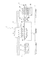
本実施形態のインクジェット記録装置1は筐体(図示せず)を備えており、その筐体内部には、図1に示すように左右方向に延在するガイドレール2が配設されている。ガイドレール2にはキャリッジ3が支持されており、キャリッジ3は図示しないキャリッジ駆動源31(図2参照)の動力によりガイドレール2上の所定の範囲を主走査方向Aに移動自在とされている。
The ink
キャリッジ3には、記録ヘッド4がその長手方向が副走査方向に平行となるように配置され、記録ヘッド4のノズル面41が記録媒体に対向するように配置されている。ノズル42の吐出口からは、イエロー(Y)、マゼンタ(M)、シアン(C)、ブラック(B)のいずれか一色の紫外線硬化性インクが記録媒体に対して吐出される。
In the
なお、本実施形態のインクジェット記録装置1はシリアル方式であるが、本発明においてはライン方式であってもよい。ここで、シリアル方式とは、記録ヘッドを搭載したキャリッジを主走査方向Aに往復させながら記録ヘッド吐出口より記録媒体にインクを吐出して画像を記録する方式をいい、ライン方式とは、複数の記録ヘッドを主走査方向Aに配列し、記録ヘッド直下を記録媒体が通過する際に記録媒体にインクを吐出して画像を記録する方式をいう。
The ink
キャリッジ3の左右両端には、紫外線を照射するための紫外線照射装置10が搭載されている。一方の紫外線照射装置10は、左端に位置した記録ヘッド4の更に左側に配置され、他方の紫外線照射装置10は、右端に位置した記録ヘッド4の更に右側に配置されている。紫外線照射装置10の内部には複数の紫外線光源が設けられており、紫外線光源は、紫外線を放射状に照射するものであり、高圧水銀ランプ、メタルハライドランプ、熱陰極管、冷陰極管、LED、無電極ランプ、エキシマランプ、低圧水銀ランプのうち、少なくともいずれか一つを適用することが好ましい。
キャリッジ3の走査範囲のうち中央部分は、記録媒体に記録を行う記録領域Yとされている。
The central part of the scanning range of the
記録領域Yには、キャリッジ3の下方に位置する平板状のプラテン5が設けられている。プラテン5は、記録ヘッド4により記録が行われる記録媒体を下から平坦状に支持するものである。筐体内部には、記録媒体Pを副走査方向に搬送するための記録媒体搬送機構9(図2参照)が設けられている。インクジェット記録装置1は、その筐体背面に記録媒体を筐体内部に送り込むためのスリット状の搬入口(図示せず)を備えるが、記録媒体はその搬入口から送り込まれると、筐体内部に配設された記録媒体搬送機構9によってプラテン5に支持され、その状態で筐体内部を副走査方向に通過し、筐体外部に搬出されるようになっている。
In the recording area Y, a
プラテン5の走査方向Aの左側は、画像記録を行っていないときに記録ヘッド4を待機させるホームポジション領域Xとされている。
The left side of the
ホームポジション領域Xには、遮光ユニット7が設けられている。遮光ユニット7には、非画像記録時に記録ヘッド4のノズル面41に光、特に紫外線が当たらないように遮光保護するための遮光キャップ71が記録ヘッド4に対応する数だけ設けられている。
また、遮光ユニット7には、遮光ユニット7を上下に移動させる図示しない遮光ユニット移動機構が備えられている。
In the home position area X, a
Further, the
プラテン5の走査方向Aの右側は、キャリッジ3に搭載された複数の記録ヘッド4をメンテナンスするためのメンテナンス領域Zとされており、ここにはメンテナンスユニット6が設けられている。
The right side in the scanning direction A of the
メンテナンスユニット6には、キャリッジ3がメンテナンス領域Zに移動した際に記録ヘッド4に対向する位置に、記録ヘッド4のノズル面41を覆うキャップ部材としての吸引キャップ61が、記録ヘッド4に対応する数だけ設けられている。吸引キャップ61の底面には、吸引キャップ61の内側に連通するインク連通管66が設けられている。このインク連通管66の中途には、吸引装置である吸引ポンプ64が設けられており、インク連通管66の下端には、吸引したインクを受ける廃インクタンク65が設けられている。
In the
また、メンテナンスユニット6には、吸引キャップ61に隣接して記録ヘッド4のノズル42に残留するインクを吸い取るインク吸収装置62が設けられている。インク吸収装置62は、長尺のシート状のインク吸収体8を巻回する送り出しロール軸81と巻き取りロール軸82とを備えており、図示しないロール軸駆動機構を駆動して巻き取りロール軸82を回転駆動させることにより、送り出しロール軸81から送り出されたインク吸収体8を巻き取りロール軸82に巻き取るようになっている。送り出しロール軸81と巻き取りロール軸82との間であってインク吸収体8の下面側には、インク吸収体8を下面側から約30℃〜60℃に加熱するヒータが配置されており、巻き取りロール軸82の一側には、例えば、LEDなどからなりインク吸収体8に対して紫外線を照射する紫外線照射部20が配設されている。
Further, the
また、メンテナンスユニット6には、メンテナンスユニット6を上下に移動させる図示しないメンテナンスユニット移動機構が備えられている。
The
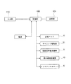
次に、図2を参照しつつ本実施の形態における制御部100について説明する。
Next, the
図2に示すように、インクジェット記録装置1は、各種処理を実行する制御部100を備えている。制御部100には、キャリッジ駆動源31、記録媒体搬送機構9、記録ヘッド4、紫外線照射装置10、メンテナンスユニット6が、それぞれインターフェース(図示せず)を介して接続されており、制御部100は上記各構成部をそれぞれ駆動制御するようになっている。
As shown in FIG. 2, the
制御部100は、キャリッジ3を主走査方向Aに往復駆動させるようにキャリッジ駆動源31を制御するようになっている。画像記録時には、記録媒体を副走査方向に搬送させるよう記録媒体搬送機構9を制御し、所定の画像記録情報に基づいて記録ヘッド4の吐出口から所要の色のインクを吐出させるように記録ヘッド4を制御する。そして、記録媒体上に着弾したインクに対して紫外線を照射させるように紫外線照射装置10を制御すると共に、紫外線照射装置10による紫外線照射時間をカウントする。また、制御部100は、メンテナンス間隔を選択し、選択したメンテナンス間隔に従ってメンテナンス動作を開始させるよう、メンテナンスユニット6を制御するようになっている。
The
また、インクジェット記録装置1は、制御、判断など各種処理用の各種プログラムや、各種データが格納されたROM及び各種処理における作業領域や各種処理によって生成されたデータを一時的に記憶するRAMによって構成される記憶部101を備えている。
The ink
記憶部101には、記録媒体の種類に対応づけられたメンテナンス間隔が予め記憶されている。このメンテナンス間隔は、各種の記録媒体における紫外線反射光の記録ヘッド4のノズル面41に到達する光エネルギー量によって決定される。
The
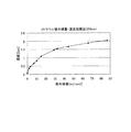
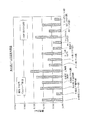
ここで、各種の記録媒体の紫外線反射光の光エネルギー量は、UVラベル(日油技研工業株式会社製:紫外線インジケータUVラベル 品種:S)によって把握することができる。図4に示すように、UVラベルは、照射される紫外線量が増加するにつれて、UVラベルの色の濃度が高くなるという特性を有する。このUVラベルを記録ヘッド4のノズル面41に貼り付け、各種の記録媒体について、一定時間動作後におけるUVラベルの濃度変化を測定する。
Here, the amount of light energy of ultraviolet reflected light of various recording media can be grasped by a UV label (manufactured by NOF Corporation: UV indicator UV label type: S). As shown in FIG. 4, the UV label has a characteristic that the density of the color of the UV label increases as the amount of irradiated ultraviolet light increases. This UV label is affixed to the
図5は、記録媒体ごとに一定時間におけるUVラベルの濃度変化を測定した結果を示すものである。一般に、PETフィルムなど表面粗さが小さい記録媒体においては紫外線が正反射しやすく、上質紙、アルミホイル、コート紙など表面に凸凹がある記録媒体においては紫外線が乱反射しやすい。また、紫外線が記録媒体の表面において乱反射する場合は、正反射する場合に比べると、紫外線反射光が印字面以外の部分(記録ヘッド4のノズル面41など)に到達しやすくなる。したがって図5に示すとおり、PETフィルムの場合の濃度変化は小さく、上質紙、アルミホイル、コート紙などの場合の濃度変化は大きくなっている。
FIG. 5 shows the result of measuring the change in the density of the UV label for a certain time for each recording medium. In general, a recording medium having a small surface roughness such as a PET film is likely to reflect ultraviolet rays regularly, and a recording medium such as high-quality paper, aluminum foil, or coated paper is likely to be irregularly reflected by ultraviolet rays. Further, when the ultraviolet rays are irregularly reflected on the surface of the recording medium, the ultraviolet reflected light is likely to reach a portion other than the print surface (such as the
本実施形態においては、これらの結果に基づき、UVラベルの濃度が0.25Den、すなわち光量換算すると光エネルギー量が1mJ/cm2に達するまでの時間を、各種の記録媒体のメンテナンス間隔として記憶部に記憶している。なお、光エネルギー量が1mJ/cm2以上となる前にメンテナンス動作に移行すれば、ノズル面41のインクが硬化し始める前にメンテナンスを行い、ノズル面41のインクを除去することができる。
In the present embodiment, based on these results, the concentration of the UV label is 0.25 Den, that is, the time until the amount of light energy reaches 1 mJ / cm 2 in terms of the amount of light is stored as a maintenance interval of various recording media. I remember it. If the maintenance operation is started before the amount of light energy becomes 1 mJ / cm 2 or more, the maintenance can be performed before the ink on the
ここで、記録ヘッド4のノズル面41に到達する紫外線反射光の光エネルギー量が多い記録媒体ほど、ノズル面41のインク硬化をおこしやすいが、かかる記録媒体については一定時間におけるUVラベルの濃度が高く、光エネルギー量が1mJ/cm2に達するまでの時間は短くなる。反対に、紫外線反射光の光エネルギー量が少ない記録媒体については、一定時間におけるUVラベルの濃度が低く、光エネルギー量が1mJ/cm2以上に達するまでの時間は長くなる。
Here, a recording medium having a larger amount of light energy of the reflected ultraviolet light reaching the
そこで、本実施形態においては、記録ヘッド4のノズル面41に到達する紫外線反射光の光エネルギー量が多い記録媒体については短いメンテナンス間隔が、光エネルギー量が少ない記録媒体については長いメンテナンス間隔が対応づけられて記憶部101に記憶されている。
Therefore, in the present embodiment, a short maintenance interval corresponds to a recording medium with a large amount of light energy of ultraviolet reflected light reaching the
また、インクジェット記録装置1は、操作入力やデータや情報の入力を行うキーボードや操作パネルなどを有する入力部110を備えている。入力部110は、ユーザーによって記録媒体の種類を入力することができるように構成され、本実施形態においては、紫外線反射光の光エネルギー量の値が近似する記録媒体をカテゴリー化し、操作パネル上のボタンによって選択できるようにされている。またこの他に、記録媒体名をキーボードによって入力させてからいずれのカテゴリーに当てはまるか制御部100に判別させ、その上でメンテナンス間隔を選択できるようにすることもできる。
In addition, the
ここで、本実施形態に用いられるインクについて説明する。インクを硬化させる際、インクに含まれる重合性化合物を重合反応させるが、本実施形態におけるインクは重合性化合物として活性化エネルギー線硬化性化合物を含んでおり、重合反応を開始させる活性化エネルギーとして紫外線を使用した紫外線硬化性インクである。 Here, the ink used in this embodiment will be described. When the ink is cured, the polymerizable compound contained in the ink undergoes a polymerization reaction, but the ink in the present embodiment includes an activation energy ray-curable compound as the polymerizable compound, and serves as an activation energy for initiating the polymerization reaction. It is an ultraviolet curable ink using ultraviolet rays.
紫外線硬化性インクには、重合性化合物として、ラジカル重合性化合物を含むラジカル硬化性インクとカチオン重合性化合物を含むカチオン硬化性インクとに大別されるが、どちらのインクも本実施の形態に用いられるインクとして適用可能であり、ラジカル硬化性インクとカチオン硬化性インクとを複合させたハイブリッド型インクを本実施の形態に用いられるインクとして適用してもよい。 The ultraviolet curable ink is roughly classified into a radical curable ink containing a radical polymerizable compound and a cation curable ink containing a cationic polymerizable compound as a polymerizable compound. It can be applied as an ink to be used, and a hybrid ink in which a radical curable ink and a cationic curable ink are combined may be applied as an ink used in this embodiment.
しかしながら、酸素による重合反応の阻害が少ない又は無いカチオン硬化性インクのほうが機能性・汎用性に優れるため、本実施の形態では、特に、カチオン硬化性インクを用いている。本実施の形態に用いられるカチオン硬化性インクは、具体的に、少なくともオキセタン化合物、エポキシ化合物、ビニルエーテル化合物などのカチオン重合性化合物と、光カチオン開始剤と、色材とを含む混合物であり、上記の紫外線の被照射により硬化する性質を具備するものである。 However, a cationic curable ink that uses less or no inhibition of the polymerization reaction due to oxygen is superior in functionality and versatility. Therefore, in this embodiment, a cationic curable ink is used. The cation curable ink used in the present embodiment is specifically a mixture containing at least a cation polymerizable compound such as an oxetane compound, an epoxy compound, and a vinyl ether compound, a photo cation initiator, and a coloring material. It has the property of being cured by irradiation with ultraviolet rays.
また、本実施形態におけるインクの粘度は、25℃において10〜50mPa・sで表面張力は20〜40mN/mであり、いわゆる粘性が高く、濡れ性が悪いインクである。 In addition, the viscosity of the ink in the present embodiment is 10 to 50 mPa · s at 25 ° C. and the surface tension is 20 to 40 mN / m, so-called high viscosity and poor wettability.
また、本実施の形態に用いられる記録媒体としては、通常のインクジェット記録装置1に適用される普通紙、再生紙、光沢紙などの各種紙、各種布地、各種不織布、樹脂、金属、ガラスなどの材質からなるものが適用可能である。また、記録媒体の形態としては、ロール状、カットシート状、板状などが適用可能である。
The recording medium used in the present embodiment includes various papers such as plain paper, recycled paper, and glossy paper, various fabrics, various non-woven fabrics, resin, metal, glass, and the like that are applied to the normal
さらに、本実施の形態に用いられる記録媒体として、樹脂によって表面を被覆した各種紙、顔料を含むフィルム、発泡フィルムなどの不透明な公知の記録媒体を適用することも可能である。 Further, as the recording medium used in the present embodiment, it is also possible to apply known opaque recording media such as various papers whose surfaces are coated with a resin, a film containing a pigment, and a foam film.
次に、以上のように構成されたインクジェット記録装置1の動作について、図3を参照して説明する。
Next, the operation of the
まず、本実施の形態に係るインクジェット記録装置1は、電源をオン状態とすると、紫外線照射装置10の紫外線光源が点灯状態となる。また、本実施の形態の紫外線光源は、電源をオフ状態とするまで常に点灯状態を保つようになっている。
First, in the
制御部100に所定の画像記録情報が入力されると、インクジェット記録装置1は画像記録を開始する。画像記録時には、制御部100は、記録ヘッド4及び紫外線照射装置10を搭載したキャリッジ3を駆動させることにより記録ヘッド4及び紫外線照射装置10を主走査方向Aに往復駆動させるとともに、記録媒体搬送機構9により記録媒体を副走査方向に搬送させながら、所定の画像記録情報に基づいて記録ヘッド4の吐出口から所要の色のインクを吐出させる。そして、記録ヘッド4の吐出口から吐出されたインクが記録媒体の上に着弾し、この着弾したインクに対して紫外線照射装置10から紫外線照射が行われることによりインクが硬化され、記録媒体に画像が記録される。
When predetermined image recording information is input to the
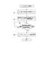
次に、インクジェット記録装置1において行われるメンテナンス処理について、図3のフローチャートを用いて説明する。
Next, the maintenance process performed in the
まず、ユーザーによって、入力部110に記録媒体の種類が入力される(ステップS1)。
First, the type of the recording medium is input to the
入力部110に記録媒体の種類が入力されると、制御部100は、キャリッジ3が記録領域Y又はホームポジション領域Xにある状態で、入力された記録媒体の種類に対応するメンテナンス間隔を記憶部101から選択する(ステップS2)。
すなわち、制御部100は、紫外線反射光のエネルギー量が多いカテゴリーの記録媒体については短いメンテナンス間隔を、紫外線反射光のエネルギー量が少ないカテゴリーの記録媒体については長いメンテナンス間隔を選択する。
また、予め記憶部に記憶されていない記録媒体名がキーボードなどにより入力部110に入力された場合には、制御部100は紫外線反射光の光エネルギー量が最も多い記録媒体のカテゴリーに対応する最も短いメンテナンス間隔を選択する。
When the type of the recording medium is input to the
That is, the
In addition, when a recording medium name not previously stored in the storage unit is input to the
制御部100は、紫外線照射装置10の光源による紫外線照射の累積時間をカウントしており、この累積時間が選択されたメンテナンス間隔の時間を経過したか否かを判断する(ステップS3)。そして、制御部100は、紫外線照射時間が選択されたメンテナンス間隔の時間を経過したと判断すると、記録ヘッド4及び紫外線照射装置10を備えたキャリッジ3をメンテナンス領域Zへ移動させる。
The
記録ヘッド4がメンテナンス領域Zに到達すると、制御部100はメンテナンスユニット6にメンテナンス動作を開始させる(ステップS4)。
When the
記録ヘッド4が吸引キャップ61の位置まで移動すると、制御部100はメンテナンスユニット6を上昇させる。これにより、メンテナンスユニット6に設けられた吸引キャップ61が記録ヘッド4のノズル面41を覆って密閉する。さらに、制御部100が吸引ポンプ64を作動させて吸引キャップ61の内部に負圧をかけ、ノズル42内のインクを吸引する。吸収されたインクはインク連通管66を通じて廃インクタンク65に送られて蓄えられる。吸引終了後、制御部100は、メンテナンスユニット6を下降させ、ノズル42のノズル面41から吸引キャップ61を離間させる。
When the
次に、記録ヘッド4がインク吸収装置62の位置まで移動すると、制御部100はメンテナンスユニット6を上昇させる。これにより、送り出しロール軸81と巻き取りロール軸82に掛け渡されたインク吸収体8がノズル面41に当接し、ノズル面41に付着したインクを吸収する。その後、制御部100がロール軸駆動機構を駆動して巻き取りロール軸82を回転駆動させることにより、送り出しロール軸81から送り出されたインク吸収体8を巻き取りロール軸82に巻き取る。この際、制御部100は紫外線照射部20を駆動してインク吸収体8に紫外線を照射し、インク吸収体8に吸収されたインクを硬化させる。最後に、制御部100はノズル42からインク吸収体8にインクを空吐出させる。その後、制御部100はメンテナンスユニット6を下降させ、ノズル面41からインク吸収体8を離間させる。
Next, when the
以上により、記録ヘッド4のメンテナンス処理は終了し、制御部100はキャリッジ3をホームポジション領域Xに移動させる。
Thus, the maintenance process of the
メンテナンス処理が終了すると、制御部100は再び紫外線照射時間をカウントし、紫外線照射時間が選択されたメンテナンス間隔の時間を超えると、上記と同様にメンテナンス動作を開始させる。
When the maintenance process is completed, the
また、ユーザーにより入力部110において異なる種類の記録媒体が入力されると、それに対応するメンテナンス間隔が記憶部101から選択され、新しく選択されたメンテナンス間隔に従って、上記と同様にメンテナンスユニット6が制御される。
When a different type of recording medium is input by the user at the
以上述べたように、本発明によれば、予め記録媒体の種類に応じたメンテナンス間隔を記憶させておくので、ユーザーは記録媒体の種類を入力するのみで適切なメンテナンス間隔が選択される。また、メンテナンス間隔は紫外線反射光が記録ヘッドのノズル面41に到達する光エネルギー量によって決定されているので、光エネルギー量に応じた最適なメンテナンス間隔を選択させることができる。すなわち、光エネルギー量の多い記録媒体、つまりノズル面41のインクを硬化させやすい記録媒体については短いメンテナンス間隔を選択させることで、ノズル面41のインク硬化を効果的に防止することができる。また、光エネルギー量が少ない記録媒体、つまりノズル面41のインクを硬化させにくい記録媒体については比較的長いメンテナンス間隔を選択させることで、無駄なインクの消費を最小限に止めると共に、インクジェット記憶装置の生産性を高めることができる。このように、記録媒体の種類によってメンテナンス間隔を変更することで、インク硬化を防止しつつ無駄なインクの消費を抑えることのできる、最適なメンテナンスを行うことが可能となる。特にカチオン硬化性インクには光エネルギーを蓄積させるという特徴があることから、微量な光量でも時間により蓄積され、最終的には硬化してしまい、また、一度硬化したインクはメンテナンスによって除去することはできない。しかし、このように適切なメンテナンス間隔を選択させることによって、ノズル面41のインクが硬化する前にメンテナンスを行い、インク硬化を未然に防止することができる。
As described above, according to the present invention, since the maintenance interval corresponding to the type of the recording medium is stored in advance, the user can select an appropriate maintenance interval only by inputting the type of the recording medium. Further, since the maintenance interval is determined by the amount of light energy that the ultraviolet reflected light reaches the
特に紫外線硬化性インクは、記録媒体の種類を選ばず印字することができるが、このように印字される記録媒体の種類に応じてメンテナンス間隔を選択し、ノズル面41のインク硬化を最適に防止することで、こうしたあらゆる種類の記録媒体において高画質を得ることが可能となる。
In particular, UV curable ink can be printed regardless of the type of recording medium, but the maintenance interval is selected according to the type of recording medium printed in this way, and the ink curing of the
1 インクジェット記録装置
2 ガイドレール
3 キャリッジ
31 キャリッジ駆動機構
4 記録ヘッド
5 プラテン
6 メンテナンスユニット
61 吸引キャップ
62 インク吸引装置
7 遮光ユニット
8 インク吸収体
81 第1のロール軸
82 第2のロール軸
83 ヒータ
9 記録媒体搬送機構
10 紫外線照射装置
20 紫外線照射部
100 制御部
101 記憶部
110 入力部
A 走査方向
X ホームポジション領域
Y 記録領域
Z メンテナンス領域
DESCRIPTION OF
Claims (10)
前記記録ヘッドのメンテナンスを行うメンテナンスユニットと、
記録媒体の種類を入力する入力部と、
前記記録媒体の種類とメンテナンス間隔とを対応づけて記憶する記憶部と、
前記入力部に入力された記録媒体の種類によってメンテナンス間隔を選択し、このメンテナンス間隔に従ってメンテナンス動作をさせるように前記メンテナンスユニットを制御する制御部と、
を備えることを特徴とするインクジェット記録装置。 A carriage having a recording head for discharging the ultraviolet curable ink toward the recording medium, and an ultraviolet irradiation device for irradiating the ink landed on the recording medium with ultraviolet rays to cure the ink;
A maintenance unit for performing maintenance of the recording head;
An input unit for inputting the type of recording medium;
A storage unit for storing the type of the recording medium and the maintenance interval in association with each other;
A control unit that selects a maintenance interval according to the type of the recording medium input to the input unit and controls the maintenance unit to perform a maintenance operation according to the maintenance interval;
An ink jet recording apparatus comprising:
ある前記インクを使用することを特徴とする請求項1〜9のいずれか一項に記載のイン
クジェット記録装置。 The ink jet recording apparatus according to claim 1, wherein the ink having a viscosity of 10 to 50 mPa · s at 25 ° C. and a surface tension of 20 to 40 mN / m is used.
Priority Applications (2)
| Application Number | Priority Date | Filing Date | Title |
|---|---|---|---|
| JP2004112772A JP4529522B2 (en) | 2004-04-07 | 2004-04-07 | Inkjet recording device |
| US11/097,290 US7396103B2 (en) | 2004-04-07 | 2005-04-04 | Inkjet recording apparatus and method for maintenance of recording head |
Applications Claiming Priority (1)
| Application Number | Priority Date | Filing Date | Title |
|---|---|---|---|
| JP2004112772A JP4529522B2 (en) | 2004-04-07 | 2004-04-07 | Inkjet recording device |
Publications (2)
| Publication Number | Publication Date |
|---|---|
| JP2005297230A true JP2005297230A (en) | 2005-10-27 |
| JP4529522B2 JP4529522B2 (en) | 2010-08-25 |
Family
ID=35060129
Family Applications (1)
| Application Number | Title | Priority Date | Filing Date |
|---|---|---|---|
| JP2004112772A Expired - Fee Related JP4529522B2 (en) | 2004-04-07 | 2004-04-07 | Inkjet recording device |
Country Status (2)
| Country | Link |
|---|---|
| US (1) | US7396103B2 (en) |
| JP (1) | JP4529522B2 (en) |
Cited By (6)
| Publication number | Priority date | Publication date | Assignee | Title |
|---|---|---|---|---|
| JP2009517238A (en) * | 2005-11-16 | 2009-04-30 | ガーバー サイエンティフィック インターナショナル インコーポレイテッド | Photocuring of cationic inks on acidic substrates |
| CN102218911A (en) * | 2010-03-30 | 2011-10-19 | 精工爱普生株式会社 | Image forming method and ink jet recording device |
| JP2013237005A (en) * | 2012-05-15 | 2013-11-28 | Sumitomo Heavy Ind Ltd | Thin film forming device and adjusting method for thin film forming device |
| JP2016000523A (en) * | 2014-05-22 | 2016-01-07 | 大日本印刷株式会社 | Laminate manufacturing method and adhesive sheet used therefor |
| JP2018187854A (en) * | 2017-05-09 | 2018-11-29 | セイコーエプソン株式会社 | Droplet discharge device |
| JP2023004093A (en) * | 2021-06-25 | 2023-01-17 | ローランドディー.ジー.株式会社 | printer |
Families Citing this family (5)
| Publication number | Priority date | Publication date | Assignee | Title |
|---|---|---|---|---|
| US20070251403A1 (en) * | 2006-04-27 | 2007-11-01 | St John Kenneth | Printing and curing apparatus system and method |
| JP5991164B2 (en) * | 2012-11-21 | 2016-09-14 | セイコーエプソン株式会社 | RECORDING DEVICE, RECORDING DEVICE MAINTENANCE METHOD, AND RECORDING METHOD |
| US10180248B2 (en) | 2015-09-02 | 2019-01-15 | ProPhotonix Limited | LED lamp with sensing capabilities |
| JP6642129B2 (en) * | 2016-03-08 | 2020-02-05 | セイコーエプソン株式会社 | Liquid ejection device |
| JP7097844B2 (en) | 2019-03-29 | 2022-07-08 | キヤノン株式会社 | Recording device |
Citations (3)
| Publication number | Priority date | Publication date | Assignee | Title |
|---|---|---|---|---|
| JP2003039693A (en) * | 2001-07-31 | 2003-02-13 | Canon Inc | Ink jet recording apparatus and ink jet recording method |
| JP2003326691A (en) * | 2002-05-09 | 2003-11-19 | Konica Minolta Holdings Inc | Image recording method, energy line hardening ink, and image recorder |
| JP2004090245A (en) * | 2002-08-29 | 2004-03-25 | Canon Inc | Inkjet recording device |
Family Cites Families (3)
| Publication number | Priority date | Publication date | Assignee | Title |
|---|---|---|---|---|
| US6179403B1 (en) * | 1999-07-09 | 2001-01-30 | Xerox Corporation | Document dependent maintenance procedure for ink jet printer |
| US7159963B2 (en) * | 2003-04-24 | 2007-01-09 | Konica Minolta Medical & Graphic, Inc. | Image recording apparatus with wipe unit and nozzle maintenance unit |
| JP2005144679A (en) * | 2003-11-11 | 2005-06-09 | Roland Dg Corp | Inkjet printer |
-
2004
- 2004-04-07 JP JP2004112772A patent/JP4529522B2/en not_active Expired - Fee Related
-
2005
- 2005-04-04 US US11/097,290 patent/US7396103B2/en active Active
Patent Citations (3)
| Publication number | Priority date | Publication date | Assignee | Title |
|---|---|---|---|---|
| JP2003039693A (en) * | 2001-07-31 | 2003-02-13 | Canon Inc | Ink jet recording apparatus and ink jet recording method |
| JP2003326691A (en) * | 2002-05-09 | 2003-11-19 | Konica Minolta Holdings Inc | Image recording method, energy line hardening ink, and image recorder |
| JP2004090245A (en) * | 2002-08-29 | 2004-03-25 | Canon Inc | Inkjet recording device |
Cited By (7)
| Publication number | Priority date | Publication date | Assignee | Title |
|---|---|---|---|---|
| JP2009517238A (en) * | 2005-11-16 | 2009-04-30 | ガーバー サイエンティフィック インターナショナル インコーポレイテッド | Photocuring of cationic inks on acidic substrates |
| CN102218911A (en) * | 2010-03-30 | 2011-10-19 | 精工爱普生株式会社 | Image forming method and ink jet recording device |
| JP2013237005A (en) * | 2012-05-15 | 2013-11-28 | Sumitomo Heavy Ind Ltd | Thin film forming device and adjusting method for thin film forming device |
| JP2016000523A (en) * | 2014-05-22 | 2016-01-07 | 大日本印刷株式会社 | Laminate manufacturing method and adhesive sheet used therefor |
| JP2018187854A (en) * | 2017-05-09 | 2018-11-29 | セイコーエプソン株式会社 | Droplet discharge device |
| JP2023004093A (en) * | 2021-06-25 | 2023-01-17 | ローランドディー.ジー.株式会社 | printer |
| JP7629810B2 (en) | 2021-06-25 | 2025-02-14 | ローランドディー.ジー.株式会社 | Printer |
Also Published As
| Publication number | Publication date |
|---|---|
| US20050225620A1 (en) | 2005-10-13 |
| US7396103B2 (en) | 2008-07-08 |
| JP4529522B2 (en) | 2010-08-25 |
Similar Documents
| Publication | Publication Date | Title |
|---|---|---|
| JP4529522B2 (en) | Inkjet recording device | |
| JP2009226692A (en) | Inkjet printer | |
| JP2008073916A (en) | Inkjet recording device | |
| JP2004203025A (en) | Image recording apparatus | |
| JP2004330773A (en) | Ink-jet printer | |
| JP5028862B2 (en) | Inkjet recording device | |
| JP2005212351A (en) | Inkjet printer | |
| JP2005262553A (en) | Image recording apparatus | |
| JP2006110974A (en) | Inkjet printer | |
| JP2004358953A (en) | Inkjet recording device | |
| JP2009083208A (en) | Inkjet recording device | |
| JP2007118414A (en) | Inkjet recording device | |
| JP2006068937A (en) | Inkjet printer | |
| JP2005104116A (en) | Inkjet printer | |
| JP2005205631A (en) | Ink-jet printer | |
| JP2004230640A (en) | Ink-jet printer | |
| JP4419478B2 (en) | Inkjet printer | |
| JP4806955B2 (en) | Inkjet printer | |
| WO2006013726A1 (en) | Ink jet recorder | |
| JP2004195852A (en) | Ink-jet printer | |
| JP2004155047A (en) | Ink jet printer | |
| JP2010173328A (en) | Inkjet recording apparatus | |
| JP2008105268A (en) | Inkjet image forming apparatus for photocurable ink and inkjet image forming method | |
| JP4356325B2 (en) | Inkjet recording device | |
| JP2006150633A (en) | Inkjet recorder |
Legal Events
| Date | Code | Title | Description |
|---|---|---|---|
| A621 | Written request for application examination |
Free format text: JAPANESE INTERMEDIATE CODE: A621 Effective date: 20070308 |
|
| A977 | Report on retrieval |
Free format text: JAPANESE INTERMEDIATE CODE: A971007 Effective date: 20100222 |
|
| A131 | Notification of reasons for refusal |
Free format text: JAPANESE INTERMEDIATE CODE: A131 Effective date: 20100309 |
|
| A521 | Request for written amendment filed |
Free format text: JAPANESE INTERMEDIATE CODE: A523 Effective date: 20100408 |
|
| TRDD | Decision of grant or rejection written | ||
| A01 | Written decision to grant a patent or to grant a registration (utility model) |
Free format text: JAPANESE INTERMEDIATE CODE: A01 Effective date: 20100518 |
|
| A01 | Written decision to grant a patent or to grant a registration (utility model) |
Free format text: JAPANESE INTERMEDIATE CODE: A01 |
|
| A61 | First payment of annual fees (during grant procedure) |
Free format text: JAPANESE INTERMEDIATE CODE: A61 Effective date: 20100531 |
|
| R150 | Certificate of patent or registration of utility model |
Free format text: JAPANESE INTERMEDIATE CODE: R150 Ref document number: 4529522 Country of ref document: JP Free format text: JAPANESE INTERMEDIATE CODE: R150 |
|
| FPAY | Renewal fee payment (event date is renewal date of database) |
Free format text: PAYMENT UNTIL: 20130618 Year of fee payment: 3 |
|
| S111 | Request for change of ownership or part of ownership |
Free format text: JAPANESE INTERMEDIATE CODE: R313111 |
|
| R350 | Written notification of registration of transfer |
Free format text: JAPANESE INTERMEDIATE CODE: R350 |
|
| LAPS | Cancellation because of no payment of annual fees |