JP4356290B2 - Game machine - Google Patents
Game machine Download PDFInfo
- Publication number
- JP4356290B2 JP4356290B2 JP2002221113A JP2002221113A JP4356290B2 JP 4356290 B2 JP4356290 B2 JP 4356290B2 JP 2002221113 A JP2002221113 A JP 2002221113A JP 2002221113 A JP2002221113 A JP 2002221113A JP 4356290 B2 JP4356290 B2 JP 4356290B2
- Authority
- JP
- Japan
- Prior art keywords
- game ball
- flow
- game
- center frame
- frame
- Prior art date
- Legal status (The legal status is an assumption and is not a legal conclusion. Google has not performed a legal analysis and makes no representation as to the accuracy of the status listed.)
- Expired - Fee Related
Links
Images


Description
【0001】
【発明の属する技術分野】
本発明は、パチンコ機等の遊技機に関するものである。
【0002】
【従来の技術】
従来、遊技機の一種として、遊技盤面上における遊技球の挙動に起因して種々の遊技状態が導出されるパチンコ機が知られている。このようなパチンコ機で遊技を行う遊技者は、所定の遊技状態の導出を期待し、遊技盤面上の遊技球の挙動に期待感を持って注目する。
【0003】
そして、遊技者に遊技球の挙動を視認させ興趣の向上を図るため、可変表示装置を囲むセンターフレームの下部などに、遊技球が転動可能なステージを設けたパチンコ機が見受けられる。このようなセンターフレームには、その上部からステージへ遊技球を導くための遊技球流路が設けられることがあった。
【0004】
さらに、遊技球流路を通過して流下する遊技球の速度を抑えるため、あるいは、遊技球の動きに変化を持たせるため、遊技球流路内部に、遊技球の流下状態を変更する流下状態変更部を備えることが考えられる。
【0005】
【発明が解決しようとする課題】
この流下状態変更部は、繰り返される遊技球の接触により、埃などが付着して汚れることが多い。流下状態変更部に汚れが付着すれば、この部分に遊技球がつまったりする可能性も高くなり、遊技の興趣を損なうことにもなりかねない。
【0006】
しかしながら、この流下状態変更部は、その保守が困難であった。
【0007】
本発明は、このような遊技球流路に配置される流下状態変更部に対する保守が容易な遊技機を提供することを目的とする。
【0008】
【課題を解決するための手段及び発明の効果】
上記の目的を達成するために、本発明においては、
遊技盤に対し設けられ、識別情報を変動表示可能な可変表示装置の周囲を囲むセンターフレームを備え、
該センターフレームは、
当該センターフレームの下部に設けられ、自身の上面を遊技球が転動可能となっているステージ部と、
当該センターフレームの側部に設けられ、入口部から流入した遊技球を出口部を介し前記ステージ部へと案内可能になっている遊技球流路とを具備する遊技機であって、
前記遊技球流路内部に、前記遊技球の流下状態を変更する流下状態変更部を有しており、
さらに、前記センターフレームには、前記遊技球流路の入口部・出口部とは別に、前記流下状態変更部よりも遊技球流下方向の上流側に開口部を設け、当該開口部から、前記流下状態変更部の少なくとも一部を視認可能とし、
前記遊技球流路の入口部は、前記センターフレームの前記遊技盤への取付状態における当該遊技盤の前面よりも前側において前記センターフレームの上部又は側部に設けられており、
前記開口部は、前記センターフレームの前記遊技盤への取付状態における当該遊技盤の前面よりも後側において前記センターフレームに設けられていることを特徴とする。
また、前記流下状態変更部は、前記遊技球流路を構成する後側パネルから前面側へ突出し、前記遊技球の流下速度及び流れ方向の変更を担うリブであることとしてもよい。
また、前記遊技機はパチンコ機であることとしてもよい。
本発明によれば、遊技球流路に配置される流下状態変更部に対する保守が容易となる。
【0009】
【発明の実施の形態】
手段1.遊技盤に、入口部から流入した遊技球を出口部を介し遊技領域の所定部分へと案内可能となっている遊技球流路を備えた遊技機であって、
前記遊技球流路内部に、前記遊技球の流下状態を変更する流下状態変更部を有しており、
さらに、前記遊技球流路の入口部・出口部とは別に、前記流下状態変更部の保守を行うための開口部を設けたことを特徴とする遊技機。
【0010】
手段1によれば、遊技球流路の入口部・出口部とは別に、遊技球流路内の流下状態変更部の保守を行うための開口部を設けたため、遊技球流路内部に流下状態変更部が配置されていても、開口部を介して流下状態変更部に対する保守を容易に行うことができる。
【0011】
なお、流下状態の変更には、遊技球の流下速度の変更や、流路の変更などが含まれる(以下の手段でも同じ)。また、上述した遊技球流路は、略直線状の流路となっていることも考えられるし、湾曲した流路となっていることも考えられる(以下の手段でも同じ)。特に遊技球流路が湾曲している場合においては、入口部・出口部を介した保守が困難となるため、大きな効果を奏する。
【0012】
手段2.遊技盤の遊技領域に設けられる枠体を備え、該枠体は、当該枠体の下部に取付けられ、自身の上面を遊技球が転動可能となっているステージ部と、当該枠体の側部に設けられ、入口部から流入した遊技球を出口部を介し前記ステージ部へと案内可能になっている遊技球流路とを具備してなる遊技機であって、
前記遊技球流路内部に、前記遊技球の流下状態を変更する流下状態変更部を有しており、
さらに、前記遊技球流路の入口部・出口部とは別に、前記流下状態変更部の保守を行うための開口部を前記枠体に設けたことを特徴とする遊技機。
【0013】
手段2では、枠体を備えており、この枠体が、遊技球の転動を許容するステージ部、及び、入口部から流入した遊技球をステージ部へ導く遊技球流路を具備してなる。
【0014】
ここで特に、遊技球流路の入口部・出口部とは別に、遊技球流路内の流下状態変更部の保守を行うための開口部を枠体に設けたため、遊技球流路内部に流下状態変更部が配置されていても、開口部を介して流下状態変更部に対する保守を容易に行うことができる。特に遊技球流路が湾曲している場合においては、入口部・出口部を介した保守が困難となるため、大きな効果を奏する。
【0015】
なお、「前記入口部は、前記枠体の上部又は側部に設けられていること」としてもよい。
【0016】
手段3.手段2において、前記枠体は、識別情報を変動表示可能な可変表示装置の周囲を囲むセンターフレームによって構成されていることを特徴とする遊技機。
【0017】
手段4.手段2又は3において、前記開口部は、前記枠体を前記遊技領域に取り付けた状態で、前記流下状態変更部の保守が可能となるよう設けられていることを特徴とする遊技機。
【0018】
手段4によれば、遊技領域に設けられる枠体を、当該遊技領域から取り外すことなく、開口部を介した保守が可能となるため、流下状態変更部に対する保守が容易になる。
【0019】
手段5.手段1乃至4のいずれかにおいて、前記開口部は、前記流下状態変更部の清掃を行うための清掃孔であることを特徴とする遊技機。
【0020】
手段5によれば、開口部が流下状態変更部の清掃を行うための清掃孔となっているため、例えば綿棒などを用いることにより、開口部を介して、流下状態変更部の清掃を行うことができる。
【0021】
その結果、繰り返される遊技球の接触により、埃などが付着して、流下状態変更部が汚れることを適切に防止できる。これによって、遊技球がつまったりする可能性を低くすることができ、遊技の興趣を損なうことを防止できる。
【0022】
手段6.手段1乃至5のいずれかにおいて、前記開口部は、前記流下状態変更部の点検を行うための点検孔であることを特徴とする遊技機。
【0023】
手段6によれば、開口部が流下状態変更部の点検を行うための点検孔となっているため、湾曲した遊技球流路内部に流下状態変更部が配置されていても、開口部を介して、流下状態変更部に対する点検を容易に行うことができる。
【0024】
手段7.手段6において、前記点検孔は、前記流下状態変更部が汚れているか否かを点検するためのものであることを特徴とする遊技機。
【0025】
手段7によれば、点検孔を介して流下状態変更部が汚れているか否かの点検を行うことができ、適切なタイミングで清掃などを行うことができる。
【0026】
手段8.手段6又は7において、前記点検孔は、前記流下状態変更部が破損しているか否かを点検するためのものであることを特徴とする遊技機。
【0027】
流下状態変更部は、繰り返される遊技球の接触により、破損することが考えられる。この点、手段8によれば、点検孔を介して流下状態変更部が破損しているか否かの点検を行うことができ、破損した状態にあることを速やかに発見することができる。
【0028】
手段9.手段1乃至8のいずれかにおいて、前記開口部は、前記流下状態変更部に留まった遊技球を再び流下させるための流下強制孔であることを特徴とする遊技機。
【0029】
手段9によれば、開口部が流下状態変更部に留まった遊技球を再び流下させるための流下強制孔となっているため、湾曲した遊技球流路内部の流下状態変更部に遊技球がつまった場合でも、開口部を介して、その遊技球を再び流下させることができる。例えば、棒状の部材を差し込んで、遊技球を遊技球流路の出口部より排出するという具合である。つまり、遊技の途中に発生する不具合にも迅速に対応することができ、遊技の興趣が損なわれることを防止できる。
【0030】
手段10.手段1乃至9のいずれかにおいて、前記開口部は、前記遊技球流路における前記遊技球の前記流下状態変更部へ向かう流下方向の上流側に設けられていることを特徴とする遊技機。
【0031】
特に流下状態変更部の破損は、球勢によって大きな衝撃がかかる部分に生じやすい。この点、手段10によれば、遊技球の流下方向の上流側に開口部が設けられているため、破損しやすい部分の点検が容易に行える。その結果、適切な点検が可能となる。
【0032】
手段11.手段1乃至10のいずれかにおいて、前記開口部は、当該開口部を通して前記流下状態変更部の少なくとも一部を視認可能に設けられていることを特徴とする遊技機。
【0033】
上述したような開口部を介した点検は、例えば、綿棒などの棒状部材を用いて行うことが考えられる。これに対し、手段11によれば、流下状態変更部の少なくとも一部が視認できるように開口部が設けられているため、作業者は、自分の目で、流下状態変更部の点検を行うことができる。これによって、流下状態変更部の清掃や点検を適切に行うことができる。
【0034】
手段12.手段2乃至10のいずれかにおいて、前記開口部は、前記枠体を前記遊技領域に取り付けた状態で、当該開口部を通して前記流下状態変更部の少なくとも一部を視認可能に設けられていることを特徴とする遊技機。
【0035】
手段12によれば、手段11の効果に加え、遊技領域に設けられる枠体を、当該遊技領域から取り外すことなく、流下状態変更部が視認可能になっているため、流下状態変更部に対する保守が容易になる。
【0036】
手段13.手段1乃至12のいずれかにおいて、前記遊技機はパチンコ機であること。中でも、パチンコ機の基本構成としては、「操作ハンドルを備えておりそのハンドル操作に応じて遊技球を遊技盤面上に発射させ、遊技球が遊技盤を流下し、遊技盤に配設された特定の入球手段に入球することに基づいて、所定条件が成立した場合には特別遊技価値が付与されるもの」が挙げられる。
【0037】
以下、パチンコ遊技機(以下、単に「パチンコ機」という)の一実施の形態を、図面に基づいて詳細に説明する。
【0038】
図1に示すように、パチンコ機1は、外枠2と、該外枠2の前部に設けられ外枠2の一側部にて開閉可能に支持された前面枠3とを備えている。
【0039】
前面枠3の前面側にはガラス扉枠4が開閉自在に設けられている。前面枠3の後側(ガラス扉枠4の奥、外枠2の内側)には、遊技盤5が着脱可能に装着されている。
【0040】
ガラス扉枠4の下方には、遊技球Bを貯留するための球受皿としての上皿6が設けられている。また、前面枠3の前面下部には、ほぼ中央部において球受皿としての下皿7が設けられている。下皿7の側方には、遊技球発射用ハンドル8が設けられている。ハンドル8は図示しない遊技球発射装置に連結されており、遊技者がハンドル8を回転させることにより、遊技球Bが遊技球発射装置から発射される。
【0041】
遊技盤5には、ルータ加工が施されることによって複数の開口部が形成されており、各開口部には、普通入賞チャッカー11、可変入賞装置12、作動チャッカー13、可変表示装置14、スルーチャッカー15等が配設されている。
【0042】
遊技盤5の一側部には、遊技球発射装置によって発射される遊技球Bを遊技盤5の上部に案内する内レール16a及び外レール16bが設けられている。内レール16aの下端部付近において、遊技盤5には遊技球Bを導出するアウト口17が形成されている。そして、遊技盤5の下部に流下した遊技球Bの多くは、このアウト口17を通って図示しない球排出路へと案内される。本実施の形態では、遊技盤5のうち内レール16a及び外レール16bによって囲まれ、可変表示装置14等が配設された部分が、遊技球Bが流下可能な遊技領域となっている。
【0043】
さて、可変表示装置14は、液晶表示部20と、該液晶表示部20を囲むように設けられたセンターフレーム21とを備えている。
【0044】
液晶表示部20には、例えば左図柄列、中図柄列及び右図柄列の3つの表示列が表示される。各図柄列は識別情報としての複数の図柄によって構成されており、これら図柄が各図柄列毎にスクロールするように可変表示される。
【0045】
より詳しくは、可変表示装置14の下方に設けられた作動チャッカー13に遊技球Bが入球することに基づいて、可変表示装置14の液晶表示部20の図柄が可変表示される。そして、停止された図柄の組合せが予め設定した特定の組合せとなった場合には特別遊技価値が付与される。すなわち、大当たり状態が発生し、可変入賞装置12の大入賞口が所定の開放状態となり(具体的には所定時間、所定回数だけ開く)、遊技球Bが入賞しやすい状態になる。なお、可変入賞装置12は、通常、遊技球Bが入賞できない状態又は入賞し難い状態になっている。
【0046】
また、周知のとおり、前記普通入賞チャッカー11、可変入賞装置12、作動チャッカー13に遊技球Bが入球することに基づいて、上皿6又は下皿7に対し所定数の景品球(遊技球B)が払い出される。また、遊技盤5には、遊技球Bの流下方向を適宜分散、調整等するために多数の釘(但し便宜上、符号を省略する)が植設されているとともに、風車等の各種部材(役物)が配設されている。
【0047】
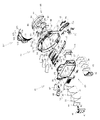
次に、上記センターフレーム21について図2乃至図4を参照しつつ説明する。センターフレーム21は、中央部が前後方向に貫通した前ベース枠22及び後ベース枠23を備え、全体として枠体形状となっている。
【0048】
後ベース枠23の中央部には前記液晶表示部20に対応した略矩形状の窓枠部24が形成されている。窓枠部24の周囲には、その前端部から遊技盤5に沿って略平板状の上板部25、右板部26、左板部27及び下板部28が延出されている。
【0049】
上板部25は、その左側周縁部が窓枠部24の左上端部近傍から上方に向かって延び、上側周縁部が窓枠部24の左端部近傍から左右方向略中央部までの範囲にかけてほぼ窓枠部24の上辺部に沿って形成され、右側周縁部が前記上側周縁部の右端部近傍から窓枠部24の右上端部近傍に向けて下方に傾斜しているように形成されている。
【0050】
右板部26は、その上側周縁部が上板部25の右側周縁部から連なって右方向に向かって下方へ傾斜し、右側周縁部が上側周縁部の右端部から窓枠部24の右下端部近傍に向けて緩やかに湾曲しているように形成され、全体として下方に向かうにつれ先細りした形状となっている。
【0051】
左板部27は、その上側周縁部が窓枠部24左上端部近傍から左方向に向かって延び、左側周縁部が窓枠部24の上端部近傍から上下方向略中央部をやや過ぎた位置までの範囲においてほぼ窓枠部24の左辺部に沿って形成され、下側周縁部が左側周縁部の下端部から窓枠部24の左下端部近傍に向けて緩やかに湾曲しているように形成されている。
【0052】
下板部28の下側周縁部は左右両板部26,27の周縁部から連なるように下に凸の略円弧形状となっている。
【0053】
さて、右板部26には前後方向に貫通した右開口部30が設けられている。右開口部30は右板部26に対しかなりの領域を占め、その形状も右板部26と略同一形状となっている。右開口部30には当該右開口部30と略相似形状の右透光パネル31が取着されている。右透光パネル31は、略同一形状の前パネル32、後パネル33及び保護パネル34が重ね合わされた複層構造となっている。重ね合わせの順序は前方より保護パネル34、前パネル32、後パネル33の順となっている。各パネル32,33,34は、本実施の形態においては透光性を有する透明又は半透明の樹脂により形成されている。但し、前パネル32、後パネル33は、透光性を有する部材で有れば、樹脂に限らず他の材質のもの例えばガラス等でもよい。
【0054】
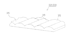
図5に示すように、前パネル32の前面側(光の出射面側)、後パネル33の背面側(光の入射面側)には、それぞれ複数の直線状凸部35が設けられている。本実施の形態では、前後両パネル32,33における各直線状凸部35はその断面形状が略半円形状をなし、所定方向に沿って延びている。詳しくは、前パネル32では、鉛直方向に対して斜め45度左下がりの傾きに沿って延びた複数の直線状凸部35が列状に並んでいる。後パネル33では、鉛直方向に対して斜め45度右下がりの傾きに沿って延びた複数の直線状凸部35が列状に並んでいる。従って、前後両パネル32,33が重ね合わされた状態では、前後両パネル32,33に設けられた直線状凸部35は互いに略直交した状態となる。なお、前後両パネル32,33における直線状凸部35の配列ピッチは後述するLED43の大きさと比較してより微細なものとなっている。
【0055】
同様に、左板部27にも左開口部37が設けられ、当該左開口部37には左透光パネル38が取着されている。なお、左透光パネル38の構成は、上記右透光パネル35と略同一のためその説明を省略する。
【0056】
一方、後ベース枠23の背面側には各種電飾部材が取着されている。詳しくは、右板部26の背面側には電飾部材を配設するための右側部取付部材40が取着されている。右側部取付部材40は、電飾部材が係止される係止板41と、当該係止板41から前方に向けて突出した複数の支柱部42とを有している。右側部取付部材40は、各支柱部42の先端が右板部26の背面に当接した状態で所定の固定手段により固定されている。従って、電飾部材が前記右透光パネル31から所定間隔をおいて配置されることとなる。本実施の形態では、電飾部材として、係止板41の前面側において複数のLED43を有する右側部LED基板44が取着されている。
【0057】
一方、左板部27の背面側にも同様に、左側部LED基板45が左側部取付部材46を介して取着されている。従って、左側部LED基板45も同様に左透光パネル38から所定間隔をおいて配置されることとなる。
【0058】
さらに、上板部25の右側周縁部及び右板部26の上側周縁部の上方の後方位置において、右上側部LED基板47が右上部取付部材48を介して取着されている。なお、右上部取付部材48も係止板50及び複数の支柱部49を有しており、各支柱部49の先端は上板部25又は右板部26の背面に当接状態で固定されている。また、右上部取付部材48の係止板50は、前記右側部取付部材40の係止板41と略面一となるように配置されている。従って、右上部LED基板47の配置位置と、右側部LED基板44の配置位置とは前後方向に略同一位置となっている。
【0059】
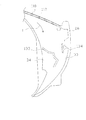
さて、前ベース枠22は、その下部において上記遊技盤5の開口部にはめ込まれる嵌込み部51と、その上部において嵌込み部51と連なった上梁部52とを備えている。嵌込み部51は、右板部26の右側周縁部、左板部27の左側周縁部及び下板部28の下側周縁部に沿って形成され、略U字形状となっている。嵌込み部51及び上梁部52の周囲には遊技盤5面上に配設される複数のフランジ部53が形成されている。
【0060】
上梁部52は、その両側部が嵌込み部51の左右両端部より略上方に向かって延出され、その中央部が上に凸の略円弧形状となっている。上梁部52の前面側には、当該上梁部52のほぼ全域において、前方に向けて突出した天井部54が設けられている。天井部54の頂上部には遊技球Bが通過可能な開口部55が形成されている。
【0061】
上梁部52の左側部には内方向に延出された下垂部57が設けられている。下垂部57の下側周縁部は、上梁部52の左端部近傍から右方向に向けて延び、右方向に向かうにつれ上方に向けて緩やかに湾曲し、さらに右方向に向かうにつれ徐々にその傾きが略水平方向、斜め右下方向へとなるように緩やかに湾曲した形状となっており、その右端部が前記開口部55の右端部の下方位置をやや越えた位置まで達している。また、開口部55の右端部近傍から下方へ延出された下垂部57の右側周縁部は、所定位置より前記下側周縁部の右端部に向けて斜め右下がりに傾斜している。
【0062】
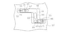
下垂部57の前面側には各種役物が取着され、背面側には前記役物を駆動させる駆動機構が設けられている。詳しくは、図6に示すように、下垂部57の背面側には取付凹部60が形成されている。取付凹部60内には駆動伝達部材61が左右方向に摺動可能に取着されている。駆動伝達部材61は、上下方向に延びる縦軸部62と、縦軸部62の下端部より左側(図6における右側)へ摺動方向に沿って延びる左操作部63と、縦軸部62の上端部より右側へ摺動方向に沿って延びる右操作部64とから構成されている。
【0063】
縦軸部62には前後方向に貫通し上下方向に長い縦長孔65が設けられている。左操作部63と右操作部64にはそれぞれ前後方向に貫通し摺動方向に長い左長孔66、右長孔67が形成されている。当該長孔66,67にはそれぞれ下垂部57の背面側から突出したボス69,70が差し込まれている。
【0064】
下垂部57には、ボス69の左側、ボス70の右側においてそれぞれ前後方向に貫通し摺動方向に長い略円弧状の左円弧長孔71、右円弧長孔72が形成されている。各円弧長孔71,72は下に凸となる円弧形状となっている。
【0065】
円弧長孔71,72に対応するように、左操作部63及び右操作部64の先端部にはそれぞれ前後方向に貫通し上下方向に長い左端長孔73、右端長孔74が形成されている。
【0066】
下垂部57の背面側には、前記取付凹部60を覆い、駆動伝達部材61の脱落を防止する取付カバー75が取着されている(図2等参照)。取付カバー75には、上記縦軸部65の位置に対応して前後方向に貫通した略円形の開口部75aが形成されている。
【0067】
取付カバー75の背面側には開口部75aの後方においてモータ76が取着されている。モータ76の回転軸の先端部には開口部75aに差し込まれる円盤体77が取着されている。円盤体77の前面側にはモータ76の回転軸線上から外れた位置において前方へ突出した棒状凸部78が設けられている。棒状凸部78は上記縦長孔65に差し込まれている。
【0068】
一方、下垂部57の前面側には複数の薄板状の装飾パネル80が取着され、その前面側には上記左円弧長孔71、右円弧長孔72の位置に対応してそれぞれ、宇宙船をモチーフにした大可動部材81、中可動部材82が回動可能に軸支されている。なお、各装飾パネル80には左円弧長孔71、右円弧長孔72に対応した図示しない孔部が形成されている。さらに、中可動部材82の右側には、宇宙船をモチーフにした小可動部材83が取着されている。下垂部57の前面側には、透明又は半透明の役物カバー85が取着されている。役物カバー85は、下垂部57と略同一形状で断面凹形状に構成されており、その右側壁部86は下垂部57の右側周縁部に沿って傾斜している。
【0069】
ここで大可動部材81及び中可動部材82に関連した構成部分について詳しく説明する。大可動部材81及び中可動部材82の上部にはそれぞれ前後方向に貫通した軸孔87,88が形成されている。軸孔87,88にはそれぞれ軸棒89,90が差し込まれている。下垂部57の前面側及び役物カバー85の背面側には、軸棒89を受ける一対の軸受け部91,92、軸棒90を受ける一対の軸受け部93,94がそれぞれ相対向するように形成されている。
【0070】
大可動部材81及び中可動部材82の背面側には、それぞれ軸孔87,88の下方において、上記左円弧長孔71、右円弧長孔72の位置に対応するように棒状の操作子95,96が後方に向けて突出形成されている。操作子95,96はそれぞれ左円弧長孔71、右円弧長孔72を介して上記左端長孔73、右端長孔74に差し込まれている。
【0071】
上記構成に基づき、モータ76が回転すると、この回転動作が円盤体77を介して駆動伝達部材61に伝達され、駆動伝達部材61が左右方向に往復動する。そして、駆動伝達部材61の往復動作が操作子95,96を介して大可動部材81、小可動部材83に伝達される。大可動部材81、小可動部材83は軸棒89,90を中心に往復回動する。
【0072】
さて、下垂部57の下部には、前ベース枠22の左右方向略中央部において報知表示部100が取着されている。報知表示部100は、下垂部57に固定された基部101と、基部101の前面側に取着された透光性レンズ102と、透光性レンズ102の前面側を覆う被覆部103と、基部101の背面側に取着された報知用LED基板104とにより構成されている。
【0073】
報知用LED基板104には複数のLED105が設けられている。基部101には各LED105に対応した複数の孔部106が形成され、透光性レンズ102の前面側には各LED105に対応して複数の絵柄が象られている。被覆部103には前記各絵柄と略同一形状の絵柄孔107が形成されている。
【0074】
下垂部57の右側には、上記嵌込み部51の右端部より上記右板部26の上側周縁部に沿って延出された天板部110が設けられている。天板部110の先端部は下垂部57の右端部に連接されている。天板部110の略中央部には上下方向に貫通した監視孔112が形成されている。これにより、下垂部57の右側において長窓部113が形成される。長窓部113は上記右上部LED基板47の前方に位置している。
【0075】
長窓部113には当該長窓部113と略同一形状の右上透光パネル115が取着されている。なお、右上透光パネル115の構成は、上記右透光パネル31や左透光パネル38とほぼ同様のためその説明を省略する。
【0076】
さて、前ベース枠22の右側部には、前記右透光パネル31及び右上透光パネル115の前面側を覆うように透光性を有するレンズカバー117が取着されている。本実施の形態では、レンズカバー117と、右透光パネル31及び右上透光パネル115とよって囲まれた空間部分によって、上記開口部55を通過した遊技球Bをセンターフレーム21下部へと案内する遊技球流路が形成される。
【0077】
レンズカバー117は、その前面部において、前ベース枠22の右内側部に沿って湾曲形成された右レンズ部118と、右レンズ部118の左側部に沿って形成された中レンズ部119と、中レンズ部119の左側部に沿って形成された左レンズ部120とを有している。
【0078】
各レンズ部118,119,120は、その上端部が上記天井部54にまで達しており、左右方向の幅が下方に向かうにつれ先細りしている。右レンズ部118及び中レンズ部119の下端部は上記窓枠部24の右下端部近傍にまで達しており、左レンズ部120の下端部は右中レンズ部118,119の下端部よりやや上方に位置している。
【0079】
また、前後方向に対して、各レンズ部118,119,120は、下方に向かうにつれその前面部がより後方へ位置するように緩やかに湾曲している。各レンズ部118,119,120の上端部近傍における前面部は天井部54の前端部近傍に位置している。右レンズ部118及び中レンズ部119の下端部は窓枠部24の前後方向略中央部に位置しており、左レンズ部120の下端部は右板部26の前面部近傍に位置している。
【0080】
左レンズ部120の左側部には、当該左側部から後方へ延出された左側壁部121が設けられている。左側壁部121の外面には前後方向に沿って延びた複数の直線状凸部122が列状に並んで形成されている。
【0081】
左側壁部121は、上記下垂部57の右端部(上記天板部110)より上部分が下垂部57の形状に合わせて切り欠かれ当該下垂部57に当接し、それより下部分が前記右板部26に当接している。
【0082】
左レンズ部120の右側部と中レンズ部119の左側部との間には段差が形成されており、中レンズ部119がより前方に位置している。当該段差部分には中側壁部123が形成されている。
【0083】
同様に、中レンズ部119の右側部と右レンズ部118の左側部には段差が形成されており、右レンズ部118がより前方へ位置している。当該段差部分には右側壁部124が形成されている。また、中右側壁部123,124の外面には、左側壁部121同様に、複数の直線状凸部122が形成されている。なお、中側壁部123の下端部は遊技球Bが通過可能なように切り欠かれている。
【0084】
左レンズ部120の上端部には、上記天井部54と役物カバー85との前面側の隙間を覆う被覆部125が設けられている。
【0085】
レンズカバー117の背面側には、右レンズ部118及び中レンズ部119を仕切る右リブ126と、中レンズ部119及び左レンズ部120を仕切る左リブ127とが設けられている。これにより、レンズカバー117には、右レンズ部118、中レンズ部119、左レンズ部120の背面側において、それぞれ遊技球Bが通過可能な右溝部128、中溝部129、左溝部130が形成される。
【0086】
右リブ126及び左リブ127は、上記天板部110より上部分が切り欠かれ上記右上透光パネル115に当接し、それより下部分の一部が上記右透光パネル(保護パネル34)に当接している。
【0087】
右リブ126の長手方向略中央部より下部全域が切り欠かれ、右溝部128と中溝部129との間を遊技球Bが通過可能となっている。また、左リブ127の下端部近傍における一部分が切り欠かれ、中溝部129と左溝部130との間を遊技球Bが通過可能となっている。
【0088】
一方、保護パネル34の前面側には、右リブ126及び左リブ127の切り欠き部分に対応して、誘導リブ133と規制リブ134とが設けられている。誘導リブ133は、遊技球Bを左溝部130から中溝部129へと誘導可能なように段階的にその傾斜角度を変化させつつ右下がりに形成されている。規制リブ134は、誘導リブ133によって誘導される遊技球Bの右方向へ動きを規制するように上下方向に沿って形成されている。
【0089】
上記構成により、上記開口部55を通過した遊技球Bは、上記役物カバー85の右側壁部86に沿って右方向へ流下し、左溝部130内へと導かれる。当該遊技球Bは左溝部130に沿って流下し、誘導リブ133及び規制リブ134によって中溝部129へと導かれる。そして、当該遊技球Bは右溝部128又は中溝部129に沿って流下し、上記中側壁部123の切り欠き部より後述するステージ部145へと排出される。
【0090】
一方、後ベース枠22の左板部27(左透光パネル38)の前面側には、装飾カバー138が取着されている。装飾カバー138は、上記レンズカバー117の下部と略左右対称形状となっている。
【0091】
さて、嵌込み部51の下部には、上記下板部28の下側周縁部の形状に合わせて凹部140が形成されている。凹部140の左右方向略中央部には、遊技球Bを上記作動チャッカー13の方へ誘導可能な誘導路141が形成されている。誘導路141は、後部が遊技球Bほぼ1つ分の幅に、前部が遊技球B複数個分の幅に構成されている。また、誘導路141の前端部には遊技球Bが通過可能な開口部142が形成されている。
【0092】
嵌込み部51の下部には、凹部140を覆うステージ部145が取着されている。ステージ部145は、左右方向に沿って左右両端部から中央部に向かうにつれ下方へ傾斜し、さらに中央に向かうにつれ上方へ傾斜し、左右方向中央部が凸状に形成されている。当該左右方向中央部(頂上部)には後方に向けて傾斜した傾斜部146が形成されている。一方、後ベース枠23には、傾斜部146に対応するように、窓枠部24及び下板部28の左右方向略中央部において誘導溝147が形成されている。誘導溝147は誘導路141の後部に連通している。
【0093】
上記構成により、例えば上記遊技球流路より排出された遊技球Bはステージ部145上を転動する。一部の遊技球Bは傾斜部146、誘導溝147及び誘導路141を通って上記作動チャッカー13の方へ誘導される。
【0094】
以上、センターフレーム21について詳述したが、本実施の形態における特徴的な構成は、右板部26の上側周縁部に沿って延出された天板部110の略中央部に監視孔112が設けられていることにある(図4参照)。
【0095】
上述したように、右透光パネル31を構成する保護パネル34の前面側には、レンズカバー117の背面側に設けられた右リブ126及び左リブ127の切り欠き部分に対応して、誘導リブ133と規制リブ134とが設けられている。右板部26に、保護パネル34が取り付けられた様子を、図7に示した。
【0096】
センターフレーム21が組み立てられた状態にあっては、レンズカバー117の右リブ126及び左リブ127は、天板部110より下部分の一部が保護パネル34に当接する。したがって、右リブ126及び左リブ127の切り欠き部分に配置される誘導リブ133及び規制リブ134は、丁度、天板部110の下方に配置されることになる。
【0097】
このとき、上記監視孔112は、誘導リブ133及び規制リブ134の少なくとも一部を視認可能となるように、天板部110の略中央部分に設けられている。本実施の形態では、図7に示すように、誘導リブ133の僅かに左側上方に設けられている。これは遊技球Bの各リブ133,134へ向かう流下方向Lの上流側位置となっている。図7中には、天板部110を二点鎖線で示し、天板部110に設けられる監視孔112を破線で示した。
【0098】
なお、本実施の形態におけるレンズカバー117と、天板部110と、右透光パネル31及び右上透光パネル115とよって形成される囲まれた空間部分によって形成される遊技球流路が、上述した手段における「遊技球流路」に相当する。また、誘導リブ133及び規制リブ134が「流下状態変更部」に相当し、ステージ部145が「ステージ部」に相当する。そして、天板部110に設けられた監視孔112が「開口部」に相当する。
【0099】
次に、本実施の形態におけるパチンコ機1の発揮する効果を説明する。
【0100】
本実施の形態では、保護パネル34に設けられた誘導リブ133及び規制リブ134の少なくとも一部を視認可能となるように、天板部110の略中央部分に監視孔112が設けられている(図7参照)。そのため、監視孔112を介して誘導リブ133及び規制リブ134に対する保守を容易に行うことができる。
【0101】
例えば、監視孔112は清掃孔として利用することができ、その場合、綿棒などを用いることにより、監視孔112を介して、誘導リブ133及び規制リブ134の清掃を行うことができる。その結果、誘導リブ133や規制リブ134が汚れることを適切に防止できる。これによって、遊技球Bがつまったりする可能性を低くすることができ、遊技の興趣を損なうことを防止できる。
【0102】
特に近年、遊技盤5の中央に配置される液晶表示部20の大型化により、遊技球の転動領域が狭くなっている。そのため、ステージ部145に遊技球Bを誘導して、ステージ部145上で遊技球Bを転動させ、その挙動により遊技者の興趣を高めるようにパチンコ機1を構成することが多い。そのため、センターフレーム21の上部からステージ部145へ遊技球Bを導くための遊技球流路の重要性が高まり、遊技球Bの遊技球流路の通過確率が高くなっている。これにより、誘導リブ133及び規制リブ134に遊技球Bが接触する回数が多くなっており、この部分に埃などが付着する可能性が高くなっているのである。したがって、誘導リブ133及び規制リブ134に付着した汚れを適切に除去できるような監視孔112を設けることは、極めて大きな効果を奏する。
【0103】
また例えば、監視孔112は点検孔として利用することができ、その場合、誘導リブ133や規制リブ134が汚れているか否か、あるいは、破損しているか否かを点検することができる。これによって、適切なタイミングで清掃を行うことができ、また、破損した状態にあることを速やかに発見することができる。特に本実施の形態では、監視孔を介して誘導リブ133又は規制リブ134の少なくとも一部が視認可能となるように、監視孔112が設けられているため、作業者は自分の目で見て点検を行うことができる。その結果、適切な清掃や点検が可能になる。
【0104】
また、監視孔112は、天板部110、すなわち誘導リブ133及び規制リブ134に対し、遊技球Bの流下方向Lの上流側に設けられている。特に破損は、球勢によって大きな衝撃がかかる部分に生じやすい。この点、遊技球Bの上流側に監視孔112を設けているため、適切な破損状態の点検が可能になる。
【0105】
一方、監視孔112から、例えば、棒状の部材を差し込んで、つまってしまった遊技球を遊技球流路からステージ部145へ排出することが可能になる。つまり、遊技の途中に発生する不具合にも迅速に対応することができ、遊技の興趣が損なわれることを防止できる。
【0106】
尚、上述した実施の形態の記載内容に限定されず、例えば次のように実施してもよい。
【0107】
(a)上記実施の形態では、監視孔112を、天板部110の略中央部分に設けている。しかし、誘導リブ133や規制リブ134の保守を行うことができればよく、監視孔112の配置位置は、天板部110に限定されるものではない。
【0108】
(b)また、監視孔112は、誘導リブ133及び規制リブ134の清掃、点検、さらに、遊技球Bがつまった場合の排出作業に利用されていたが、いずれか一つを可能にするようなものとしてもよい。あるいは、これら以外の保守目的に利用されるものとしてもよい。
【0109】
(c)誘導リブ133は、段階的にその傾斜角度を変化させつつ右下がりに形成されており、規制リブ134は、誘導リブ133によって誘導される遊技球Bの右方向へ動きを規制するように上下方向に沿って形成されていた(図7参照)。そして、これら誘導リブ133及び規制リブ134は、遊技球Bの流下速度及び流路の変更を担うものであったが、このような形状の誘導リブ133や規制リブ134に限定されるものではない。つまり、「流下状態変更部」は、遊技球Bに変化を与えるべく流下状態を変更する機能を有するものであればよい。
【0110】
(d)上記実施の形態では、液晶表示部20の周囲を囲むセンターフレーム21を枠体として採用したが、他の役物を囲むものを枠体として採用することもできる。
【0111】
(e)上記実施の形態では、可変表示装置14の表示部として液晶表示部20を採用している。しかし、これに限らず、他にも、CRT、ドットマトリックス、LED(エレクトロルミネッセンス)、蛍光表示管等を可変表示装置14の表示部として用いてもよい。
【0112】
(f)上記実施の形態とは異なるタイプのパチンコ機にも適用してもよい。従って、可変表示装置14のないパチンコ機にも応用できる。また、本発明は、パチンコ機以外にも雀球、アレンジボール等の遊技機にも応用可能である。
【図面の簡単な説明】
【図1】一実施の形態におけるパチンコ機を示す正面図である。
【図2】センターフレームを示す斜視図である。
【図3】センターフレームを示す正面分解斜視図である。
【図4】センターフレームを示す背面分解斜視図である。
【図5】直線状凸部を示す図である。
【図6】駆動伝達部材等を示す図である。
【図7】保護パネルに設けられたリブと、天板部に設けられた監視孔との正面からの位置関係を示す模式図である。
【符号の説明】
1…遊技機としてのパチンコ機、5…遊技盤、13…作動チャッカー、14…可変表示装置、20…液晶表示部、21…枠体としてのセンターフレーム、22…前ベース枠、23…後ベース枠、26…右板部、30…右開口部、31…右透光パネル、34…保護パネル、110…天板部、112…開口部としての監視孔、115…右上透光パネル、117…レンズカバー、133…流下状態変更部としての誘導リブ、134…流下状態変更部としての規制リブ、L…流下方向。[0001]
BACKGROUND OF THE INVENTION
The present invention relates to a gaming machine such as a pachinko machine.
[0002]
[Prior art]
Conventionally, as a type of gaming machine, a pachinko machine in which various gaming states are derived due to the behavior of a gaming ball on a gaming board surface is known. A player who plays a game with such a pachinko machine expects the derivation of a predetermined game state, and pays attention to the behavior of the game ball on the game board surface.
[0003]
In order to make the player visually recognize the behavior of the game ball and improve its interest, a pachinko machine having a stage on which the game ball can roll can be found at the lower part of the center frame surrounding the variable display device. Such a center frame may be provided with a game ball channel for guiding the game ball from the upper part to the stage.
[0004]
Furthermore, in order to suppress the speed of the game ball flowing down through the game ball flow path, or to change the movement of the game ball, a flow-down state in which the flow state of the game ball is changed inside the game ball flow path. It is possible to provide a change part.
[0005]
[Problems to be solved by the invention]
In many cases, the flow-down state changing unit is contaminated with dust or the like due to repeated contact with the game ball. If dirt is attached to the flow-down state changing portion, there is a high possibility that a game ball is clogged in this portion, which may impair the fun of the game.
[0006]
However, it is difficult to maintain the flow-down state changing unit.
[0007]
It is an object of the present invention to provide a gaming machine that can be easily maintained with respect to the flow-down state changing unit disposed in such a game ball flow path.
[0008]
[Means for Solving the Problems and Effects of the Invention]
In order to achieve the above object , in the present invention,
A center frame is provided for the game board and surrounds the periphery of a variable display device capable of variably displaying identification information.
The center frame is
A stage part provided at the lower part of the center frame, on which the gaming ball can roll,
A gaming machine provided on a side portion of the center frame and having a game ball flow path capable of guiding the game ball flowing in from the entrance portion to the stage portion via the exit portion,
Inside the game ball flow path, it has a flow state changing unit for changing the flow state of the game ball,
Furthermore, the center frame is provided with an opening on the upstream side in the game ball flow direction from the flow state changing unit, separately from the inlet / outlet portion of the game ball flow path, Make at least a part of the state change part visible,
The entrance portion of the game ball channel is provided on the upper side or the side portion of the center frame on the front side of the front surface of the game board in the state of attachment of the center frame to the game board,
The opening is provided in the center frame on the rear side of the front surface of the game board when the center frame is attached to the game board.
In addition, the flow-down state changing unit may be a rib that protrudes from the rear panel constituting the game ball flow path to the front side and that changes the flow speed and flow direction of the game ball.
The gaming machine may be a pachinko machine.
According to the present invention, maintenance for the flow-down state changing unit arranged in the game ball flow path is facilitated.
[0009]
DETAILED DESCRIPTION OF THE INVENTION
Inside the game ball flow path, it has a flow state changing unit for changing the flow state of the game ball,
Furthermore, a gaming machine, wherein an opening for maintaining the flow-down state changing unit is provided separately from the inlet / outlet of the game ball channel.
[0010]
According to the
[0011]
Note that the change in the flow-down state includes a change in the flow-down speed of the game ball, a change in the flow path, and the like (the same applies to the following means). In addition, the above-described game ball channel may be a substantially linear channel, or may be a curved channel (the same applies to the following means). In particular, when the game ball flow path is curved, maintenance through the inlet / outlet is difficult, which is very effective.
[0012]
Mean 2. A frame provided in a game area of the game board, the frame is attached to a lower portion of the frame, and a stage portion on which a game ball can roll on its upper surface; and a side of the frame A gaming machine provided with a gaming ball flow path that is provided in a part and is capable of guiding a gaming ball flowing in from an inlet part to the stage part through an outlet part,
Inside the game ball flow path, it has a flow state changing unit for changing the flow state of the game ball,
Furthermore, the gaming machine is characterized in that an opening for maintaining the flow-down state changing part is provided in the frame body separately from the inlet / outlet part of the game ball channel.
[0013]
The means 2 includes a frame body, and the frame body includes a stage portion that allows rolling of the game ball, and a game ball flow path that guides the game ball flowing in from the inlet portion to the stage portion. .
[0014]
Here, in particular, an opening for maintaining the flow state changing portion in the game ball channel is provided in the frame separately from the inlet and outlet portions of the game ball channel. Even if the state change unit is arranged, the flow state change unit can be easily maintained through the opening. In particular, when the game ball flow path is curved, maintenance through the inlet / outlet is difficult, which is very effective.
[0015]
In addition, it is good also as "the said entrance part being provided in the upper part or side part of the said frame".
[0016]
Means 3. In the means 2, the frame body is constituted by a center frame surrounding the periphery of the variable display device capable of variably displaying the identification information.
[0017]
Means 4. In the means 2 or 3, the opening is provided so that maintenance of the flow-down state changing portion is possible in a state where the frame is attached to the game area.
[0018]
According to the means 4, since maintenance through the opening can be performed without removing the frame body provided in the game area from the game area, the flow state changing unit can be easily maintained.
[0019]
[0020]
According to the
[0021]
As a result, it is possible to appropriately prevent dirt and the like from adhering due to repeated contact of the game balls and soiling the flow-down state changing unit. As a result, the possibility that the game ball is clogged can be reduced, and the interest of the game can be prevented from being impaired.
[0022]
[0023]
According to the
[0024]
Mean 7 In the
[0025]
According to the means 7, it is possible to check whether or not the flow state changing portion is dirty through the inspection hole, and it is possible to perform cleaning or the like at an appropriate timing.
[0026]
[0027]
It is conceivable that the flow-down state changing unit is damaged due to repeated contact with the game ball. In this respect, according to the
[0028]
Means 9. In any one of the
[0029]
According to the means 9, since the opening is a flow-down forced hole for allowing the game ball remaining in the flow-down state changing portion to flow down again, the game ball is jammed in the flow-down state changing portion inside the curved game ball flow path. Even in such a case, the game ball can flow down again through the opening. For example, a rod-shaped member is inserted and the game ball is discharged from the exit portion of the game ball channel. That is, it is possible to quickly cope with a problem that occurs in the middle of a game, and to prevent the game's interest from being impaired.
[0030]
Means 10. In any one of the
[0031]
In particular, breakage of the flow-down state changing portion is likely to occur in a portion where a large impact is applied due to the sphere. In this respect, according to the means 10, since the opening is provided on the upstream side in the flow-down direction of the game ball, it is possible to easily check the portion that is easily damaged. As a result, appropriate inspection can be performed.
[0032]
Means 11. In any one of the
[0033]
The inspection through the opening as described above may be performed using, for example, a rod-shaped member such as a cotton swab. On the other hand, according to the means 11, since the opening is provided so that at least a part of the flow-down state changing portion can be visually recognized, the operator should inspect the flow-down state changing portion with his own eyes. Can do. As a result, it is possible to appropriately clean and check the flow-down state changing unit.
[0034]
Means 12. In any one of means 2 to 10, the opening is provided so that at least a part of the flow-down state changing portion can be visually recognized through the opening in a state where the frame is attached to the game area. A featured gaming machine.
[0035]
According to the means 12, in addition to the effect of the means 11, the flow state changing part can be visually recognized without removing the frame provided in the game area from the game area. It becomes easy.
[0036]
Means 13. In any one of
[0037]
Hereinafter, an embodiment of a pachinko gaming machine (hereinafter simply referred to as “pachinko machine”) will be described in detail with reference to the drawings.
[0038]
As shown in FIG. 1, the
[0039]
A glass door frame 4 is provided on the front side of the front frame 3 so as to be freely opened and closed. A
[0040]
Below the glass door frame 4, an
[0041]
A plurality of openings are formed in the
[0042]
On one side of the
[0043]
The
[0044]
The liquid crystal display unit 20 displays three display rows, for example, a left symbol row, a middle symbol row, and a right symbol row. Each symbol row is composed of a plurality of symbols as identification information, and these symbols are variably displayed so as to scroll for each symbol row.
[0045]
More specifically, the design of the liquid crystal display unit 20 of the
[0046]
As is well known, a predetermined number of prize balls (game balls) are placed on the
[0047]
Next, the
[0048]
A substantially rectangular
[0049]
The
[0050]
The
[0051]
The
[0052]
The lower peripheral edge portion of the
[0053]
The
[0054]
As shown in FIG. 5, a plurality of linear
[0055]
Similarly, a
[0056]
On the other hand, various electrical decoration members are attached to the back side of the
[0057]
On the other hand, the left
[0058]
Furthermore, an upper right
[0059]
The
[0060]
The
[0061]
A drooping
[0062]
Various accessories are attached to the front side of the hanging
[0063]
The
[0064]
The drooping
[0065]
Corresponding to the arc long holes 71, 72, left end
[0066]
A mounting
[0067]
A
[0068]
On the other hand, a plurality of thin plate-like
[0069]
Here, the components related to the large
[0070]
On the back side of the large
[0071]
Based on the above configuration, when the
[0072]
A
[0073]
A plurality of LEDs 105 are provided on the
[0074]
On the right side of the hanging
[0075]
An upper right
[0076]
Now, a
[0077]
The
[0078]
The upper ends of the
[0079]
Further, with respect to the front-rear direction, each of the
[0080]
On the left side portion of the
[0081]
The
[0082]
A step is formed between the right side portion of the
[0083]
Similarly, a step is formed on the right side portion of the
[0084]
A covering
[0085]
On the back side of the
[0086]
The
[0087]
The entire lower portion is cut out from the substantially longitudinal central portion of the
[0088]
On the other hand, a
[0089]
With the above configuration, the game ball B that has passed through the
[0090]
On the other hand, a
[0091]
A
[0092]
A
[0093]
With the above configuration, for example, the game ball B discharged from the game ball flow path rolls on the
[0094]
Although the
[0095]
As described above, on the front side of the
[0096]
In the assembled state of the
[0097]
At this time, the
[0098]
Note that the game ball flow path formed by the enclosed space portion formed by the
[0099]
Next, the effect which the
[0100]
In the present embodiment, a
[0101]
For example, the
[0102]
Particularly in recent years, the rolling area of game balls has become narrow due to the increase in the size of the liquid crystal display unit 20 disposed in the center of the
[0103]
Further, for example, the
[0104]
The
[0105]
On the other hand, for example, a rod-shaped member can be inserted from the
[0106]
In addition, it is not limited to the description content of embodiment mentioned above, For example, you may implement as follows.
[0107]
(A) In the embodiment described above, the
[0108]
(B) In addition, the
[0109]
(C) The
[0110]
(D) In the above-described embodiment, the
[0111]
(E) In the above embodiment, the liquid crystal display unit 20 is employed as the display unit of the
[0112]
(F) You may apply to the pachinko machine of a different type from the said embodiment. Therefore, the present invention can also be applied to a pachinko machine without the
[Brief description of the drawings]
FIG. 1 is a front view showing a pachinko machine according to an embodiment.
FIG. 2 is a perspective view showing a center frame.
FIG. 3 is a front exploded perspective view showing a center frame.
FIG. 4 is a rear exploded perspective view showing a center frame.
FIG. 5 is a diagram showing a linear convex portion.
FIG. 6 is a diagram showing a drive transmission member and the like.
FIG. 7 is a schematic diagram showing a positional relationship from the front of a rib provided on the protective panel and a monitoring hole provided on the top plate portion.
[Explanation of symbols]
DESCRIPTION OF
Claims (3)
該センターフレームは、
当該センターフレームの下部に設けられ、自身の上面を遊技球が転動可能となっているステージ部と、
当該センターフレームの側部に設けられ、入口部から流入した遊技球を出口部を介し前記ステージ部へと案内可能になっている遊技球流路とを具備する遊技機であって、
前記遊技球流路内部に、前記遊技球の流下状態を変更する流下状態変更部を有しており、
さらに、前記センターフレームには、前記遊技球流路の入口部・出口部とは別に、前記流下状態変更部よりも遊技球流下方向の上流側に開口部を設け、当該開口部から、前記流下状態変更部の少なくとも一部を視認可能とし、
前記遊技球流路の入口部は、前記センターフレームの前記遊技盤への取付状態における当該遊技盤の前面よりも前側において前記センターフレームの上部又は側部に設けられており、
前記開口部は、前記センターフレームの前記遊技盤への取付状態における当該遊技盤の前面よりも後側において前記センターフレームに設けられていることを特徴とする遊技機。A center frame is provided for the game board and surrounds the periphery of a variable display device capable of variably displaying identification information.
The center frame is
A stage unit for lower to set the vignetting of the center frame, game balls to the upper surface of itself is a rollable,
A gaming machine provided on a side portion of the center frame and having a game ball flow path capable of guiding the game ball flowing in from the entrance portion to the stage portion via the exit portion,
Inside the game ball flow path, it has a flow state changing unit for changing the flow state of the game ball,
Furthermore, the center frame is provided with an opening on the upstream side in the game ball flow direction from the flow state changing unit, separately from the inlet / outlet portion of the game ball flow path, Make at least a part of the state change part visible ,
The entrance portion of the game ball channel is provided on the upper side or the side portion of the center frame on the front side of the front surface of the game board in the state of attachment of the center frame to the game board,
The gaming machine according to claim 1, wherein the opening is provided in the center frame on the rear side of the front surface of the game board when the center frame is attached to the game board .
Priority Applications (1)
| Application Number | Priority Date | Filing Date | Title |
|---|---|---|---|
| JP2002221113A JP4356290B2 (en) | 2002-07-30 | 2002-07-30 | Game machine |
Applications Claiming Priority (1)
| Application Number | Priority Date | Filing Date | Title |
|---|---|---|---|
| JP2002221113A JP4356290B2 (en) | 2002-07-30 | 2002-07-30 | Game machine |
Related Child Applications (1)
| Application Number | Title | Priority Date | Filing Date |
|---|---|---|---|
| JP2009050124A Division JP4831184B2 (en) | 2009-03-04 | 2009-03-04 | Game machine |
Publications (3)
| Publication Number | Publication Date |
|---|---|
| JP2004057552A JP2004057552A (en) | 2004-02-26 |
| JP2004057552A5 JP2004057552A5 (en) | 2005-10-27 |
| JP4356290B2 true JP4356290B2 (en) | 2009-11-04 |
Family
ID=31941530
Family Applications (1)
| Application Number | Title | Priority Date | Filing Date |
|---|---|---|---|
| JP2002221113A Expired - Fee Related JP4356290B2 (en) | 2002-07-30 | 2002-07-30 | Game machine |
Country Status (1)
| Country | Link |
|---|---|
| JP (1) | JP4356290B2 (en) |
Cited By (1)
| Publication number | Priority date | Publication date | Assignee | Title |
|---|---|---|---|---|
| JP2009112866A (en) * | 2009-03-04 | 2009-05-28 | Sanyo Product Co Ltd | Game machine |
Families Citing this family (1)
| Publication number | Priority date | Publication date | Assignee | Title |
|---|---|---|---|---|
| JP2006061234A (en) * | 2004-08-25 | 2006-03-09 | Daiichi Shokai Co Ltd | Game machine |
-
2002
- 2002-07-30 JP JP2002221113A patent/JP4356290B2/en not_active Expired - Fee Related
Cited By (1)
| Publication number | Priority date | Publication date | Assignee | Title |
|---|---|---|---|---|
| JP2009112866A (en) * | 2009-03-04 | 2009-05-28 | Sanyo Product Co Ltd | Game machine |
Also Published As
| Publication number | Publication date |
|---|---|
| JP2004057552A (en) | 2004-02-26 |
Similar Documents
| Publication | Publication Date | Title |
|---|---|---|
| JP4356290B2 (en) | Game machine | |
| JP2011000312A (en) | Game ball distribution device, game ball distribution unit, and pachinko game machine | |
| JP5820330B2 (en) | Game machine | |
| JP5115593B2 (en) | Game machine | |
| JP4831184B2 (en) | Game machine | |
| JP2004065279A (en) | Game machine | |
| JP6085232B2 (en) | Game machine | |
| JP5223890B2 (en) | Game machine | |
| JP4623037B2 (en) | Game machine | |
| JP4258184B2 (en) | Game machine | |
| JP4356288B2 (en) | Game machine | |
| JP4258181B2 (en) | Game machine | |
| JP5441842B2 (en) | Bullet ball machine | |
| JP5404539B2 (en) | Bullet ball machine | |
| JP2004008374A (en) | Game machine | |
| JP6024678B2 (en) | Game machine | |
| JP4883121B2 (en) | Game machine | |
| JP5516663B2 (en) | Game machine | |
| JP4078992B2 (en) | Game machine | |
| JP4588062B2 (en) | Bullet ball machine | |
| JP2004065721A (en) | Game machine | |
| JP2004081498A (en) | Game machine | |
| JP4258182B2 (en) | Game machine | |
| JP5766250B2 (en) | Bullet ball machine | |
| JP2004065720A (en) | Game machine |
Legal Events
| Date | Code | Title | Description |
|---|---|---|---|
| A521 | Request for written amendment filed |
Free format text: JAPANESE INTERMEDIATE CODE: A523 Effective date: 20050726 |
|
| A621 | Written request for application examination |
Free format text: JAPANESE INTERMEDIATE CODE: A621 Effective date: 20050726 |
|
| A977 | Report on retrieval |
Free format text: JAPANESE INTERMEDIATE CODE: A971007 Effective date: 20081219 |
|
| A131 | Notification of reasons for refusal |
Free format text: JAPANESE INTERMEDIATE CODE: A131 Effective date: 20090127 |
|
| A521 | Request for written amendment filed |
Free format text: JAPANESE INTERMEDIATE CODE: A523 Effective date: 20090304 |
|
| TRDD | Decision of grant or rejection written | ||
| A01 | Written decision to grant a patent or to grant a registration (utility model) |
Free format text: JAPANESE INTERMEDIATE CODE: A01 Effective date: 20090714 |
|
| A01 | Written decision to grant a patent or to grant a registration (utility model) |
Free format text: JAPANESE INTERMEDIATE CODE: A01 |
|
| A61 | First payment of annual fees (during grant procedure) |
Free format text: JAPANESE INTERMEDIATE CODE: A61 Effective date: 20090727 |
|
| FPAY | Renewal fee payment (event date is renewal date of database) |
Free format text: PAYMENT UNTIL: 20120814 Year of fee payment: 3 |
|
| R150 | Certificate of patent or registration of utility model |
Free format text: JAPANESE INTERMEDIATE CODE: R150 Ref document number: 4356290 Country of ref document: JP Free format text: JAPANESE INTERMEDIATE CODE: R150 |
|
| FPAY | Renewal fee payment (event date is renewal date of database) |
Free format text: PAYMENT UNTIL: 20150814 Year of fee payment: 6 |
|
| R250 | Receipt of annual fees |
Free format text: JAPANESE INTERMEDIATE CODE: R250 |
|
| R250 | Receipt of annual fees |
Free format text: JAPANESE INTERMEDIATE CODE: R250 |
|
| R250 | Receipt of annual fees |
Free format text: JAPANESE INTERMEDIATE CODE: R250 |
|
| R250 | Receipt of annual fees |
Free format text: JAPANESE INTERMEDIATE CODE: R250 |
|
| R250 | Receipt of annual fees |
Free format text: JAPANESE INTERMEDIATE CODE: R250 |
|
| R250 | Receipt of annual fees |
Free format text: JAPANESE INTERMEDIATE CODE: R250 |
|
| R250 | Receipt of annual fees |
Free format text: JAPANESE INTERMEDIATE CODE: R250 |
|
| LAPS | Cancellation because of no payment of annual fees |